

Page 1
Enabling Switches
(Monitor Switch)
HE6B Enabling Switch
Key features:
• Ergonomically-designed OFF-ON-OFF operation.
• The switch does not turn ON while returning from position 3 (OFF) to position 1 (OFF)
• IEC 60204-1 (2005), 10.9
• IEC 60947-5-8 (2006), 7.1.9*
• Some teach pendants are equipped with two 3-position enabling switches, and when
one switch is pressed to position 3 (OFF), the other switch must not enable machine
operation even when pressed to position 2. Machine operation can resume after
both switches are released. The monitoring switches monitor the OFF status of the
3-position enabling switch, whether the button is returned to position 1 or the button is
pressed to position 3 (monitor switches have direct opening action mechanism.)
• Two contacts are provided in a 3-position enabling switch so that even if one contact
fails, the other contact will still disable machine operation.
• The waterproof rubber boot provides IP65 protection.
* IEC 60947-5-8 Control circuit devices and switching elements – Three-position enabling switches
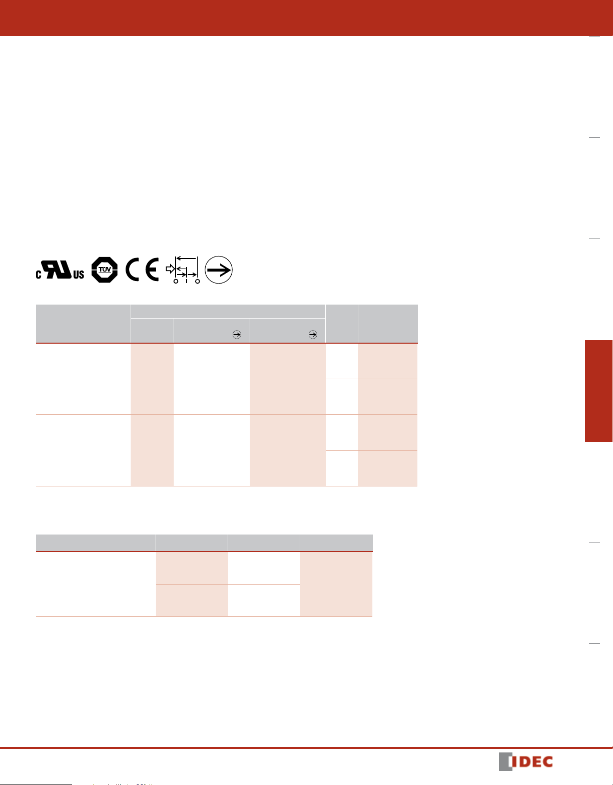
Part Numbers
Contact Conguration/No. of Contacts
Model
3-position
Switch
Button Return
Monitor Switch
Button Depress
Monitor Switch
HE6B
Overview XW Series E-Stops Interlock Switches Enabling Switches Safety Control Relays Light Curtains AS-Interface Safety at Work
Color Part Number
Accessories
Replacement Rubber Cover
Appearance Color Part Number Material
Yellow HE6B-M200Y
2 0 0
Black HE6B-M200B
Yellow HE6B-M211Y
2 1 1
Black HE6B-M211B
Yellow HE9Z-D6Y
Silicon Rubber
Black HE9Z-D6B
1607302053
405
Page 2
HE6B
Enabling Switches
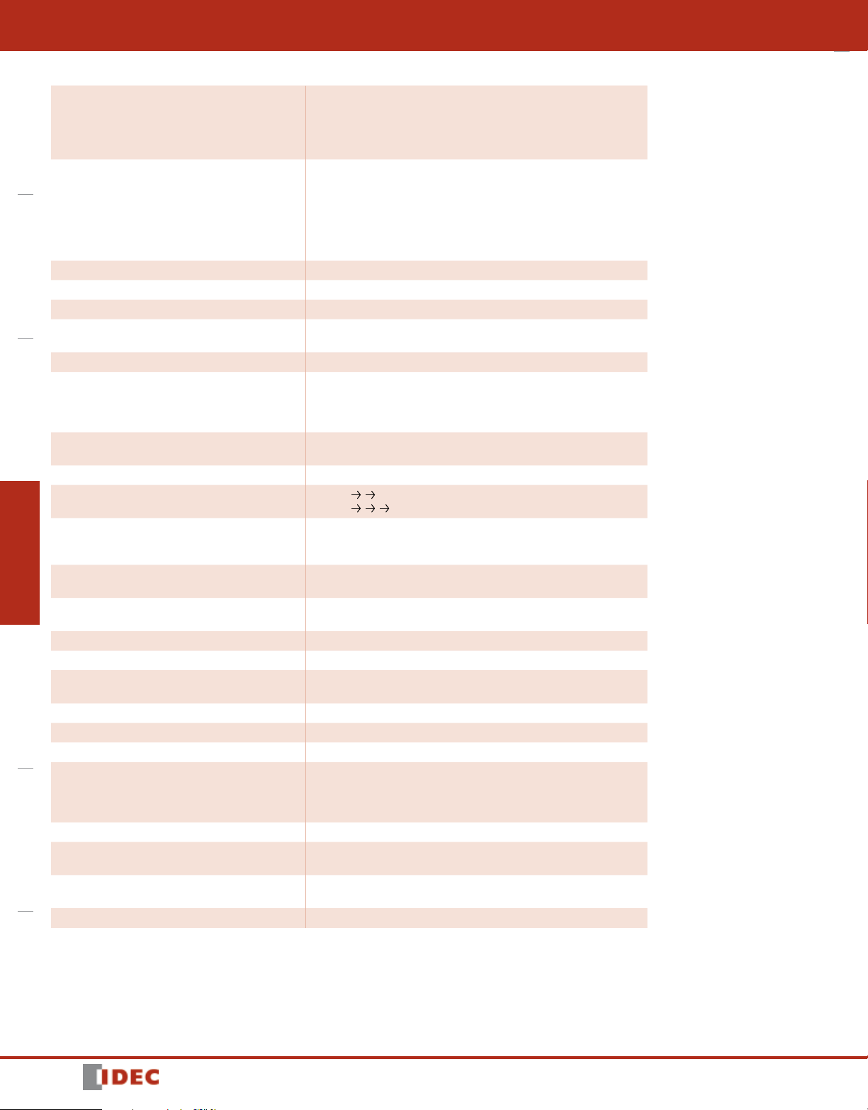
Specications
IEC 60947-5-1/EN60947-5-1
Conforming to Standards
OverviewXW Series E-StopsInterlock SwitchesEnabling SwitchesSafety Control RelaysLight CurtainsAS-Interface Safety at Work
Application Standards
for Use
Operating Temperature –25 to +60°C (no freezing)
Relative Humidity 45 to 85% RH (no condensation)
Storage Temperature –40 to +80°C (no freezing)
Pollution Degree
Contact Resistance 50mΩ maximum (initial value)
Insulation Resistance
Impulse Withstand Voltage
Operating Frequency 1200 operations per hour
Mechanical Life
Electrical Life
Shock Resistance
Vibration Resistance
Terminal Style Solder terminal
Applicable Wire Size 1 cable, 0.5mm
Solder Terminal
Heat Resistance
Terminal Tensile Strength 20N minimum
Locking Ring Recommended Tightening Torque 0.5 to 0.8N·m
Degree of Protection IP65 (IEC 60529)
Conditional Short-circuit
Current
Direct Opening Force 40N minimum (button release monitor and button depress monitor switches)
Direct Opening Stroke
(when pressing the entire button surface)
Operator Strength
Weight (approx.) 17g
IEC 60947-5-8/EN60947-5-8 (TÜV approved)
GS-ET-22 (TÜV approved)
UL508 (UL recognized)
CSA C22.2 No.14 (c-UL recognized)
ISO 12100/EN ISO 12100,
IEC 60204-1/EN 60204-1,
ISO 11161/EN ISO 11161,
ISO 10218-1/EN ISO 10218-1,
ANSI/RIA/ISO 10218-1,
ANSI/RIA/R15.06, ANSI B 11.19
ISO 13849-1/EN ISO 13849-1
2 (inside panel, terminal side)
3 (outside panel, operator side)
Between live and dead metal parts:
100MΩ minimum (500V DC megger)
Between terminals of different poles:
10 MΩ minimum (500V DC megger)
1.5kV (3 position switch)
2.5kV (monitor switch)
Position 1
Position 1 2 3 1: 100,000 operations minimum
100,000 operations minimum (rated load)
1,000,000 operations minimum
(24V AC/DC, 100 mA)
Operating extremes: 150m/s
Damage limits: 500m/s2 (50G)
Operating extremes: 5 to 55 Hz, amplitude 0.5mm
Damage limits: 16.7Hz, amplitude 1.5mm
310 to 350°C, 3 seconds maximum
50A (125V): 3-position switch
(Use 120V/10A fast acting type fuse for short circuit protection.) (IEC 60127-1)
50A (250V): monitor switch
(Use 250V/10A fast acting type fuse for short circuit protection.) (IEC 60127-1)
0.9mm minimum (button return monitor switch)
4.0mm minimum (button depress monitor switch)
250N minimum
(when pressing the entire button surface)
2 1: 1,000,000 operations minimum
2
(15G)
2
maximum (20AWG wire)
406
1607302053
Page 3

Enabling Switches
When releasing
the operator
When releasing
the operator
When pressing
the operator
21-22
(Without rubber boot
(When pressing the center
of the operator)
Position 1Position 2Position 3
6.6 19 13
16
Panel Thickness:
2-ø3.2
Mounting
Screws
Current Ratings
Rated Insulation Voltage (Ui) 125V (monitor switch: 250V)
Rated Thermal Current (Ith) 3A
Rated Voltage (Ue) 30V 125V 250V
Resistive Load (AC-12) – 0.5A –
AC
3-position switch
Button return monitor switch
Button depress
monitor switch (NC)
Rated Current (Ie)
Contact
Conguration
Minimum applicable load (reference value): 3V AC/DC, 5mA (Applicable operation area depends on the
operating conditions and load.)
Operating Characteristics
Operating Characteristics (without rubber cover/pushing button part A and B)
Inductive Load (AC-15) – 0.3A –
Resistive Load (DC-12) 1A – –
DC
Inductive Load (DC-13) 0.7A – –
Resistive Load (AC-12) – 2.5A 1.5A
AC
Inductive Load (AC-15) – 1.5A 0.75A
Resistive Load (DC-12) 2.5A 1.1A 0.55A
DC
Inductive Load (DC-13) 2.3A 0.55A 0.27A
3-position switch 2 contacts
Button return monitor switch 0 or 1 contact
Button depress monitor switch 0 or 1 contact
TÜV ratings:
3 position switch:
AC-12 125V/0.5A
DC-12 30V/1A
DC-13 30V/0.7A
Monitor Switch:
AC-15 250V/0.5A
DC-13 125V/0.22A
DC-13 30V/1A
HE6B
Overview XW Series E-Stops Interlock Switches Enabling Switches Safety Control Relays Light Curtains AS-Interface Safety at Work
UL ratings:
3-position switch:
125V AC/0.5A (Resistive)
30V DC/1A (Resistive)
Monitor switch:
250V AC/0.5A (General use)
30V DC/1A (General use)
: ON (closed)
: OFF (open)
Travel (mm)
Position
1→2→3
Position
2
→
Position
3
→
Notes: When a rubber boot is used, the operating force depends on the operating temperature.
Dimensions (mm)
4.2 6.8
Approx. 17N
(reference value)
)
Approx. 4N
NO1-C1
NO2-C2
11-12
21-22
NO1-C1
NO2-C2
11-12
1
21-22
NO1-C1
NO2-C2
11-12
1
47.7
24.6
5
5
11.3
11.3
29
03.0
10-0.5
2.5
0.9
2.3
22
15.6
3
4 4
±0.3
±0.3
±0.3
±0.5
3.6
4.0
±0.5
5.0
±0.5
Mounting Hole Layout
±0.2
16.2
6 mm maximum
Mounting screws: M3 screw × 2
(not attached and must be supplied by the user)
Mounting screw length: 5 to 6 mm (panel thickness + gasket)
29.4
37.4
±0.2
±0.2
Terminal Arrangement (bottom view)
HE6B-M211
3-position switch 2 contacts
Button return monitor switch: 1 contact, terminals 11-12
Button depress monitor switch: 1 contact, terminals 21-22
There are no terminals 11-22 and 21-22 for HE6B-M200 type.
1
Use NO and C terminals for OFF ON OFF 3-position switch
(NC terminal is not used.)
1
1607302053
407
 Loading...