

Page 1
Enabling Switches
HE2G Compact Grip Enabling Switch
Key features:
• New compact, light-weight grip switch provides a comfortable hold
• Compact design ts comfortably in the hand
• Light operating force ensures worry-free operation
• 3-position switch with distinctive tactile feedback
• Dual enabling contacts ensure a high level of safety
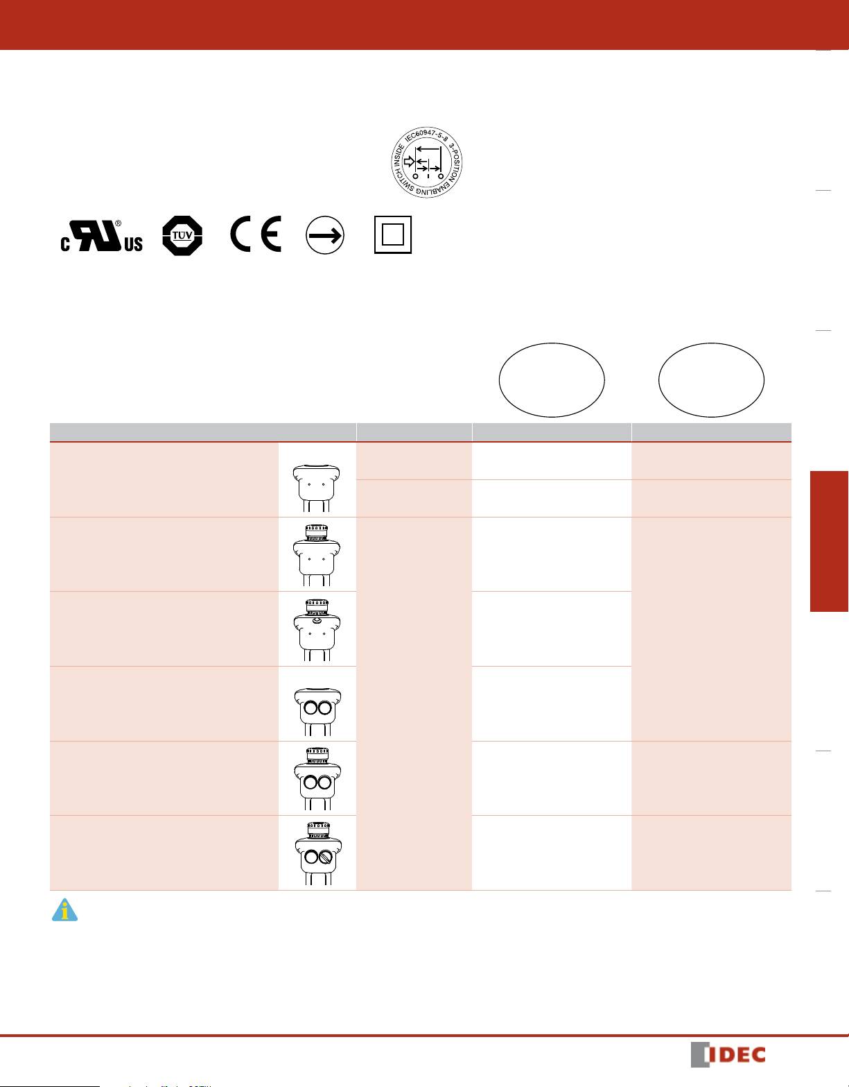
Part Numbers
Additional Control Units Rubber Boot Color Solder Terminal Internal Connector
HE2G
Overview XW Series E-Stops Interlock Switches Enabling Switches Safety Control Relays Light Curtains AS-Interface Safety at Work
None
Estop
Two Momentary Pushbuttons
E-Stop and Two Momentary Pushbuttons
E-Stop, Momentary Pushbutton and Key Switch
Yellow HE2G-21SH HE2G-21SC
Gray HE2G-21SH-1N HE2G-21SC-1N
HE2G-21SHE
HE2G-21SHE-P-0
Yellow
HE2G-21SH-L-L
HE2G-21SHE-L-L HE2G-21SCE-L-L
HE2G-21SHE-L-K HE2G-21SCE-L-K
–Estop and Green Pilot Light
1607302053
1. Additional control units installed on the HE2G are as follows:
Emergency Stop Switch: XA1E-BV3U02R
Momentary Pushbutton: AB6M-M2PLW
Key Selector Switch: AS6M-2KT2PA Pilot Light: UP9P-2498G
2. Silicon rubber: Can be used in general factories. Remains exible in cold temperatures. Suitable in applications with a
wide operating temperature range.
3. NBR/PVC polyblend: Oil-proof. Suitable for environments subjected to machine oil and painting robots where silicon
rubber cannot be used.
415
Page 2
HE2G
Enabling Switches
Specications
UL508 (UL recognition)
Applicable Standards
OverviewXW Series E-StopsInterlock SwitchesEnabling SwitchesSafety Control RelaysLight CurtainsAS-Interface Safety at Work
Applicable Standards for Use
Operating Temperature
Relative Humidity 45 to 85% (no condensation)
Storage Temperature –40 to +80°C (no freezing)
Pollution Degree 3
Contact Resistance 50 mΩ maximum (initial value)
Insulation Resistance
Impulse Withstand Voltage
Electric Shock Protection Class Class II (IEC 61140) (With pilot light: class III)
Operating Frequency 1,200 operations per hour
Mechanical Life
Electrical Life
Shock Resistance
Vibration Resistance
Applicable Wire
Applicable Wire Size
Applicable Cable Outside diameter: ø4.5 to 10 mm
Conduit Port Size M16 (cable gland is supplied)
Terminal Tensile Strength 20N minimum
Degree of Protection
Conditional Short-circuit Current 50A (250V) (Use 250V/10A fast-blow fuse for short circuit protection.)
Direct Opening Force 60N minimum (monitor switch)
Operator Strength 500N minimum (when pressing the entire button surface)
Weight (approx.)
CSA C22.2, No. 14 (c-UL recognition)
IEC/EN 60947-5-1 (TÜV)
GS-ET-22 (TÜV approval)
ISO 12100-1, -2
IEC 60204-1/EN 60204-1
ISO11161 / prEN11161
ISO 10218 / EN 775
ANSI/RIA R15.06
ANSI B11.19
Silicon rubber boot: –25 to 60°C (no freezing)
NBR/PVC Polyblend rubber boot: –10 to 60°C (no freezing)
Between live and dead metal parts: 100 MΩminimum (500V DC megger)
Between terminals of different pole: 100 MΩminimum (500V DC megger)
(Solder terminal)
Grip style enabling switch/emergency stop switch: 2.5 kV
Momentary pushbutton/key selector switch: 1.5 kV
Pilot light: 500V AC, 1 minute (between live and dead parts)
(Internal connector)
Grip style enabling switch/emergency stop switch/momentary pushbutton/key selector switch: 1.5 kV
Position 1
Position 1 2 3 1: 100,000 operations minimum
100,000 operations minimum (rated load)
1,000,000 operations minimum (24V AC/DC, 100 mA)
Operating extremes: 150 m/s
Damage limits: 1,000 m/s2 (100G)
Operating extremes: 5 to 55 Hz, amplitude 0.5 mm minimum
Damage limits: 16.7 Hz, amplitude 1.5 mm minimum
Solder terminal: 0.5 mm
Internal connector: 0.05 to 0.86 mm2 (AWG18 to 30)
Solder terminal: 0.5 mm
Internal connector: 0.05 to 0.86 mm2 (AWG18 to 30) (AWG22 between switch and connector)
With control unit: IP67/IP66 (IEC 60529)
Without control unit: IP65 (IEC 60529)
HE2G-21SH: 140g
HE2G-21SH-P-0/-21SC: 145g
HE2G-21SHE/-21SC-P-0: 150g
HE2G-21SH-L-L/-21SHE-P-0/-21SCE: 155g
HE2G-21SH-L-K/-21SCE-P-0: 160g
HE2G-21SHE-L-L/-21SC-L-L: 165g
HE2G-21SHE-L-K/-21SC-L-K: 170g
HE2G-21SCE-L-L: 175g
HE2G-21SCE-L-K: 180g
2 1: 1,000,000 operations minimum
2
(15G)
2
maximum (20 AWG)
2
(20 AWG)
416
1607302053
Page 3

Enabling Switches
Contact Ratings
Rated Insulation Voltage (Ui)
Rated Thermal Current (lth) 3A (emergency stop switch: 5A)
Rated Voltage (Ue) 30V 125V 250V
Resistive Load
(AC-12)
AC
DC
AC
DC
AC
DC
AC
DC
Inductive Load
(AC-15)
Resistive Load
(DC-12)
Inductive Load
(DC-13)
Resistive Load
(AC-12)
Inductive Load
(AC-15)
Resistive Load
(DC-12)
Inductive Load
(DC-13)
Resistive Load
(AC-12)
Inductive Load
(AC-15)
Resistive Load
(DC-12)
Inductive Load
(DC-13)
Resistive Load
(AC-12)
Inductive Load
(AC-15)
Resistive Load
(DC-12)
Inductive Load
(DC-13)
3-position switch
(Terminal No.
NO1-C1/A1-B1,
NO2-C2/A3-B3)
Monitor Switch
Grip Style Enabling Switch
(NC contact)
(Terminal No.
31-32/A2-B2)
Emergency Stop Switch
Rated Current
XA1E-BV3U02R
(Terminal No.1-2/A1-B1,
1-2/A2-B2)
Momentary Pushbutton
Key Selector Switch
Control Unit
AB6M-M2PLW,
AS6M-2KT2PA
(Terminal No.C1/B1, NO1/
B2, NC1/B3, C2/A1, NO2/
A2, NC2/A3)
UP9 Pilot Light
UP9P-2498G
(Terminal No. +, –)
250V (momentary pushbutton and key
selector: 125V) /
30V (with pilot light)
— 1A 0.5A
— 0.7A 0.5A
1A 0.2A —
0.7A 0.1A —
— 2.5A 1.5A
— 1.5A 0.75A
2.5A 1.1A 0.55A
2.3A 0.55A 0.27A
— 5A 3A
— 3A 1.5A
2A 0.4A 0.2A
1A 0.22A 0.1A
— 0.5A —
— 0.3A —
1A 0.2A —
0.7A 0.1A —
Rated operating voltage: 24V DC ±10%
Rated current: 15mA
HE2G
Overview XW Series E-Stops Interlock Switches Enabling Switches Safety Control Relays Light Curtains AS-Interface Safety at Work
1607302053
417
Page 4

HE2G
: contact OFF (open)
: contact ON (closed)
1.5 (LAPP)
Emergency Stop
Switch
)
B1
B2
NC1
NC2
OverviewXW Series E-StopsInterlock SwitchesEnabling SwitchesSafety Control RelaysLight CurtainsAS-Interface Safety at Work
Enabling Switches
Note: Minimum applicable load (reference value): 3V AC/DC, 5 mA
(Applicable range is subject to the operating conditions and load.)
*Operating temperature for internal connectors:
–25°C min., 40°C max. 2.5A (12 to 19 poles), 2A (20 to 22 poles)
40°C min., 50°C max. 2.5A (8 to12 poles), 2A (13 to 22 poles)
50°C min., 60°C max. 2.5A (6, 7 poles), 2A (8 to13 poles), 1.5A (14 to 22 poles)
Operation Characteristics
Terminal No.
Internal Connector/
Solder Terminal
Pressing
(Position 1➞2➞3)
⇨
Releasing
(Position 2➞1)
⇦
Releasing
(Position 3➞1)
⇦
NO1—C1/A1-B1
31—32/A2-B2
NO2—C2/A3-B3
NO1—C1/A1-B1
31—32/A2-B2
NO2—C2/A3-B3
NO1—C1/A1-B1
31—32/A2-B2
NO2—C2/A3-B3
Terminals NO1-C1/A1-B1, NO2-C2/A3-B3 are outputs of the 3-position
enabling switch.
The above operation characteristics show when the center of the grip
switch button is pressed. Because two contacts are designed to operate
independently, pressing the edge of the button turns on one contact
earlier than the other contact, causing a delay in operation To avoid this,
always press the center of the button.
Position 1Position 2Position 3
Dimensions (mm)
HE2G-21SH/HE2G-21SC
83
62
50
134
(64)
(94)
Cable Gland (supplied with grip switch)
Type No.: SKINTOP BS-M16
Internal Connector
Cable side connector:
Tyco Electronics D-1200D Series
1827586-2: AWG28 to 30
(Hand tool: 1762952-1)
1827587-2: AWG22 to 28
(Hand tool: 1762846-1)
1827588-2: AWG22 to 28
(Hand tool: 1762950-1)
1827589-2: AWG18 to 22
(Hand tool: 1762625-1)
Specify 2 or 3 in place of .
2: 4-pin connector
3: 6-pin connector
The customer needs to purchase the connector
×
separately.
All dimensions in mm.
Additional Control Unit Layout Contact Arrangement (Internal Connector)
Internal Connector Pin No.
4-pin
B2B1
A2A1
6-pin
3-position switch /control unit side connector:
Tyco Electronics D-1200D Series
B3B2B1
A3A2A1
Tab housing: 1-1903130-2 (4-pin connector)
1-1903130-3 (6-pin connector)
Tab contact: 19303116-2
Control Unit (A)
Control Unit (B)
Emergency Stop
Switch
Pilot Light (C
• Receptacle: 1-1827864-
• Receptacle contact
Emergency stop
switch
Terminal Arrangement (TOP VIEW) 6-Pin Connector Allotment Table
A1
A2
Emergency stop switch
NO2
NO1
C2
C1
Momentary pushbutton
Key selector switch
Internal Connector
Momentary pushbutton
Pin No.
A1 C2
A2 NO2
A3 NC2
B1 C1
B2 NO1
B3 NC1
Key selector switch
3-position switch
Momentary pushbutton
Key selector switch
418
1607302053
 Loading...