

HE2B
HE2B Redundant (Double) Basic Enabling Switch
Key features:
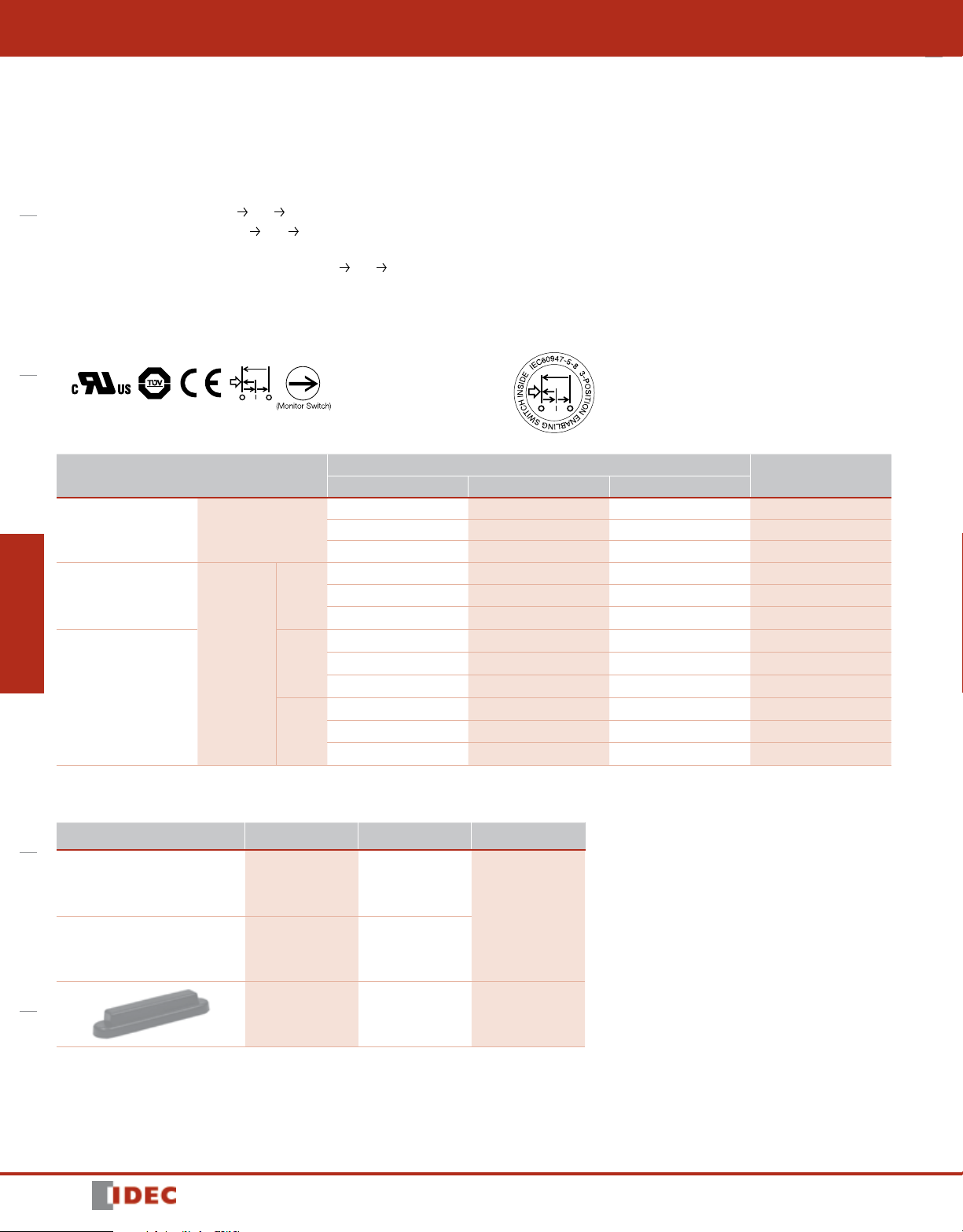
• 3-position functionality (OFF – ON –OFF) as required for manual robotic control
OverviewXW Series E-StopsInterlock SwitchesEnabling SwitchesSafety Control RelaysLight CurtainsAS-Interface Safety at Work
• Ideally suited for use as enabling (aka “deadman”) switch on teach pendants
• Provides a high level of safety based on human behavioral studies that determine
personnel may squeeze OR let go when presented with a panic situation
• Snap acting contacts from Off On (1 2)
• Positive action contacts from On Off (2 3) ensure no contact welding (per
EN60947-5-1 / IEC60947-5-1)
• Contacts will not re-close when released from Off On (3 1) (per IEC60204-1;
9.2.5.8)
• Multiple contacts for enhanced reliability
• Monitoring contacts in addition to main load contacts
• Available with or without rubber cover (cover provides IP65 watertight seal)
Part Numbers
Style
Without Rubber Cover
With Rubber
Cover
Yellow
Black
Gray
3 Position Switch Push Monitor Switch Return Monitor Switch
2 0 0 HE2B-M200
2 1 1 HE2B-M211
2 2 2 HE2B-M222
2 0 0 HE2B-M200PY
2 1 1 HE2B-M211PY
2 2 2 HE2B-M222PY
2 0 0 HE2B-M200PB
2 1 1 HE2B-M211PB
2 2 2 HE2B-M222PB
2 0 0 HE2B-M200PN1
2 1 1 HE2B-M211PN1
2 2 2 HE2B-M222PN1
Enabling Switches
Number of Contacts
Part Number
Accessories
Replacement Rubber Cover
Apperance Color Part Number Material
396
Yellow HE9Z-D2Y
Silicon Rubber
Black HE9Z-D2B
Gray HE9Z-D2N1 NBR/PVC Polyblend
1607302053
Enabling Switches
Specications
Conforming to Standards
Application Standards
Operating Temperature –25 to +60˚C (no freezing)
Operating Humidity 45 to 85% RH (no condensation)
Storage Temperature –40 to +80˚C (no freezing)
Pollution Degree
Contact Resistance 50mΩ maximum
Insulation Resistance
Impulse Withstand Voltage 2.5kV
Operating Frequency 1200 operations/hour
Mechanical Life
Electrical Life 100,000 (at full rated load)
Shock
Resistance
Vibration
Resistance
Terminal 0.110” quick connect / solder terminal
Recommended Wire Size 0.5mm2 maximum / 1 line (20AWG)
Solder Heat Resistance 310 ~ 350°C / 3 seconds maximum
Terminal Pulling Strength 20N minimum
Recommended Screw Torque 0.5 to 0.8Nm
Degree of Protection
Conditional Short-Circuit Current 50A (250V)
Recommended Short Circuit Protection 250V/10A fast blow fuse (IEC 60127-1)
Circuit Opening Force 60N minimum (button return monitor & button push monitor)
Actuating Force (Operating) 500N minimum
Weight Approx. 26g (without cover), 30g (with cover)
Operating Extremes 150m/s2 (15 G)
Damage Limits 1000m/s2 (100 G)
Operating Extremes 5 to 55Hz, amplitude 0.5mm minimum
Damage Limits 16.7Hz, amplitude 1.5mm minimum
UL508 (UL recognized), CSA C22.2, No. 14 (c-UL recognized),
IEC/EN 60947-5-1, IEC/EN 60947-5-8 (TÜV approval)
ISO 12100-1, -2, EN 12100-1, 2 / EN 292, IEC 60204-1 / EN 60204-1
ISO11161 / prEN 11161, ISO10218 / EN 775, ANSI / RIA R15.06, ANSI B11.19
2 (inside of panel/contact side)
3 (outside of panel/operating side)
Between live and dead metal parts: 100MΩ maximum
Between positive and negative live parts: 100MΩ minimum
Position 1 2: 1,000,000 operations minimum
Position 1
with rubber cover: IP65,
without rubber cover: IP40 (IEC 60529),
2 3 1: 100,000 operations minimum
HE2B
Overview XW Series E-Stops Interlock Switches Enabling Switches Safety Control Relays Light Curtains AS-Interface Safety at Work
Contact Ratings
1607302053
Rated Insulation Voltage (Ui) 250V
Thermal Current (lth) 3A
Rated Operating Voltage (Ue) 30V 125V 250V
Resistive Load (AC-12) – 1A 0.5A
AC
3 Position
Switch
Rated Operating
Current (le)
Push/return
Monitor Switch
(NC Contacts)
Contact Conguration
Minimum applicable load (reference) = AC/DC3V • 5mA (for reference only)
Return Monitor Switch 0 ~ 2 contacts (NC)
Push Monitor Switch 0 ~ 2 contacts (NC)
Inductive Load (AC-15) – 0.7A 0.5A
Resistive Load (DC-12) 1A 0.2A –
DC
Inductive Load (DC-13) 0.7A 0.1A –
Resistive Load (AC-12) – 2.5A 1.5A
AC
Inductive Load (AC-15) – 1.5A 0.75A
Resistive Load (DC-12) 2.5A 1.1A 0.55A
DC
Inductive Load (DC-13) 2.3A 0.55A 0.27A
3 Position Switch 2 contacts (DPDT)
397

HE2B
Label Side
Label Side
Label Side
41-42
Position 1 Position 2 Position 3
M3 nut hole
16
19
Mounting Panel Thickness: 6 max.
Circuit Diagrams
Terminal Circuit Diagrams (bottom view)
Enabling Switches
OverviewXW Series E-StopsInterlock SwitchesEnabling SwitchesSafety Control RelaysLight CurtainsAS-Interface Safety at Work
HE2B-M200
Operating Characteristics
Operating Characteristics (without rubber cover/center of button being pushed)
Approx. 30N
Operating Force (reference value)
(without rubber boot, when pressing
the center)
: ON (closed)
: OFF (open)
(position 1 to 2 to 3)
Pressing
Releasing
(position 2 to 1)
Releasing
(position 3 to 1)
Approx. 4N
Travel (mm)
NO1-C1
NO2-C2
11-12
21-22
31-32
41-42
NO1-C1
NO2-C2
11-12
21-22
31-32
41-42
NO1-C1
NO2-C2
11-12
21-22
31-32
0
1.4
HE2B-M211
±0.3
2.4
±0.3
3.0
±0.3
3.6
±0.5
4.2
±0.5
6.0
HE2B-M222
±0.5
Using rubber boot will change the operating force depending on the operating temperature.
Dimensions (mm)
Without Rubber Cover With Rubber Cover Mounting Hole Layout
10
66.5
87
78
5.5
13.5
14.2
5
69
7
11.5
90
68
69
6.5
14.8
14.2
5
7
+0.2
0
12.2
Mounting Screws
2-ø3.2
±0.2
70
±0.2
78
398
1607302053
 Loading...