

Page 1
HE1G Series Safety Products
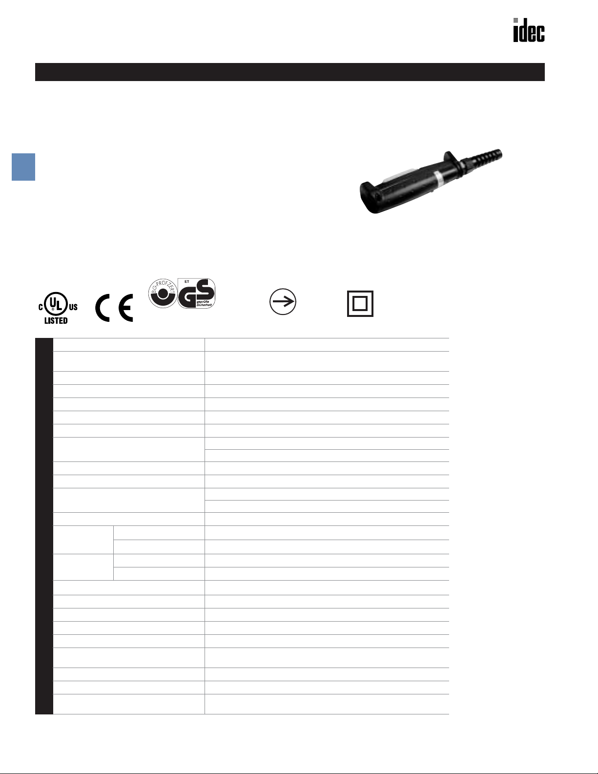
HE1G Series Grip Style Enabling Switch
HE1G
Key features include:
• 3 position funtionality (Off – On – Off) as required for manual robotic control
• Ideally suited for use as enabling (aka "deadman") switch for second operator in robotic cells
• Provides a high level of safety based on human behavioral studies that
determine personnel may squeeze OR let go when presented with a panic
B
situation
• Contacts will not re-close when released from Off
➔On (3➔1) (per IEC60204-
1; 9.2.5.8)
• Optional E-Stop switch built in
• Connection for conduit and cable strain relief built in
• IP66 waterproof sealing
• Meets ANSI robotics standards
• Optional mounting button built-in
Safety Products
GS-ET-15
BG standard in Germany
Conforming to Standards
Approvals
Operating Temperature
Operating Humidity
Storage Temperature
Pollution Degree
Contact Resistance
Insulation Resistance
Impulse Withstand Voltage
Operating Frequency
Mechanical Life
Electrical Life
Shock Resistance
Specifications
Vibration
Resistance
Operating Extremes
Damage Limits
Operating Extremes
Damage Limits
Recommend Wire Size
Recommend Cable Size
Conduit Size
Terminal Pulling Strength
Terminal Screw Torque
Degree of Protection
Conditional Short Circuit Current
Recommended Short Circuit Protection
Weight
Direct Opening Action
IEC60947-5-1, EN60947-5-1, JIS C8201-5-1, UL508, CSA C22.2 No 14
ISO12100/EN292, IEC60204-1/EN60204-1, ISO11161/prEN11161, ISO10218/
EN775, ANSI/RIA R15.06
–25 to +60˚C (no freezing)
45 to 85% RH maximum (no condensation)
–40 to +80˚C (no freezing)
3
100mΩ maximum (beginning stage)
Between live & dead metal parts: 100MΩ maximum (at 500VDC mega)
Between positive & negative live parts: 100MΩ minimum (at 500VDC mega)
2.5kV
1200 operations/hour
Position 1➔2 1 million minimum
Position 1➔2➔3➔1: 100,000 minimum
100,000 minimum at rated load
2
100m/s
2
1000m/s
5 to 55Hz, amplitude 0.5mm minimum
16.7Hz, amplitude 1.5mm minimum
0.14 to 1.5mm
ø7 to 13mm
M20
20N minimum
0.5 to 0.6N • m
HE1G-21SM: IP66, HE1G-20MB: IP65
HE1G-20ME: IP65, HE1G-21SMB: IP65
50A (250V)
250V/10A fast blow fuse (IEC 60127-1)
Approx. 250g (HE1G-20ME)
Approx. 210g (HE1G-21SM)
2
Double Insulation
B-48 www.idec.com USA: (800) 262-IDEC or (408) 747-0550, Canada (888) 317-IDEC
Page 2
Safety Products HE1G Series
Part Numbers
Part Numbers
Part Numbers 3 Position Switch Monitor Switch Emergency Stop Pushbutton Momentary Pushbutton
HE1G-21SM 2 Contacts Yes (1NC) No No
HE1G-20ME 2 Contacts No Yes (2NC) No
HE1G-21SMB 2 Contacts Yes (1NC) No Yes (1NO)
HE1G-20MB 2 Contacts No No Yes (2NO)
Ratings
Contact Ratings
Rated Insulation Volute (Ui)
Thermal Current (lth)
Rated Operating Voltage (Ue)
3 Position Switch
(Terminal No.1-2, 3-4)
Monitor Switch
(Terminal No. 5-6 of
HE1G-21SM)
Emergency Stop Pushbutton
Rated Operating Current (le)
(Terminal No. 5-6, 7-8 of
HE1G-20ME)
3 Position Switch 2 Contacts
Contact Structure
Monitor Switch 0 or 1 Contact
Emergency Stop Pushbutton 0 or 2 Contacts
Momentary Pushbutton 0 to 2 Contacts
Resistive Load (AC-12) – 3A 0.5A
AC
Inductive Load (AC-15) – 1.5A 0.5A
Resistive Load (DC-12) 2A 0.4A –
DC
Inductive Load (DC-13) 1A 0.22A –
Resistive Load (AC-12) – 2A 1A
AC
Inductive Load (AC-15) – 1A 0.5A
Resistive Load (DC-12) 2A 0.4A 0.2A
DC
Inductive Load (DC-13) 1A 0.22A 0.1A
Resistive Load (AC-12) – – –
AC
Inductive Load (AC-15) – – 0.5A
Resistive Load (DC-12) – – –
DC
Inductive Load (DC-13) – – 0.1A
250V
3A
30V 125V 250V
B
Safety Products
The minimum load (reference) = AC/DC3V • 5mA
(for reference only, varies depending on operating conditions)
www.idec.com USA: (800) 262-IDEC or (408) 747-0550, Canada (888) 317-IDEC B-49
Page 3

HE1G Series Safety Products
)
5
)
Ty
)
)
58
46
54
)
Ty
)
)
46
)
Ty
)
A
l
h
Operation Characteristics
Contact Movement
HE1G-21SM/HE1G-21SMB
●HE1G-21SM
B
When
Pushing
Button
When Button
is Released
Position 1 Position 2 Position 3
Terminal
No.
1–2
5–6
3–4
1–2
5–6
3–4
HE1G-20ME/HE1G-20MB
●HE1G-20ME
When Pushing
Button
When Button
is Released
Safety Products
Momentary
Pushbutton
Emergency
Stop
Pushbutton
Position 1 Position 2 Position 3
Terminal
No.
1–2
3–4
1–2
3–4
5–6
7–8
Contact
Contact
1. Terminals No. 1-2, 3-4, 5-6 will become positive
action when moving from position 2 to 3.
: Contact ON (Close) : Contact OFF (Open)
2. Use terminal contacts 1-2 and 3-4 for safest circuit.
Dimensions
HE1G-21SM HE1G-20ME HE1G-20MB/21SMB
dditiona
Pushbutton Switc
86
Connector (supplied with grip switch
pe No. SKINTOP BS-M20×1.5 (LAPP
86
Connector (supplied with grip switch
pe No. SKINTOP BS-M20×1.5 (LAPP
86
Connector (supplied with grip switch
pe No. SKINTOP BS-M20×1.5 (LAPP
Accessories
Part Numbers: Replacement Rubber Cover Part Numbers: Mounting Plate (secures grip switch)
Appearance Part Number Material Color Appearance Part Number Material
M4 hole
M5 Hole
(2 - ø5.3
Material: SUS304
Thickness: t=3.0mm
HE9Z-GBK1
Silicon
Rubber
Yellow HE9Z-GH1 Metal
B-50 www.idec.com USA: (800) 262-IDEC or (408) 747-0550, Canada (888) 317-IDEC
Page 4
Safety Products General Information
The above values apply when using IDEC strain r elief .
If using other, contact manufacturer.
General Information for Enabling Switches
Safety Precautions
• In order to avoid electric shock or fire, turn power off before installation, removal, wire connection, maintenance or inspection of
switch.
• Follow specification when installing. Improper electrical load may
damage switch, cause electric shock, or fire.
Installation Precautions
HE2B
• M3 nut is inside the rubber cover.
Panel
Thickness (6mm)
Mounting Screw
HE2B/HE3B
• A change in internal air pressure may cause the rubber boot to
expand and shrink on an enabling switch that has the rubber boot
sealed. This may affect the performance of the switch. Periodically
check to ensure that the enabling switch is operating correctly.
Wiring Precautions
• Use proper wire diameter to meet voltage and current requirements.
Using improper wires or incomplete soldering may cause fire due to
abnormal heat generation.
B
Safety Products
• If the panel is not level when mounting an enabling switch, the
waterproof feature cannot be guaranteed.
HE3B
• The rubber boot has a tab to be used for orientation. When making a
positioning hole in a panel, do not make a hole in the rubber boot, or
the waterproof feature cannot be guaranteed. When the positioning
hole in not on the panel, remove the tab, but do not make a hole in
the rubber boot.
• When tightening the locking ring, secure the flange to prevent the
enabling switch from rotating. In applications where the enabling
switch is to be rotated, mount the switch in a recess on the panel as
shown.
HE1B/HE2B/HE3B
• Applicable wire size is 0.5mm (maximum) / 1 line.
• When soldering the terminal, solder at a temperature of 260°C within
3 seconds. Use non-corrosive liquid rosin as soldering flux.
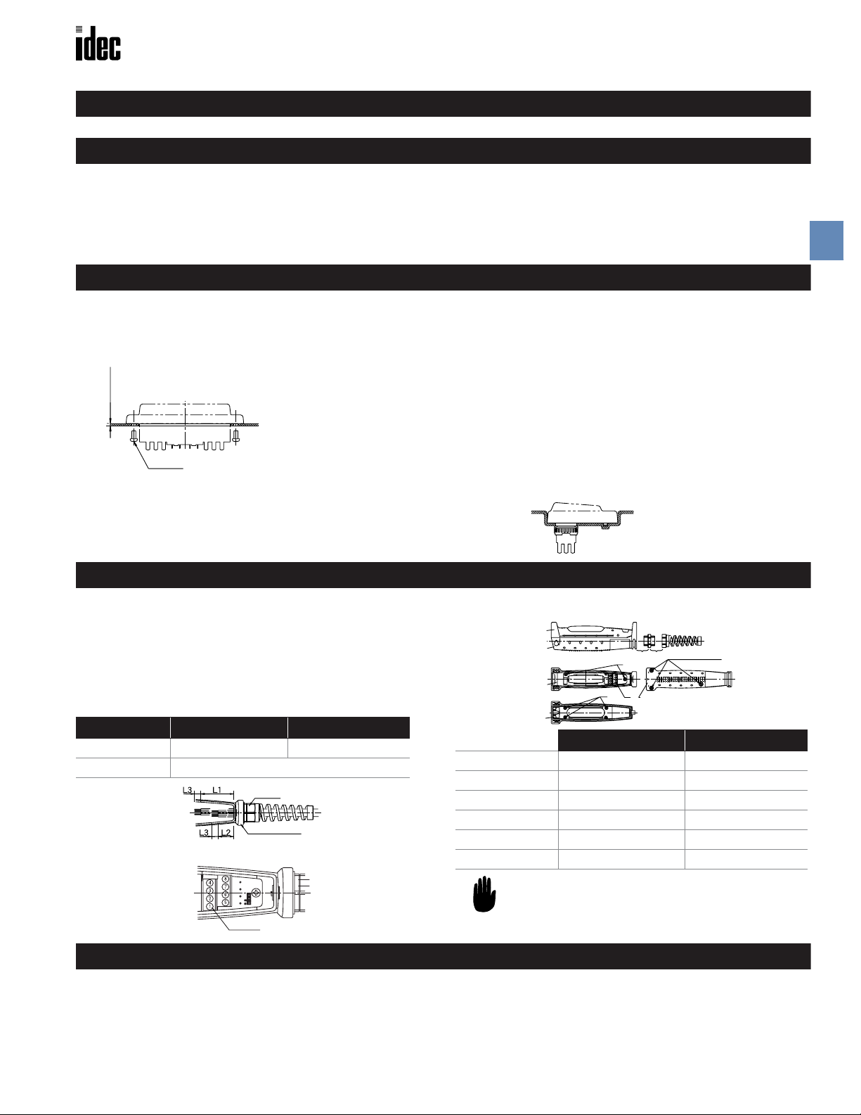
HE1G
• Wire Striping Information
Wire Length Terminal No. 1-4 Terminal No. 5-8
L1, L2 (mm) L1=40mm L2=27mm
L3 (mm) L3=6mm
Nut
Grip Switch
• Applicable Wire Size:0.14 to 1.5mm2 (one wire per terminal)
Terminal No.
Use Precautions
HE2B/HE3B/HE1G
• To ensure the highest level of reliability connect both contacts to a
monitoring device such as a safety relay.
• Recommended Torque (wire diameter range.276 - .512”)
cover
base
base
cover
F
B
E
C D
base
A (M4 screw x 3)
See Drawing Above Recommended Torque
Case Installation A 1.2±0.1N • m
Rubber Installation B .09±0.1N • m
Connector C 3.0±0.3N • m
Strain Relief D 6.0±0.3N • m
Wire terminals E 0.3±0.2N • m
Do Not Remove F –
HE1B/HE2B/HE3B
• When installing the enabling switch ensure that it cannot be accidently activated. For example, a protrusion from a teaching pendant
could cause the enabling switch to be activated by the weight of the
teaching pendant.
www.idec.com USA: (800) 262-IDEC or (408) 747-0550, Canada (888) 317-IDEC B-51
Page 5
Emergency Stop Pushbuttons Safety Products
D
IDEC Oiltight Emergency Stop Pushbuttons
Pushlock Turn Resets
L6 Series
(see page A38 for more information)
B
HA1B ø25 mm
• ø25 mm red button
• Mounting hole: ø16.2 mm
• Solder or PC board terminal
• 1NC or 2NC contacts
D
• Contact rating: 250V AC/1.5A
• Positive action contacts
• Degree of protection: IP65
Safety Products
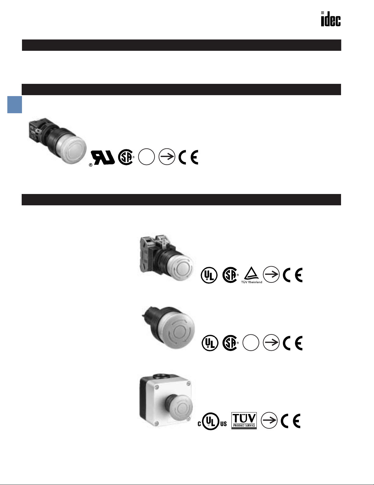
HW Series
(see page A75 for more information)
HW1B ø 29 mm
• ø29 mm red button
• Mounting hole: ø22.3 mm
• 1NO-1NC,1NC, 1NO-1NC, or 2NC contacts
• Contact rating: 220V AC/3A
• EN418 compliance
• Degree of protection: IP65
HW1E ø 40 mm Unibody
• ø40 mm red button
• Mounting hole ø22.3 mm
• 1NO-1NC, 1NC, 1NO-1NC, or 2NC contacts
• Contact rating: 220V AC/3A
• EN418 compliance
• Degree of protection: IP65
HW1X E-stop Station
• ø40 mm red button
• 1NO-1NC, 1NC, 1NO-1NC, or 2NC contacts
• Contact rating: 220V AC/3A
• Box color: Yellow (top), Black (bottom)
• EN418 compliance
• Degree of protection: IP65
B-52 www.idec.com USA: (800) 262-IDEC or (408) 747-0550, Canada (888) 317-IDEC
 Loading...