


FC6A SERIES
All-in-One Type
Communication Manual
B-1730(3)
SAFETY PRECAUTIONS
Warning
Caution
• Read the "FC6A Series MicroSmart All-in-One Type Communication Manual" to ensure correct operation before starting installation, wiring,
operation, maintenance, and inspection of the FC6A Series MicroSmart.
• All FC6A Series MicroSmart modules are manufactured under IDEC’s rigorous quality control system, but users must add a backup or failsafe
provision to the control system when using the FC6A Series MicroSmart in applications where heavy damage or personal injury may be caused,
in case the FC6A Series MicroSmart should fail.
• In this manual, safety precautions are categorized in order of importance:
Warning notices are used to emphasize that improper operation may cause severe personal injury or death.
• The FC6A Series MicroSmart is not designed for use in applications requiring a high degree of reliability and safety. The FC6A Series MicroSmart
should not be used for such applications.
• When using the FC6A Series MicroSmart in applications (not described above) that require a high degree of reliability in terms of functionality
and precision, appropriate measures such as failsafe mechanisms and redundant mechanisms must be taken for the system containing the
FC6A Series MicroSmart. The following are specific examples.
• Emergency stop and interlocking circuits must be configured outside the FC6A Series MicroSmart.
• If relays or transistors in the FC6A Series MicroSmart output circuits should fail, outputs may remain at on or off state. For output signals
which may cause serious accidents, configure monitor circuits outside the FC6A Series MicroSmart.
• The FC6A Series MicroSmart self-diagnostic function may detect internal circuit or program errors, stop programs, and turn outputs off.
Configure circuits so that the system containing the FC6A Series MicroSmart is not jeopardized when outputs turn off.
• Turn off power to the FC6A Series MicroSmart before installation, removal, wiring, maintenance, and inspection of the FC6A Series MicroSmart.
Failure to turn power off may cause electrical shocks or fire hazard.
• Special expertise is required to install, wire, program, and operate the FC6A Series MicroSmart. People without such expertise must not use the
FC6A Series MicroSmart.
• Install the FC6A Series MicroSmart according to the instructions described in the "FC6A Series MicroSmart All-in-One Type User’s Manual".
Improper installation will result in falling, failure, or malfunction of the FC6A Series MicroSmart.
Caution notices are used where inattention might cause personal injury or damage to equipment.
• The FC6A Series MicroSmart is designed for installation in a cabinet. Do not install the FC6A Series MicroSmart outside a cabinet.
• Install the FC6A Series MicroSmart in e nvironments described in the "FC6A Series MicroSmart All-in-One Type Us er’s Manual". If the FC6A Series
MicroSmart is used in places where the FC6A Series MicroSmart is subjected to high-temperature, high-humidity, condensation, corrosive gases,
excessive vibrations, or excessive shocks, then electrical shocks, fire hazard, or malfunction will result.
• The environment for using the FC6A Series MicroSmart is "Pollution degree 2." Use the FC6A Series MicroSmart in environments of pollution
degree 2 (according to IEC 60664-1).
• Prevent the FC6A Series MicroSmart from falling while moving or transporting the FC6A Series MicroSmart, otherwise damage or malfunction of
the FC6A Series MicroSmart will result.
• Wiring must use lead sizes that are appropriate for the applied voltage and current. Terminal screws must be tightened with the prescribed
tightening torque.
• Prevent metal fragments and pieces of wire from dropping inside the FC6A Series MicroSmart housing. Put a cover on the FC6A Series
MicroSmart modules during installation and wiring. Ingress of such fragments and chips may cause fire hazard, damage, or malfunction.
• Use a power supply of the rated value. Use of a wrong power supply may cause fire hazard.
• Use an IEC 60127-approved fuse on the power line outside the FC6A Series MicroSmart. This is required when equipment containing the FC6A
Series MicroSmart is destined for Europe.
• Use an IEC 60127-approved fuse on the output circuit. This is required when equipment containing the FC6A Series MicroSmart is destined for
Europe.
• Use an EU-approved circuit breaker. This is required when equipment containing the FC6A Series MicroSmart is destined for Europe.
• Make sure of safety before starting and stopping the FC6A Series MicroSmart or when operating the FC6A Series MicroSmart to force outputs on
or off. Incorrect operation of the FC6A Series MicroSmart may cause machine damage or accidents.
• Do not connect the ground wire directly to the FC6A Series MicroSmart. Connect a protective ground to the cabinet containing the FC6A Series
MicroSmart using an M4 or larger screw. This is required when equipment containing the FC6A Series MicroSmart is destined for Europe.
• Do not disassemble, repair, or modify the FC6A Series MicroSmart modules.
• The FC6A Series MicroSmart contains electronic parts and batteries. When disposing of the FC6A Series
MicroSmart, do so in accordance with national and local regulations.
Preface-1 FC6A S
ERIES MICROSMART ALL-IN-ONE TYPE COMMUNICATION MANUAL
FC9Y-B1730

ABOUT THIS MANUAL
This manual describes functions, specifications, installation, and operation basics of the FC6A Series MicroSmart. Also included is
information on the powerful communications tools of the FC6A Series MicroSmart, as well as troubleshooting procedures.
Chapter 1: General Information
General information about the FC6A Series MicroSmart with communication interfaces.
Chapter 2: Devices
Descriptions of the allocations of devices such as inputs, outputs, internal relays, registers, timers, and counters that are used in
the basic and advanced instructions, as well as details about the allocations of special internal relays and special data registers for
communication functions.
Chapter 3: Communication Settings
Functions for the FC6A Series MicroSmart communication, how to configure them, and examples of their use.
Chapter 4 through Chapter 8:
Various communication functions such as maintenance communication, user communication, Modbus communication, data link
communication and J1939 communication.
Chapter 9: PING Instruction
Descriptions of the PING instruction that sends a ping packet to the specified remote host to check if communication is possible at
the Internet Protocol (IP) layer.
Chanpter 10: Send E-mail Function
Descriptions of the EMAIL instruction that sends preregistered e-mails.
Chanpter 11: Web Server
Description of the Web server functions in the FC6A Series MicroSmart.
Index
Alphabetical listing of key words.
Publication history
December 2015 First Edition
February 2016 Second Edition
April 2016 Third Edition
March 2017 Fourth Edition
Trademarks
FC6A Series MicroSmart is a trademark of IDEC Corporation.
FC6A S
ERIES MICROSMART ALL-IN-ONE TYPE COMMUNICATION MANUAL
FC9Y-B1730 Preface-2

Regarding laws and compatible standards
IMPORTANT INFORMATION
Under no circumstances shall IDEC Corporation be held liable or responsible for indirect or consequential damages resulting from
the use of or the application of IDEC PLC components, individually or in combination with other equipment.
All persons using these components must be willing to accept responsibility for choosing the correct component to suit their
application and for choosing an application appropriate for the component, individually or in combination with other equipment.
All diagrams and examples in this manual are for illustrative purposes only. In no way does including these diagrams and
examples in this manual constitute a guarantee as to their suitability for any specific application. To test and approve all
programs, prior to installation, is the responsibility of the end user.
This product adheres to the laws and compatible standards of all countries involved, as shown below.
European laws and standards
This product complies with the following EU directives.
• Low Voltage Directive
• EMC Directive
To comply with these directives, this product has been designed and evaluated on the basis of the following international and
European standard.
• IEC/EN 61131-2: 2007
For details on the compatible standards and EU Directives, contact the distributor from which you purchased this product or visit our web site.
North America laws and standards
This product complies with the following standards.
• UL508
• CSA C22.2 No.142
• ANSI/ISA 12,12,01
• CAN/CSA C22.2 No.213
*1 Certain FC6A Series MicroSmart models are not compatible. For details, please contact IDEC Corporation.
For details on compatible standards and EU directives, please contact the dealer where purchased or check the IDEC website.
*1
*1
Preface-3 FC6A S
ERIES MICROSMART ALL-IN-ONE TYPE COMMUNICATION MANUAL
FC9Y-B1730

RELATED MANUALS
The following manuals related to the FC6A Series MicroSmart are available. Refer to them in conjunction with this manual.
Type No. Manual Name Description
Describes product specifications, installation and wiring instructions, instructions for
FC9Y-B1722
FC9Y-B1726
FC9Y-B1730
FC9Y-B1734
WindLDR Help
FC6A Series MicroSmart
All-in-One Type User’s Manual
FC6A Series MicroSmart
LAD Programming Manual
FC6A Series MicroSmart
All-in-One Type Communication
Manual (this manual)
FC6A Series MicroSmart
PID Module User's Manual
basic programming operations and special functions, device and instruction lists,
communication functions, and troubleshooting procedures for the FC6A Series
MicroSmart series.
Describes basic operations for programming with ladders on the FC6A Series
MicroSmart, monitoring methods, device and instruction lists, and details of each
instruction.
Describes specifications related to FC6A Series MicroSmart communication,
descriptions of functions, configuration methods, and usage examples.
Describes PID module specifications and functions.
Describes usage instructions for WindLDR, programming software for the FC6A
Series MicroSmart series.
FC6A S
ERIES MICROSMART ALL-IN-ONE TYPE COMMUNICATION MANUAL
FC9Y-B1730 Preface-4
NAMES AND ABBREVIATIONS USED IN THIS MANUAL
Model Names
Name Used in This Manual Type Number, Part Code, or Official Name
FC6A Series MicroSmart FC6A Series MICROSmart
FC6A-C16R1AE, FC6A-C16R1CE, FC6A-C16K1CE, FC6A-C16P1CE,
All-in-One Type
CAN J1939 All-in-One Type
16-I/O type
24-I/O type
40-I/O type
CPU module
AC power type FC6A-C16R1AE, FC6A-C24R1AE, FC6A-C40R1AE, FC6A-C40R1AEJ
24V DC power type
DC power type
12V DC power type
Relay output type
Transistor sink output
Transistor output type
Expansion module Expansion I/O module, functional module
Expansion I/O module Input module, output module, mixed I/O module
Functional module Analog module, PID module
Analog module
Option module
Cartridge Analog cartridge, communication cartridge
WindLDR WindLDR application software
USB cable
type
Transistor protection
source output type
FC6A-C24R1AE, FC6A-C24R1CE, FC6A-C24K1CE, FC6A-C24P1CE,
FC6A-C40R1AE, FC6A-C40R1CE, FC6A-C40K1CE, FC6A-C40P1CE,
FC6A-C40R1DE, FC6A-C40R1DE, FC6A-C40K1DE, FC6A-C40P1DE
FC6A-C40R1AEJ, FC6A-C40R1CEJ, FC6A-C40K1CEJ, FC6A-C40P1CEJ,
FC6A-C40R1DEJ, FC6A-C40K1DEJ, FC6A-C40P1DEJ
The general term for the model with 16 I/O points
(FC6A-C16R1AE, FC6A-C16R1CE, FC6A-C16K1CE, FC6A-C16P1CE)
The general term for the model with 24 I/O points
(FC6A-C24R1AE, FC6A-C24R1CE, FC6A-C24K1CE, FC6A-C24P1CE)
The general term for the model with 40 I/O points
(FC6A-C40R1AE, FC6A-C40R1CE, FC6A-C40K1CE, FC6A-C40P1CE,
FC6A-C40R1DE, FC6A-C40R1DE, FC6A-C40K1DE, FC6A-C40P1DE,
FC6A-C40R1AEJ, FC6A-C40R1CEJ, FC6A-C40K1CEJ, FC6A-C40P1CEJ,
FC6A-C40R1DEJ, FC6A-C40K1DEJ, FC6A-C40P1DEJ)
FC6A-C16R1CE, FC6A-C24R1CE, FC6A-C40R1CE, FC6A-C16K1CE,
FC6A-C24K1CE, FC6A-C40K1CE, FC6A-C16P1CE, FC6A-C24P1CE,
FC6A-C40P1CE, FC6A-C40R1CEJ, FC6A-C40K1CEJ, FC6A-C40P1CEJ
FC6A-C40R1DE, FC6A-C40K1DE, FC6A-C40P1DE, FC6A-C40R1DEJ,
FC6A-C40K1DEJ, FC6A-C40P1DEJ
FC6A-C16R1AE, FC6A-C16R1CE, FC6A-C24R1AE, FC6A-C24R1CE,
FC6A-C40R1AE, FC6A-C40R1CE, FC6A-C40R1DE, FC6A-C40R1AEJ,
FC6A-C40R1CEJ, FC6A-C40R1DEJ
FC6A-C16K1CE, FC6A-C24K1CE, FC6A-C40K1CE, FC6A-C40K1DE,
FC6A-C40K1CEJ, FC6A-C40K1DEJ
FC6A-C16P1CE, FC6A-C24P1CE, FC6A-C40P1CE, FC6A-C40P1DE,
FC6A-C40P1CEJ, FC6A-C40P1DEJ
Analog input module, analog output module,
mixed analog I/O module
HMI module, expansion interface module,
analog cartridge, communication cartridge
USB maintenance cable (HG9Z-XCM42),
USB Mini-B extension cable (HG9Z-XCE21)
Name Used in this Manual WindLDR Operating Procedure
Function area settings Configuration tab > Function Area Settings group
Monitors Select Online > Monitor > Start Monitor.
PLC status Select Online > PLC > Status.
Communication settings Select Online > Communication > Set Up.
On the Configuration tab, in Function Area Settings, click Communication Ports, and in the
Modbus master request table
Application button
Preface-5 FC6A S
displayed Function Area Settings dialog box, for Communication Mode under Communication
Ports, select Modbus RTU Master or Modbus TCP Client
The button displayed on the left side of the menu bar. Click to display the menu with New, Save, and
Save As, recent projects, WindLDR Options, and Exit WindLDR.
ERIES MICROSMART ALL-IN-ONE TYPE COMMUNICATION MANUAL
FC9Y-B1730

T
ABLE OF
C
HAPTER
C
HAPTER
C
HAPTER
1: General Information
2: Device
3: Communication Settings
C
ONTENTS
Safety Precautions............................................................................................................................. Preface-1
About This Manual............................................................................................................................. Preface-2
Related Manuals................................................................................................................................ Preface-4
Names and Abbreviations Used in this Manual ..................................................................................... Preface-5
Description ................................................................................................................................................. 1-1
Communication Functions Overview .............................................................................................................. 1-5
Maintenance Communication........................................................................................................................ 1-5
User Communication.................................................................................................................................... 1-6
Modbus Communication ............................................................................................................................... 1-7
Data Link System ........................................................................................................................................ 1-7
Using J1939 Communication ........................................................................................................................ 1-8
Device Addresses ........................................................................................................................................ 2-1
Special Internal Relay .................................................................................................................................. 2-3
Special Data Register ...................................................................................................................................2-9
Setting List ................................................................................................................................................. 3-1
Communication Port Settings........................................................................................................................ 3-2
Network Settings ......................................................................................................................................... 3-3
Network Management.................................................................................................................................. 3-8
Connection Settings................................................................................................................................... 3-11
Remote Host List ....................................................................................................................................... 3-16
C
HAPTER
C
HAPTER
C
HAPTER
4: Maintenance Communication
Maintenance Communication via USB Port.....................................................................................................4-3
Maintenance Communication via Port 1 ......................................................................................................... 4-4
Maintenance Communication via Ethernet Port 1 ........................................................................................... 4-6
Maintenance Communication via a Communication Cartridge (Port 2, Port 3) ................................................. 4-11
Maintenance Communication via HMI-Ethernet port ..................................................................................... 4-13
5: User Communication Instructions
TXD (Transmit) ........................................................................................................................................... 5-2
RXD (Receive)........................................................................................................................................... 5-10
ETXD (User Communication Transmit over Ethernet) ................................................................................... 5-23
ERXD (User Communication Receive over Ethernet) ..................................................................................... 5-23
User Communication via Serial Communication ............................................................................................ 5-24
User Communication via Ethernet Communication ....................................................................................... 5-35
User Communication Error ......................................................................................................................... 5-43
ASCII Character Code Table ....................................................................................................................... 5-44
Sample Program – User Communication TXD............................................................................................... 5-45
Sample Program – User Communication RXD .............................................................................................. 5-47
6: Modbus Communication
Modbus RTU Communication via RS232C/RS485............................................................................................6-1
Modbus RTU Master Communication .............................................................................................................6-2
Modbus RTU Slave Communication ............................................................................................................... 6-8
Communication Format .............................................................................................................................. 6-12
Modbus TCP Communication via Ethernet Communication ............................................................................ 6-18
Modbus TCP Client .................................................................................................................................... 6-19
Modbus TCP Server ................................................................................................................................... 6-24
Modbus RTU Pass-Through Function ........................................................................................................... 6-27
C
HAPTER
7: Data Link Communication
Data Link System Setup ............................................................................................................................... 7-2
Data Link with Other PLCs.......................................................................................................................... 7-10
FC6A S
ERIES MICROSMART ALL-IN-ONE TYPE COMMUNICATION MANUAL
FC9Y-B1730 Preface-6

T
ABLE OF CONTENTS
C
HAPTER
C
HAPTER
C
HAPTER
C
HAPTER
I
NDEX
8: J1939 Communication
9: Send PING Function
10: Send E-mail Function
11: Web Server
Overview of J1939 Communication over CAN ................................................................................................ 8-1
J1939 Communication Settings .................................................................................................................... 8-7
PING (Ping) ................................................................................................................................................ 9-1
Overview...................................................................................................................................................10-1
EMAIL Instruction (Send E-mail) .................................................................................................................10-1
E-mail Address Book ..................................................................................................................................10-8
E-mail Editor............................................................................................................................................10-10
Attached File Editor ..................................................................................................................................10-13
Overview...................................................................................................................................................11-1
System Web Page ......................................................................................................................................11-8
User Web Pages ...................................................................................................................................... 11-12
Preface-7 FC6A S
ERIES MICROSMART ALL-IN-ONE TYPE COMMUNICATION MANUAL
FC9Y-B1730

1: G
ENERAL INFORMATION
Introduction
This chapter describes an overview of the FC6A Series MicroSmart, which is equipped with a communication interface.
Description
The FC6A Series MicroSmart can perform RS232C and RS485 communication using serial port 1. The communication ports can be
expanded by using communication cartridges to allow for multiple instances of RS232C and RS485 communication. The Ethernet
port is standard equipment to enable communication using Ethernet. Also, the Ethernet port can be expanded by using an HMI
module. The CAN J1939 All-in-One Type is equipped with a CAN port to enable J1939 communication.
Communication Interfaces
An overview and the specifications of the communication interfaces are shown below.
USB Port
Maintenance communication can be performed by using this port to connect to a computer.
Communication Type USB2.0 Full speed, CDC class
Communication Functions Capable of maintenance communication with a PC, program downloads via USB power
Connector USB mini-B
Isolation between Internal Circuit Not isolated
Serial Port 1
This port can be used to communicate with RS232C/RS485 communication-compatible external devices such as computers,
operator interfaces, and printers.
Maintenance communication, user communication, Modbus RTU communication (master/slave), and data link communication
(master station/slave station) are possible.
Communication Type EIA RS-232C or RS-485 software selectable
Maximum Communication Speed 115,200 bps
Communication Functions
Connector RJ45
Cable
Maximum Cable Length
Isolation between Internal Circuit Not isolated
Maintenance communication, user communication, Modbus RTU communication, data link
communication
RS232C: Shielded multicore
RS485: Shielded twisted-pair
RS-232C: 5 m
RS-485 : 200 m
Ethernet Port 1
This port can be used to communicate with Ethernet communication-compatible external devices such as computers and operator
interfaces.
This port has eight connections that can be used with Ethernet communication. Each of these connections can simultaneously use
a different communication protocol. Each connection can be configured for maintenance communication (server), user
communication (server/client), or Modbus TCP communication (server/client).
Communication Type IEEE 802.3 compliant
Communication Speed 10BASE-T, 100BASE-TX
Number of Connections 8 maximum
Communication Functions Maintenance communication, user communication, Modbus TCP server/client
Connector RJ45
Cable CAT 5. STP
Maximum Cable Length 100 m
Isolation between Internal Circuit Pulse transformer isolated
FC6A S
ERIES MICROSMART ALL-IN-ONE TYPE COMMUNICATION MANUAL
FC9Y-B1730 1-1
1: G
ENERAL INFORMATION
Communication Cartridge
The communication cartridges can only be used when connected to cartridge slots 1 and 2 of the CPU module.
This port can be used to communicate with RS232C/RS485 communication-compatible external devices such as computers,
operator interfaces, and printers. Maintenance communication, user communication, Modbus RTU communication (master/slave),
and data link communication (master station/slave station) are possible.
Type No. FC6A-PC1 FC6A-PC3
Electrical Characteristics EIA RS232C EIA RS485
Maximum Communication Speed 115,200 bps 115,200 bps
Communication Functions Maintenance communication, user communication, Modbus communication, data link communication
Maximum Cable Length 5 m 200 m
Isolation between Internal Circuit Not isolated Not isolated
Cable
Recommended
Cable
Shielded multicore: 24 AWG Shielded twisted-pair: 24 AWG
CAN Port
The CAN J1939 All-in-One Type can use this port to perform J1939 communication.
Communication Type CAN bus communication
Communication Speed 250 kbps
Communication Functions J1939 communication
Connector FC6A-PMTE05PN02
Cable
Maximum Cable Length
Terminating Resistance 120 Ω (0.5 W or higher)
Isolation between Internal Circuit
SAE-J1939-11 : Shielded twisted-pair
SAE-J1939-15 : Unshielded twisted-pair
SAE-J1939-11 : 40 m, stub 1 m maximum
SAE-J1939-15 : 40 m, stub 3 m maximum
Power supply: Transformer isolated
Signal: Galvanic isolation, photocoupler isolated
HMI-Ethernet Port
The HMI-Ethernet port can only be used when a CPU module and an HMI module are connected.
This port can be used to communicate with Ethernet communication-compatible external devices such as computers and operator
interfaces.
This port has eight connections that can be used with Ethernet communication. Each connection can be configured for
maintenance communication (server).
This port also supports the web server function and the send E-mail function.
Communication Type IEEE 802.3 compliant
Communication Speed 10BASE-T, 100BASE-TX
Number of Connections 8 maximum
Communication Mode Maintenance Communication
Web Server Function Yes
Web Data Storage FROM
Web Data
Capacity
Send E-mail Function Yes
Connector RJ45
Cable CAT 5. STP or higher
Maximum Cable Length 100 m
Isolation between Internal Circuit Pulse transformer isolated
System Web Page Used Used Not used Not used
Web Page Editor Used Not used Used Not used
Area Available to User 2.5 MB 4.5 MB 3.0 MB 5.0 MB
Caution
• When accessing the FC6A Series MicroSmart over the Internet, adequate security measures for the network to prevent
unauthorized access are required. Be sure to consult your network administrator or Internet service provider. IDEC bears
no responsibility for damages or problems caused due to security in Ethernet communication.
• Restrict the access to FC6A Series MicroSmart with IP addresses and ports by using appropriate measures such as the
firewall.
1-2 FC6A S
ERIES MICROSMART ALL-IN-ONE TYPE COMMUNICATION MANUAL
FC9Y-B1730

1: G
ENERAL INFORMATION
List of CPU Modules and Communication Interfaces
The following are the communication interfaces that the CPU modules are equipped with or can be expanded with.
For the locations of the communication interfaces in each module, see Chapter 2 "Product Specifications" in the "FC6A Series
MicroSmart All-in-One Type User's Manual".
Type No. USB Port Serial Port 1 Ethernet Port 1
FC6A-C16R1AE
FC6A-C16R1CE
FC6A-C16K1CE
FC6A-C16P1CE
FC6A-C24R1AE
FC6A-C24R1CE
FC6A-C24K1CE
FC6A-C24P1CE
FC6A-C40R1AE
FC6A-C40R1CE
FC6A-C40K1CE
FC6A-C40P1CE
FC6A-C40R1DE
FC6A-C40K1DE
FC6A-C40P1DE
FC6A-C40R1AEJ
FC6A-C40R1CEJ
FC6A-C40K1CEJ
FC6A-C40P1CEJ
FC6A-C40R1DEJ
FC6A-C40K1DEJ
FC6A-C40P1DEJ
*1 The communication cartridges can only be used when connected to cartridge slots 1 and 2 of the CPU module.
*2 The HMI-Ethernet port can only be used when a CPU module and an HMI module are connected.
1
1
1
— 1
Communication
Cartridge
1 maximum
2 maximum
*1
CAN Port HMI-Ethernet Port
—
*2
1 maximum
FC6A S
ERIES MICROSMART ALL-IN-ONE TYPE COMMUNICATION MANUAL
FC9Y-B1730 1-3

1: G
ENERAL INFORMATION
Communication Ports, Serial Port 1, Cartridge Slot 1 and 2 Corresponding Table
The communication ports that are used in serial communication support the following communication interfaces.
Type No.
Port 1 Port 2 Port 3
Serial Port
FC6A-C16R1AE
FC6A-C16R1CE
FC6A-C16K1CE
FC6A-C16P1CE
FC6A-C24R1AE
No supported communication
interface
FC6A-C24R1CE
FC6A-C24K1CE
FC6A-C24P1CE
Serial Port 1
*1
FC6A-C40R1AE
FC6A-C40R1CE
FC6A-C40K1CE
FC6A-C40P1CE
Cartridge Slot 1
communication cartridge*2
*4
FC6A-C40R1DE
FC6A-C40K1DE
FC6A-C40P1DE
FC6A-C40R1AEJ
Cartridge Slot 2
communication cartridge*3
*4
FC6A-C40R1CEJ
FC6A-C40K1CEJ
FC6A-C40P1CEJ
FC6A-C40R1DEJ
No supported communication
interface
FC6A-C40K1DEJ
FC6A-C40P1DEJ
*1 Can be used as port 1 for RS232C communication or RS485 communication.
To use, configure the interface under Communication Port in Function Area Settings.
*2 Can be used as port 2 by installing the RS232C communication cartridge (FC6A-PC1) or the RS485 communication cartridge (FC6A-PC3).
*3 Can be used as port 3 by installing the RS232C communication cartridge (FC6A-PC1) or the RS485 communication cartridge (FC6A-PC3).
*4 Cannot be set to "Data Bits: 7 bits" and "Parity: None".
Notes:
• For the locations of serial port 1, cartridge slot 1, and cartridge slot 2, see Chapter 2 "Parts Description" in the "FC6A Series MicroSmart All-
in-One Type User’s Manual".
• For serial port 1 wiring, see Chapter 2 "Other Inputs and Ports" in the "FC6A Series MicroSmart All-in-One Type User’s Manual". For
communication cartridge wiring, see Chapter 2 "Terminal Arrangement and Wiring Examples" in the "FC6A Series MicroSmart All-in-One Type
User’s Manual".
1-4 FC6A S
ERIES MICROSMART ALL-IN-ONE TYPE COMMUNICATION MANUAL
FC9Y-B1730

1: G
FC6A Series MicroSmart
Windows Computer
USB Port
(USB 2.0 Mini-B Connector)
USB Cable
HG9Z-XCM42 USB Maintenance Cable
Type A Plug Mini-B Plug
USB Port
O/I Communication Cable: FC6A-KC2C
(D-sub 9-pin connector style, cable length: 5 m)
Operator Interface
FC6A Series MicroSmart
Serial Communication Port
(RS232C)
Serial Port 1
(Port 1)
ENERAL INFORMATION
Communication Functions Overview
The FC6A Series MicroSmart supports maintenance communication, user communication, Modbus communication, data link
communication, and J1939 communication functions.
This section describes an overview of and connection examples for the communication functions.
Maintenance Communication
The maintenance communication of the FC6A Series MicroSmart enables you to check the operating status and I/O status of the
FC6A Series MicroSmart, monitor and change device values, and download and upload user programs with the PLC programming
software WindLDR installed on a computer. For details on maintenance communication, see "Maintenance Communication" on
page 4-1.
Supported ports
*1
USB Port Serial Port 1 Ethernet Port 1
Yes Yes Yes Yes No Yes
*1 Depending on the port that will be used, there are restrictions on the maintenance communication methods that can be used. For details on the
restrictions, see the "Maintenance Communication" on page 4-1.
Note: When an HMI module is connected, maintenance communication can be performed by using the HMI-Ethernet port. For details, see Chapter
7 "HMI Function" in "FC6A Series MicroSmart All-in-One Type User’s Manual".
Communication
Cartridge
CAN Port
HMI-Ethernet
Port
■ 1:1 Maintenance Communication System
This example shows a 1:1 maintenance communication system in which a FC6A Series MicroSmart and a computer are connected
with USB. The USB maintenance cable (HG9Z-XCM42) is used.
■ 1:1 Maintenance Communication Example with an IDEC Operator Interface Using Serial Port 1
This example shows maintenance communication between the FC6A Series MicroSmart and an operator interface, as well as
monitoring and changing FC6A Series MicroSmart device values using the operator interface. An IDEC operator interface is
connected to serial port 1 of the FC6A Series MicroSmart.
*1 For details on O/I communication cables, see Appendix "Cables" in the "FC6A Series MicroSmart All-in-One Type User’s Manual".
FC6A S
ERIES MICROSMART ALL-IN-ONE TYPE COMMUNICATION MANUAL
FC9Y-B1730 1-5
1: G
Windows Computer
FC6A Series MicroSmart FC6A Series MicroSmart FC6A Series MicroSmart
Ethernet Hub
Ethernet Port 1 Ethernet Port 1Ethernet Port 1
Serial Port 1
(Port 1)
Barcode Reader
FC6A Series MicroSmart
ENERAL INFORMATION
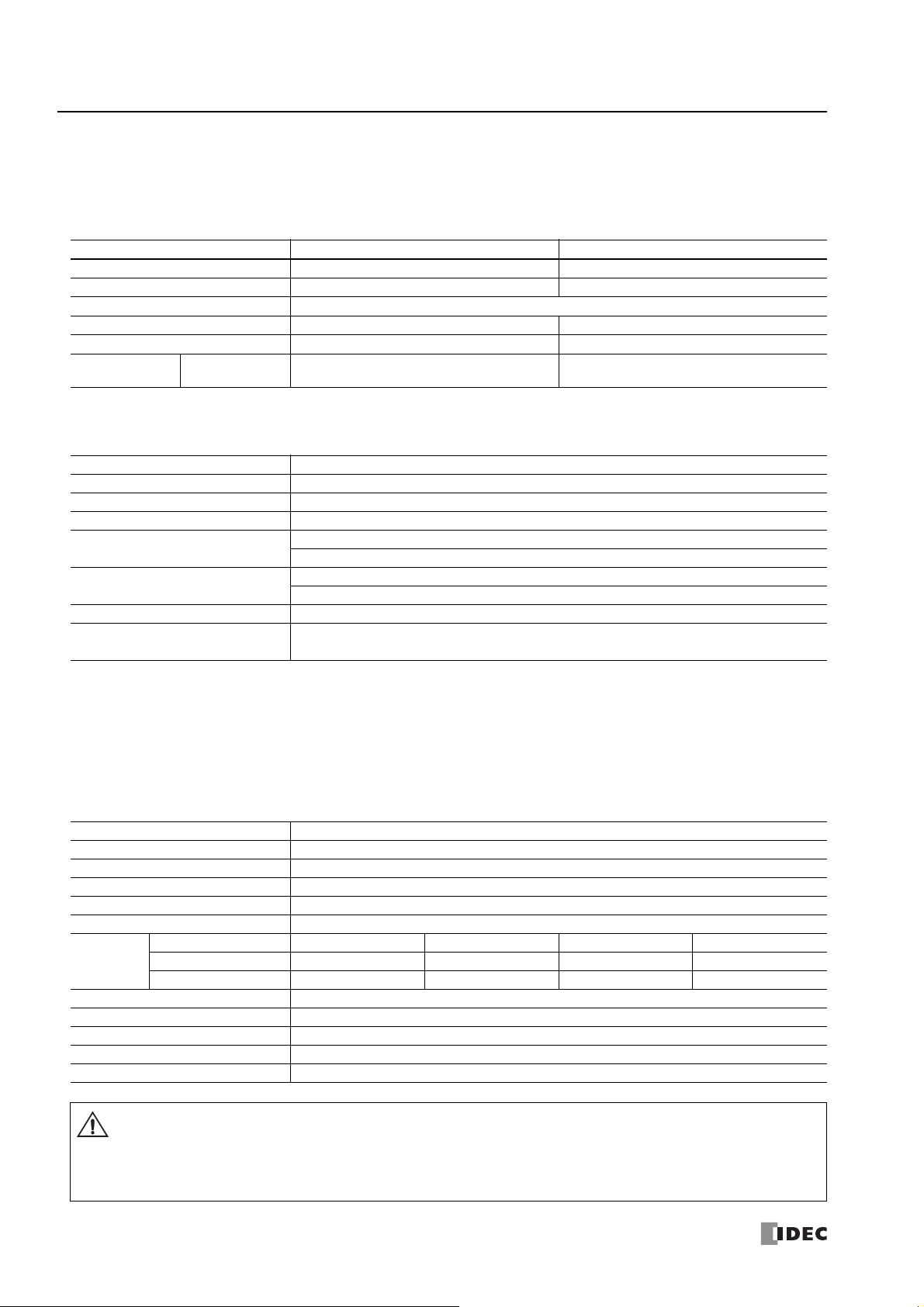
■ 1:N Maintenance Communication System
This example shows a 1:N maintenance communication system in which three FC6A Series MicroSmart and a computer are
connected over Ethernet. The Ethernet cables are connected to the Ethernet port 1 of three FC6A Series MicroSmart, and those
FC6A Series MicroSmart are connected to the computer via an Ethernet hub.
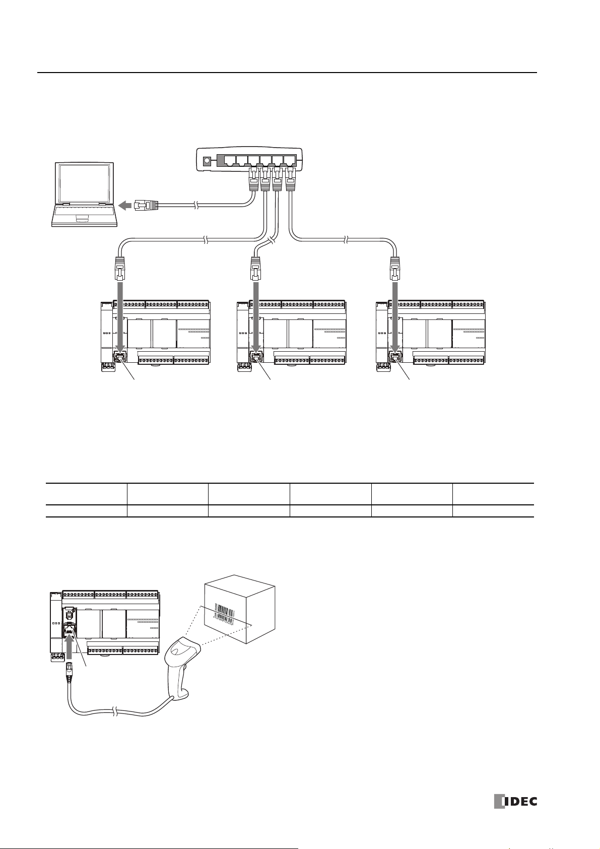
User Communication
The user communication of the FC6A Series MicroSmart enables you to control external devices such as computers, printers, and
barcode readers. For details on user communication, see "User Communication Instructions" on page 5-1.
Supported ports
USB Port Serial Port 1 Ethernet Port 1
■ User Communication Using Serial Port 1
This example shows a system in which a FC6A Series MicroSmart receives the data read by a barcode reader. A barcode reader is
connected to port 1 of the FC6A Series MicroSmart.
Communication
Cartridge
No Ye s Yes Yes N o No
CAN Port
HMI-Ethernet
Port
1-6 FC6A S
ERIES MICROSMART ALL-IN-ONE TYPE COMMUNICATION MANUAL
FC9Y-B1730
1: G
INVERTER
RUN
RVS
ALM
COM
Temperature Controller
Inverter
Serial Port 1
(Port 1)
FC6A Series MicroSmart
FC6A Series MicroSmart
(Slave Station 1)
FC6A Series MicroSmart
(Slave Station 31)
Serial Port 1
(Port 1)
FC6A Series MicroSmart
(Master Station)
ENERAL INFORMATION
Modbus Communication
The FC6A Series MicroSmart is compliant with Modbus RTU protocol and can be used as either a Modbus communication master or
slave. With Modbus communication, the FC6A Series MicroSmart can monitor and modify the data of inverters and temperature
controllers.
For details on Modbus communication, see "Modbus Communication" on page 6-1.
Supported ports
USB Port Serial Port 1 Ethernet Port 1
Communication
Cartridge
CAN Port
HMI-Ethernet
Port
No Ye s Yes Yes N o No
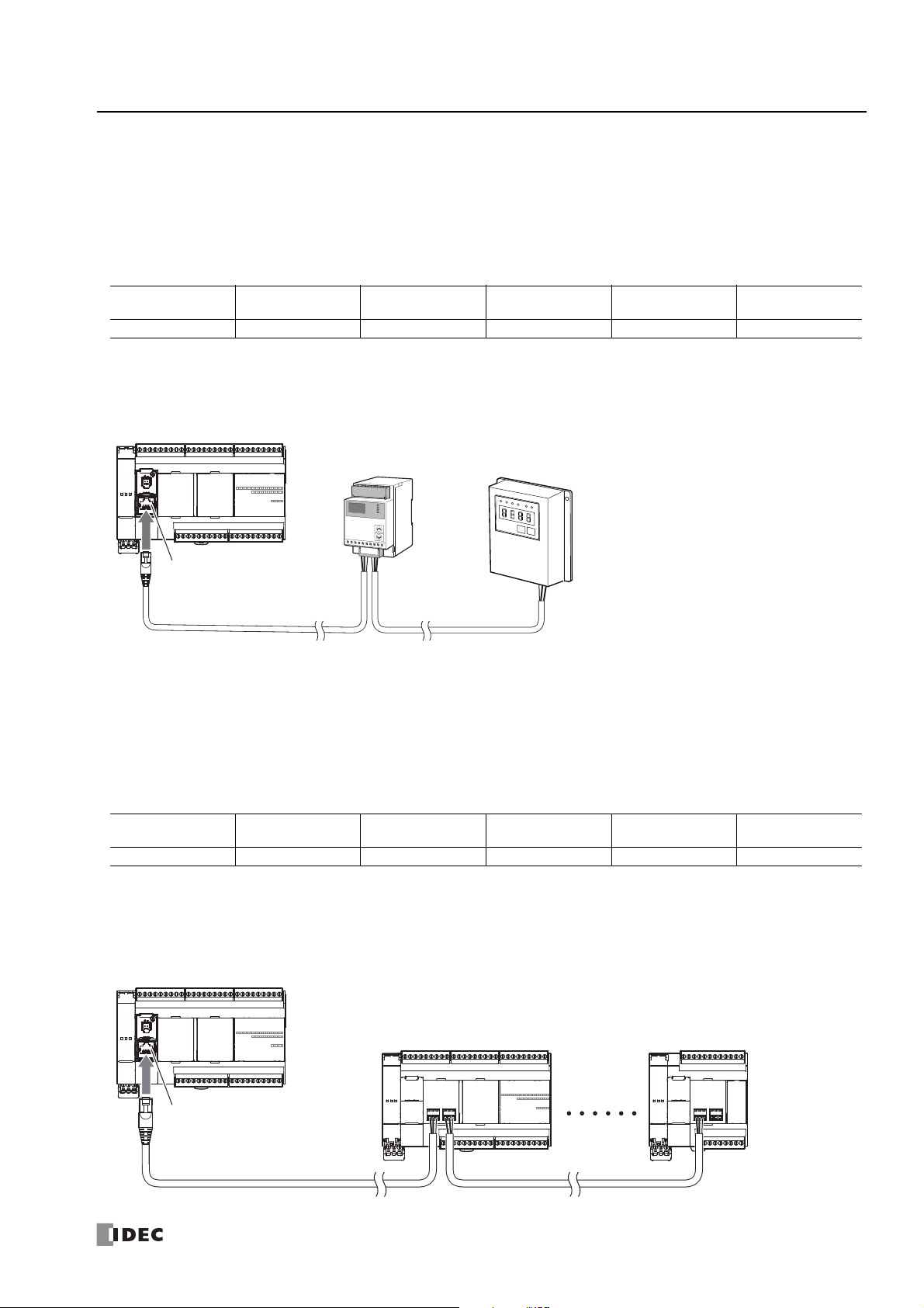
■ Modbus RTU Communication Using Serial Port 1
This example shows a system in which a FC6A Series MicroSmart is communicating with a temperature controller and an inverter
that support Modbus RTU. The A temperature controller is connected to port 1 of the FC6A Series MicroSmart.
Data Link System
The FC6A Series MicroSmart supports data link communication, and it can share data between CPU modules using serial port 1
and cartridge slots. The FC6A Series MicroSmart can also share data with FC5A Series and FC4A Series CPU modules. Configure
the settings in WindLDR to enable distributed control of a maximum of 31 CPU modules.
For details about the data link communication, see "Data Link Communication" on page 7-1.
Supported ports
■ Data Link Communication Using Serial Port 1
This example shows communication between multiple CPU modules with the FC6A Series MicroSmart as the master station. A
slave station CPU module is connected to port 1 of the FC6A Series MicroSmart.
USB Port Serial Port 1 Ethernet Port 1
Communication
Cartridge
CAN Port
No Yes No Yes No No
FC6A S
ERIES MICROSMART ALL-IN-ONE TYPE COMMUNICATION MANUAL
FC9Y-B1730 1-7
HMI-Ethernet
Port
1: G
Engine
FC6A Series MicroSmart
(CAN J1939 All-in-One Type)
CAN Port
CAN
ENERAL INFORMATION
Using J1939 Communication
The CAN J1939 All-in-One Type can be connected to a J1939 communication network using the CAN port and it can communicate
with other J1939 communication-compatible devices. Messages that conform to the SAE J1939 standard can be sent and received.
For details on J1939 communication, see "J1939 Communication" on page 8-1.
Supported ports
USB Port Serial Port 1 Ethernet Port 1
No No No No Yes No
Communication
Cartridge
CAN Port
HMI-Ethernet
Port
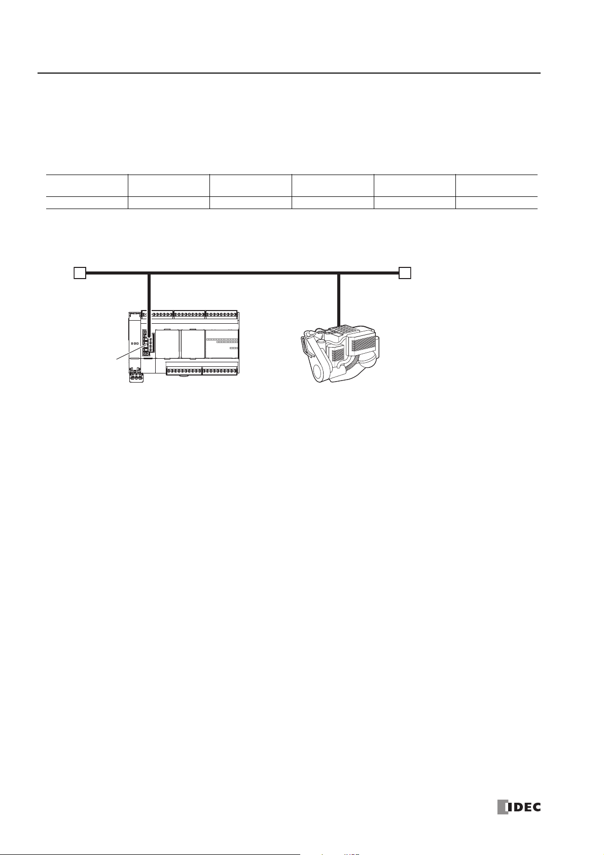
■ CAN Port Usage Example
This example shows the FC6A Series MicroSmart communicating with a J1939-compatible engine. The CAN port of the CAN J1939
All-in-One Type is connected to the engine.
1-8 FC6A S
ERIES MICROSMART ALL-IN-ONE TYPE COMMUNICATION MANUAL
FC9Y-B1730

2: D
EVICE
This chapter provides detailed descriptions of the allocations of devices such as inputs, outputs, internal relays, registers, timers,
and counters that are used in the basic and advanced instructions, as well as details about the allocations of special internal relays
and special data registers.
Please use this chapter as a reference when entering and editing devices in the user program.
Note: The entry and operation of FC6A Series MicroSmart user programs requires specialist knowledge.
Take the time to develop a thorough understanding of the contents and programs in this manual before using the FC6A Series MicroSmart.
Device Addresses
Device Symbol Unit
*1
Inputs
Expansion Input Relays
*1
Output
Expansion Outputs
Internal Relay
Special Internal Relay
Shift Register R Bit
Timer T Bit/Word
Counter C Bit/Word
Data Register D Bit/Word
Special Data Register D Bit/Word
*1 The least significant digit of the device address is an octal number (0 to 7).
*2 I190 to I507 and Q190 to Q507 are devices that can only be used when an expansion module (expansion interface side) is connected using the
expansion interface module.
*3 I310 to I627 and Q310 to Q627 are devices that can only be used when an expansion module (expansion interface side) is connected using the
expansion interface module.
*1
*1
*1*3
*1
IBit
IBit
QBit
QBit
MBit
MBit
16-I/O Type 24-I/O Type 40-I/O Type
I0 - I10
(9 points)
I30 - I187
(128 points)
I190 - I507
(256 points)
(7 points)
Q30 - Q187
(128 points)
Q190 - Q507
(256 points)
*2
Q0 - Q6
*2
Range (Points)
I0 - I15
(14 points)
(224 points)
I310 - I627
(256 points)
Q0 - Q11
(10 points)
Q30 - Q307
(224 points)
Q310 - Q627
(256 points)
M0 - M7997
(6,400 points)
M10000 - M17497
(6,000 points)
M8000 - M8317
(256 points)
R0 - R255
(256 points)
T0 - T1023
(1,024 points)
C0 - C511
(512 points)
D0000 - D7999
(8,000 points)
D10000 to D55999
(46,000 points)
D8000 - D8499
(500 points)
I0 - I27
(24 points)
I30 - I307
*3
Q0 - Q17
(16 points)
*3
FC6A S
ERIES MICROSMART ALL-IN-ONE TYPE COMMUNICATION MANUAL
FC9Y-B1730 2-1

2: D
EVICE
■ Inputs (I), Expansion Inputs (I)
Devices that input on/off information from external devices to the FC6A Series MicroSmart.
■ Outputs (Q), Expansion Outputs (Q)
Devices that output on/off information from the FC6A Series MicroSmart to external devices.
■ Internal Relays (M)
Bit devices used internally on the FC6A Series MicroSmart.
■ Special Internal Relays (M)
Bit devices used internally on the FC6A Series MicroSmart. Special functions are assigned to each bit.
■ Shift Registers (R)
Bit devices that are used with the SFR instruction and the SFRN instruction. The bit sequence of the data is shifted according to
pulse input.
■ Timer (T)
Timers used internally in the FC6A Series MicroSmart. There are three devices: Timer bits (symbol: T, unit: bit), timer preset
values (symbol: TP, unit: word), and timer current values (symbol: TC, unit: word).
These can be used as an on-delay timer or an off-delay timer. For details on timers (T), see Chapter 3 "Using Timer or Counter
as Source Device" in the "FC6A Series MicroSmart LAD Programming Manual".
■ Counters (C)
Counters used internally in the FC6A Series MicroSmart. There are three devices: Counter bits (symbol: C, unit: bit), counter
preset values (symbol: CP, unit: word), and counter current values (symbol: CC, unit: word). These can be used as an adding
counter or a reversible counter. For details on counters (C), see Chapter 3 "Using Timer or Counter as Source Device" in the
"FC6A Series MicroSmart LAD Programming Manual".
■ Data Registers (D)
Word devices that are used for writing numerical data internally in the FC6A Series MicroSmart. These can also be used as bit
devices.
■ Special Data Registers (D)
Word devices that are used for writing numerical data internally in the FC6A Series MicroSmart. Special functions are assigned to
each data register. These can also be used as bit devices.
Notes:
• Although the device symbol for internal relays (M0000 to M7997, M10000 to M17497) and special internal relays (M8000 to M8317) is the
same ("M"), the device characteristics are different. Special functions are assigned to each bit of the special internal relays.
• Although the device symbol for the data registers (D0000 to D7999, D10000 to D55999) and special data registers (D8000 to D8499) is the
same ("D"), the device characteristics are different. Special functions are assigned to each special data register.
2-2 FC6A S
ERIES MICROSMART ALL-IN-ONE TYPE COMMUNICATION MANUAL
FC9Y-B1730
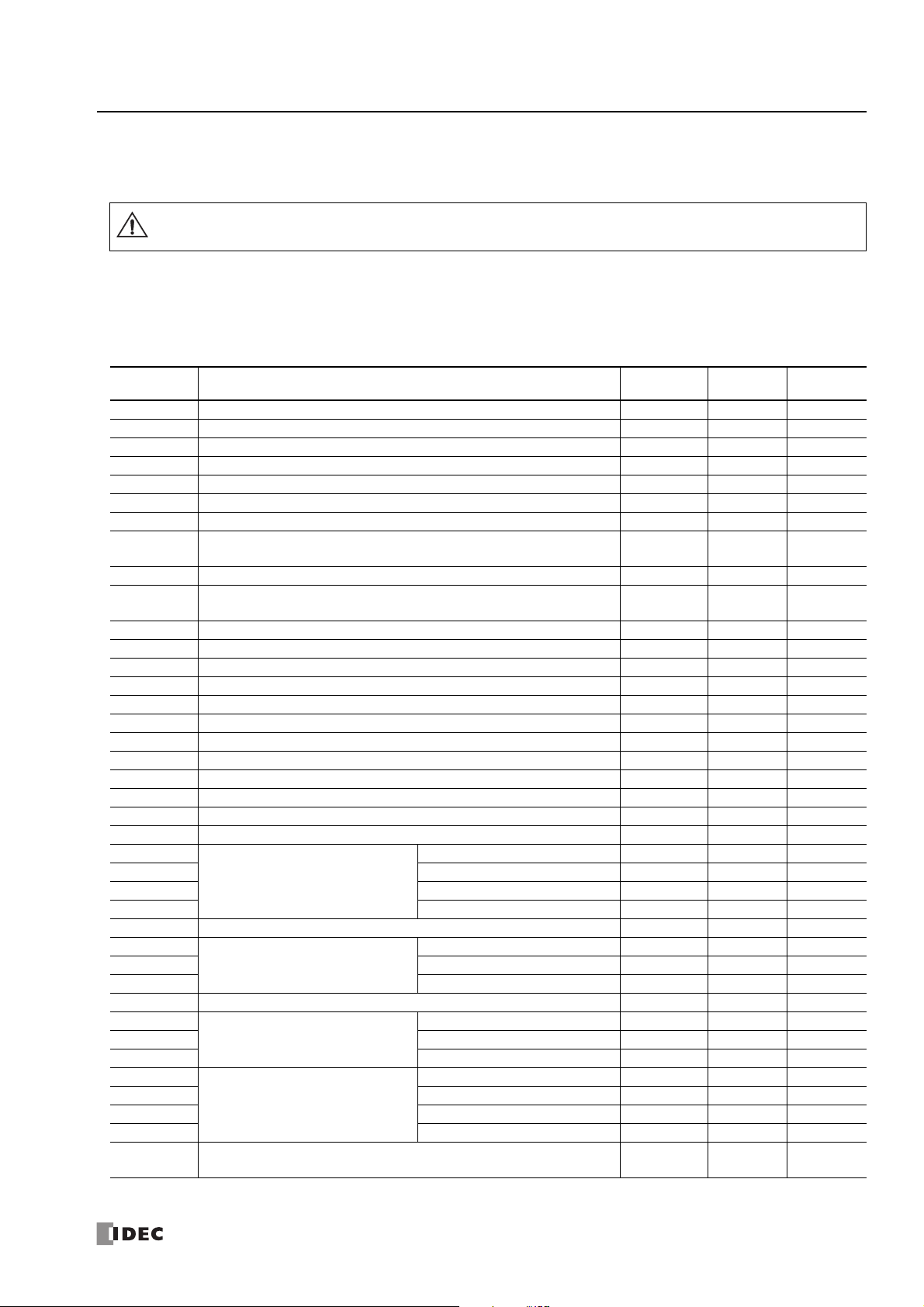
Special Internal Relay
Warning
Special Internal Relay Device Addresses
Do not write to data in the area marked as reserved in the special internal relays list. Otherwise the system may not operate
correctly.
Note: R/W is an abbreviation for read/write.
The notation for the R/W field is as follows.
R/W: The device can be both read from and written to
R: Read-only
W: Write-only
2: D
EVICE
Device
Address
M8000 Start Control Maintained Maintained R/W
M8001 1-s Clock Reset Cleared Cleared R/W
M8002 All Outputs OFF Cleared Cleared R/W
M8003 Carry (Cy) or Borrow (Bw) Cleared Cleared R/W
M8004 User Program Execution Error Cleared Cleared R/W
M8005 Communication Error Maintained Cleared R/W
M8006 Communication Prohibited Flag (When Data Link Master) Maintained Maintained R/W
M8007
M8010 Status LED Operation Operating Cleared R/W
M8011
M8012
M8013 Calendar/Clock Data Write/Adjust Error Flag Operating Cleared R/W
M8014 Calendar/Clock Data Read Error Flag Operating Cleared R/W
M8015 — Reserved — — — —
M8016 Calendar Data Write Flag Operating Cleared R/W
M8017 Clock Data Write Flag Operating Cleared R/W
M8020 Calendar/Clock Data Write Flag Operating Cleared R/W
M8021 Clock Data Adjust Flag Operating Cleared R/W
M8022 User Communication Receive Instruction Cancel Flag (Port 1) Cleared Cleared R/W
M8023 User Communication Receive Instruction Cancel Flag (Port 2) Cleared Cleared R/W
M8024 BMOV/WSFT Executing Flag Maintained Maintained R/W
M8025 Maintain Outputs While Stopped Maintained Cleared R/W
M8026 User Communication Receive Instruction Cancel Flag (Port 3) Cleared Cleared R/W
M8027
M8030 Comparison Output Reset Cleared Cleared R/W
M8031 Gate Input Maintained Cleared R/W
M8032 Reset Input Maintained Cleared R/W
M8033 — Reserved — — — —
M8034
M8035 Gate Input Maintained Cleared R/W
M8036 Reset Input Maintained Cleared R/W
M8037 — Reserved — — — —
M8040
M8041 Gate Input Maintained Cleared R/W
M8042 Reset Input Maintained Cleared R/W
M8043
M8044 Comparison Output Reset Maintained Cleared R/W
M8045 Gate Input Maintained Cleared R/W
M8046 Reset Input Maintained Cleared R/W
M8047
M8050
Initialization Flag (When Data Link Master)/Stop Communication Flag (When
Data Link Slave)
— Reserved — — — —
High-speed Counter (Group 1/I0)
High-speed Counter (Group 3/I3)
High-speed Counter (Group 4/I4)
High-speed Counter (Group 5/I6)
— Reserved — — — —
Description
Count Direction Flag Maintained Cleared R/W
Comparison Output Reset Cleared Cleared R/W
Comparison Output Reset Cleared Cleared R/W
Count Direction Flag Cleared Cleared R/W
When
Stopped
Cleared Cleared R/W
Power
OFF
R/W
FC6A S
ERIES MICROSMART ALL-IN-ONE TYPE COMMUNICATION MANUAL
FC9Y-B1730 2-3

2: D
EVICE
Device
Address
M8051
M8052 Gate Input Maintained Cleared R/W
M8053 Reset Input Maintained Cleared R/W
M8054 Comparison ON Status Maintained Cleared R
M8055 Overflow Maintained Cleared R
M8056 — Reserved — — — —
M8057
M8060 Gate Input Maintained Cleared R/W
M8061 Reset Input Maintained Cleared R/W
M8062 Comparison ON Status Maintained Cleared R
M8063 Overflow Maintained Cleared R
M8064 to
M8067
M8070 SD Memory Card Mount Status Maintained Cleared R
M8071 Accessing SD Memory Card Maintained Cleared R
M8072 Unmount SD Memory Card Operating Cleared R/W
M8073 Function Switch Status Operating Cleared R
M8074 Battery Voltage Measurement Flag Operating Cleared R/W
M8075 to
M8077
M8080 Data Link Slave 1 Communication Completed Relay (When Data Link Master) Operating Cleared R
M8081 Data Link Slave 2 Communication Completed Relay Operating Cleared R
M8082 Data Link Slave 3 Communication Completed Relay Operating Cleared R
M8083 Data Link Slave 4 Communication Completed Relay Operating Cleared R
M8084 Data Link Slave 5 Communication Completed Relay Operating Cleared R
M8085 Data Link Slave 6 Communication Completed Relay Operating Cleared R
M8086 Data Link Slave 7 Communication Completed Relay Operating Cleared R
M8087 Data Link Slave 8 Communication Completed Relay Operating Cleared R
M8090 Data Link Slave 9 Communication Completed Relay Operating Cleared R
M8091 Data Link Slave 10 Communication Completed Relay Operating Cleared R
M8092 Data Link Slave 11 Communication Completed Relay Operating Cleared R
M8093 Data Link Slave 12 Communication Completed Relay Operating Cleared R
M8094 Data Link Slave 13 Communication Completed Relay Operating Cleared R
M8095 Data Link Slave 14 Communication Completed Relay Operating Cleared R
M8096 Data Link Slave 15 Communication Completed Relay Operating Cleared R
M8097 Data Link Slave 16 Communication Completed Relay Operating Cleared R
M8100 Data Link Slave 17 Communication Completed Relay Operating Cleared R
M8101 Data Link Slave 18 Communication Completed Relay Operating Cleared R
M8102 Data Link Slave 19 Communication Completed Relay Operating Cleared R
M8103 Data Link Slave 20 Communication Completed Relay Operating Cleared R
M8104 Data Link Slave 21 Communication Completed Relay Operating Cleared R
M8105 Data Link Slave 22 Communication Completed Relay Operating Cleared R
M8106 Data Link Slave 23 Communication Completed Relay Operating Cleared R
M8107 Data Link Slave 24 Communication Completed Relay Operating Cleared R
M8110 Data Link Slave 25 Communication Completed Relay Operating Cleared R
M8111 Data Link Slave 26 Communication Completed Relay Operating Cleared R
M8112 Data Link Slave 27 Communication Completed Relay Operating Cleared R
M8113 Data Link Slave 28 Communication Completed Relay Operating Cleared R
M8114 Data Link Slave 29 Communication Completed Relay Operating Cleared R
M8115 Data Link Slave 30 Communication Completed Relay Operating Cleared R
M8116 Data Link Slave 31 Communication Completed Relay Operating Cleared R
M8117 Data Link All Slaves Communication Completed Relay Operating Cleared R
M8120 Initialize Pulse Cleared Cleared R
M8121 1-s Clock Operating Cleared R
M8122 100-ms Clock Operating Cleared R
High-speed Counter (Group 2/I1)
High-speed Counter (Group 6/I7)
— Reserved — — — —
— Reserved — — — —
Description
Comparison Output Reset Cleared Cleared R/W
Comparison Output Reset Cleared Cleared R/W
When
Stopped
Power
OFF
R/W
2-4 FC6A S
ERIES MICROSMART ALL-IN-ONE TYPE COMMUNICATION MANUAL
FC9Y-B1730

2: D
EVICE
Device
Address
M8123 10-ms Clock Operating Cleared R
M8124 Timer/Counter Preset Value Changed Maintained Cleared R
M8125 In-operation Output Cleared Cleared R
M8126 1 Scan ON After Run-Time Download Completes Cleared Cleared R
M8127 — Reserved — — — —
M8130
M8131 Comparison ON Status Maintained Cleared R
M8132 — Reserved — — — —
M8133 High-speed Counter (Group 3/I3) Comparison ON Status Maintained Cleared R
M8134 High-speed Counter (Group 4/I4) Comparison ON Status Maintained Cleared R
M8135
M8136 Comparison ON Status Maintained Cleared R
M8137 Interrupt Input I0 Status (Group 1/I0)
M8140 Interrupt Input I1 Status (Group 2/I1) Cleared Cleared R
M8141 Interrupt Input I3 Status (Group 3/I3) Cleared Cleared R
M8142 Interrupt Input I4 Status (Group 4/I4) Cleared Cleared R
M8143 Interrupt Input I6 Status (Group 5/I6) Cleared Cleared R
M8144 Timer Interrupt Status Cleared Cleared R
M8145 to
M8147
M8150 Comparison Result 1 Maintained Cleared R
M8151 Comparison Result 2 Maintained Cleared R
M8152 Comparison Result 3 Maintained Cleared R
M8153
M8154 Group 2/I1 Maintained Cleared R
M8155 Group 3/I3 Maintained Cleared R
M8156 Group 4/I4 Maintained Cleared R
M8157 Group 5/I6 Maintained Cleared R
M8160 Group 6/I7 Maintained Cleared R
M8161
M8162 Underflow Maintained Cleared R
M8163
M8164 Underflow Maintained Cleared R
M8165 High-speed Counter (Group 3/I3) Overflow Maintained Cleared R
M8166 High-speed Counter (Group 4/I4) Overflow Maintained Cleared R
M8167 Interrupt Input I7 Status (Group 6/I7) (ON: Allowed, OFF: Prohibited) Maintained Cleared R
M8170
M8171
M8172
M8173 Group 2 Operating Cleared R
M8174 Group 3 Operating Cleared R
M8175 Group 4 Operating Cleared R
M8176 to
M8183
M8184 Change HMI Module Network Settings Trigger Operating Cleared R/W
M8185 In Daylight Saving Time Period Operating Cleared R
M8186 Executing Auto Ping Operating Cleared R
M8187 Auto Ping Stop Flag Operating Cleared R/W
M8190 Change CPU Module Network Settings Trigger Operating Cleared R/W
M8191 SNTP Acquisition Flag Operating Cleared R/W
High-speed Counter (Group 1/I0)
High-speed Counter (Group 5/I6)
— Reserved — — — —
Catch Input ON/OFF Status
High-speed Counter (Group 1/I0)
High-speed Counter (Group 5/I6)
— Reserved — — — —
Transistor Source Output Overcurrent
Detection
— Reserved — — — —
Description
Reset Status Maintained Cleared R
Reset Status Maintained Cleared R
(ON: Allowed, OFF: Prohibited)
Group 1/I0 Maintained Cleared R
Overflow Maintained Cleared R
Overflow Maintained Cleared R
Group 1 Operating Cleared R
When
Stopped
Cleared Cleared R
Power
OFF
R/W
FC6A S
ERIES MICROSMART ALL-IN-ONE TYPE COMMUNICATION MANUAL
FC9Y-B1730 2-5

2: D
EVICE
Device
Address
M8192 Interrupt Input I0 Edge
M8193 Interrupt Input I3 Edge Cleared Cleared R
M8194 Interrupt Input I4 Edge Cleared Cleared R
M8195 Interrupt Input I6 Edge Cleared Cleared R
M8196 Interrupt Input I7 Edge Cleared Cleared R
M8197 Interrupt Input I1 Edge Cleared Cleared R
M8200
M8201 Connection 2 Cleared Cleared R/W
M8202 Connection 3 Cleared Cleared R/W
M8203 Connection 4 Cleared Cleared R/W
M8204 Connection 5 Cleared Cleared R/W
M8205 Connection 6 Cleared Cleared R/W
M8206 Connection 7 Cleared Cleared R/W
M8207 Connection 8 Cleared Cleared R/W
M8210 — Reserved — — — —
M8211 Send E-mail Server Settings Initialization Operating Cleared R/W
M8212
M8213 Connection 2 Operating Cleared R
M8214 Connection 3 Operating Cleared R
M8215 Connection 4 Operating Cleared R
M8216 Connection 5 Operating Cleared R
M8217 Connection 6 Operating Cleared R
M8220 Connection 7 Operating Cleared R
M8221 Connection 8 Operating Cleared R
M8222
M8223 Connection 2 Operating Cleared R/W
M8224 Connection 3 Operating Cleared R/W
M8225 Connection 4 Operating Cleared R/W
M8226 Connection 5 Operating Cleared R/W
M8227 Connection 6 Operating Cleared R/W
M8230 Connection 7 Operating Cleared R/W
M8231 Connection 8 Operating Cleared R/W
M8232 HMI Module Connection Information Reference Connection Status Operating Cleared R
M8233 to
M8247
M8250 Download from SD Memory Card Execution Flag Operating Cleared R/W
M8251 Upload to SD Memory Card Execution Flag Operating Cleared R/W
M8252 Executing SD Memory Card Download Operating Cleared R
M8253 Executing SD Memory Card Upload Operating Cleared R
M8254 SD Memory Card Download/Upload Execution Completed Output Operating Cleared R
M8255 SD Memory Card Download/Upload Execution Error Output Operating Cleared R
M8256
M8257
M8260 Write Recipe Execution Flag Operating Cleared R/W
M8261 Read Recipe Execution Flag Operating Cleared R/W
M8262 Executing Write Recipe Operating Cleared R/W
M8263 Executing Read Recipe Operating Cleared R/W
M8264 Recipe Execution Completed Output Operating Cleared R/W
M8265 Recipe Execution Error Output Operating Cleared R/W
M8266 to
M8297
M8300 J1939 Communication Permitted Flag Cleared Cleared R/W
M8301 J1939 Online Status Cleared Cleared R
M8302 J1939 Local Station Address Confirmation Status Cleared Cleared R
M8303 J1939 Communication Error Output Cleared Cleared R
User Communication Receive
Instruction Cancel Flag
Connection Status
(ON: Connected, OFF: Not Connected)
Disconnect User Communication
Connection
— Reserved — — — —
— Reserved — — — —
— Reserved — — — —
Description
On: Rising Edge
Off: Falling Edge
Connection 1 Cleared Cleared R/W
Connection 1 Operating Cleared R
Connection 1 Operating Cleared R/W
When
Stopped
Cleared Cleared R
Power
OFF
R/W
2-6 FC6A S
ERIES MICROSMART ALL-IN-ONE TYPE COMMUNICATION MANUAL
FC9Y-B1730

2: D
EVICE
Device
Address
M8304 J1939 Communication Bus Off Occurrence Output Cleared Cleared R
M8305 to
M8310
M8311 ESC+Key Input (Up) ESC+Key Input ( ) Cleared Cleared R
M8312 ESC+Key Input (Down) ESC+Key Input ( ) Cleared Cleared R
M8313 ESC+Key Input (Left) ESC+Key Input ( ) Cleared Cleared R
M8314 ESC+Key Input (Right) ESC+Key Input ( ) Cleared Cleared R
M8315 to
M8317
— Reserved — — — —
— Reserved — — — —
Description
When
Stopped
Power
OFF
R/W
Supplementary Descriptions of the Special Internal Relays Related to the Communication Functions
■ M8005: Communication Error
When an error occurs during data link communication, M8005 is turned on. The state is retained even when the error is cleared.
■ M8006: Communication Prohibited Flag (When Data Link Master)
During data link communication, communication is stopped while M8006 is on.
■ M8007: Initialization Flag (When Data Link Master)/Stop Communication Flag (When Data Link Slave)
When data link master:
When this flag is turned on in the run status, the data link is initialized just once to check the connection
status. Use this when the slave configured in the data link is powered at a timing slower than the master.
When data link slave : This flag is turned on when communication from the master is interrupted for 10 s or longer. This flag is
turned off when communication can be normally received.
■ M8022: User Communication Receive Instruction Cancel Flag (Port 1)
While M8022 is on, user communication (receive instruction) executing on Port 1 is canceled.
■ M8023: User Communication Receive Instruction Cancel Flag (Port 2)
While M8023 is on, user communication (receive instruction) executing on Port 2 is canceled.
■ M8026: User Communication Receive Instruction Cancel Flag (Port 3)
While M8026 is on, user communication (receive instruction) executing on Port 3 is canceled.
■ M8080 to M8117: Data Link Communication Completed Relay
Special internal relays used for data link communication. For details, see "Data Link Communication" on page 7-1.
■ M8184: Change HMI Module Network Settings Trigger
When M8184 is turned on, the values written to D8437 to D8456 are set as the HMI module IP address.
The IP address is not set just by changing the values of D8437 to D8456. For details on changing the HMI module network
settings, see "Network settings by HMI module special data registers" on page 3-5.
■ M8186: Executing Auto Ping
M8186 is on when auto ping is operating. M8186 is off when auto ping is stopped. For details on auto ping, see "Auto Ping
Function" on page 3-18.
■ M8187: Auto Ping Stop Flag
While M8187 is on, auto ping stops. While M8187 is off, auto ping is executed. At that time, auto ping is executed from the
smallest remote host number specified in the remote host list, regardless of the previous end status.
■ M8190: Change CPU Module Network Settings Trigger
When M8190 is turned on, the values written to D8304 to D8323 are set as the CPU module IP address.
The IP address is not set just by changing the values of D8304 to D8323. For details on changing the CPU module network
settings, see "Network settings by special data registers" on page 3-4.
■ M8191: SNTP Acquisition Flag
When M8191 is turned on, the time information is acquired from the SNTP server.
■ M8200 to M8207: User Communication Receive Instruction Cancel Flag
When M8200 to M8207 are turned on, the user communication receive instruction being executed is stopped.
M8200 = User communication receive instruction being executed on client connection 1
M8201 = User communication receive instruction being executed on client connection 2
M8202 = User communication receive instruction being executed on client connection 3
M8203 = User communication receive instruction being executed on client connection 4
M8204 = User communication receive instruction being executed on client connection 5
M8205 = User communication receive instruction being executed on client connection 6
M8206 = User communication receive instruction being executed on client connection 7
M8207 = User communication receive instruction being executed on client connection 8
FC6A S
ERIES MICROSMART ALL-IN-ONE TYPE COMMUNICATION MANUAL
FC9Y-B1730 2-7

2: D
EVICE
■ M8211: Send E-mail Server Settings Initialization
When M8211 is turned on, the send E-mail server settings are initialized.
■ M8212 to M8221: Connection Status
While connected to a network device via the maintenance communication server, user communication server/client, or Modbus
TCP server/client, the connection status is turned on. While not connected to a network device, the connection status is turned
off.
M8212 = Connection 1
M8213 = Connection 2
M8214 = Connection 3
M8215 = Connection 4
M8216 = Connection 5
M8217 = Connection 6
M8220 = Connection 7
M8221 = Connection 8
■ M8222 to M8231: Disconnect User Communication Connection
When connected to a remote host via user communication, the corresponding connection is disconnected when M8222 to
M8231 is turned on.
M8222 = Connection 1
M8223 = Connection 2
M8224 = Connection 3
M8225 = Connection 4
M8226 = Connection 5
M8227 = Connection 6
M8230 = Connection 7
M8231 = Connection 8
These relays are enabled only when a user communication client is used.
■ M8232: HMI Module Connection Information Reference Connection Status
M8232 is turned on when there is a connection with the connection number specified by D8429. M8232 is turned off when there
is no connection.
■ M8300 to M8304: J1939 Communication
Special data registers used in J1939 communication. For details, see "Special Internal Relay Allocations" on page 8-4.
2-8 FC6A S
ERIES MICROSMART ALL-IN-ONE TYPE COMMUNICATION MANUAL
FC9Y-B1730
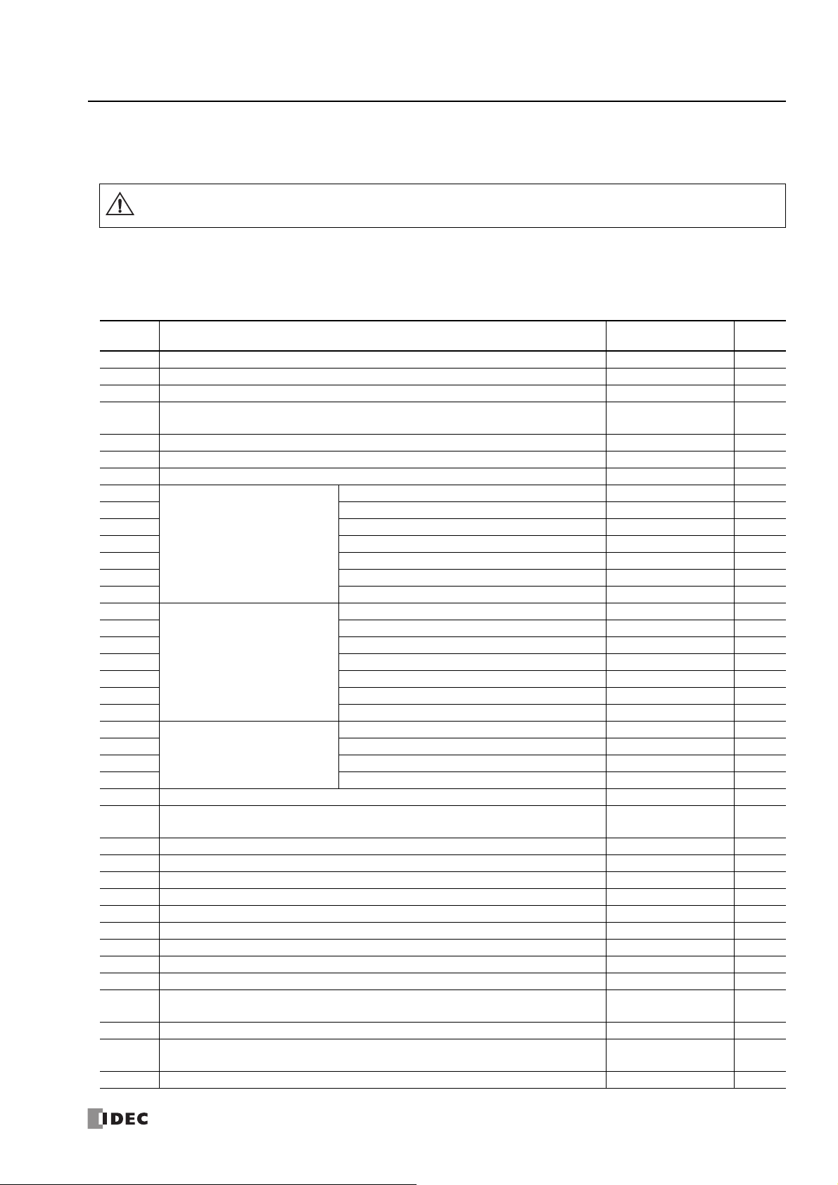
Special Data Register
Warning
Special Data Register Device Addresses
Do not write to data in the area marked as reserved in the special data registers list. Otherwise the system may not operate
correctly.
Note: R/W is an abbreviation for read/write.
The notation for the R/W field is as follows.
R/W: The device can be both read from and written to
R: Read-only
W: Write-only
2: D
EVICE
Device
Address
D8000 Quantity of Inputs When I/O initialized R
D8001 Quantity of Outputs When I/O initialized R
D8002 CPU Module Type Information Power-up R
D8003
D8004
D8005 General Error Code When error occurred R/W
D8006 User Program Execution Error Code When error occurred R
D8007 — Reserved — ― -
D8008
D8009 Month Every 500 ms R
D8010 Day Every 500 ms R
D8011 Day of the Week Every 500 ms R
D8012 Hour Every 500 ms R
D8013 Minute Every 500 ms R
D8014 Second Every 500 ms R
D8015
D8016 Month ― W
D8017 Day ― W
D8018 Day of the Week ― W
D8019 Hour ― W
D8020 Minute ― W
D8021 Second ― W
D8022
D8023 Scan Time Current Value (ms) Every scan R
D8024 Scan Time Maximum Value (ms) At occurrence R
D8025 Scan Time Minimum Value (ms) At occurrence R
D8026 Communication Mode Information (Port 1 to Port 3) Every scan R
D8027
D8028
D8029 System Software Version Power-up R
D8030 Communication Adapter Information Power-up R
D8031 Optional Cartridge Connection Information Power-up R
D8032 Interrupt Input Jump Destination Label No. (I1) ― R/W
D8033 Interrupt Input Jump Destination Label No. (I3) ― R/W
D8034 Interrupt Input Jump Destination Label No. (I4) ― R/W
D8035 Interrupt Input Jump Destination Label No. (I6) ― R/W
D8036 Timer Interrupt Jump Destination Label No. ― R/W
D8037 Number of Connected I/O Modules When I/O initialized R
D8038 to
D8051
D8052 J1939 Communication Error Code Every scan R/W
D8053 to
D8055
D8056 Battery Voltage ― R
— Reserved — ― -
Calendar/Clock Current Data
(Read only)
Calendar/Clock New Data
(Write only)
Scan Time Data
— Reserved — ― -
— Reserved — ――
— Reserved — ――
Description Update Timing R/W
Year Every 500 ms R
Yea r ― W
Constant Scan Time Preset Value (1 to 1,000 ms) ― W
FC6A S
ERIES MICROSMART ALL-IN-ONE TYPE COMMUNICATION MANUAL
FC9Y-B1730 2-9

2: D
EVICE
Device
Address
D8057 Analog Potentiometer (AI0) Every scan R
D8058 Built-in Analog Input (AI1) Every scan R
D8059 Analog Input Status AI0 Every scan R
D8060 Analog Input Status AI1 Every scan R
D8061 to
D8066
D8067 Backlight ON Time ― R/W
D8068 — Reserved — ――
D8069
D8070 Slave 2 Communication Status/Error (When Data Link Master Mode) When error occurred R
D8071 Slave 3 Communication Status/Error (When Data Link Master Mode) When error occurred R
D8072 Slave 4 Communication Status/Error (When Data Link Master Mode) When error occurred R
D8073 Slave 5 Communication Status/Error (When Data Link Master Mode) When error occurred R
D8074 Slave 6 Communication Status/Error (When Data Link Master Mode) When error occurred R
D8075 Slave 7 Communication Status/Error (When Data Link Master Mode) When error occurred R
D8076 Slave 8 Communication Status/Error (When Data Link Master Mode) When error occurred R
D8077 Slave 9 Communication Status/Error (When Data Link Master Mode) When error occurred R
D8078 Slave 10 Communication Status/Error (When Data Link Master Mode) When error occurred R
D8079 Slave 11 Communication Status/Error (When Data Link Master Mode) When error occurred R
D8080 Slave 12 Communication Status/Error (When Data Link Master Mode) When error occurred R
D8081 Slave 13 Communication Status/Error (When Data Link Master Mode) When error occurred R
D8082 Slave 14 Communication Status/Error (When Data Link Master Mode) When error occurred R
D8083 Slave 15 Communication Status/Error (When Data Link Master Mode) When error occurred R
D8084 Slave 16 Communication Status/Error (When Data Link Master Mode) When error occurred R
D8085 Slave 17 Communication Status/Error (When Data Link Master Mode) When error occurred R
D8086 Slave 18 Communication Status/Error (When Data Link Master Mode) When error occurred R
D8087 Slave 19 Communication Status/Error (When Data Link Master Mode) When error occurred R
D8088 Slave 20 Communication Status/Error (When Data Link Master Mode) When error occurred R
D8089 Slave 21 Communication Status/Error (When Data Link Master Mode) When error occurred R
D8090 Slave 22 Communication Status/Error (When Data Link Master Mode) When error occurred R
D8091 Slave 23 Communication Status/Error (When Data Link Master Mode) When error occurred R
D8092 Slave 24 Communication Status/Error (When Data Link Master Mode) When error occurred R
D8093 Slave 25 Communication Status/Error (When Data Link Master Mode) When error occurred R
D8094 Slave 26 Communication Status/Error (When Data Link Master Mode) When error occurred R
D8095 Slave 27 Communication Status/Error (When Data Link Master Mode) When error occurred R
D8096 Slave 28 Communication Status/Error (When Data Link Master Mode) When error occurred R
D8097 Slave 29 Communication Status/Error (When Data Link Master Mode) When error occurred R
D8098 Slave 30 Communication Status/Error (When Data Link Master Mode) When error occurred R
D8099 Slave 31 Communication Status/Error (When Data Link Master Mode) When error occurred R
D8100 Slave Number (Port 1) ― R/W
D8101 — Reserved — ――
D8102 Slave Number (Port 2) ― R/W
D8103 Slave Number (Port 3) ― R/W
D8104 Control Signal Status (Port 1 to 3) Every scan R
D8105 RS232C DSR Input Control Signal Option (Port 1 to 3)
D8106 RS232C DTR Output Control Signal Option (Port 1 to 3)
D8107 to
D8119
D8120
D8121 System Software Version ― R
D8122
D8123 System Software Version ― R
— Reserved — ――
Slave 1 Communication Status/Error (When Data Link Master Mode)
Slave Communication Status/Error (When Data Link Slave Mode)
— Reserved — ――
HMI Module Information
Cartridge Slot 1 Information
Description Update Timing R/W
When error occurred R
When sending/
receiving data
When sending/
receiving data
Typ e I D / S t a tus ― R
Typ e I D / S t a tus ― R
R
R
2-10 FC6A S
ERIES MICROSMART ALL-IN-ONE TYPE COMMUNICATION MANUAL
FC9Y-B1730

2: D
EVICE
Device
Address
D8124
D8125 System Software Version ― R
D8126
D8127 System Software Version ― R
D8128 to
D8169
D8170 Analog Cartridge I/O AI2/AQ2 Every scan R
D8171 Analog Cartridge I/O AI3/AQ3 Every scan R
D8172 Analog Cartridge Status AI2/AQ2 Every scan R
D8173 Analog Cartridge Status AI3/AQ3 Every scan R
D8174 Analog Cartridge I/O AI4/AQ4 Every scan R
D8175 Analog Cartridge I/O AI5/AQ5 Every scan R
D8176 Analog Cartridge Status AI4/AQ4 Every scan R
D8177 Analog Cartridge Status AI5/AQ5 Every scan R
D8178 Analog Cartridge I/O AI6/AQ6 Every scan R
D8179 Analog Cartridge I/O AI7/AQ7 Every scan R
D8180 Analog Cartridge Status AI6/AQ6 Every scan R
D8181 Analog Cartridge Status AI7/AQ7 Every scan R
D8182 to
D8191
D8192
D8193 Low Word Every scan R
D8194 High Word
D8195 Low Word ― R/W
D8196 High Word
D8197 Low Word ― R/W
D8198
D8199 Low Word Every scan R
D8200 High Word
D8201 Low Word ― R/W
D8202 High Word
D8203 Low Word ― R/W
D8204 to
D8209
D8210
D8211 Low Word Every scan R
D8212 High Word
D8213 Low Word ― R/W
D8214 Interrupt Input Jump Destination Label No. (I7) ― R/W
D8215 Interrupt Input Jump Destination Label No. (I0) ― R/W
D8216 High-speed
D8217 Low Word ― R/W
D8218
D8219 Low Word Every scan R
D8220 High Word
D8221 Low Word ― R/W
D8222
D8223 Low Word Every scan R
D8224 High Word
D8225 Low Word ― R/W
D8226
D8227 Low Word Every scan R
D8228 High Word
D8229 Low Word ― R/W
Cartridge Slot 2 Information
Cartridge Slot 3 Information
— Reserved — ――
— Reserved — ――
High Word
High-speed
Counter
(Group 2/I1)
High Word
High-speed
Counter
(Group 6/I7)
— Reserved — ――
High-speed
Counter
(Group 1/I0)
Counter
(Group 1/I0)
High-speed
Counter
(Group 3/I3)
High-speed
Counter
(Group 4/I4)
High-speed
Counter
(Group 5/I6)
High Word
High Word
High Word
High Word
High Word
Description Update Timing R/W
Type ID/Status ― R
Type ID/Status ― R
Current Value/Frequency Measurement (I1) Current
Value
Preset Value
Preset Value
Current Value/Frequency Measurement (I7) Current
Value
Preset Value
Preset Value
Current Value/Frequency Measurement (I0) Current
Value
Preset Value
Preset Value
Current Value/Frequency Measurement (I3) Current
Value
Preset Value
Current Value/Frequency Measurement (I4) Current
Value
Preset Value
Current Value/Frequency Measurement (I6) Current
Value
Preset Value
Every scan R
― R/W
― R/W
Every scan R
― R/W
― R/W
Every scan R
― R/W
― R/W
Every scan R
― R/W
Every scan R
― R/W
Every scan R
― R/W
FC6A S
ERIES MICROSMART ALL-IN-ONE TYPE COMMUNICATION MANUAL
FC9Y-B1730 2-11

2: D
EVICE
Device
Address
D8230
D8231
D8232 High-speed
D8233 Low Word ― R/W
D8234 High-speed
D8235 Low Word ― R/W
D8236 High-speed
D8237 Low Word ― R/W
D8238 — Reserved — ――
D8239 Absolute Position Control Status Every scan R
D8240
D8241 Low Word Every scan R
D8242
D8243 Low Word Every scan R
D8244
D8245 Low Word Every scan R
D8246
D8247 Low Word Every scan R
D8248
D8249
D8250 Read SD Memory Card Capacity Every scan R
D8251 Read SD Memory Card Free Capacity Every scan R
D8252
D8253
D8254 SD Memory Card Download/Upload Execution Information
D8255 SD Memory Card Download/Upload Execution Status
D8256 to
D8359
D8260 Recipe Block Number ― R/W
D8261 Recipe Execution Block Number
D8262 Recipe Execution Channel No.
D8263 Recipe Execution Operation
D8264 Recipe Execution Status
D8265 Recipe Execution Error Information
D8266 to
D8277
D8278
D8279 Connection 5 to 8 ― R
D8280 to
D8283
D8284
D8285 HMI Connection 5 to 8 ― R
D8286 to
D8303
— Reserved — ――
High Word
Counter
(Group 5/I6)
High Word
Counter
(Group 3/I3)
High Word
Counter
(Group 4/I4)
Absolute Position
Counter 1
Absolute Position
Counter 2
Absolute Position
Counter 3
Absolute Position
Counter 4
— Reserved — ――
— Reserved — ――
— Reserved — ――
— Reserved — ――
Communication Mode Information
(Client Connection)
— Reserved — ――
Communication Mode Information
(HMI Connection)
— Reserved — ――
High Word
High Word
High Word
High Word
Description Update Timing R/W
― R/W
Preset Value
― R/W
Preset Value
― R/W
Preset Value
Absolute Position
Absolute Position
Absolute Position
Absolute Position
Connection 1 to 4 ― R
HMI Connection 1 to 4 ― R
Every scan R
Every scan R
Every scan R
Every scan R
When processing has
completed
When processing has
completed
When recipe execution
has completed
When recipe execution
has completed
When recipe execution
has completed
When recipe execution
has completed
When recipe execution
has completed
R
R
R
R
R
R
R
2-12 FC6A S
ERIES MICROSMART ALL-IN-ONE TYPE COMMUNICATION MANUAL
FC9Y-B1730

2: D
EVICE
Device
Address
D8304
D8305 ― W
D8306 ― W
D8307 ― W
D8308
D8309 ― W
D8310 ― W
D8311 ― W
D8312
D8313 ― W
D8314 ― W
D8315 ― W
D8316
D8317 ― W
D8318 ― W
D8319 ― W
D8320
D8321 ― W
D8322 ― W
D8323 ― W
D8324
D8325 Every 1 s R
D8326 Every 1 s R
D8327 Every 1 s R
D8328 Every 1 s R
D8329 Every 1 s R
D8330
D8331 Every 1 s R
D8332 Every 1 s R
D8333 Every 1 s R
D8334
D8335 Every 1 s R
D8336 Every 1 s R
D8337 Every 1 s R
D8338
D8339 Every 1 s R
D8340 Every 1 s R
D8341 Every 1 s R
D8342
D8343 Every 1 s R
D8344 Every 1 s R
D8345 Every 1 s R
D8346
D8347 Every 1 s R
D8348 Every 1 s R
D8349 Every 1 s R
D8350
D8351 Every 1 s R
D8352 Every 1 s R
D8353 Every 1 s R
D8354
D8355 Every 1 s R
D8356 Every 1 s R
D8357 Every 1 s R
CPU Module IP Address (Write-only)
CPU Module Subnet Mask (Write-only)
CPU Module Default Gateway (Write-only)
CPU Module Preferred DNS Server (Write-only)
CPU Module Alternate DNS Server (Write-only)
CPU Module MAC Address (Current Value Read-only)
CPU Module IP Address (Current Value Read-only)
CPU Module Subnet Mask (Current Value Read-only)
CPU Module Default Gateway (Current Value Read-only)
CPU Module Preferred DNS Server (Current Value Read-only)
CPU Module Alternate DNS Server (Current Value Read-only)
Connection 1 Connected IP Address
Connection 2 Connected IP Address
Description Update Timing R/W
― W
― W
― W
― W
― W
Every 1 s R
Every 1 s R
Every 1 s R
Every 1 s R
Every 1 s R
Every 1 s R
Every 1 s R
Every 1 s R
FC6A S
ERIES MICROSMART ALL-IN-ONE TYPE COMMUNICATION MANUAL
FC9Y-B1730 2-13

2: D
EVICE
Device
Address
D8358
D8359 Every 1 s R
D8360 Every 1 s R
D8361 Every 1 s R
D8362
D8363 Every 1 s R
D8364 Every 1 s R
D8365 Every 1 s R
D8366
D8367 Every 1 s R
D8368 Every 1 s R
D8369 Every 1 s R
D8370
D8371 Every 1 s R
D8372 Every 1 s R
D8373 Every 1 s R
D8374
D8375 Every 1 s R
D8376 Every 1 s R
D8377 Every 1 s R
D8378
D8379 Every 1 s R
D8380 Every 1 s R
D8381 Every 1 s R
D8382
D8383 Every 1 s R
D8384 Every 1 s R
D8385 Every 1 s R
D8386 Every 1 s R
D8387 Every 1 s R
D8388
D8389 Every 1 s R
D8390 Every 1 s R
D8391 Every 1 s R
D8392
D8393 Every 1 s R
D8394 Every 1 s R
D8395 Every 1 s R
D8396
D8397 Every 1 s R
D8398 Every 1 s R
D8399 Every 1 s R
D8400
D8401 Every 1 s R
D8402 Every 1 s R
D8403 Every 1 s R
D8404
D8405 Every 1 s R
D8406 Every 1 s R
D8407 Every 1 s R
D8408 to
D8412
D8413 Time Zone Offset ― R/W
D8414 SNTP Operation Status ― R
D8415 SNTP Access Elapsed Time ― R
Connection 3 Connected IP Address
Connection 4 Connected IP Address
Connection 5 Connected IP Address
Connection 6 Connected IP Address
Connection 7 Connected IP Address
Connection 8 Connected IP Address
HMI Module MAC Address (Current Value Read-only)
HMI Module IP Address (Current Value Read-only)
HMI Module Subnet Mask (Current Value Read-only)
HMI Module Default Gateway (Current Value Read-only)
HMI Module Preferred DNS Server (Current Value Read-only)
HMI Module Alternate DNS Server (Current Value Read-only)
— Reserved — ――
Description Update Timing R/W
Every 1 s R
Every 1 s R
Every 1 s R
Every 1 s R
Every 1 s R
Every 1 s R
Every 1 s R
Every 1 s R
Every 1 s R
Every 1 s R
Every 1 s R
Every 1 s R
2-14 FC6A S
ERIES MICROSMART ALL-IN-ONE TYPE COMMUNICATION MANUAL
FC9Y-B1730

2: D
EVICE
Device
Address
D8416 to
D8428
D8429
D8430
D8431 Every 1 s R
D8432 Every 1 s R
D8433 Every 1 s R
D8434 Connected Port No. Every 1 s R
D8435
D8436
D8437
D8438 ― W
D8439 ― W
D8440 ― W
D8441
D8442 ― W
D8443 ― W
D8444 ― W
D8445
D8446 ― W
D8447 ― W
D8448 ― W
D8449
D8450 ― W
D8451 ― W
D8452 ― W
D8453
D8454 ― W
D8455 ― W
D8456 ― W
D8457 EMAIL Instruction Detailed Error Information ― R
D8458 to
D8469
D8470
D8471 System Software Version ― R
D8472
D8473 System Software Version ― R
D8474
D8475 System Software Version ― R
D8476
D8477 System Software Version ― R
D8478
D8479 System Software Version ― R
D8480
D8481 System Software Version ― R
D8482
D8483 System Software Version ― R
D8484
D8485 System Software Version ― R
D8486
D8487 System Software Version ― R
D8488
D8489 System Software Version ― R
D8490
D8491 System Software Version ― R
— Reserved — ――
HMI Module Connection
Information Reference
— Reserved — ――
HMI Module IP Address (Write-only)
HMI Module Subnet Mask (Write-only)
HMI Module Default Gateway (Write-only)
HMI Module Preferred DNS Server (Write-only)
HMI Module Alternate DNS Server (Write-only)
— Reserved — ――
Expansion Module Slot 1
Information
Expansion Module Slot 2
Information
Expansion Module Slot 3
Information
Expansion Module Slot 4
Information
Expansion Module Slot 5
Information
Expansion Module Slot 6
Information
Expansion Module Slot 7
Information
Expansion Module Slot 8
Information
Expansion Module Slot 9
Information
Expansion Module Slot 10
Information
Expansion Module Slot 11
Information
Description Update Timing R/W
Connection No. ― R/W
Every 1 s R
Connected IP Address
― W
― W
― W
― W
― W
Type ID/Status ― R
Type ID/Status ― R
Type ID/Status ― R
Type ID/Status ― R
Type ID/Status ― R
Type ID/Status ― R
Type ID/Status ― R
Type ID/Status ― R
Type ID/Status ― R
Type ID/Status ― R
Type ID/Status ― R
FC6A S
ERIES MICROSMART ALL-IN-ONE TYPE COMMUNICATION MANUAL
FC9Y-B1730 2-15

2: D
Bit
15
Bit
0
Bit
7
Bit
8
Bit
4
Port 1
Port 2
Port 3
Bit
3
Bit
11
0 (0000): Maintenance communication
1 (0001): User communication
2 (0010): Modbus RTU master
3 (0011): Modbus RTU slave
4 (0100): Data link communication
Bit
15
Bit
0
Bit
7
Bit
8
Bit
1
Bit
2
Bit
3
Port 2
Port 3
0 (00): No communication cartridges
1 (01): RS-232C communication cartridge
2 (10): RS-485 communication cartridge
3 (11): Free
EVICE
Device
Address
D8492
D8493 System Software Version ― R
D8494
D8495 System Software Version ― R
D8496
D8497 System Software Version ― R
D8498
D8499 System Software Version ― R
Expansion Module Slot 12
Information
Expansion Module Slot 13
Information
Expansion Module Slot 14
Information
Expansion Module Slot 15
Information
Description Update Timing R/W
Typ e I D / S t a tus ― R
Typ e I D / S t a tus ― R
Typ e I D / S t a tus ― R
Typ e I D / S t a tus ― R
Supplementary Descriptions of the Special Data Registers Related to the Communication Functions
■ D8026: Communication Mode Information (Port 1 to 3)
This register indicates communication mode information for Port 1 to Port 3.
The allocation of communication ports in the device (bit assignment) is as follows.
■ D8030: Communication Adapter Information
This register indicates information about the communication cartridges in Port 2 and Port 3.
The allocation of communication ports in the device (bit assignment) is as follows.
■ D8052: J1939 Communication Error Code
When an error occurs in J1939 communication, the error code is written to this register. For details on J1939 communication
error codes, see "J1939 Communication Error Code (D8052)" on page 8-5.
■ D8069 to D8099: Slave (1 to 31) Communication Status/Error
Special data registers used in data link communication. For details, see "Master Station" on page 7-4.
■ D8100, D8102, D8103: Slave Number (Port 1 to 3)
The slave number is written to these registers when the Port 1 to 3 communication mode is maintenance communication,
Modbus RTU slave, or data link communication. The slave number can be changed by changing the value of D8100, D8102, and
D8103 in Function Area Settings
D8100 = Port 1 Slave No.
D8102 = Port 2 Slave No.
D8103 = Port 3 Slave No.
For details on communication modes, see the following in this manual.
• Maintenance communication: "Maintenance Communication" on page 4-1
• Modbus RTU slave: "Modbus Communication" on page 6-1
• Data link communication: "Data Link Communication" on page 7-1
2-16 FC6A S
ERIES MICROSMART ALL-IN-ONE TYPE COMMUNICATION MANUAL
FC9Y-B1730

2: D
Port 1
Port 2
Port 3
Bit
15
Bit
0
Bit
7
Bit
8
12 3 45
0 (00): DTR and DSR are both off.
1 (01): DTR is off and DSR is on.
2 (10): DTR is on and DSR is off.
3 (11): DTR and DSR are both on.
ON
OFF
Not possible Not possiblePossible
DSR signal
Transmit/receive
ON
OFF
Not possible Not possiblePossible
DSR signal
Transmit/receive
ON
OFF
Not possible Not possiblePossible
DSR signal
Tra ns mit
Not possible Not possiblePossible
DSR signal
ON
OFF
Tra ns mit
■ D8104: Control Signal Status (Port 1 to 3)
The signal statuses of the DSR and DTR controls lines are written to this register. This register is updated in END processing
when stopped and while running. The allocation of communication ports in the device (bit assignment) is as follows.
■ D8105: RS232C DSR Input Control Signal Option (Port 1 to 3)
The signal statuses of the DSR and DTR controls lines are written to this register. This register is updated in END processing
when stopped and while running. The allocation of communication ports in the device (bit assignment) is as follows.
Bit
15
Bit
8
Bit
5
6
Bit
4
3
Bit
1
07
2
Port 1
Port 2
Port 3
EVICE
0 (000): The DSR signal status is not used for FC6A Series MicroSmart transmission control.
Use this status when DSR signal control is not required.
1 (001): When the DSR signal is on, the FC6A Series MicroSmart can transmit and receive.
2 (010): When the DSR signal is off, the FC6A Series MicroSmart can transmit and receive.
3 (011): When the DSR signal is on, transmission is possible (reception is always possible).
This is normally called "busy control" and is used for transmission control for devices with a slow
processing speed such as printers.
(As viewed from the connected device, there is a limit on the data that can be input.)
4 (100): When the DSR signal is off, transmission is possible.
5 or higher: The operation is the same as the setting "000".
FC6A S
ERIES MICROSMART ALL-IN-ONE TYPE COMMUNICATION MANUAL
FC9Y-B1730 2-17

2: D
Port 1
Port 2
Port 3
Bit
15
Bit
0
Bit
7
Bit
8
1Bit 2
3
Bit 4
5
Running RunningStopped
DTR signal
ON
OFF
Not possible Not possiblePossible
DTR signal
ON
OFF
Receive
EVICE
■ D8106: RS232C DTR Output Control Signal Option (Port 1 to 3)
This register is used when indicating the FC6A Series MicroSmart control status and the transmit/receive status to the connected
device. This control line is an output signal from the FC6A Series MicroSmart to the connected device. This register is only valid
during user communication.
The allocation of communication ports in the device (bit assignment) is as follows.
0 (00): The signal is on when the FC6A Series MicroSmart is set to run and off when stopped.
While running, the signal is always on regardless of transmitting or receiving data. Set this value when it is
necessary to indicate the run status.
1 (01): Always off.
2 (10): Set this value when performing flow control for received data. The signal is on when data from the
connected device can be received.
The signal is off when data cannot be received.
3 (11): The operation is the same as the setting "0".
■ D8278, D8279: Communication Mode Information (Client Connection) (Connection 1 to 8)
D8278 = Indicates the communication mode of connections 1 through 4.
D8279 = Indicates the communication mode of connections 5 through 8.
The allocation of connections in the device (bit assignment) is as follows.
D8278
D8279
Bit
15
Bit
15
Bit
Bit
7
8
Bit
Bit
7
8
• Client connection (most significant bit = 0)
Bit
0
Bit
0
Connection 1
Connection 2
Connection 3
Connection 4
Connection 5
Connection 6
Connection 7
Connection 8
0000: Unused
0001: User Communication
0010: Modbus TCP client
• Server connection (most significant bit = 1)
1000: Maintenance Communication
1001: User Communication
1010: Modbus TCP server
2-18 FC6A S
ERIES MICROSMART ALL-IN-ONE TYPE COMMUNICATION MANUAL
FC9Y-B1730

■ D8284, D8285: Communication Mode Information (HMI Connection) (HMI Connection 1 to 8)
Bit
15
Bit
0
Bit
7
Bit
8
HMI Connection 1
HMI Connection 2
HMI Connection 3
HMI Connection 4
D8284
Bit
15
Bit
0
Bit
7
Bit
8
HMI Connection 5
HMI Connection 6
HMI Connection 7
HMI Connection 8
D8285
D8284: Indicates the communication mode of HMI connections 1 through 4.
D8285: Indicates the communication mode of HMI connections 5 through 8.
The allocation of connections in the device (bit assignment) is as follows.
• Client connection (most significant bit = 0)
0000: Unused
• Server connection (most significant bit = 1)
1000: Maintenance Communication
2: D
EVICE
■ D8304 to D8307: CPU Module IP Address (Write-only)
These registers are used to write the CPU module's IP address.
IP address: To set as aaa.bbb.ccc.ddd, write the following.
D8304=aaa, D8305=bbb, D8306=ccc, D8307=ddd
■ D8308 to D8311: CPU Module Subnet Mask (Write-only)
These registers are used to write the CPU module's subnet mask.
Subnet mask: For aaa.bbb.ccc.ddd, write the following.
D8308=aaa, D8309=bbb, D8310=ccc, D8311=ddd
■ D8312 to D8315: CPU Module Default Gateway (Write-only)
These registers are used to write the CPU module's default gateway.
Default gateway: For aaa.bbb.ccc.ddd, write the following.
D8312=aaa, D8313=bbb, D8314=ccc, D8315=ddd
■ D8316 to D8319: CPU Module Preferred DNS Server (Write-only)
These registers are used to write the CPU module's preferred DNS server.
Preferred DNS server: For aaa.bbb.ccc.ddd, write the following.
D8316=aaa, D8317=bbb, D8318=ccc, D8319=ddd
■ D8320 to D8323: CPU Module Alternate DNS Server (Write-only)
These registers are used to write the CPU module's alternate DNS server.
Alternate DNS server: For aaa.bbb.ccc.ddd, write the following.
D8320=aaa, D8321=bbb, D8322=ccc, D8323=ddd
FC6A S
ERIES MICROSMART ALL-IN-ONE TYPE COMMUNICATION MANUAL
FC9Y-B1730 2-19

2: D
EVICE
■ D8324 to D8329: CPU Module MAC Address (Current Value Read-only)
The CPU module's MAC address is written to the special data registers as follows.
Example: MAC address: AA-BB-CC-DD-EE-FF
D8324=AA, D8325=BB, D8326=CC, D8327=DD, D8328=EE, D8329=FF
■ D8330 to D8333: CPU Module IP Address (Current Value Read-only)
The CPU module's IP address is written to the special data registers as follows.
Example: The CPU module's own IP address aaa.bbb.ccc.ddd
D8330=aaa, D8331=bbb, D8332=ccc, D8333=ddd
■ D8334 to D8337: CPU Module Subnet Mask (Current Value Read-only)
The CPU module's subnet mask value is written to the special data registers as follows.
Example: Subnet mask: aaa.bbb.ccc.ddd
D8334=aaa, D8335=bbb, D8336=ccc, D8337=ddd
■ D8338 to D8341: CPU Module Default Gateway (Current Value Read-only)
The CPU module's default gateway address is written to the special data registers as follows.
Example: Default gateway: aaa.bbb.ccc.ddd
D8338=aaa, D8339=bbb, D8340=ccc, D8341=ddd
■ D8342 to D8345: CPU Module Preferred DNS Server (Current Value Read-only)
The CPU module's preferred DNS server address is written to the special data registers as follows.
Example: Preferred DNS server: aaa.bbb.ccc.ddd
D8342=aaa, D8343=bbb, D8344=ccc, D8345=ddd
■ D8346 to D8349: CPU Module Alternate DNS Server (Current Value Read-only)
The CPU module's alternate DNS server address is written to the special data registers as follows.
Example: Alternate DNS server: aaa.bbb.ccc.ddd
D8346=aaa, D8347=bbb, D8348=ccc, D8349=ddd
■ D8350 to D8381: Connection Connected IP Address
The IP address of the connected device that is being accessed through a connection is written as follows.
Connection 1 Connected IP Address: For aaa.bbb.ccc.ddd
D8350=aaa, D8351=bbb, D8352=ccc, D8353=ddd
Connection 2 Connected IP Address: For aaa.bbb.ccc.ddd
D8354=aaa, D8355=bbb, D8356=ccc, D8357=ddd
Connection 3 Connected IP Address: For aaa.bbb.ccc.ddd
D8358=aaa, D8359=bbb, D8360=ccc, D8361=ddd
Connection 4 Connected IP Address: For aaa.bbb.ccc.ddd
D8362=aaa, D8363=bbb, D8364=ccc, D8365=ddd
Connection 5 Connected IP Address: For aaa.bbb.ccc.ddd
D8366=aaa, D8367=bbb, D8368=ccc, D8369=ddd
Connection 6 Connected IP Address: For aaa.bbb.ccc.ddd
D8370=aaa, D8371=bbb, D8372=ccc, D8373=ddd
Connection 7 Connected IP Address: For aaa.bbb.ccc.ddd
D8374=aaa, D8375=bbb, D8376=ccc, D8377=ddd
Connection 8 Connected IP Address: For aaa.bbb.ccc.ddd
D8378=aaa, D8379=bbb, D8380=ccc, D8381=ddd
■ D8382 to D8387: HMI Module MAC Address (Current Value Read-only)
The MAC address is written to the special data registers as follows.
Example: MAC address: AA-BB-CC-DD-EE-FF
D8382=AA, D8383=BB, D8384=CC, D8385=DD, D8386=EE, D8387=FF
■ D8388 to D8391: HMI Module IP Address (Current Value Read-only)
The HMI module's IP address is written to the special data registers as follows.
Example: HMI module IP address: aaa.bbb.ccc.ddd
D8388=aaa, D8389=bbb, D8390=ccc, D8391=ddd
2-20 FC6A S
ERIES MICROSMART ALL-IN-ONE TYPE COMMUNICATION MANUAL
FC9Y-B1730

2: D
■ D8392 to D8395: HMI Module Subnet Mask (Current Value Read-only)
The HMI module's subnet mask value is written to the special data registers as follows.
Example: HMI module subnet mask: aaa.bbb.ccc.ddd
D8392=aaa, D8393=bbb, D8394=ccc, D8395=ddd
■ D8396 to D8399: HMI Module Default Gateway (Current Value Read-only)
The HMI module's default gateway address is written to the special data registers as follows.
Example: HMI module default gateway: aaa.bbb.ccc.ddd
D8396=aaa, D8397=bbb, D8398=ccc, D8399=ddd
■ D8400 to D8403: HMI Module Preferred DNS Server (Current Value Read-only)
The HMI module's preferred DNS server address is written to the special data registers as follows.
Example: HMI module preferred DNS server: aaa.bbb.ccc.ddd
D8400=aaa, D8401=bbb, D8402=ccc, D8403=ddd
■ D8404 to D8407: HMI Module Alternate DNS Server (Current Value Read-only)
The HMI module's alternate DNS server address is written to the special data registers as follows.
Example: HMI module alternate DNS server: aaa.bbb.ccc.ddd
D8404=aaa, D8405=bbb, D8406=ccc, D8407=ddd
■ D8413: Time Zone Offset
The time zone configured in the function area settings can be finely adjusted in 15-minute increments.
For details, see "SNTP Settings" on page 3-8.
■ D8414: SNTP Operation Status
The operation status is written to this register when the time information is acquired through operation of M8191 (SNTP Time
Acquisition Flag) or when time information acquisition was executed by automatic acquisition.
For details, see "SNTP Settings" on page 3-8.
EVICE
■ D8415: SNTP Access Elapsed Time
The elapsed time in minutes from when the time information was last acquired from the SNTP server.
For details, see "SNTP Settings" on page 3-8.
■ D8429: HMI Module Connection Information Reference Connection Number
The connection information for the specified connection number is reflected in D8430 to D8434. When 0 is written, 0 is written
to D8430 to D8434. If a connection number that does not exist is specified, 0 is written to D8430 to D8434.
■ D8430 to D8433: HMI Module Connection Information Reference Connected IP Address
The IP address of the terminal being accessed through the connection is written to the special data registers as follows.
Example: IP address to read: aaa.bbb.ccc.ddd
D8430=aaa, D8431=bbb, D8432=ccc, D8433=ddd
■ D8434: HMI Module Connection Information Reference Connected Port No.
The port number of the terminal being accessed through the connection is written to this register.
■ D8437 to D8440: HMI Module IP Address (Write-only)
These registers are used to write the HMI module's IP address.
HMI module IP address: To set as aaa.bbb.ccc.ddd, write the following.
D8437=aaa, D8438=bbb, D8439=ccc, D8440=ddd
■ D8441 to D8444: HMI Module Subnet Mask (Write-only)
These registers are used to write the HMI module's subnet mask.
HMI module subnet mask: For aaa.bbb.ccc.ddd, write the following.
D8441=aaa, D8442=bbb, D8443=ccc, D8444=ddd
FC6A S
ERIES MICROSMART ALL-IN-ONE TYPE COMMUNICATION MANUAL
FC9Y-B1730 2-21

2: D
EVICE
■ D8445 to D8448: HMI Module Default Gateway (Write-only)
These registers are used to write the HMI module's default gateway.
HMI module default gateway: For aaa.bbb.ccc.ddd, write the following.
D8445=aaa, D8446=bbb, D8447=ccc, D8448=ddd
■ D8449 to D8452: HMI Module Preferred DNS Server (Write-only)
These registers are used to write the HMI module's preferred DNS server.
HMI module preferred DNS server: For aaa.bbb.ccc.ddd, write the following.
D8449=aaa, D8450=bbb, D8451=ccc, D8452=ddd
■ D8453 to D8456: HMI Module Alternate DNS Server (Write-only)
These registers are used to write the HMI module's alternate DNS server.
HMI module alternate DNS server: For aaa.bbb.ccc.ddd, write the following.
D8453=aaa, D8454=bbb, D8455=ccc, D8456=ddd
■ D8457: EMAIL Instruction Detailed Error Information
Detailed error information for the EMAIL instruction is written to this register.
For details, see "Send E-mail Function" on page 10-1.
2-22 FC6A S
ERIES MICROSMART ALL-IN-ONE TYPE COMMUNICATION MANUAL
FC9Y-B1730

3: C
OMMUNICATION
S
ETTINGS
Introduction
This chapter describes how to configure the settings to use the communication functions of the FC6A Series MicroSmart and
examples of using these functions.
For functions that require advanced setup including the communication ports and network settings, first configure those settings in
the Function Area Settings dialog box in WindLDR, and then download the user program to the FC6A Series MicroSmart.
For the way to configure settings related to CAN J1939 communication, see "J1939 Communication" on page 8-1.
Setting List
Function Name Overview
Communication ports
Network settings
Network Management Configures SNTP settings and the PING instruction timeout time. 3-8
Connection settings
Remote host list
Auto Ping Function
Configures the communication function, parameters and the ports to match
the communication device.
Configures information for connecting the FC6A Series MicroSmart to a
network.
Communication mode and parameters for the Ethernet communication can be
configured for each connection so that the FC6A Series MicroSmart can
communicate with other network devices over the Ethernet.
The remote host devices on the network that the FC6A Series MicroSmart
communicates with can be registered and managed in the Remote Host List.
Configures the auto ping function to monitor the network connection status of
remote hosts.
Reference
3-2
3-3
3-11
3-16
3-18
Setup Location
Function area
settings
Remote host list
FC6A S
ERIES MICROSMART ALL-IN-ONE TYPE COMMUNICATION MANUAL
FC9Y-B1730 3-1
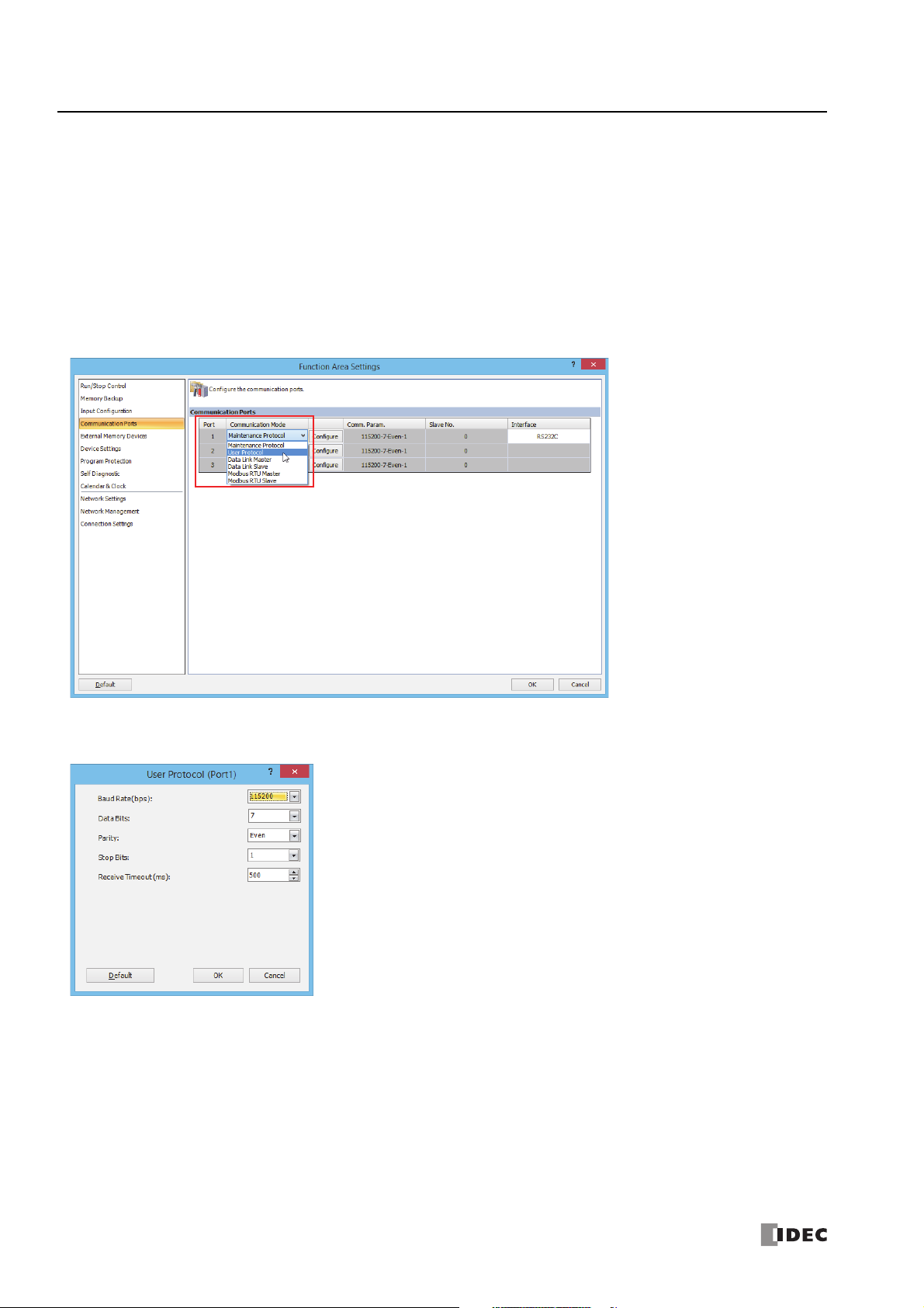
3: C
OMMUNICATION SETTINGS
Communication Port Settings
This section describes how to configure the communication ports when using serial port 1 (port 1) or a communication cartridge
(port 2 or port 3) connected to cartridge slot 1 or cartridge slot 2 to communicate with the communication device.
Programming WindLDR
Configure the communication format according to the communication specifications of the device.
1. From the WindLDR menu bar, select Configuration > Communication Ports.
The Function Area Settings dialog box is displayed.
2. Click Communication Mode for the port to use and select the communication mode to use.
The configuration dialog that corresponds to the communication mode is displayed.
3. Change the settings on the configuration dialog according to the communication format for the destination device.
A user communication example is shown below.
4. Click OK.
This concludes configuring the settings.
3-2 FC6A S
ERIES MICROSMART ALL-IN-ONE TYPE COMMUNICATION MANUAL
FC9Y-B1730

3: C
OMMUNICATION SETTINGS
Network Settings
This section describes the settings for using Ethernet port 1 or the HMI-Ethernet port to connect the FC6A Series MicroSmart to a
network.
Description
In order for the FC6A Series MicroSmart to connect to an Ethernet network, the FC6A Series MicroSmart network settings (FC6A
Series MicroSmart IP address, subnet mask, default gateway, and DNS server addresses) must be acquired or configured
according to the specification method.
IP Settings
The specification method for the FC6A Series MicroSmart IP address, subnet mask, and default gateway can be selected as the
following three types.
Specification Method Description
The FC6A Series MicroSmart will automatically acquire the IP address, subnet mask, and default gateway from
Obtain an IP Address
Automatically (DHCP)
Use Special Data Register
to Configure the
IP Address
Use the Following
IP Address
the DHCP server when the user program download has finished and when the FC6A Series MicroSmart power
is turned on. However, a DHCP server must be present on the network where the FC6A Series MicroSmart is
located.
Specify the IP address, subnet mask, and default gateway in special data registers D8304 to D8315. These
values are set on the FC6A Series MicroSmart when the FC6A Series MicroSmart power is turned on and when
special internal relay M8190 (CPU module network settings changed trigger) is turned on.
Specify a fixed IP address, subnet mask, and default gateway. The values specified here are reflected in the
FC6A Series MicroSmart when the user program download has finished.
Notes:
• The default FC6A Series MicroSmart settings are: IP address 192.168.1.5, subnet mask 255.255.255.0, default gateway 0.0.0.0.
• The FC6A Series MicroSmart IP address, subnet mask, and default gateway can be changed using the HMI module. For details, see Chapter
7 "HMI Function" in the "FC6A Series MicroSmart All-in-One Type User’s Manual".
DNS Settings
The specification method for the DNS server addresses can be selected as the following three types.
Specification Method Description
Obtain DNS Server
Address Automatically
(DHCP)
Use Special Data Registers
to Configure the DNS
Server Addresses
Use the Following DNS
Server Addresses
Notes:
• When an IP address cannot be obtained from the preferred DNS server, the alternate DNS server is accessed.
• The DNS server addresses can be changed using the HMI module. For details, see Chapter 7 "HMI Function" in the "FC6A Series MicroSmart
All-in-One Type User’s Manual".
The FC6A Series MicroSmart will automatically acquire the DNS server addresses from the DHCP server when
the user program download has finished and when the FC6A Series MicroSmart power is turned on. However,
a DHCP server must be present on the network where the FC6A Series MicroSmart is located.
Specify the preferred DNS server address and the alternate DNS server address in special data registers
D8316 to D8323. These values are set on the FC6A Series MicroSmart when the FC6A Series MicroSmart
power is turned on and when special internal relay M8190 (CPU module network settings changed trigger) is
turned on.
Specify a fixed preferred DNS server address and alternate DNS server address. The values specified here are
reflected in the FC6A Series MicroSmart when the user program download has finished.
FC6A S
ERIES MICROSMART ALL-IN-ONE TYPE COMMUNICATION MANUAL
FC9Y-B1730 3-3

3: C
OMMUNICATION SETTINGS
Network settings by special data registers
When IP Settings is set to "Use special data registers to configure the IP address" and DNS Settings is set to "Use special data
registers to configure the DNS server addresses" in the function area settings, the values that are set on the FC6A Series
MicroSmart when the FC6A Series MicroSmart power is turned on and when special internal relay M8190 (CPU module network
settings changed trigger) is turned on are stored in the following special data registers.
Special Data Register Description Read/Write
The FC6A Series MicroSmart IP address setting value.
D8304-D8307
D8308-D8311
D8312-D8315
D8316-D8319
D8320-D8323
Example: When the IP address is 192.168.0.1
D8304=192, D8305=168, D8306=0, D8307=1
The FC6A Series MicroSmart subnet mask setting value.
Example: When the subnet mask is 255.255.255.0
D8308=255, D8309=255, D8310=255, D8311=0
The FC6A Series MicroSmart default gateway setting value.
Example: When the default gateway is 192.168.0.24
D8312=192, D8313=168, D8314=0, D8315=24
The setting value of the preferred DNS server address used by the FC6A Series MicroSmart.
Example: When the preferred DNS address is 192.168.0.100
D8316=192, D8317=168, D8318=0, D8319=100
The setting value of the alternate DNS server address used by the FC6A Series MicroSmart.
Example: When the alternate DNS address is 192.168.0.101
D8320=192, D8321=168, D8322=0, D8323=101
R/W
R/W
R/W
R/W
R/W
Checking the network settings
The current FC6A Series MicroSmart IP address, subnet mask, default gateway, and DNS server addresses can be checked with
special data registers.
Special Data Register Description Read/Write
The FC6A Series MicroSmart IP address current value.
D8330-D8333
D8334-D8337
D8338-D8341
D8342-D8345
D8346-D8349
Example: When the IP address is 192.168.0.1
D8330=192, D8331=168, D8332=0, D8333=1
The FC6A Series MicroSmart subnet mask current value.
Example: When the subnet mask is 255.255.255.0
D8334=255, D8335=255, D8336=255, D8337=0
The FC6A Series MicroSmart default gateway current value.
Example: When the default gateway is 192.168.0.24
D8338=192, D8339=168, D8340=0, D8341=24
The current value of the preferred DNS server address used by the FC6A Series MicroSmart.
Example: When the preferred DNS address is 192.168.0.100
D8342=192, D8343=168, D8344=0, D8345=100
The current value of the alternate DNS server address used by the FC6A Series MicroSmart.
Example: When the alternate DNS address is 192.168.0.101
D8346=192, D8347=168, D8348=0, D8349=101
R
R
R
R
R
3-4 FC6A S
ERIES MICROSMART ALL-IN-ONE TYPE COMMUNICATION MANUAL
FC9Y-B1730

3: C
OMMUNICATION SETTINGS
Network settings by HMI module special data registers
When IP Settings is set to "Use special data register to configure the IP address" and DNS Settings is set to "Use special data
registers to configure the DNS server addresses" in the function area settings, the values that are set on the HMI module when the
FC6A Series MicroSmart power is turned on and when special internal relay M8184 (HMI module network settings changed trigger)
is turned on are stored in the following special data registers.
Special Data Register Description Read/Write
The HMI module IP address setting value.
D8437-D8440
D8441-D8444
D8445-D8448
D8449-D8452
D8453-D8456
Example: When the IP address is 192.168.0.1
D8437=192, D8438=168, D8439=0, D8440=1
The HMI module subnet mask setting value.
Example: When the subnet mask is 255.255.255.0
D8441=255, D8442=255, D8443=255, D8444=0
The HMI module default gateway setting value.
Example: When the default gateway is 192.168.0.24
D8445=192, D8446=168, D8447=0, D8448=24
The setting value of the preferred DNS server address used by the HMI module.
Example: When the preferred DNS address is 192.168.0.100
D8449=192, D8450=168, D8451=0, D8452=100
The setting value of the alternate DNS server address used by the HMI module.
Example: When the alternate DNS address is 192.168.0.101
D8453=192, D8454=168, D8455=0, D8456=101
R/W
R/W
R/W
R/W
R/W
Checking the HMI module network settings
The current HMI module IP address, subnet mask, default gateway, and DNS server addresses can be checked with special data
registers.
Special Data Register Description Read/Write
The HMI module IP address current value.
D8388-D8391
D8392-D8395
D8396-D8399
D8400-D8403
D8404-D8407
Example: When the IP address is 192.168.0.1
D8388=192, D8389=168, D8390=0, D8391=1
The HMI module subnet mask current value.
Example: When the subnet mask is 255.255.255.0
D8392=255, D8393=255, D8394=255, D8395=0
The HMI module default gateway current value.
Example: When the default gateway is 192.168.0.24
D8396=192, D8397=168, D8398=0, D8399=24
The current value of the preferred DNS server address used by the HMI module.
Example: When the preferred DNS address is 192.168.0.100
D8400=192, D8401=168, D8402=0, D8403=100
The current value of the alternate DNS server address used by the HMI module.
Example: When the alternate DNS address is 192.168.0.101
D8404=192, D8405=168, D8406=0, D8407=101
R
R
R
R
R
FC6A S
ERIES MICROSMART ALL-IN-ONE TYPE COMMUNICATION MANUAL
FC9Y-B1730 3-5

3: C
OMMUNICATION SETTINGS
Programming WindLDR
1. Select Configuration from the WindLDR menu bar, and then click Network Settings.
The Function Area Settings dialog box appears.
2. Configure IP Settings and DNS Settings.
3. Click OK.
4. Use the Module Configuration Editor to configure the HMI module network settings.
On the Configuration tab, in the PLCs group, select Expansion Modules.
5. Click the inserted HMI module in the module configuration area and click Configure.
The HMI Module Configuration dialog box is displayed.
Note: You can also display the HMI Module Configuration dialog box by double-clicking HMI Module in the Project Window.
3-6 FC6A S
ERIES MICROSMART ALL-IN-ONE TYPE COMMUNICATION MANUAL
FC9Y-B1730
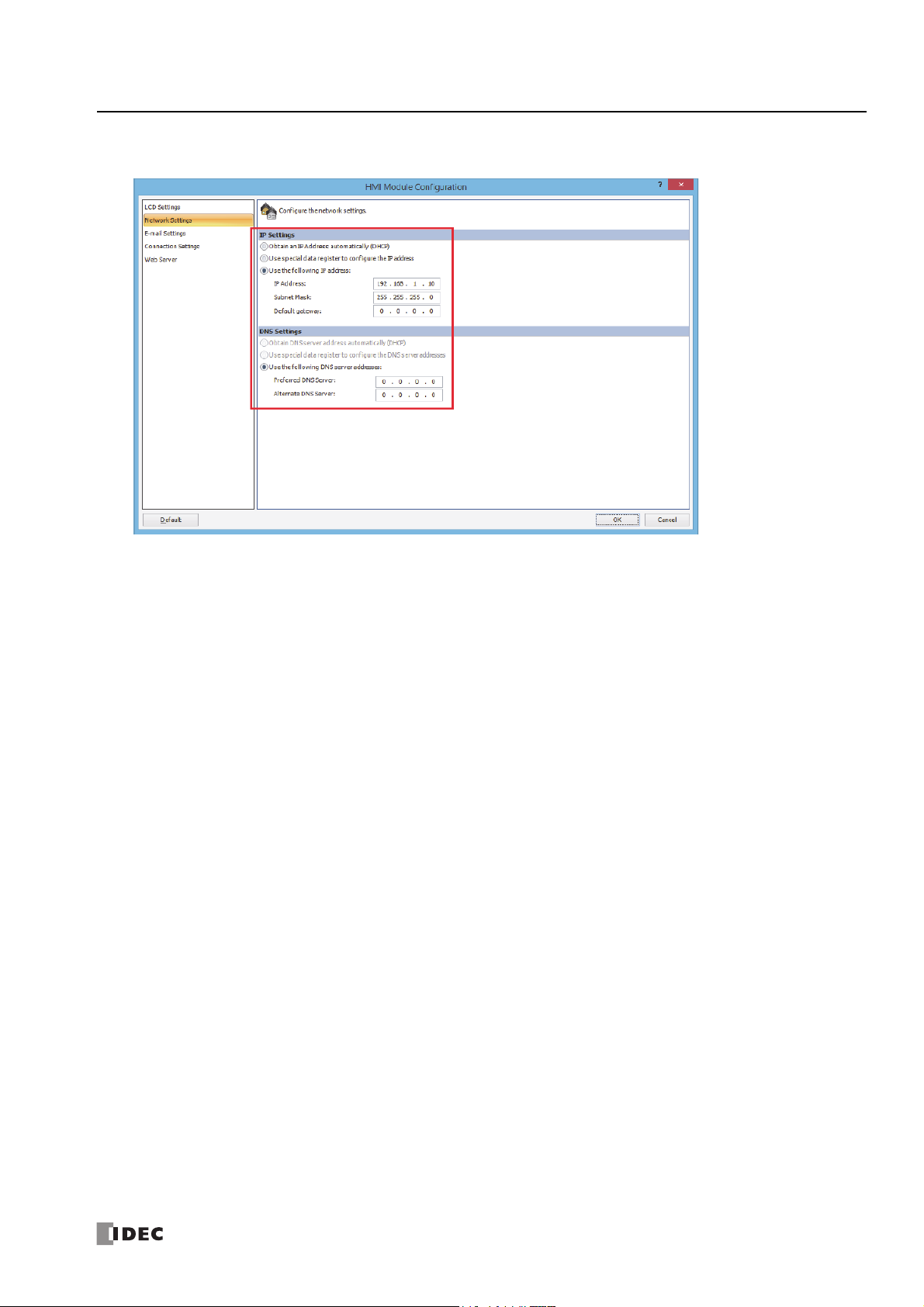
3: C
6. Click the Network Settings tab, and then configure the IP Settings and DNS Settings.
OMMUNICATION SETTINGS
This concludes configuring the settings.
FC6A S
ERIES MICROSMART ALL-IN-ONE TYPE COMMUNICATION MANUAL
FC9Y-B1730 3-7

3: C
OMMUNICATION SETTINGS
Network Management
SNTP Settings
This section describes the settings to adjust the clock in the FC6A Series MicroSmart by acquiring the current time (GMT) from an
SNTP server on the network.
Description
The FC6A Series MicroSmart acquires the current time (GMT) from an SNTP server on the network automatically or at the set
interval and adjusts the internal clock according to the time zone setting. If the daylight savings time setting has been enabled, the
current time (GMT) acquired from the SNTP server is corrected for daylight savings time during the daylight savings time period.
The time zone can be adjusted and the operation status of the SNTP server can be checked using special data registers.
Programming WindLDR
Configure the SNTP server used to acquire the current time and the acquisition method of the current time.
1. On the WindLDR Configuration tab, in the Function Area Settings group, click Network Management.
The Function Area Settings dialog box is displayed.
2. Select the Acquire the current date and time from an SNTP server check box.
3. Configure the SNTP server, time zone, and acquisition method of the current time.
Item Setting Value
SNTP Server (IP Address)
SNTP Server (Host Name)
SNTP Server Port Specify the SNTP server port number (0 to 65535).
Time Zone
3-8 FC6A S
Specify the IP address of the SNTP server used to acquire the current time.
The format is "xxx.xxx.xxx.xxx". "xxx" stands for a numeric value from 0 to 255.
Specify the host name of the SNTP server used to acquire the current time.
The host name can be entered up to 40 single-byte alphanumeric characters.
Select the difference of the regional time zone in regard to the standard time acquired from the SNTP server.
The time zone can be selected in the range of GMT-12:00 to GMT+13:00.
The time zone can be adjusted in 15 minute increments using special data register D8413.
ERIES MICROSMART ALL-IN-ONE TYPE COMMUNICATION MANUAL
FC9Y-B1730

3: C
Bit
15
Bit
0
Bit
7
Bit
8
Lower 4 Bits
Error Code
Upper 12 Bits
Status Code
Bit 4Bit
3
OMMUNICATION SETTINGS
4. To automatically acquire the current time, select the Automatic Acquisition check box.
When a keep data error occurs and when the user program is downloaded and automatic acquisition is changed from off to on,
the current time is automatically acquired from the SNTP server.
To periodically acquire the current time at a timing other than the above, select the Cycle check box and select the cycle as
"Every 10 Minutes", "Every Hour", "Every Day", or "Every 30 Days".
To acquire the current time from the SNTP server when the FC6A Series MicroSmart power is turned on, select the
At PLC power on
check box.
When the Automatic Acquisition check box is cleared, if special internal relay M8191 is turned from off to on, the current
time is acquired from the SNTP server.
5. Click OK.
This concludes configuring the settings.
Adjusting the time zone (D8413)
The selected time zone (GMT-12:00 to GMT+13:00) can be adjusted in 15 minute increments with the value of special data
register D8413 (time zone offset).
For example, if GMT+09:00 is selected, storing +1 in D8413 advances the time by 15 minutes to make the time zone
"GMT+09:15". Storing -2 in D8413 sets the time back by -30 minutes to make the time zone "GMT+08:30".
Checking the operation status (D8414)
The SNTP Operation Status is stored in special data register D8414 (SNTP Operation Status). The operation status indicates the
operation status (status code) and the error details (error code).
The operation status (status code) is stored in the upper 12 bits of D8414 and the error details (error code) is stored in the lower
4 bits of D8414.
Status Code Operation Status Status Description
0 (000000000000) No operation When there is no access to the SNTP server
32 (000000100000) Waiting for response
64 (000001000000)
Error Code Error Details
0 (0000) Normal
2 (0010) Timeout error
3 (0011) The set SNTP server IP address could not be resolved by DNS
9 (1001) Invalid data was received
Time information acquisition
successful
When the SNTP server has been accessed and waiting for the response from
the SNTP server
When the response from the SNTP server was normally received
Acquire the current time at an arbitrary timing (M8191)
When special internal relay M8191 (SNTP time acquisition flag) is turned on, the current time is acquired from the SNTP server.
Elapsed time since acquiring the current time (D8415)
The elapsed time (0 to 65,535) in minutes since last acquiring the current time from the SNTP server is stored in special data
register D8415 (elapsed time since SNTP access). Since the values that can be stored are between 0 and 65,535, 65,535 minutes
/ 60 minutes / 24 hours = approximately 45 days, so the maximum value that can be measured is 45 days.
For example, when the date and time that the current time was last acquired from the SNTP server is January 1 at 12:00, if the
value of D8415 is checked on January 1 at 15:00, the value stored is "180" because 3 hours = 180 minutes have elapsed.
D8145 is reset to 0 when the current time is successfully acquired, then the elapsed time count starts. If acquiring the current time
from the SNTP server was not successful even once, the value of D8145 is not updated.
FC6A S
ERIES MICROSMART ALL-IN-ONE TYPE COMMUNICATION MANUAL
FC9Y-B1730 3-9

3: C
OMMUNICATION SETTINGS
Ping Settings
This section describes the ping timeout setting for the PING instruction and when the auto ping function is being executed.
Description
When sending pings with the PING instruction or auto ping function, a ping packet is sent to the specified remote host to check
whether or not communication is possible at the IP level. Set the time from when this ping is sent until the timeout occurs.
Programming WindLDR
1. On the Configuration tab, in the Function Area Settings group, click Network Management.
The Function Area Settings dialog box is displayed.
2. With Timeout (10 to 30000 msec), set the PING instruction timeout between 10 and 30,000 ms.
The default is 10 ms.
3. Click OK.
This concludes configuring the settings.
3-10 FC6A S
ERIES MICROSMART ALL-IN-ONE TYPE COMMUNICATION MANUAL
FC9Y-B1730

3: C
OMMUNICATION SETTINGS
Connection Settings
This section describes the settings for client/server communication during TCP/IP communication using Ethernet port 1 or the
HMI-Ethernet port of the FC6A Series MicroSmart.
Applications
The FC6A Series MicroSmart is capable of maintenance communication, user communication, and Modbus TCP communication
using a maximum of eight connections over Ethernet port 1.
Those communications can be configured in the Function Area Settings dialog box.
Also, the HMI-Ethernet port can be used to expand a maximum of eight connections when using an HMI module.
However, the only communication function that is supported by the HMI-Ethernet port is maintenance communication.
Description of functions
Each connection can be selected as maintenance communication server, user communication server, user communication client,
Modbus TCP server, Modbus TCP client, or unused, and a maximum of eight connections can be configured.
To limit the access to the FC6A Series MicroSmart, IP address flittering can be used. By specifying the IP address that can access
the FC6A Series MicroSmart, anonymous access can be prevented.
Communication Mode Overview
Maintenance
communication server
(Default)
User communication
server
User communication client
Modbus TCP server
Modbus TCP client
Unused The connection is not used. ―
This mode allows monitoring and changing devices and user program uploading and downloading
from WindLDR.
This mode enables communication with client devices according to the ETXD (Ethernet user
communication transmit) instruction and the ERXD (Ethernet user communication receive) instruction.
This mode enables communication with server devices according to the ETXD (Ethernet user
communication transmit) instruction and the ERXD (Ethernet user communication receive) instruction.
When the FC6A Series MicroSmart is configured as a Modbus TCP server, FC6A Series MicroSmart data
monitoring and modifications can be executed from Modbus TCP client-compatible devices.
Modbus TCP server-compatible device data monitoring and modifications can be executed from
Modbus TCP clients.
Reference
4-6
5-40
5-37
6-24
6-19
Connection Status and Connected IP Address
The connection status of connections with remote hosts can be confirmed with special internal relays M8212 to M8221. When a
connection with a remote host is established, the corresponding special internal relay is turned on. When the connection is
disconnected, the corresponding special internal relay is turned off. The IP addresses of the remote hosts can be confirmed with
special data registers D8350 to D8381.
Note: R/W is the abbreviation for read/write. When R/W, it can be read and written. When R, it can only be read. When W, it can only be written.
Special Internal Relays
Device Address Description Details Read/Write
M8212 Connection 1 Status
M8213 Connection 2 Status
M8214 Connection 3 Status
M8215 Connection 4 Status
M8216 Connection 5 Status
M8217 Connection 6 Status
M8220 Connection 7 Status
M8221 Connection 8 Status
M8222 Connection 1 disconnected flag
M8223 Connection 2 disconnected flag
M8224 Connection 3 disconnected flag
M8225 Connection 4 disconnected flag
M8226 Connection 5 disconnected flag
M8227 Connection 6 disconnected flag
M8230 Connection 7 disconnected flag
M8231 Connection 8 disconnected flag
While a connection is established with a remote host, the
special internal relay will be on. When no connection is
established, it will be off.
When turned on, the connection to the server is forcibly
disconnected to stop communication. When turned off,
the connection to the server is established and
communication is restarted.
This flag is only valid in user communication client and
Modbus TCP client.
R
R/W
FC6A S
ERIES MICROSMART ALL-IN-ONE TYPE COMMUNICATION MANUAL
FC9Y-B1730 3-11

3: C
OMMUNICATION SETTINGS
Connected IP addresses
Special Data Register Description Read/Write
D8350-D8353 Connection 1 Connected IP Address
D8354-D8357 Connection 2 Connected IP Address
D8358-D8361 Connection 3 Connected IP Address
D8362-D8365 Connection 4 Connected IP Address
D8366-D8369 Connection 5 Connected IP Address
D8370-D8373 Connection 6 Connected IP Address
D8374-D8377 Connection 7 Connected IP Address
D8378-D8381 Connection 8 Connected IP Address
When communication has been established between an
external device and a connection, the IP address of the
connected external device is stored in special data
registers as shown below.
Example: IP Address: aaa.bbb.ccc.ddd,
D8350=aaa, D8351=bbb, D8352=ccc, D8353=ddd
HMI module connection status information and connected IP address
The connection status for the HMI module connection number specified by D8429 is stored in special internal relays and special
data registers.
The status of the connection to an HMI module external device can be checked with special internal relay M8232.
The relay is on when connected to the external device and off when not connected.
The connected IP address can be checked with special data registers D8430 to D8433.
Read specified target connection number
Special Internal Relays Description Read/Write
Reflects the connection information for the specified number
D8429
HMI module
read target connection
number
to D8430 through D8434 and M8232.
When 0 is specified, the target devices are all set to 0.
If a connection not that does not exist is specified, the
operation is the same as when 0 is specified.
R/W
R
Status information
Special Internal Relays Description Read/Write
M8232
HMI module
connection status
On when the connection specified with D8429 is connected to
an external device and off when there is no connection.
R
Connected IP Address
Special Internal Relays Description Read/Write
When communication has been established between an
external device and the connection specified by D8429, the IP
D8430-D8433
HMI connection
Connected IP Address
address of the connected external device is stored in special
data registers as shown below.
Example: IP Address: aaa.bbb.ccc.ddd,
D8350=aaa, D8351=bbb, D8352=ccc, D8353=ddd
R
3-12 FC6A S
ERIES MICROSMART ALL-IN-ONE TYPE COMMUNICATION MANUAL
FC9Y-B1730

3: C
OMMUNICATION SETTINGS
Programming WindLDR
1. From the WindLDR menu bar, select Configuration > Connection Settings.
The Function Area Settings dialog box is displayed.
2. Click Communication Mode for the port to be used and select communication mode of the connection to use.
Configure the communication mode allocated to a maximum of eight connections that can be used as client or server. Each
connection can be set to a different port number. Set connections that are not used to Unused.
A dialog box is displayed according to the communication mode.
3. Specify the parameters according to the communication format of the destination device.
4. Click OK.
5. Use the Module Configuration Editor to configure the HMI module network settings.
On the Configuration tab, in the PLCs group, select Expansion Modules.
FC6A S
ERIES MICROSMART ALL-IN-ONE TYPE COMMUNICATION MANUAL
FC9Y-B1730 3-13

3: C
OMMUNICATION SETTINGS
6. Click the inserted HMI module in the module configuration area and click Configure.
The HMI Module Configuration dialog box is displayed.
Note: You can also display the HMI Module Configuration dialog box by double-clicking HMI Module in the Project Window.
7. Click Connection Settings.
8. Click Communication Mode for the port to be used and select communication mode of the connection to use.
3-14 FC6A S
ERIES MICROSMART ALL-IN-ONE TYPE COMMUNICATION MANUAL
FC9Y-B1730

9. Specify the parameters according to the communication format of the destination device.
10. Click OK.
This concludes configuring the settings.
3: C
OMMUNICATION SETTINGS
FC6A S
ERIES MICROSMART ALL-IN-ONE TYPE COMMUNICATION MANUAL
FC9Y-B1730 3-15

3: C
OMMUNICATION SETTINGS
Remote Host List
This chapter describes how to configure a list of network devices (remote hosts) in the network to which the FC6A Series
MicroSmart communicates.
Description
When the FC6A Series MicroSmart accesses and communicates with other network devices in the network, the remote host device
should be specified. The remote host list is required to use the following functions:
• PING Instruction
• ETXD/ERXD Instructions (User communication over Ethernet)
• Modbus TCP Client
Description of Functions
The remote host consists of an IP Address or a Host Name and a Port Number.
When a remote host is specified with an IP address, and the FC6A Series MicroSmart establishes connection with the remote host
that has the specified IP address and the corresponding port number, then communication is started.
When a remote host is specified with a host name, the FC6A Series MicroSmart tries to obtain the IP address from the specified
host name using the DNS server. If the IP address is successfully obtained, the FC6A Series MicroSmart establishes connection
with the remote host that has the specified IP address and the corresponding port number, then communication is started.
For details about DNS server settings, see Network Settings in the Function Area Settings.
Programming WindLDR
1. Click Project Window in the Work Space on the View tab.
The Project Window is displayed on the left side of the screen.
2. Double-click on the Remote Host List in the Project Window.
The Remote Host List dialog box appears.
3. Click New button.
The Remote Host List dialog box appears.
3-16 FC6A S
ERIES MICROSMART ALL-IN-ONE TYPE COMMUNICATION MANUAL
FC9Y-B1730

3: C
OMMUNICATION SETTINGS
4. Configure the parameters in the Remote Host dialog box and then click on Add button.
The remote host is composed of the following items.
Item
Setting Value
IP Address Specify the remote host with an IP address. The FC6A Series MicroSmart will communicate by establishing a
connection to the set IP address and port number.
Host Name Specifies the remote host as a host name. Up to 40 single-byte alphanumeric characters can be entered.
Data Register Specify the IP address of the remote host as data registers (4 words).
Port Number Specify the port number of the remote host. This port number is the TCP communication port number. It
differs from the numbers of the FC6A Series MicroSmart USB port and port 1 through port 3.
Comment The comment for the remote host can be assigned. The contents or the lngth of the comment has no effect
on the FC6A Series MicroSmart operation.
A new remote host will be added in the Remote Host List dialog box. If you want to add additional remote hosts, repeat the
same procedure.
5. To periodically ping the specified remote host, configure auto ping.
For details, see "Auto Ping Function" on page 3-18.
6. After adding remote hosts has been completed, click on Close button.
7. If you want to delete an unused remote host, select that remote host in the Remote Host List dialog box and click on Delete
button.
This concludes configuring the settings.
Note: Once a remote host is deleted, the remote host numbers of the following remote hosts are changed. As a result, there is an effect on the
operation of the PING instruction, Modbus TCP client, and user communication client that refer to these remote host list numbers.
FC6A S
ERIES MICROSMART ALL-IN-ONE TYPE COMMUNICATION MANUAL
FC9Y-B1730 3-17

3: C
OMMUNICATION SETTINGS
Auto Ping Function
This section describes the auto ping function that periodically pings the specified remote host.
Function Description
The function to periodically ping the specified remote host is called the auto ping function. This function can be used to check
whether or not communication is possible with the specified remote host by sending a packet to that host.
The remote host is specified with the remote host list.
When auto ping is enabled and immediately after auto ping is enabled due to the FC6A Series MicroSmart power being turned on
and a change in the user program, auto ping execution starts and the specified remote host numbers are pinged in order from the
smallest number. There is no impact on the FC6A run and stop statuses and the ladder program. Auto ping is stopped while M8187
(auto ping stop flag) is on. When M8187 is turned off, auto ping execution starts.
The results of the auto ping function can be linked with Modbus TCP client request processing. For linking with Modbus TCP clients,
see "Modbus TCP Client" on page 6-19.
Programming WindLDR
1. In the Remote Host List dialog box, select the Auto Ping check box and click Configure.
The Auto Ping Settings dialog box is displayed.
3-18 FC6A S
ERIES MICROSMART ALL-IN-ONE TYPE COMMUNICATION MANUAL
FC9Y-B1730

3: C
OMMUNICATION SETTINGS
2. Specify the auto ping function items and click OK.
The auto ping function is composed of the following items.
Item Setting Value
Specify the internal relay that stores the results of the pings sent with the auto ping function. If an internal relay is
entered, the range of internal relays that will be used is displayed on the right side.
The internal relays are all turned off when auto ping function execution starts. After the ping is sent, they are
Online Status:
Operation Status:
Retry: Specify the retry count (0 to 5 times) of the ping sent with the auto ping function.
Ping Interval: Specify the send interval (0 to 60,000 ms) of the pings sent with the auto ping function in 10 ms increments.
Auto Ping Interval:
turned on when a response is received.
When M8187 (auto ping stop flag) is turned from off to on, or when the user program is changed and the auto ping
function is set from "Used" to "Not used", the internal relay on/off status immediately before that is kept.
When M8187 (auto ping stop flag) is turned from on to off, or when the user program is changed and the auto
ping function is set from "Not used" to "Used", the internal relays are all turned off.
There is no impact on the operation of the PING instruction.
Specify the data register that stores the operation status of the ping sent with the auto ping function. If a data
register is entered, the range of data registers that will be used is displayed on the right side.
The operation status indicates the operation status (status code) and the error details (error code). The status
code is stored in the upper 12 bits and the error code is stored in the lower 4 bits.
For the status code details, see "Operation status" on page 3-20.
There is no impact on the operation of the PING instruction.
Specify the interval (100 to 6,000,000 ms) until the next auto ping is executed after the auto ping was executed in
100 ms increments.
3. In the Remote Host List dialog box, select the check box of the remote hosts to ping when auto ping executes.
4. Click Close.
This concludes configuring the settings.
FC6A S
ERIES MICROSMART ALL-IN-ONE TYPE COMMUNICATION MANUAL
FC9Y-B1730 3-19

3: C
Bit
15
Bit
0
Bit
7
Bit
8
Lower 4 Bits
Error Code
Upper 12 Bits
Status Code
Bit 4Bit
3
M0000
ON
OFF
M0001
ON
OFF
M0002
ON
OFF
(1) (4) (6)
(2)
(3) (7) (8) (9)
(10)
(5)
FC6A
Host 1
Host 2
Host 3
500 ms
1,000 ms
1,000 ms 1,000 ms 60,000 ms 1,000 ms
OMMUNICATION SETTINGS
Operation status
The operation status indicates the operation status (status code) and the error details (error code).
The operation status (status code) is stored in the upper 12 bits of D8414 and the error details (error code) is stored in the lower
4 bits of D8414.
Status Code Operation Status
16 (000000010000) Status after ping executed and before the packet is sent
32 (000000100000) Status after packet send processing has completed and waiting for a response from the host
64 (000001000000)
Error Code Error Details
0 (0000) Normal
2 (0010) Timeout error
3 (0011) The destination host name could not be resolved by DNS
Status where receiving the response for the packet completed normally or a timeout error occurred and the next
ping can be executed
Auto ping operation example 1
This example describes the operation when auto ping is executed for three remote hosts under the following conditions.
Settings Setting Details
Ping settings Timeout 1,000 ms
Online Status M0000
Auto ping settings
Retry 0 times
Ping Interval 1,000 ms
Auto Ping Interval 60,000 ms
(1) : Auto ping operation starts
(2) to (3) : Response from Host 1 within the timeout
(4) : No response from Host 2 within the timeout
(5) to (6) : Response from Host 3 within the timeout
(7) to (8) : Auto Ping Interval
(8) : No response from Host 1 within the timeout
(9) to (10) : Response from Host 2 within the timeout
3-20 FC6A S
ERIES MICROSMART ALL-IN-ONE TYPE COMMUNICATION MANUAL
FC9Y-B1730

3: C
M0000
ON
OFF
M0001
ON
OFF
M0002
ON
OFF
(1) (5) (7)(3)
(2)
(4) (8)(6)
FC6A
Host 1
Host 2
Host 3
200 ms
500 ms
2,000 ms 2,000 ms 600 ms 30,000 ms
OMMUNICATION SETTINGS
Auto ping operation example 2
This example describes the operation when auto ping is executed for three remote hosts under the following conditions.
Settings Setting Details
Ping settings Timeout 2,000 ms
Online Status M0000
Auto ping settings
Retry 1 time
Ping Interval 500 ms
Auto Ping Interval 30,000 ms
(1) : Auto ping operation starts
(2) to (3) : Response from Host 1 within the timeout
(4) to (5) : No response from Host 2 within the timeout, no response even for retries
When the timeout is longer than the ping interval, there is no ping interval wait time.
(6) : Response from Host 3 was late, but within the timeout
(7) to (8) : Auto Ping Interval
FC6A S
ERIES MICROSMART ALL-IN-ONE TYPE COMMUNICATION MANUAL
FC9Y-B1730 3-21

3: C
OMMUNICATION SETTINGS
3-22 FC6A S
ERIES MICROSMART ALL-IN-ONE TYPE COMMUNICATION MANUAL
FC9Y-B1730

4: M
AINTENANCE
C
OMMUNICATION
Introduction
This chapter describes the FC6A Series MicroSmart maintenance communication function.
Maintenance communication is a communication protocol dedicated for IDEC programmable controllers. It is used when WindLDR
or an IDEC operator interface communicates with the FC6A Series MicroSmart.
Maintenance communication of FC6A Series MicroSmart is available on USB port, port1, Ethernet port1, port 2 and port 3, and
HMI-Ethernet port, allowing the optimum communication method to be selected for a variety of system configurations.
Maintenance Communication Functions
When performing maintenance communication with the FC6A Series MicroSmart, the following functions can be used:
Function Description
Download user programs
Upload user programs User programs stored in the FC6A Series MicroSmart can be uploaded to WindLDR.
Monitor/change device values
Download system software
Note: To use maintenance communication, see Chapter 4 "Start WindLDR" in the "FC6A Series MicroSmart All-in-One Type User’s Manual" and
perform setup.
User programs created in WindLDR can be downloaded to the FC6A Series MicroSmart.
See Chapter 4 "Download Program" in the "FC6A Series MicroSmart All-in-One Type User’s Manual".
The user program and the device values of the FC6A Series MicroSmart can be monitored and the device
values can be changed using WindLDR.
See Chapter 4 "Monitor Operation" in the "FC6A Series MicroSmart All-in-One Type User’s Manual".
System software can be downloaded to the FC6A Series MicroSmart.
See Appendix "Upgrade FC6A Series MicroSmart System Software" in the "FC6A Series MicroSmart All-in-One
Type User’s M a nu a l".
Communication Ports Used For Maintenance Communication
Supported models, ports, and slots are as follows.
Port
USB PortYesYesYesYes
Port 1 Yes Yes Yes ―
Ethernet Port 1 Yes Yes Yes Yes
Port 2 Yes Yes Yes Yes
Port 3 ――Yes Yes
HMI-Ethernet Port Yes Yes Yes Yes
Maintenance communication methods that are supported by the communication ports are as follows.
Communication Method USB Port Port 1
Maintenance Communication
16-I/O Type 24-I/O Type 40-I/O Type
Downloading system
software
Download/upload user
programs
Run-t ime dow nlo ad Ye s Yes Yes N o Yes
Monitoring/changing
devices
All-in-One Type
Ethernet
Port 1
Yes Yes Yes N o Ye s
Yes Ye s Yes No Yes
Yes Ye s Yes Ye s Yes
CAN J1939 All-in-One
Type
Port 2 and
Port 3
HMI-Ethernet
Port
FC6A S
ERIES MICROSMART ALL-IN-ONE TYPE COMMUNICATION MANUAL
FC9Y-B1730 4-1

4: M
AINTENANCE COMMUNICATION
Maintenance communication functions that are supported by the communication ports and slots are as follows.
Communication
Port
USB Port Standard 1 None
Port 1
Ethernet Port 1 Standard 1
Port 2 and Port 3
HMI-Ethernet Port
All-in-One Type: Standard equipment
CAN J1939 All-in-One Type: ―
Options
FC6A-PC1: EIA RS-232C (terminal block)
FC6A-PC3: EIA RS-485 (terminal block)
Options
FC6A-PH1 (HMI module)
Standard/Option No. of Ports Communication Settings
Function area settings
1
16-I/O type: 1
24-I/O type: 1
40-I/O type: 2
1
See "Maintenance Communication via Port 1"
on page 4-4.
Function area settings
See "Maintenance Communication via Ethernet
Port 1" on page 4-6.
Function area settings
See "Maintenance Communication via a
Communication Cartridge (Port 2, Port 3)" on
page 4-11.
Function area settings
See "Maintenance Communication via HMIEthernet port" on page 4-13
4-2 FC6A S
ERIES MICROSMART ALL-IN-ONE TYPE COMMUNICATION MANUAL
FC9Y-B1730

4: M
FC6A Series MicroSmart
USB Port
(USB 2.0 Mini-B Connector)
Computer
USB Port
Type A Plug
USB Cable
HG9Z-XCM42 USB Maintenance Cable
Mini-B Plug
AINTENANCE COMMUNICATION
Maintenance Communication via USB Port
Using the USB port, it is possible to connect FC6A Series MicroSmart to a computer on which WindLDR is installed, and monitor
and change device values, download and upload user programs, and download system software. Connect the computer and the
FC6A Series MicroSmart using a USB cable (recommended cable: HG9Z-XCM42).
Maintenance Communication Specifications for the USB Port
Item Specifications/Functions
Cable Recommended cable: HG9Z-XCM42
Monitor/change device values
Maintenance communication
functions
For details on the operation of maintenance communication functions, see the following in the "FC6A Series MicroSmart All-in-One
Type User’s Manual".
• Monitor/change device values: Chapter 4 "Monitor Operation"
• Download/upload user programs: Chapter 4 "Download Program"
• Download system software: Appendix "Upgrade FC6A Series MicroSmart System Software"
Download/upload user programs
Download system software
Run-time download
FC6A S
ERIES MICROSMART ALL-IN-ONE TYPE COMMUNICATION MANUAL
FC9Y-B1730 4-3

4: M
Serial Port 1
(Port 1)
Computer
Serial Communication Port
(RS232C)
Connection Cable
FC6A Series MicroSmart
AINTENANCE COMMUNICATION
Maintenance Communication via Port 1
Using Serial Port 1 on the FC6A Series MicroSmart, it is possible to connect to a computer on which WindLDR is installed or an
operator interface, and monitor and change device values, download and upload user programs, and download system software.
For details on communication cables, see Appendix "Cables" in the "FC6A Series MicroSmart All-in-One Type User’s Manual".
Port 1 maintenance communication specification
Item Specifications/Functions
Cable FC6A-KC2C: O/I communication cable (D-sub 9-pin connector style, cable length: 5 m)
Monitoring/changing device values
Maintenance communication
functions
For details on the operation of maintenance communication functions, see the following in the "FC6A Series MicroSmart All-in-One
Type User’s Manual".
• Monitor/change device values: Chapter 4 "Monitor Operation"
• Downloading/uploading user programs: Chapter 4 "Download Program"
• Downloading system software: Appendix "Upgrade FC6A Series MicroSmart System Software"
Downloading/uploading user programs
Downloading system software
Run-time download
Programming WindLDR
Configure the settings for maintenance communication.
1. From the WindLDR menu bar, select Configuration > Comm. Ports.
The Function Area Settings dialog box appears.
4-4 FC6A S
ERIES MICROSMART ALL-IN-ONE TYPE COMMUNICATION MANUAL
FC9Y-B1730

4: M
AINTENANCE COMMUNICATION
2. Click Communication Mode for port 1 and select Maintenance Protocol.
The Maintenance Protocol (Port1) dialog box appears.
3. Configure the parameters to match the communication settings of the computer or operator interface.
Baud Rate (bps): 115200 bps (1200, 2400, 4800, 9600, 19200, 38400, 57600, 115200)
Data Bits: 7 (7 or 8)
Parity: Even (None, Even, Odd)
Stop Bits: 1 (1 or 2)
Receive Timeout (ms): 500 (10 to 2550)
Slave Number: 0 (0 to 31)
Slave number can be specified by either a constant or a data register.
Type Details
Constant Set within the range of 0 to 31
Store the slave numbers 0 to 31 in the following special data registers
Data register
Port 1: D8100
Port 2: D8102
Port 3: D8103
* Values not in parentheses are the default settings.
* Set Data Bits to 8 when downloading the system software over port 1.
4. Click OK.
Configuring the maintenance communication for the expansion communication port is now complete.
FC6A S
ERIES MICROSMART ALL-IN-ONE TYPE COMMUNICATION MANUAL
FC9Y-B1730 4-5

4: M
AINTENANCE COMMUNICATION
Maintenance Communication via Ethernet Port 1
Network devices such as computers or IDEC operator interfaces can communicate with FC6A Series MicroSmart via Ethernet port
1. External devices on the network can monitor or change the device values and download or upload user programs.
It is possible to use the maintenance communication server and other communications simultaneously by assigning a separate
communication function such as a maintenance communication server or Modbus TCP communication to each of the three
connections on the FC6A Series MicroSmart.
Computer
Ethernet
FC6A Series MicroSmart
Maintenance
Communication Server
Computer Operator Interface
WindLDRWindLDR
Connection 2
Connection 1
Ethernet Port 1
Connection 3
Maintenance Communication Specifications for the Ethernet Port 1
Item Specifications/Functions
Cable LAN cable (Cat 5. STP)
Monitor/change device values
Maintenance communication
functions
For details on the operation of maintenance communication functions, see the following in the "FC6A Series MicroSmart All-in-One
Type User’s Manual".
• Monitor/change device values: Chapter 4 "Monitor Operation"
• Download/upload user programs: Chapter 4 "Download Program"
• Downloading system software: Appendix "Upgrade FC6A Series MicroSmart System Software"
Download/upload user programs
Downloading system software
Run-time download
4-6 FC6A S
ERIES MICROSMART ALL-IN-ONE TYPE COMMUNICATION MANUAL
FC9Y-B1730

4: M
AINTENANCE COMMUNICATION
Programming WindLDR
This section describes the procedures to configure the maintenance communication server for the Ethernet port 1 and
communicate with the FC6A Series MicroSmart via Ethernet.
Configure Maintenance Communication Server
1. From the WindLDR menu bar, select Configuration > Network Settings.
The Function Area Settings dialog box appears.
2. Enter the IP address, subnet mask, and default gateway.
3. Click Connection Settings.
4. Click Communication Mode for the connection that will be used and select Maintenance Communication Server.
The Maintenance Communication Server dialog box appears.
FC6A S
ERIES MICROSMART ALL-IN-ONE TYPE COMMUNICATION MANUAL
FC9Y-B1730 4-7

4: M
AINTENANCE COMMUNICATION
5. Set the parameters to match the communication settings of the PC or operator interface.
Local Host Port No.: 2101 (The port number that the FC6A Series MicroSmart uses for the maintenance communication server)
Receive Timeout (ms): 2000 (100 to 25500)
Allow Access by IP Address: Disabled (Enabling this option makes it possible to prevent access from devices having any IP addresses other
than the one entered.)
Enable Pass-Through over Modbus RTU (Port1):
Port 1 can be used as the pass-through port. In this case, set Communication Mode for port 1
to Modbus RTU Master. Specify a port number different from the port numbers of the other
server connections as the local host port number of the connection used for the pass-through.
Note: The number of clients that can be connected to the FC6A Series MicroSmart simultaneously is one client per connection. If connections 1 to
8 are all set to the maintenance communication server, eight clients can connect to the FC6A Series MicroSmart at the same time.
6. Click OK.
This completes maintenance communications settings.
Download User Program and Confirm IP Addresses via USB Port
Before starting Ethernet communication, configure the function area settings and download the user program to the FC6A Series
MicroSmart via USB.
7. Connect the PC and the FC6A Series MicroSmart using a USB cable.
8. From the WindLDR menu bar, select Online > Transfer > Download.
The Download dialog box appears.
9. Click OK.
The user program is downloaded to the FC6A Series MicroSmart.
10. After the user program has been successfully downloaded, go to Monitor Mode to check the status of the FC6A Series
MicroSmart. Select Online > Monitor > Monitor from the WindLDR menu bar.
4-8 FC6A S
ERIES MICROSMART ALL-IN-ONE TYPE COMMUNICATION MANUAL
FC9Y-B1730

4: M
11. From the WindLDR menu bar, select Online > Monitor > Batch.
The Batch Monitor dialog box appears.
12. Confirm that the IP address entered in step 2 is correctly shown in D8330 to D8333.
This concludes downloading the user program via the USB port and checking the IP address.
Monitor FC6A Series MicroSmart via the Ethernet Port 1
Monitor the FC6A Series MicroSmart via Ethernet using WindLDR.
13. From the WindLDR menu bar, select Online > Communication > Set Up.
The Communication Settings dialog box appears.
AINTENANCE COMMUNICATION
14. Select the Ethernet tab and click Browse.
The IP Address Settings dialog box appears.
15. Click New.
The Input IP address dialog box appears.
FC6A S
ERIES MICROSMART ALL-IN-ONE TYPE COMMUNICATION MANUAL
FC9Y-B1730 4-9

4: M
AINTENANCE COMMUNICATION
16. Enter the IP address entered in step 2 and click OK.
17. From the WindLDR menu bar, select Online > Monitor > Monitor.
The IP Address Settings dialog box appears.
18. Select the IP address you entered and click OK.
19. From the WindLDR menu bar, select Online > PLC > Status.
The PLC Status dialog box appears.
20. Check that the FC6A Series MicroSmart module type and system software version are displayed correctly.
Configuring the initial Ethernet setup for the maintenance communication server is now complete. You can download and upload
user programs and monitor and change device values via Ethernet.
4-10 FC6A S
ERIES MICROSMART ALL-IN-ONE TYPE COMMUNICATION MANUAL
FC9Y-B1730

4: M
Operator Interface
FC6A Series MicroSmart
Communication Cartridge
AINTENANCE COMMUNICATION
Maintenance Communication via a Communication Cartridge (Port 2, Port 3)
By attaching a communication cartridge to a cartridge slot on the FC6A Series MicroSmart, it is possible to connect to a computer
or an operator interface with a RS-232C or RS-485 port and to monitor and change device values.
For the communication cable, see Appendix "Upgrade FC6A Series MicroSmart System Software" in the "FC6A Series MicroSmart
All-in-One Type User’s Manual".
Communication cartridge maintenance communication specifications
Item Specifications/Functions
Communication Cartridge
Cable
Maintenance Communication
Function
FC6A-PC1: RS232C communication cartridge
FC6A-PC3: RS485 communication cartridge
FC6A-PC1: RS232C: Shielded multicore
FC6A-PC3: Shielded twisted-pair
Monitoring/changing device values
For details on the operation of maintenance communication functions, see the following in the "FC6A Series MicroSmart All-in-One
Type User’s Manual".
• Monitoring/changing device values: Chapter 4 "Monitor Operation"
Programming WindLDR
Configure the settings for maintenance communication.
1. On the Configuration tab, in the Function Area Settings group, click Comm. Ports.
The Function Area Settings dialog box is displayed.
2. Click Communication Mode for port 2 or port 3 and select Maintenance Protocol.
The Maintenance Protocol (Port 2) or Maintenance Protocol (Port 3) dialog box is displayed.
FC6A S
ERIES MICROSMART ALL-IN-ONE TYPE COMMUNICATION MANUAL
FC9Y-B1730 4-11

4: M
Type Details
Constant Set within the range of 0 to 31
Data Register
Store the slave numbers 0 to 31 in the following special data registers
Port 1: D8100
Port 2: D8102
Port 3: D8103
AINTENANCE COMMUNICATION
3. Set the parameters to match the communication format used by the computer or operator interface.
Baud Rate (bps) : 115200 bps (1200, 2400, 4800, 9600, 19200, 38400, 57600, 115200)
Data Bits : 7 (7 or 8)
Parity : Even (None, Even, Odd)
Stop Bit : 1 (1 or 2)
Receive Timeout : 500 ms (10 ms to 2550 ms)
Slave Number : 0 (0 to 31)
Slave numbers are specified by constants or data registers.
* Values not in parentheses are the default settings.
4. Click OK.
This concludes configuring the maintenance communications settings.
4-12 FC6A S
ERIES MICROSMART ALL-IN-ONE TYPE COMMUNICATION MANUAL
FC9Y-B1730

4: M
Ethernet
Maintenance
Communication Server
Computer
WindLDRWindLDR
Computer Operator Interface
Connection1
Connection2
Connection3
FC6A Series MicroSmart
HMI-Ethernet Port
(Bottom)
HMI Module
AINTENANCE COMMUNICATION
Maintenance Communication via HMI-Ethernet port
It is possible to use the HMI-Ethernet port of an HMI module connected to the CPU module to perform maintenance
communication with network-enabled devices such as computers and operator interfaces.
It is possible to monitor and change FC6A Series MicroSmart device values from, download user programs from, and upload user
programs to an external device connected to the network.
The HMI-Ethernet port can be used to add a maximum of eight connections to the connections of Ethernet port 1 (up to eight
connections), which is equipped as standard on the CPU module of the FC6A Series MicroSmart.
The maintenance communication server can be assigned to the expanded connections (up to eight) provided by the HMI-Ethernet
port.
HMI-Ethernet Port 1 maintenance communication specification
Item Specifications/Functions
Cable Ethernet cable (Cat 5. STP)
Monitor/change device values
Maintenance communication functions
Download/upload user programs
Downloading system software
Run-time download
For details on the operation of maintenance communication functions, see the following in the "FC6A Series MicroSmart All-in-One
Type User’s Manual".
• Monitor/change device values: Chapter 4 "Monitor Operation"
• Download/upload user programs: Chapter 4 "Download Program"
• Downloading system software: Appendix "Upgrade FC6A Series MicroSmart System Software"
FC6A S
ERIES MICROSMART ALL-IN-ONE TYPE COMMUNICATION MANUAL
FC9Y-B1730 4-13

4: M
AINTENANCE COMMUNICATION
Programming WindLDR
Configure the settings for maintenance communication.
1. Use the Module Configuration Editor to configure the HMI module network settings and connection settings.
On the Configuration tab, in the PLCs group, select Expansion Modules.
2. Click the inserted HMI module in the module configuration area and click Configure.
The HMI Module Configuration dialog box is displayed.
Note: You can also display the HMI Module Configuration dialog box by double-clicking HMI Module in the Project Window.
3. Click the Network Settings tab, and then configure the IP Settings and DNS Settings.
4-14 FC6A S
ERIES MICROSMART ALL-IN-ONE TYPE COMMUNICATION MANUAL
FC9Y-B1730
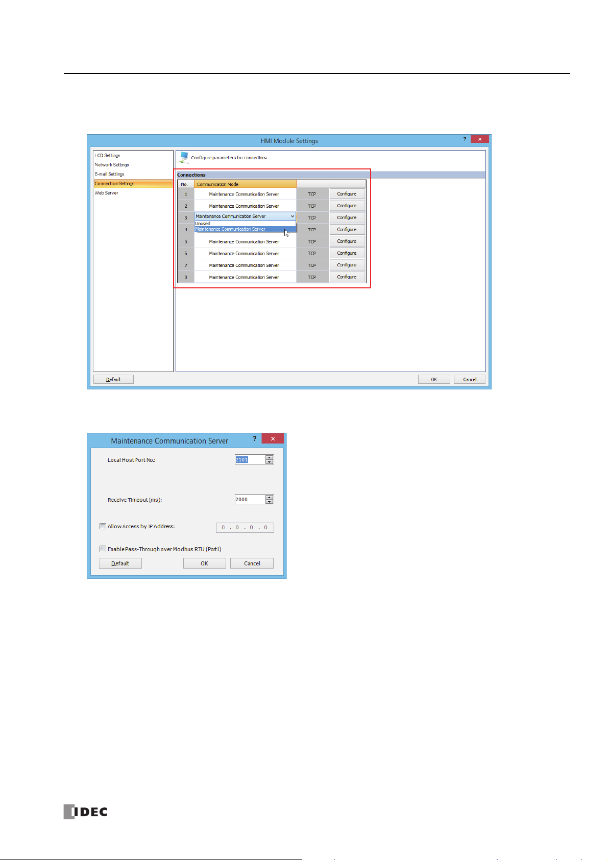
4: M
AINTENANCE COMMUNICATION
4. Click Connection Settings.
5. Click Communication Mode for the port to be used and select communication mode of the connection to use.
6. Set the parameters to match the communication format used by the computer or operator interface.
Local Host Port No. : 2101 (The port number that the FC6A Series MicroSmart uses for the maintenance
communication server)
Receive Timeout (ms) : 2000 (100 to 25500)
Allow Access by IP Address : Disabled (Enabling this option makes it possible to prevent access from devices having any IP
addresses other than the one entered.)
Note: The number of clients that can be connected to the FC6A Series MicroSmart simultaneously is one client per connection. If connections 1 to
8 are all set to the maintenance communication server, eight clients can connect to the FC6A Series MicroSmart at the same time.
7. Click OK.
This completes maintenance communications settings.
FC6A S
ERIES MICROSMART ALL-IN-ONE TYPE COMMUNICATION MANUAL
FC9Y-B1730 4-15

4: M
AINTENANCE COMMUNICATION
4-16 FC6A S
ERIES MICROSMART ALL-IN-ONE TYPE COMMUNICATION MANUAL
FC9Y-B1730

5: U
Introduction
This chapter describes user communication to send and receive specific data by converting it to data types for external devices
connected to the FC6A Series MicroSmart.
The user communication instructions are used to execute user communication.
The user communication instructions differ according to the communication interface that will be used.
• When performing user communication with an external device using port 1 to port 3 via serial communication (RS232C/RS485)
"TXD (Transmit)" on page 5-2
"RXD (Receive)" on page 5-10
• When performing user communication with an external device using Ethernet port 1 via Ethernet communication
"ETXD (User Communication Transmit over Ethernet)" on page 5-23
"ERXD (User Communication Receive over Ethernet)" on page 5-23
User communication allows the following two types of communication methods:
• Serial communication with an external device connected to port 1 to port 3 (RS232C/RS485)
• Ethernet communication with an external device connected by the Ethernet port 1
SER
C
OMMUNICATION INSTRUCTIONS
FC6A S
ERIES MICROSMART ALL-IN-ONE TYPE COMMUNICATION MANUAL
FC9Y-B1730 5-1

5: U
TXD
*
S1
*****D1*****D2*****
SER COMMUNICATION INSTRUCTIONS
TXD (Transmit)
The transmit data is converted to the set data type and transmitted to the external
device using port 1 to 3.
Valid Devices
Device Function I Q M R T C D Constant Repeat
S1 (Source 1) Transmit data — — — — — — X X —
D1 (Destination 1) Transmit completion output — X X*1——— — — —
D2 (Destination 2) Transmit status register — — — — — — X
For valid device address ranges, see Chapter 2 "Device Addresses" in the "FC6A Series MicroSmart LAD Programming Manual".
*1 Internal relays M0 through M7997 or M10000 through M17497 can be designated as D1. Special internal relays cannot be designated as D1.
*2 Special data registers cannot be used.
Transmit data designated by device S1 can be a maximum of 1,536 bytes.
When transmission is complete, an output or internal relay, designated by device D1, is turned on.
Destination 2 occupies two consecutive data registers starting with the device designated by D2. The transmit status data register, D0000-D7998
and D10000-D55998, stores the status of transmission and error code. The next data register stores the byte count of transmitted data. The same
data registers cannot be used as transmit status registers for TXD1 through TXD3 instructions and receive status registers for RXD1 through RXD3
instructions.
The TXD instructions cannot be used in an interrupt program. If used, a user program execution error will result, turning on special internal relay
M8004 and the ERR LED on the FC6A Series MicroSmart. For details about the user program execution errors, see Chapter 3 "User Program
Execution Errors" in the "FC6A Series MicroSmart LAD Programming Manual".
*2
——
Precautions for Programming TXD Instruction
• The FC6A Series MicroSmart has five formatting areas each for executing TXD1 through TXD3 instructions, so five instructions each of TXD1 through TXD3
can be processed at the same time. If inputs to more than five of the same TXD instructions are turned on at the same time, an error code is set to the
transmit status data register, designated by device D2, in the excessive TXD instructions that cannot be executed.
• If the input for a TXD instruction turns on on while another TXD instruction is executed, the subsequent TXD instruction is executed 2 scan times after the
preceding TXD instruction is completed.
• Since TXD instructions are executed in each scan while input is on, a pulse input from a SOTU or SOTD instruction should be used.
• The data register used to store the transmit/receive status and the transmit/receive data byte count must be different for the TXD instruction and the RXD
instruction.
• The TXD instruction cannot be used in an interrupt program. If used, a user program execution error occurs, the execution of the instruction is canceled,
and the next instruction is executed. For details about the user program execution errors, see Chapter 3 "User Program Execution Errors" in the "FC6A
Series MicroSmart LAD Programming Manual".
5-2 FC6A S
ERIES MICROSMART ALL-IN-ONE TYPE COMMUNICATION MANUAL
FC9Y-B1730

User Communication Transmit Instruction Dialog Box in WindLDR
Selections and Devices in Transmit Instruction Dialog Box
5: U
SER COMMUNICATION INSTRUCTIONS
Type
Port No. Port 1 - Port 3 Transmit user communication from port 1 (TXD1) through port 3 (TXD3)
S1 Source 1
D1 Destination 1 Transmit completion output can be an output or internal relay.
D2 Destination 2
TXD Transmit instruction
RXD Receive instruction
Enter the data to transmit in this area.
Transmit data can be constant values (character or hexadecimal), data registers, or BCC.
Transmit status register can be data register D0000-D7998 or D10000-D55998.
The next data register stores the byte count of transmitted data.
FC6A S
ERIES MICROSMART ALL-IN-ONE TYPE COMMUNICATION MANUAL
FC9Y-B1730 5-3

5: U
SER COMMUNICATION INSTRUCTIONS
Transmit Data
Transmit data is designated by source device S1 using constant values or data registers. BCC code can also be calculated
automatically and appended to the transmit data. One TXD instruction can transmit a maximum of 1,536 bytes of data.
S1 (Source 1)
Transmit Data Device Conversion Type
Constant
(Character)
Constant
(Hexadecimal)
Data Register
BCC —
Note: Total byte count of the transmit data is shown in S1 of TXD instruction on the ladder diagram of WindLDR.
0-255 No conversion 1 — — —
D0000-D7999
D10000-D55999
A: Binary to ASCII
B: BCD to ASCII
–: No conversion
A: Binary to ASCII
–: No conversion
Transmit Digits
(Bytes)
1-4
1-5
1-2
1-2 —
Repeat BCC Calculation
1-99 — —
X: XOR
A: ADD
C: Add-2comp
M: Modbus ASCII
M: Modbus RTU
Calculation
Start Position
1-15
Designating Constant as S1
When a constant value is designated as source device S1, one-byte data is transmitted without conversion. The valid transmit data
value depends on the data bits selected in the Communication Parameters dialog box. These data bits are set in
Comm. Ports
, followed by selecting User Protocol in Port 1 through Port 3 list box and clicking the Configure button. When 7
Configuration >
data bits are selected as default, 00h through 7Fh is transmitted. When 8 data bits are selected, 00h through FFh is transmitted.
Constant values are entered in character or hexadecimal notation into the source data.
Constant (Character)
Any character available on the computer keyboard can be entered. One character is counted as one byte.
Constant (Hexadecimal)
Use this option to enter the hexadecimal code of any ASCII character. ASCII control codes NUL (00h) through US (1Fh) can also be entered using
this option.
Example:
The following example shows two methods to enter 3-byte ASCII data “1” (31h), “2” (32h), “3” (33h).
(1) Constant (Character)
(2) Constant (Hexadecimal)
5-4 FC6A S
ERIES MICROSMART ALL-IN-ONE TYPE COMMUNICATION MANUAL
FC9Y-B1730

5: U
Binary to ASCII conversion
When transmitting 4 digits
000Ch
D10
“0”
(30h)
“0”
(30h)
“0”
(30h)
“C”
(43h)
ASCII Data
When transmitting 5 digits
BCD to ASCII conversion
Decimal value
000Ch
D10
“0”
(30h)
“0”
(30h)
“0”
(30h)
“1”
(31h)
“2”
(32h)
00012
ASCII Data
No conversion
When transmitting 2 digits
000Ch
D10
NUL
(00h)FF(0Ch)
ASCII Data
010Ch
D10
“0”
(30h)
“1”
(31h)
“0”
(30h)
“C”
(43h)
“0”
(30h)
“C”
(43h)
ASCII Data
Binary to ASCII conversion
Transmitted Data
Lowest 2 digits
010Ch
D10
Decimal
“0”
(30h)
“0”
(30h)
“2”
(32h)
“6”
(36h)
“8”
(38h)
“2”
(32h)
“6”
(36h)
“8”
(38h)
BCD to ASCII
00268
value conversion
Transmitted DataASCII Data
010Ch
D10
No conversion
SOH
(01h)FF(0Ch)
FF
(0Ch)
Lowest 1 digit
ASCII Data
Tra n s mit t e d Data
SER COMMUNICATION INSTRUCTIONS
Designating Data Register as S1
When a data register is designated as source device S1, conversion type and transmit digits must also be assigned. The data
stored in the designated data register is converted and the assigned quantity of digits of the resultant data is transmitted. The
conversion types that are available are: Binary to ASCII, BCD to ASCII, and no conversion.
When repeat is designated, data of data registers as many as the repeat cycles are transmitted, starting with the designated data
register. Repeat cycles can be up to 99.
Conversion Type
The transmit data is converted according to the designated conversion type as described below:
Example: D10 stores 000Ch (12)
(1) Binary to ASCII conversion
(2) BCD to ASCII conversion
(3) No conversion
Transmit Digits (Bytes)
After conversion, the transmit data is taken out in specified digits. Possible digits depend on the selected conversion type.
Example: D10 stores 010Ch (268)
(1) Binary to ASCII conversion, Transmit digits = 2
(2) BCD to ASCII conversion, Transmit digits = 3
(3) No conversion, Transmit digits = 1
FC6A S
ERIES MICROSMART ALL-IN-ONE TYPE COMMUNICATION MANUAL
FC9Y-B1730 5-5

5: U
000Ch
D10
0022h
D11
0038h
D12
Data register No.:
Transmit digits:
Conversion type:
D10
2
BCD to ASCII
000Ch
D10
“1”
(31h)
“2”
(32h)
“3”
(33h)
“4”
(34h)
00012
Repeat 1
0022h
D11
Decimal value
00034
BCD to ASCII conversion
Repeat 2
ASCII Data
(1) Repeat cycles = 2
000Ch
D10
“1”
(31h)
“2”
(32h)
“3”
(33h)
“4”
(34h)
00012
Repeat 1
0022h
D11
Decimal value
00034
BCD to ASCII conversion
Repeat 2
0038h
D12
00056
Repeat 3
“5”
(35h)
“6”
(36h)
ASCII Data
(2) Repeat cycles = 3
STX
BCC calculation start position can be selected from this range.
1st
“A”
2nd
“B”
3rd
“C”
4th
“D”
5th
“E”
6th
“0”
15thCR16thLF17th
BCC
18th
BCC
19th
BCC calculation range when starting with the 1st byte of the data.
BCC
(2 digits)
SER COMMUNICATION INSTRUCTIONS
Repeat Cycles
When a data register is assigned to repeat, as many consecutive data registers, as the repeat cycles, are used to transmit data in
the same conversion type and transmit digits.
Example:
Data from data registers starting with D10 is converted in BCD to ASCII and is transmitted according to the designated repeat
cycles.
BCC (Block Check Character)
Block check characters can be appended to the transmit data. The start position for the BCC calculation can be selected from the
first byte through the 15th byte. The BCC can be 1 or 2 digits.
5-6 FC6A S
ERIES MICROSMART ALL-IN-ONE TYPE COMMUNICATION MANUAL
FC9Y-B1730

5: U
STX
BCC calculation range
1st
“A”
2nd
“B”
3rd
“C”
4th
“D”
5th
“E”
6th
“0”
15thCR16thLF17th
BCC
18th
BCC
19th
BCC
(2 digits)
STX
BCC calculation range
1st
“A”
2nd
“B”
3rd
“C”
4th
“D”
5th
“E”
6th
“0”
15thCR16thLF17th
BCC
18th
BCC
19th
BCC
(2 digits)
ASCII Data
“A”
(41h)
“B”
(42h)
“C”
(43h)
“D”
(44h)
SER COMMUNICATION INSTRUCTIONS
BCC Calculation Start Position
The start position for the BCC calculation can be specified from the first byte through the 15th byte. The BCC is calculated for the
range starting at the designated position up to the byte immediately before the BCC of the transmit data.
Example: Transmit data consists of 17 bytes plus 2 BCC digits.
(1) Calculation start position = 1
(2) Calculation start position = 2
BCC Calculation Formula
BCC calculation formula can be selected from XOR (exclusive OR), ADD (addition), ADD-2comp, Modbus ASCII, or Modbus RTU.
Example: Conversion results of transmit data consist of 41h, 42h, 43h, and 44h.
(1) BCC calculation formula = XOR
Calculation result = 41h ⊕ 42h ⊕ 43h ⊕ 44h = 04h
(2) BCC calculation formula = ADD
Calculation result = 41h + 42h + 43h + 44h = 10Ah → 0Ah (Only the last 1 or 2 digits are used as BCC.)
(3) BCC calculation formula = ADD-2comp
Calculation result = FEh, F6h (2 digits without conversion)
(4) BCC calculation formula = Modbus ASCII
Calculation result = 88 (ASCII)
(5) BCC calculation formula = Modbus RTU
Calculation result = 85h 0Fh (binary)
FC6A S
ERIES MICROSMART ALL-IN-ONE TYPE COMMUNICATION MANUAL
FC9Y-B1730 5-7

5: U
0041h
Binary to ASCII conversion
“4”
(34h)
“1”
(31h)
2 digits
ASCII Data
D0010:
0041h
No conversion
NUL
(00h)
“A”
(41h)
2 digits
ASCII Data
D0010:
(1) BCC digits = 2
“4”
(34h)
“1”
(31h)
“4”
(34h)
“1”
(31h)
(2) BCC digits = 1
“4”
(34h)
“1”
(31h)
“1”
(31h)
Lower digit
ASCII Data
SER COMMUNICATION INSTRUCTIONS
Conversion Type
The BCC calculation result is converted or not according to the designated conversion type as described below:
Example: BCC calculation result is 0041h.
(1) Binary to ASCII conversion
Note: On WindLDR, Modbus ASCII is defaulted to
binary to ASCII conversion.
(2) No conversion
Note: On WindLDR, Modbus RTU is defaulted to no
conversion.
BCC Digits (Bytes)
The quantity of digits (bytes) of the BCC code can be selected from 1 or 2.
Example:
Note: On WindLDR, Modbus ASCII and Modbus RTU
are defaulted to 2 digits.
D1 (Destination 1)
Set an internal relay or an output for the transmit completion output.
When the start input for a TXD instruction is turned on, preparation for transmission is initiated, followed by data transmission.
When this sequence of operations is complete, the transmit completion output is turned on.
D2 (Destination 2)
Set the data register in which to store the transmit status and the transmit data byte count.
The transmit status is stored in D2+0 and the transmit data byte count is stored in D2+1.
Data registers D0000 through D7998 and D10000 through D55998 can be set.
D2+0 (Transmit Status)
Transmit
Status Code
16 Preparing transmission
32 Tra n s m i tting d a t a
48 Data transmission complete
64 Transmit instruction complete All transmission operation is completed and the next transmission is made possible
Status Description
From turning on the start input for a TXD instruction, until the transmit data is
stored in the internal transmit buffer
From enabling data transmission by an END processing, until all data transmission
is completed
From completing all data transmission, until the END processing is completed for
the TXD instruction
If the transmit status code is other than shown above, a transmit instruction error is suspected. See "User Communication Error"
on page 5-43.
5-8 FC6A S
ERIES MICROSMART ALL-IN-ONE TYPE COMMUNICATION MANUAL
FC9Y-B1730

5: U
D100
Transmit status
D101
Transmit data byte count
SER COMMUNICATION INSTRUCTIONS
D2+1 (Transmit Digits (Bytes))
The transmit data byte count is stored in the data register after that set with D2 (D2+1). BCC data is also included in the transmit
data byte count.
The data register next to the device designated for transmit status stores the byte count of data transmitted by the TXD
instruction. When BCC is included in the transmit data, the byte count of the BCC is also included in the transmit data byte count.
Example: Data register D100 is designated as a device for transmit status.
FC6A S
ERIES MICROSMART ALL-IN-ONE TYPE COMMUNICATION MANUAL
FC9Y-B1730 5-9

5: U
S1
*****D1*****D2*****
RXD
*
SER COMMUNICATION INSTRUCTIONS
RXD (Receive)
When input is on, data from an RS232C/RS485 remote terminal received by port 1
through port 3 is converted and stored in data registers according to the receive
format assigned by S1.
Valid Devices
Device Function I Q M R T C D Constant Repeat
S1 (Source 1) Receive format — — — — — — X X —
D1 (Destination 1) Receive completion output — X X*1——— — — —
D2 (Destination 2) Receive status — — — — — — X
For valid device address ranges, see Chapter 2 "Device Addresses" in the "FC6A Series MicroSmart LAD Programming Manual".
*1 Internal relays M0 through M7997 or M10000 through M17497 can be designated as D1. Special internal relays cannot be designated as D1.
*2 Special data registers cannot be used.
Receive format designated by device S1 can be a maximum of 1,536 bytes.
When data receive is complete, an output or internal relay, designated by device D1, is turned on.
Destination 2 occupies two consecutive data registers starting with the device designated by D2. The receive status data register, D0000-D7998 or
D10000-D55998, stores the status of data receive and error code. The next data register stores the byte count of received data. The same data
registers can not be used as transmit status registers for TXD1 through TXD3 instructions and receive status registers for RXD1 through RXD3
instructions.
The RXD instructions cannot be used in an interrupt program. If used, a user program execution error will result, turning on special internal relay
M8004 and the ERR LED on the FC6A Series MicroSmart. For details about the user program execution errors, see Chapter 3 "User Program
Execution Errors" in the "FC6A Series MicroSmart LAD Programming Manual".
*2
——
Precautions for Programming the RXD Instruction
• The FC6A Series MicroSmart can execute a maximum of five instructions each of RXD1 through RXD3 that have a start delimiter at the same
time. If a start delimiter is not programmed in RXD1 through RXD3 instructions, the FC6A Series MicroSmart can execute only one instruction
each of RXD1 through RXD3 at a time. If the start input for a RXD1 through RXD3 instruction is turned on while another RXD1 through RXD3
instruction, without a start delimiter is executed, a user communication error occurs.
• Since RXD instructions are executed in each scan while input is on, a pulse input from a SOTU or SOTD instruction should be used.
• Once the input to the RXD instruction is turned on, the RXD is activated and ready for receiving incoming communication even after the input is
turned off. When the RXD completes data receiving, the RXD is deactivated if the input to the RXD is off. Or, if the input is on, the RXD is made
ready for receiving another communication. Special internal relays are available to deactivate all RXD instructions waiting for incoming
communication. For user communication receive instruction cancel flags, see "User Communication Receive Instruction Cancel Flag" on page 5-22.
User Communication Receive Instruction Dialog Box in WindLDR
Selections and Devices in Receive Instruction Dialog Box
Type
Port No. Port 1 - Port 3 Receive user communication to port 1 (RXD1) through port 3 (RXD3)
S1 Source 1
D1 Destination 1 Receive completion output can be an output or internal relay.
D2 Destination 2
5-10 FC6A S
TXD Transmit instruction
RXD Receive instruction
Enter the receive format in this area.
The receive format can include a start delimiter, data register to store incoming data, constants, end
delimiter, BCC, and skip.
Receive status register can be data register D0000-D7998 or D10000-D55998.
The next data register stores the byte count of received data.
ERIES MICROSMART ALL-IN-ONE TYPE COMMUNICATION MANUAL
FC9Y-B1730

5: U
Delimiter
SER COMMUNICATION INSTRUCTIONS
Receive Format
Receive format, designated by source device S1, specifies data registers to store received data, data digits for storing data, data
conversion type, and repeat cycles. A start delimiter and an end delimiter can be included in the receive format to discriminate
valid incoming communication. When some characters in the received data are not needed, “skip” can be used to ignore a
specified number of characters. BCC code can also be appended to the receive format to verify the received data. One RXD
instruction can receive 200 bytes of data at the maximum.
S1 (Source 1)
Receive
Format
Data
Register
Start
Delimiter
End
Delimiter
Constant
for
Verification
BCC —1-2
Skip — — — — — — 1-99
Note: Total byte count of the receive format is shown in S1 of RXD instruction on the ladder diagram of WindLDR.
Device
D0000-D7999
D10000D55999
00h-FFh
1 to 5 bytes
00h-FFh — No conversion — — — —
00h-FFh — No conversion — — — —
Receive
Digits
(Bytes)
1-4
1-5
1-2
— No conversion — — — —
Conversion
Type
A:ASCII to Binary
B:ASCII to BCD
–:No conversion
A:Binary to ASCII
–:No conversion
Repeat
1-99 — — —
—
BCC
Calculation
X:XOR
A:ADD
C:Add-2comp
M:Modbus ASCII
M:Modbus RTU
Calculation
Start
Position
1-15 —
Skip
Bytes
Delimiter
Hex
ASCII
Designating Data Register as S1
When a data register is designated as source device S1, receive digits and conversion type must also be assigned. The received
data is divided into blocks of specified receive digits, converted in a specified conversion type, and stored to the designated data
registers. Conversion types are available in ASCII to Binary, ASCII to BCD, and no conversion.
When repeat is designated, received data is divided, converted, and stored into as many data registers as the repeat cycles,
starting with the designated data register. There can be up to 99 repeat cycles.
When a data register is designated as source device S1, a delimiter can be included in the data register designation to end
receiving communication.
FC6A S
ERIES MICROSMART ALL-IN-ONE TYPE COMMUNICATION MANUAL
FC9Y-B1730 5-11

5: U
“1”
(31h)
“2”
(32h)
“3”
(33h)
“4”
(34h)
2 digits
“5”
(35h)
“6”
(36h)
2 digits
2 digits
1st block 2nd block 3rd block
“1”
(31h)
“2”
(32h)
“3”
(33h)
“4”
(34h)
3 digits
“5”
(35h)
“6”
(36h)
3 digits
1st block 2nd block
0012h
ASCII to Binary conversion
“1”
(31h)
“2”
(32h)
00012
ASCII to BCD conversion
“1”
(31h)
“2”
(32h)
000Ch
Hexadecimal value
3132h
No conversion
“1”
(31h)
“2”
(32h)
0012h
D20
Repeat 1
0034h
D21
ASCII to Binary conversion
Repeat 2
“1”
(31h)
“2”
(32h)
2 digits
1st block
“3”
(33h)
“4”
(34h)
2 digits
2nd block
0012h
D20
Repeat 1
0034h
D21
ASCII to Binary conversion
Repeat 2
“1”
(31h)
“2”
(32h)
2 digits
1st block
“3”
(33h)
“4”
(34h)
2 digits
2nd block
“5”
(35h)
“6”
(36h)
2 digits
3rd block
0056h
D22
Repeat 3
SER COMMUNICATION INSTRUCTIONS
Receive Digits
The received data is divided into blocks of specified receive digits before conversion as described below:
Example: Received data of 6 bytes are divided in different receive digits. (Repeat is also designated.)
(1) Receive digits = 2 (2) Receive digits = 3
Conversion Type
The data block of the specified receive digits is then converted according to the designated conversion type as described below:
Example: Received data has been divided into a 2-digit block.
(1) ASCII to Binary conversion
(2) ASCII to BCD conversion
(3) No conversion
Repeat Cycles
When a data register is assigned to repeat, the received data is divided and converted in the same way as specified, and the converted data is
stored to as many consecutive data registers as repeat cycles.
Example: Received data of 6 bytes is divided into 2-digit blocks, converted in ASCII to Binary, and stored to data registers starting
at D20.
(1) Repeat cycles = 2
(2) Repeat cycles = 3
5-12 FC6A S
ERIES MICROSMART ALL-IN-ONE TYPE COMMUNICATION MANUAL
FC9Y-B1730

5: U
****
h
D100
When D100 is designated as the first data register
“0”
(30h)
“1”
(31h)
1st
character
“2”
(32h)
“3”
(33h)
Incoming Data
****
h
D100+n
****
h
D101
The incoming data is divided, converted, and stored to data registers according to the receive format.
****
h
D100
RXD Instruction 1
STX
(02h)
“1”
(31h)
“2”
(32h)
“3”
(33h)
Incoming Data
****
h
D100+n
****
h
D101
The incoming data is divided, converted, and stored to data registers according to the receive format.
Start delimiters are not stored to data registers.
ENQ
(05h)
“A”
(41h)
“B”
(42h)
“C”
(43h)
STX (02h)
When D100 is designated as the first data register
****
h
D200
RXD Instruction 2
****
h
D200+n
****
h
D201
ENQ (05h)
When D200 is designated as the first data register
Compare
SER COMMUNICATION INSTRUCTIONS
Delimiter
A delimiter for the data register in the receive format can be assigned. Using a delimiter, incoming data of variable length can be
received and stored to data registers.
Delimiter How the incoming data is stored to data registers
Designated
No delimiter
Note: Delimiters for data registers can be used in the receive format of RXD instructions only.
The incoming data is stored to data registers until all the data specified with receive digits, conversion type, and repeat
is processed or the specified delimiter is received.
The incoming data is stored to data registers until all the data specified with receive digits, conversion type, and repeat
is processed.
Designating Constant as Start Delimiter
A start delimiter can be programmed at the first byte in the receive format of a RXD instruction; the FC6A Series MicroSmart will
recognize the beginning of valid communication, although a RXD instruction without a start delimiter can also be executed.
When a constant value is designated at the first byte of source device S1, the one-byte data serves as a start delimiter to start the
processing of the received data.
A maximum of five instructions each of RXD1 through RXD3 with different start delimiters can be executed at the same time.
When the first byte of the incoming data matches the start delimiter of a RXD instruction, the received data is processed and
stored according to the receive format specified in the RXD instruction. If the first byte of the incoming data does not match the
start delimiter of any RXD instruction that is executed, the FC6A Series MicroSmart discards the incoming data and waits for the
next communication.
When a RXD instruction without a start delimiter is executed, any incoming data is processed continuously according to the receive
format. Only one instruction each of RXD1 through RXD3 without a start delimiter can be executed at a time. If start inputs to two
or more RXD instructions without a start delimiter are turned on simultaneously, the one at the smallest address is executed and
the corresponding completion output is turned on.
Example:
(1) When a RXD instruction without a start delimiter is executed
(2) When RXD instructions with start delimiters STX (02h) and ENQ (05h) are executed
FC6A S
ERIES MICROSMART ALL-IN-ONE TYPE COMMUNICATION MANUAL
FC9Y-B1730 5-13

5: U
Data Register, Skip, or BCC
Receive Format
Start Delimiter
Receive Format
Const
Start
Delimiter
DR
etc.
Const Const Const
Data Register, Skip, or BCC
DR
etc.
Start Delimiter
Receive Format
Const Const Const Const Const Const
S1
16
D1
M20
I0
SOTU
RXD
1
D2
D200
Communication port: Port 1
Receive completion output: M20
Receive status register: D200
Receive data byte count: D201
Receive Format S1
32
D200
OFF
M20
Const
(05h)
Start
Delimiter
DR
D210
Const
(05h)
S1
16
D1
M30
I1
SOTU
RXD
1
D2
D300
Communication port: Port 1
Receive completion output: M30
Receive status register: D300
Receive data byte count: D301
5
D300
OFF
M30
Receive Format S1
Const
(05h)
Start
Delimiter
DR
D310
Const
(0Ah)
SER COMMUNICATION INSTRUCTIONS
Multi-byte Start Delimiter
A start delimiter can be programmed at the first bytes in the receive format of a RXD instruction; the FC6A Series MicroSmart will
recognize the beginning of valid communication, although a RXD instruction without a start delimiter can also be executed. A
maximum of 5 consecutive constants that are either character or hexadecimal from the first byte of the receive format are
considered a multi-byte start delimiter.
If a RXD instruction with a start delimiter is executed and another RXD instruction with the same start delimiter is executed, user
communication error code 5 is stored in the data register designated as the receive status of the second RXD instruction. When the
error occurs, the second RXD instruction is canceled, and the first RXD instruction executed is kept.
If a multi-byte start delimiter is assigned, and the incoming data does not match the entire multi-byte start delimiter, the FC6A
Series MicroSmart discards the incoming data and waits for the next communication.
When the first one byte is received, a timer is started to monitor the interval between incoming data even when a multi-byte start
delimiter is assigned. If data is not received in the period specified for the receive timeout value after receiving one byte of data, a
receive timeout error occurs, and user communication error code 11 is stored in the status data register.
Examples: Multi-byte Start Delimiter
Multi-byte start delimiter is determined in the structure of the Receive Format. The following examples show how multi-byte start
delimiter is determined.
• Constants are followed by data register, skip, or BCC
Note: Constants following data register, skip, or BCC are not considered start delimiter even if these are in the first five bytes of the receive format.
• More than 5 constants are specified from the first byte
Note: Constants that are neither start delimiters or end delimiters are considered constants for verification. See "Constant for Verification" on page
5-17.
Example: Start Delimiter Duplication Error
When input I0 is turned on, the first RXD instruction is executed and status code 32 is stored in the receive status D200, indicating
the RXD instruction is waiting for the incoming data. When input I1 is turned on, another RXD instruction is executed, but since
two RXD instructions have the same start delimiter, the second RXD instruction is not executed, and user communication error
code 5 is stored in the receive status D300.
5-14 FC6A S
ERIES MICROSMART ALL-IN-ONE TYPE COMMUNICATION MANUAL
FC9Y-B1730

5: U
S1
16
D1
M20
RXD
1
D2
D400
Receive Format S1
Const
(01h)
Start
Delimiter
DR
S1
16
D1
M21
RXD
1
D2
D402
Receive Format S1
Const
(01h)
Start Delimiter
Const
(02h)
Skip
S1
16
D1
M22
RXD
1
D2
D404
Receive Format S1
Const
(01h)
Start Delimiter
Const
(02h)
DRConst
(03h)
Const
(04h)
Const
(05h)
STX
(02h) (3xh)
1st
character
(3xh) (3xh) (3xh) (3xh)CR(13h)
Data: 0000 through 9999
Slave Station Number: 0 through 9
Last character
STX
(02h) (3xh)
Start
Delimiter
(3xh) (3xh) (3xh) (3xh)CR(13h)
Stored to D1
Stored to D0
End
Delimiter
SER COMMUNICATION INSTRUCTIONS
Note: If you execute two or more RXD instructions with multi-byte start delimiters simultaneously, the start delimiters of those RXD instructions
must be unique from the others. When the length of the multi-byte start delimiters of the RXD instructions is different, the length of the shortest
one is applied to check the duplicated start delimiters. The start delimiter of any of two RXD instructions in the following RXD instructions are
considered the same.
Example: Using Multi-byte Start Delimiter
The following example shows the advantages of using a multi-byte start delimiter rather than a single-byte start delimiter. A RXD
instruction processes incoming data from the master station. The incoming data is sent to multiple slave stations 0 through 9, and
the local slave station number is 1. Therefore, incoming data from the master station must be received only when the incoming
data is sent for the slave station 1.
• Incoming data
Incoming data consists of start delimiter STX, a slave station number which can be 0 through 9, data 0000 through 9999, and end
delimiter CR.
• Single-byte start delimiter
Only the first byte can be the start delimiter. The second byte of the incoming data, which is the slave station number, has to be
stored to data register D0, and extra ladder programming is needed to see whether the slave station number of the incoming
communication is 1 or not. Only when the slave station number is 1, received data stored in D1 is valid for the local PLC.
FC6A S
ERIES MICROSMART ALL-IN-ONE TYPE COMMUNICATION MANUAL
FC9Y-B1730 5-15
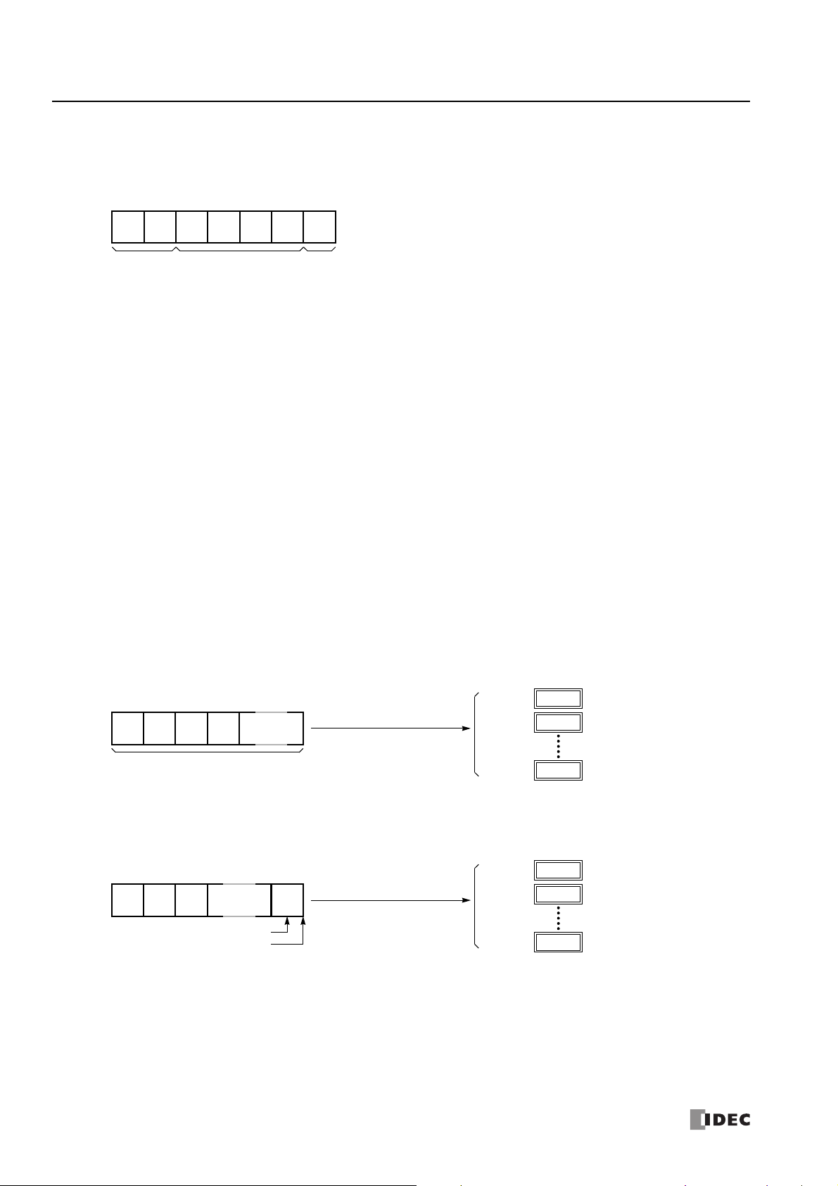
5: U
STX
(02h)
“1“
(31h)
Start
Delimiter
(3xh) (3xh) (3xh) (3xh)CR(13h)
Stored to D1
End
Delimiter
****
h
D100
When D100 is designated
“0”
(30h)
“1”
(31h)
Total of received characters
“2”
(32h)
“3”
(33h)
Incoming Data
****
h
D100+n
****
h
D101
The incoming data is divided, converted, and stored to data registers according to the receive format.
Receive operation is completed when the total characters programmed in RXD are received.
as the first data register
****
h
D100
When D100 is designated
ETX
(03h)
“1”
(31h)
End Delimiter
“2”
(32h)
“3”
(33h)
Incoming Data
****
h
D100+n
****
h
D101
The incoming data is divided, converted, and stored to data registers according to the receive format.
The end delimiter is not stored to a data register.
Any data arriving after the end delimiter is discarded.
as the first data register
End of receiving data
SER COMMUNICATION INSTRUCTIONS
• Multi-byte start delimiter
First two bytes can be configured as a multi-byte start delimiter. The incoming data is processed according to the receive format
only when the first two bytes of the incoming data match the start delimiter. Therefore, only the incoming data sent to slave
station 1 is processed. No extra ladder programming is needed to check the slave station number.
Designating Constant as End Delimiter
An end delimiter can be programmed at the end of the receive format of a RXD instruction; the FC6A Series MicroSmart will
recognize the end of valid communication, although RXD instructions without an end delimiter can also be executed.
When a constant value is designated at the end of source device S1, the one-byte data serves as an end delimiter to end the
processing of the received data. If data bits are set to 7 bits, the end delimiters will be between 00h and 7Fh. If data bits are set
to 8 bits, the end delimiters will be between 00h and FFh. Constant values are entered in character or hexadecimal notation into
the source data. When using the same RXD instruction repeatedly in a user program, assign different end delimiters for each RXD
instruction.
If a character in incoming data matches the end delimiter, the RXD instruction ends receiving data at this point and starts
subsequent receive processing as specified. Even if a character matches the end delimiter at a position earlier than expected, the
RXD instruction ends receiving data there.
If a BCC code is included in the receive format of a RXD instruction, an end delimiter can be positioned immediately before or after
the BCC code. If a data register or skip is designated between the BCC and end delimiter, correct receiving is not ensured.
When a RXD instruction without an end delimiter is executed, data receiving ends when the specified bytes of data in the receive
format, such as data registers and skips, have been received. In addition, data receiving also ends when the interval between
incoming data characters exceeds the receive timeout value specified in the Communication Parameters dialog box whether the
RXD has an end delimiter or not. The character interval timer is started when the first character of incoming communication is
received and restarted each time the next character is received. When a character is not received within a predetermined period of
time, timeout occurs and the RXD ends data receive operation.
Example:
(1) When a RXD instruction without an end delimiter is executed
(2) When a RXD instruction with end delimiter ETX (03h) and without BCC is executed
5-16 FC6A S
ERIES MICROSMART ALL-IN-ONE TYPE COMMUNICATION MANUAL
FC9Y-B1730

5: U
****
h
D100
When D100 is designated
ETX
(03h)
“1”
(31h)
End Delimiter
“2”
(32h)
BCC
Code
Incoming Data
****
h
D100+n
****
h
D101
The incoming data is divided, converted, and stored to data registers according to the receive format.
The end delimiter and BCC code are not stored to data registers.
After receiving the end delimiter, the FC6A Series MicroSmart receives only the one-byte BCC code.
as the first data register
End of receiving data
STX
(02h) (3xh)
Start
Delimiter
(3xh)
“1“
(31h) (3xh) (3xh)CR(13h)
Stored to D1 through D5
End
Delimiter
STX
(02h) (3xh)
Start
Delimiter
(3xh)
“1“
(31h) (3xh) (3xh)CR(13h)
Stored to D3 and D4
End
Delimiter
Constant
Stored to D1 and D2
SER COMMUNICATION INSTRUCTIONS
(3) When a RXD instruction with end delimiter ETX (03h) and one-byte BCC is executed
Constant for Verification
Constants excluding start and end delimiters can be configured in the receive format to verify the incoming data with the
constants, which are either characters or hexadecimal values. As many constants can be configured for the verification as required.
The verification result is stored in the receive status of the RXD instruction.
Example: Programming Constant for Verification
The following example shows the advantage of using constant for verification. The incoming data contains a constant value “1” in
the middle, and that constant value needs to be verified to see whether the incoming data is valid.
• Using Data Register
The incoming data including the constant value needs to be stored in data registers. When the RXD instruction completes receiving
the incoming data, the receive status contains 64, meaning the RXD instruction has completed without errors, even if the constant
value is not an expected value. Extra ladder programming is needed to see whether the constant value in the incoming data is
correct or not.
• Using Constant for Verification
A constant to verify the constant value in the incoming data is designated in the receive format. If the constant value is not an
expected value when the RXD instruction completes receiving the incoming data, the receive status contains 74, meaning the RXD
instruction has completed but user communication error code 5 occurred. No extra ladder programming is needed to see whether
the constant value in the received data is correct or not.
Note: When configuring constants, which are either characters or hexadecimal values, in the receive format, and the incoming data does not match
the constants in the receive format, then a user communication error code is stored in the receive status. The error code contained in the receive
status depends on whether the constants are used as a start delimiter or as constants for verification. If used as a start delimiter, user
communication error code 7 is stored in the receive status, and the RXD instruction keeps waiting for valid incoming data. On the other hand, if used
as constants for verification, the receive status contains 74, and the RXD instruction finishes the execution. To repeat receiving incoming
communication, turn on the input for the RXD instruction.
FC6A S
ERIES MICROSMART ALL-IN-ONE TYPE COMMUNICATION MANUAL
FC9Y-B1730 5-17
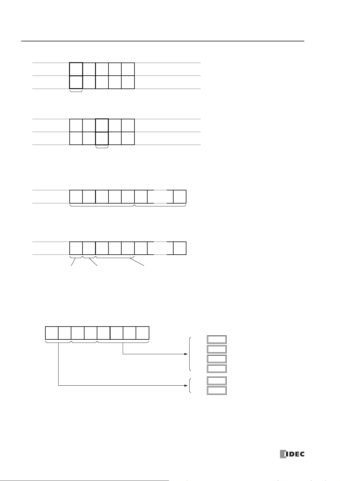
5: U
Incoming Data
Receive Format
Const
(02h) (xxh)
Start
Delimiter
(FFh)
(xxh)
(0Dh)
Const
(05h)
DR Const
(FFh)
DR Const
(0Dh)
Incoming Data
Receive Format
Receive status:
Receive completion output: 70
•
Start delimiter of incoming data does not match the receive format
RXD instruction keeps waiting for valid incoming data,
and completes data receiving after receiving valid data
including a correct start delimiter.
(05h)
(xxh)
Constant for
Veri fi ca tion
(0Fh)
(xxh)
(0Dh)
Const
(05h)
DR Const
(FFh)
DR Const
(0Dh)
Receive status:
Receive completion output: 741
•
Constant for verification of incoming data does not match the receive format
Receive status stores 74 (= 64 + 10)
RXD instruction completes data receiving. To repeat
receiving incoming communication, turn on the input for
the RXD instruction.
Receive Format
Constant for Verification
6th byte and after
Const
Receive Format
•
More than five constants are configured in the beginning of the receive format
Byte 1st
Const
2nd
Const
3rd
Const
4th
Const
5th
Const
6th
Const
200th
Start Delimiter
Up to 5th byte
Constant for Verification
Not consecutive in the first 5 bytes
Const
•
Other than constants (data register, skip, or BCC) are included in the first five bytes of the receive format
1st
DR
etc.
2nd
Const
3rd
Const
4th
Const
5th
6th 200th
Start Delimiter
Consecutive first 5 bytes only
Data register,
Byte
skip, or BCC
0035h
D102
“1”
(31h)
“2”
(32h)
Skipped
“3”
(33h)
“4”
(34h)
Incoming Data
0038h
D105
0036h
D103
“5”
(35h)
“6”
(36h)
“7”
(37h)
“8”
(38h)
0031h
D100
0032h
D101
0037h
D104
When D100 is designated
as the first data register
SER COMMUNICATION INSTRUCTIONS
Note: Constants configured in the beginning of receive formats have different functions as shown below:
Skip
When “skip” is designated in the receive format, a specified quantity of digits in the incoming data are skipped and not stored to
data registers. A maximum of 99 digits (bytes) of characters can be skipped continuously.
Example: When a RXD instruction with skip for 2 digits starting at the third byte is executed
5-18 FC6A S
ERIES MICROSMART ALL-IN-ONE TYPE COMMUNICATION MANUAL
FC9Y-B1730

5: U
STX
BCC calculation range
1st
“A”
2nd
“B”
3rd
“C”
4th
“D”
5th
“E”
6th
“0”
15thCR16thLF17th
BCC
18th
BCC
19th
BCC
(2 digits)
STX
BCC calculation range
1st
“A”
2nd
“B”
3rd
“C”
4th
“D”
5th
“E”
6th
“0”
15thCR16thLF17th
BCC
18th
BCC
19th
BCC
(2 digits)
SER COMMUNICATION INSTRUCTIONS
BCC (Block Check Character)
The FC6A Series MicroSmart has an automatic BCC calculation function to detect a communication error in incoming data. If a BCC
code is designated in the receive format of a RXD instruction, the FC6A Series MicroSmart calculates a BCC value for a specified
starting position through the position immediately preceding the BBC. It then compares the calculation result with the BCC code in
the received incoming data. The start position for the BCC calculation can be specified from the first byte through the 15th byte.
The BCC can be 1 or 2 digits.
When an end delimiter is not used in the RXD instruction, the BCC code must be positioned at the end of the receive format
designated in Source 1 device. When an end delimiter is used, the BCC code must be immediately before or after the end delimiter.
The FC6A Series MicroSmart reads a specified number of BCC digits in the incoming data according to the receive format to
calculate and compare the received BCC code with the BCC calculation results.
BCC Calculation Start Position
The start position for the BCC calculation can be specified from the first byte through the 15th byte. The BCC is calculated for the
range starting at the designated position up to the byte immediately before the BCC of the receive data.
Example: Received data consists of 17 bytes plus 2 BCC digits.
(1) Calculation start position = 1
(2) Calculation start position = 2
BCC Calculation Formula
BCC calculation formula can be selected from XOR (exclusive OR), ADD (addition), ADD-2comp, Modbus ASCII, or Modbus RTU.
Example: Incoming data consists of 41h, 42h, 43h, and 44h.
(1) BCC calculation formula = XOR
Calculation result = 41h ⊕ 42h ⊕ 43h ⊕ 44h = 04h
(2) BCC calculation formula = ADD
Calculation result = 41h + 42h + 43h + 44h = 10Ah → 0Ah (Only the last 1 or 2 digits are used as BCC.)
(3) BCC calculation formula = ADD-2comp
Calculation result = FEh, F6h (2 digits without conversion)
(4) BCC calculation formula = Modbus ASCII
Calculation result = 88 (ASCII)
(5) BCC calculation formula = Modbus RTU
Calculation result = 85h 0Fh (binary)
FC6A S
ERIES MICROSMART ALL-IN-ONE TYPE COMMUNICATION MANUAL
FC9Y-B1730 5-19

5: U
0041h
Binary to ASCII conversion
“4”
(34h)
“1”
(31h)
2 digits
D0010:
0041h
No conversion
NUL
(00h)
“A”
(41h)
2 digits
D0010:
(1) BCC digits = 2
“4”
(34h)
“1”
(31h)
“4”
(34h)
“1”
(31h)
(2) BCC digits = 1
“4”
(34h)
“1”
(31h)
“1”
(31h)
Lower digit
“1”
(31h)
“2”
(32h)
BCC calculation range
“3”
(33h)
“4”
(34h)
Incoming Data
“5”
(35h)
“6”
(36h)
“0”
(30h)
“7”
(37h)
BCC
31h ⊕ 32h ⊕ 33h ⊕ 34h ⊕ 35h ⊕ 36h = 07h
“0”
(30h)
“7”
(37h)
BCC Calculation Result
Binary to ASCII Conversion
Comparison result is true to indicate that data
is received correctly.
“1”
(31h)
“2”
(32h)
BCC calculation range
“3”
(33h)
“4”
(34h)
Incoming Data
“5”
(35h)
“6”
(36h)
“0”
(30h)
“7”
(37h)
BCC
31h + 32h + 33h + 34h + 35h + 36h = 135h
“3”
(33h)
“5”
(35h)
BCC Calculation Result
Binary to ASCII Conversion
Comparison result is false.
Error code 9 is stored in the receive status data
register.
SER COMMUNICATION INSTRUCTIONS
Conversion Type
The BCC calculation result can be converted or not according to the assigned conversion type as described below:
Example: BCC calculation result is 0041h.
(1) Binary to ASCII conversion
Note: On WindLDR, Modbus ASCII defaults to binary
to ASCII conversion.
(2) No conversion
Note: On WindLDR, Modbus RTU defaults to no
conversion.
BCC Digits (Bytes)
The quantity of digits (bytes) of the BCC code can be selected from 1 or 2.
Example:
Note: On WindLDR, Modbus ASCII and Modbus RTU
default is set to 2 digits.
Comparing BCC Codes
The FC6A Series MicroSmart compares the BCC calculation result with the BCC code in the received incoming data to check for any error in the
incoming communication due to external noises or other causes. If a disparity is found in the comparison, an error code is stored in the data register
designated as receive status in the RXD instruction. For user communication error code, see "User Communication Error" on page 5-43.
Example 1: BCC is calculated for the first byte through the sixth byte using the XOR format, converted in binary to ASCII, and
compared with the BCC code appended to the seventh and eighth bytes of the incoming data.
Example 2: BCC is calculated for the first byte through the sixth byte using the ADD format, converted in binary to ASCII, and
compared with the BCC code appended to the seventh and eighth bytes of the incoming data.
5-20 FC6A S
ERIES MICROSMART ALL-IN-ONE TYPE COMMUNICATION MANUAL
FC9Y-B1730

5: U
Receive Format
DR1 FFh BCC
1 byte
4 bytes max. + delimiter 1 byte 2 bytes max.
DR2
Delimiter: FFh
Conversion: ASCII to Binary
Digits: 4
Repeat: 1
Delimiter: —
Conversion: None
Digits: 2
Repeat: 1
After delimiter FFh has been received, data receiving is
completed when subsequent 3 bytes are received.
D200
Receive status
D201
Receive data byte count
SER COMMUNICATION INSTRUCTIONS
D1 (Destination 1)
Set an internal relay or an output for the receive completion output.
When the start input for a RXD instruction is turned on, preparation for receiving data is initiated, followed by data conversion and
storage. When the data receive operation sequence
is complete, the designated output or internal relay is turned on.
Conditions for Completion of Receiving Data
After starting to receive data, the RXD instruction can be completed in three ways depending on the designation of end delimiter and delimiter in the receive format.
End Delimiter Delimiter Conditions for Completion of Receiving Data
With With or Without
Without With
Without Without When a specified byte count of data (digits × repeat) has been received.
Note: Whenever a receive timeout has occurred, data receiving stops arbitrarily.
Data receiving is complete when one of the above three conditions is met. To abort a RXD instruction, use the special internal relay for user
communication receive instruction cancel flag. See "User Communication Receive Instruction Cancel Flag" on page 5-22.
Example:
A RXD instruction does not have an end delimiter and has a delimiter programmed in the receive format for data registers.
When a specified byte count of data (digits × repeat) has been received or when an end delimiter is received.
When a BCC exists immediately after the end delimiter, the BCC is received before ending data receiving.
After the last constant (including delimiter) designated in the RXD instruction has been received, data
receiving is completed when the subsequent byte count of data has been received.
D2 (Destination 2)
Set the data register in which to store the receive status and the receive data byte count.
The receive status is stored in D2+0 and the receive data byte count is stored in D2+1.
Data registers D0000 through D7998 and D10000 through D55998 can be set.
D2+0 (Receive Status)
The receive status is stored in the data register set with D2. The receive status includes the reception operation status and the
error information.
Receive Status Code
16 Preparing data receive
32 Receiving data
48 Data receive complete
64 Receive instruction complete All data receive operation is completed and the next data receive is made possible
128
User communication receive
instruction cancel flag active
Status Description
From turning on the start input for a RXD instruction to read the receive format, until
the RXD instruction is enabled by an END processing
From enabling the RXD instruction by an END processing, until incoming data is received
From receiving incoming data, until the received data is converted and stored in data
registers according to the receive format
RXD instructions are cancelled by special internal relay for user communication
receive instruction cancel flag, such as M8022, M8023 or M8026
If the receive status code is other than shown above, a receive instruction error is suspected. See "User Communication Error" on
page 5-43.
D2+1 (Receive Digits (Bytes))
The data register next to the device designated for receive status stores the byte count of data received by the RXD instruction.
When a start delimiter, end delimiter, and BCC are included in the received data, the byte counts for these codes are also included
in the receive data byte count.
Example: Data register D200 is designated as a device for receive status.
FC6A S
ERIES MICROSMART ALL-IN-ONE TYPE COMMUNICATION MANUAL
FC9Y-B1730 5-21

5: U
SER COMMUNICATION INSTRUCTIONS
User Communication Receive Instruction Cancel Flag
If user communication receive instruction cancel is turned on when the receive pre-processing for the user communication receive
instruction has already been completed and data is being received (status code 32), all receive instructions for the corresponding
port will be canceled. This is effective for canceling receive instruction execution when waiting a long time to receive data.
To activate a receive instruction that was canceled, turn off the user communication receive instruction cancel flag, and then turn
on the receive instruction input conditions again.
User communication receive instruction cancel flags are allocated as follows to each communication port as a special internal relay.
Device Address Description CPU Stopped Power OFF R/W
M8022 User Communication Receive Instruction Cancel Flag (Port 1) Cleared Cleared W
M8023 User Communication Receive Instruction Cancel Flag (Port 2) Cleared Cleared W
M8026 User Communication Receive Instruction Cancel Flag (Port 3) Cleared Cleared W
"R/W" is the abbreviation for read/write. When R/W, it can be read and written. When R, it can only be read. When W, it can only be written.
5-22 FC6A S
ERIES MICROSMART ALL-IN-ONE TYPE COMMUNICATION MANUAL
FC9Y-B1730

5: U
ETXD*S1
*****D1*****D2*****
ERXD*S1
*****D1*****D2*****
SER COMMUNICATION INSTRUCTIONS
ETXD (User Communication Transmit over Ethernet)
The ETXD instruction converts transmission data to the specified data type and sends it
to the external device connected over Ethernet.
When the input is on, the transmission data designated by S1 is transmitted to the device connected with the specified connection.
When transmission is complete, the device designated by D1 is turned on. Transmit status (the transmission status and error code) is stored to the
device designated by D2.
The byte count of transmitted data is stored to D2+1.
Apart from the connection settings, the settings of ETXD and TXD instructions are the same. For details on TXD instruction, see "TXD (Transmit)" on
page 5-2.
The ETXD instruction cannot be used in an interrupt program.
If used, a user program execution error will result, turning on special internal relay M8004 and the ERR LED on the FC6A Series MicroSmart. For
details about the user program execution errors, see Chapter 3 "User Program Execution Errors" in the "FC6A Series MicroSmart LAD Programming
Manual".
Note: For details on the user communication client and user communication server specifications and for details on user communication over
Ethernet, see "User Communication via Ethernet Communication" on page 5-35.
ERXD (User Communication Receive over Ethernet)
The ERXD instruction receives data from an external device connected over Ethernet,
converts the received data in the specified format, and stores the converted data to
data registers.
When the input is on, the received data designated by S1 is received from the device connected with the specified connection.
When all data has been received, the device designated by D1 is turned on. Receive status (the receive status and error code) is stored to the device
designated by D2.
The byte count of received data is stored to D2+1.
When user communication receive instruction cancel flag (M8200 - M8207) is turned on while receiving incoming data, the execution of all active
receive instructions for the corresponding connection is canceled.
Apart from the connection settings and the allocation of the user communication receive instruction cancel flags, the settings of ERXD and RXD
instructions are the same. For details on RXD instruction, see "RXD (Receive)" on page 5-10.
The ERXD instruction cannot be used in an interrupt program.
If used, a user program execution error will result, turning on special internal relay M8004 and the ERR LED on the FC6A Series MicroSmart. For
details about the user program execution errors, see Chapter 3 "User Program Execution Errors" in the "FC6A Series MicroSmart LAD Programming
Manual".
Note: For details on the user communication client and user communication server specifications and for details on user communication over
Ethernet, see "User Communication via Ethernet Communication" on page 5-35.
FC6A S
ERIES MICROSMART ALL-IN-ONE TYPE COMMUNICATION MANUAL
FC9Y-B1730 5-23
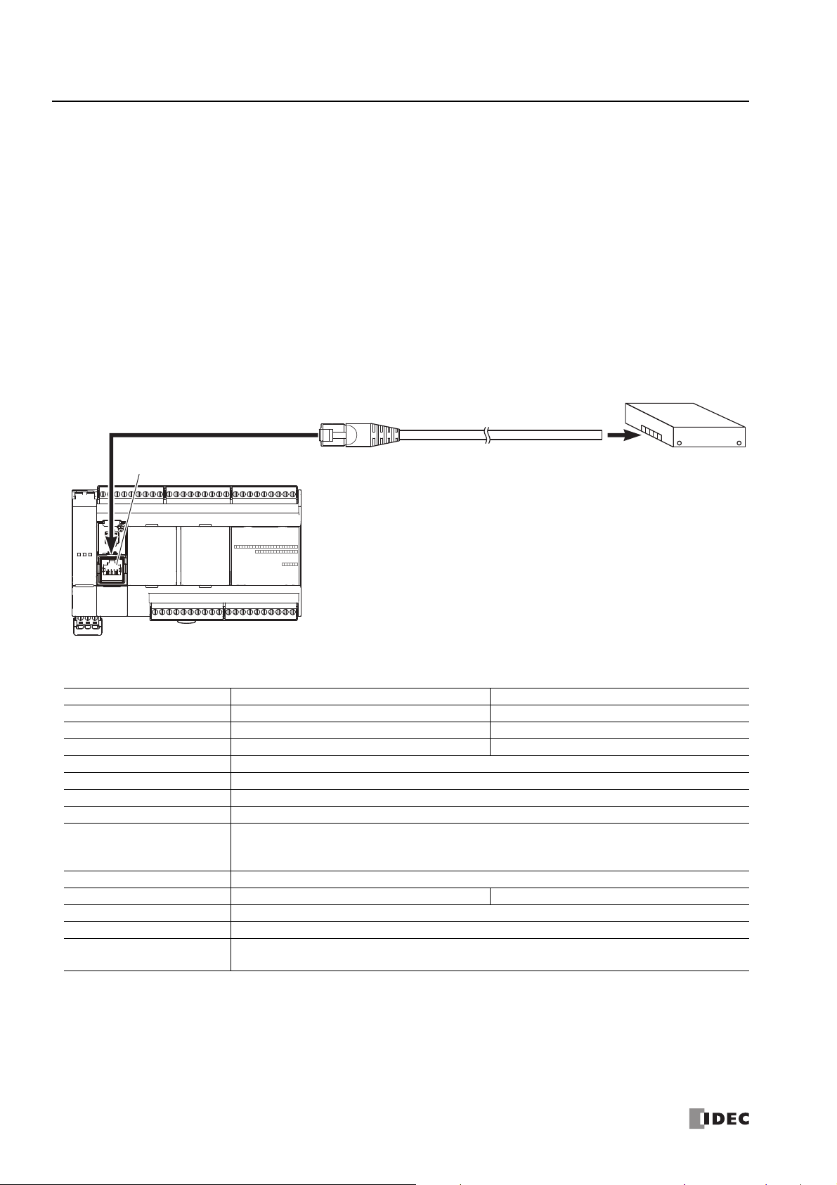
5: U
RS232C Equipment
To Serial Port 1
FC6A Series MicroSmart
To RS232C Port
Attach a proper connector to the open
end of the cable referring to the cable
connector pinouts shown below.
User Communication Cable
FC6A-KC1C
5 m (16.4 ft.) long
Serial Port 1
SER COMMUNICATION INSTRUCTIONS
User Communication via Serial Communication
With user communication via serial communication, the FC6A Series MicroSmart can send and receive data between external
devices connected to port 1 to port 3, such as a printer or barcode reader, by using the TXD (user communication transmit) and
RXD (user communication receive) instructions.
User Communication Overview
By installing a communication cartridge on the FC6A Series MicroSmart expansion communication port, the FC6A Series
MicroSmart can communicate with two external devices simultaneously.
When using an RS485 communication cartridge, FC6A Series MicroSmart modules can communicate with a maximum of 31 RS485
devices using the user communication.
User communication transmit and receive instructions can be programmed to match the communication protocol of the equipment
to communicate with. Possibility of communication using the user communication mode can be determined referring to the user
communication mode specifications described below.
A barcode reader is connected to port 1 of the FC6A Series MicroSmart.
User Communication Mode Specifications
Type RS232C User Communication RS485 User Communication
Communication Port Port 1 to port 3 Port 1 to port 3
Maximum Nodes 1 per port 31 maximum
Standards EIA RS232C EIA RS485
Baud Rate 1,200, 2,400, 4,800, 9,600, 19,200, 38,400, 57,600, 115,200 bps (Default: 115,200)
Data Bits 7 or 8 bits (Default: 7)
Parity Odd, Even, None (Default: Even)
Stop Bits 1 or 2 bits (Default: 1)
10 to 2,540 ms (10 ms increments) or none
Receive Timeout
Communication Method Start-stop synchronization system
Maximum Cable Length 5 m 200 m
Maximum Transmit Data 1,536 bytes
Maximum Receive Data 1,536 bytes
BCC Calculation
(Receive timeout is disabled when 2,550 ms is selected.)
The receive timeout has an effect when using RXD instructions.
XOR, ADD, ADD-2comp *, Modbus ASCII *, Modbus RTU *
(* For calculation examples, see "BCC Calculation Examples" on page 5-49.)
5-24 FC6A S
ERIES MICROSMART ALL-IN-ONE TYPE COMMUNICATION MANUAL
FC9Y-B1730
 Loading...