


FC6A SERIES
All-in-One Type
User’s Manual
B-1722(4)

SAFETY PRECAUTIONS
Warning
Caution
• Read the "FC6A Series MicroSmart All-in-One Type User’s Manual" to ensure correct operation before starting installation, wiring, operation,
maintenance, and inspection of the FC6A Series MicroSmart.
• All FC6A Series MicroSmart modules are manufactured under IDEC’s rigorous quality control system, but users must add a backup or failsafe
provision to the control system when using the FC6A Series MicroSmart in applications where heavy damage or personal injury may be caused,
in case the FC6A Series MicroSmart should fail.
• In this manual, safety precautions are categorized in order of importance:
Warning notices are used to emphasize that improper operation may cause severe personal injury or death.
• The FC6A Series MicroSmart is not designed for use in applications requiring a high degree of reliability and safety. The FC6A Series MicroSmart
should not be used for such applications.
• When using the FC6A Series MicroSmart in applications (not described above) that require a high degree of reliability in terms of functionality
and precision, appropriate measures such as failsafe mechanisms and redundant mechanisms must be taken for the system containing the
FC6A Series MicroSmart. The following are specific examples.
• Emergency stop and interlocking circuits must be configured outside the FC6A Series MicroSmart.
• If relays or transistors in the FC6A Series MicroSmart output circuits should fail, outputs may remain at on or off state. For output signals
which may cause serious accidents, configure monitor circuits outside the FC6A Series MicroSmart.
• The FC6A Series MicroSmart self-diagnostic function may detect internal circuit or program errors, stop programs, and turn outputs off.
Configure circuits so that the system containing the FC6A Series MicroSmart is not jeopardized when outputs turn off.
• Turn off power to the FC6A Series MicroSmart before installation, removal, wiring, maintenance, and inspection of the FC6A Series MicroSmart.
Failure to turn power off may cause electrical shocks or fire hazard.
• Special expertise is required to install, wire, program, and operate the FC6A Series MicroSmart. People without such expertise must not use the
FC6A Series MicroSmart.
• Install the FC6A Series MicroSmart according to the instructions described in the "FC6A Series MicroSmart All-in-One Type User’s Manual".
Improper installation will result in falling, failure, or malfunction of the FC6A Series MicroSmart.
Caution notices are used where inattention might cause personal injury or damage to equipment.
• The FC6A Series MicroSmart is designed for installation in a cabinet. Do not install the FC6A Series MicroSmart outside a cabinet.
• Install the FC6A Series MicroSmart in env ironments described in the "FC6A Series MicroSmart All-in -One Type User ’s Manual". If the FC6A Series
MicroSmart is used in places where the FC6A Series MicroSmart is subjected to high-temperature, high-humidity, condensation, corrosive gases,
excessive vibrations, or excessive shocks, then electrical shocks, fire hazard, or malfunction will result.
• The environment for using the FC6A Series MicroSmart is "Pollution degree 2." Use the FC6A Series MicroSmart in environments of pollution
degree 2 (according to IEC 60664-1).
• Prevent the FC6A Series MicroSmart from falling while moving or transporting the FC6A Series MicroSmart, otherwise damage or malfunction of
the FC6A Series MicroSmart will result.
• Wiring must use lead sizes that are appropriate for the applied voltage and current. Terminal screws must be tightened with the prescribed
tightening torque.
• Prevent metal fragments and pieces of wire from dropping inside the FC6A Series MicroSmart housing. Put a cover on the FC6A Series
MicroSmart modules during installation and wiring. Ingress of such fragments and chips may cause fire hazard, damage, or malfunction.
• Use a power supply of the rated value. Use of a wrong power supply may cause fire hazard.
• Use an IEC 60127-approved fuse on the power line outside the FC6A Series MicroSmart. This is required when equipment containing the FC6A
Series MicroSmart is destined for Europe.
• Use an IEC 60127-approved fuse on the output circuit. This is required when equipment containing the FC6A Series MicroSmart is destined for
Europe.
• Use an EU-approved circuit breaker. This is required when equipment containing the FC6A Series MicroSmart is destined for Europe.
• Make sure of safety before starting and stopping the FC6A Series MicroSmart or when operating the FC6A Seri es MicroSmart to force outputs on
or off. Incorrect operation of the FC6A Series MicroSmart may cause machine damage or accidents.
• Do not connect the ground wire directly to the FC6A Series MicroSmart. Connect a protective ground to the cabinet containing the FC6A Series
MicroSmart using an M4 or larger screw. This is required when equipment containing the FC6A Series MicroSmart is destined for Europe.
• Do not disassemble, repair, or modify the FC6A Series MicroSmart modules.
• The FC6A Series MicroSmart contains electronic parts and batteries. When disposing of the FC6A Series
MicroSmart, do so in accordance with national and local regulations.
Preface-1 FC6A S
ERIES MICROSMART ALL-IN-ONE TYPE USER’S MANUAL
FC9Y-B1722

ABOUT THIS MANUAL
This manual describes functions, specifications, installation, and operation basics of the FC6A Series MicroSmart. Also included is
information on the powerful communications tools of the FC6A Series MicroSmart, as well as troubleshooting procedures.
Chapter 1: General Information
General information about the FC6A Series MicroSmart functions and system configuration examples.
Chapter 2: Product Specifications
Specifications of the FC6A Series MicroSmart.
Chapter 3: Installation and Wiring
Methods and precautions for installing and wiring the FC6A Series MicroSmart.
Chapter 4: Operation Basics
General information about setting up the basic FC6A Series MicroSmart system for programming, starting and stopping the FC6A
Series MicroSmart operation, and simple operating procedures. Everything from creating a user program using WindLDR on a
computer to monitoring the FC6A Series MicroSmart operation.
Chapter 5: Functions and Settings
Functions of the FC6A Series MicroSmart and convenient functions that you should know about in using the WindLDR (Windows
compatible) PLC programming software.
Chapter 6: Devices
Descriptions of the allocations of devices such as inputs, outputs, internal relays, registers, timers, and counters that are used in
the basic and advanced instructions, as well as details about the allocations of special internal relays and special data registers.
Chapter 7: HMI Function
Functions that can be used with the HMI module connected to the CPU module and their operating procedures.
Chapter 8: Instructions Reference
List of basic and advanced instructions to program the FC6A Series MicroSmart and descriptions of their functions.
Chapter 9: Functional Modules
Overview of each module of the functional modules and the maximum number of modules that can be connected.
Chapter 10: Analog Cartridge
Overview of the analog cartridges, their specifications, and also describes analog parameter settings and configuration methods.
Chapter 11: SD Memory Card
Functions that can be used with SD memory card connected to the CPU module and their specifications.
Chapter 12: Expansion Module and Cartridge Settings
Description of the expansion module and cartridge settings that configure the usage of expansion modules and cartridges.
Chapter 13: Troubleshooting
Procedures to determine the cause of trouble and actions to be taken when any trouble occurs while operating the FC6A Series
MicroSmart.
Appendix
Additional information about type numbers, system software upgrade, and USB driver installation.
Index
Alphabetical listing of key words.
Publication history
December 2015 First Edition
February 2016 Second Edition
April 2016 Third Edition
March 2017 Fourth Edition
Trademarks
FC6A Series MicroSmart is a trademark of IDEC Corporation.
FC6A S
ERIES MICROSMART ALL-IN-ONE TYPE USER’S MANUAL
FC9Y-B1722 Preface-2

Regarding laws and compatible standards
IMPORTANT INFORMATION
Under no circumstances shall IDEC Corporation be held liable or responsible for indirect or consequential damages resulting from
the use of or the application of IDEC PLC components, individually or in combination with other equipment.
All persons using these components must be willing to accept responsibility for choosing the correct component to suit their
application and for choosing an application appropriate for the component, individually or in combination with other equipment.
All diagrams and examples in this manual are for illustrative purposes only. In no way does including these diagrams and
examples in this manual constitute a guarantee as to their suitability for any specific application. To test and approve all
programs, prior to installation, is the responsibility of the end user.
This product adheres to the laws and compatible standards of all countries involved, as shown below.
European laws and standards
This product complies with the following EU directives.
• Low Voltage Directive
• EMC Directive
To comply with these directives, this product has been designed and evaluated on the basis of the following international and
European standard.
• IEC/EN 61131-2: 2007
For details on the compatible standards and EU Directives, contact the distributor from which you purchased this product or visit our web site.
North America laws and standards
This product complies with the following standards.
• UL508
• CSA C22.2 No.142
• ANSI/ISA 12,12,01
• CAN/CSA C22.2 No.213
*1 Certain FC6A Series MicroSmart models are not compatible. For details, please contact IDEC Corporation.
For details on compatible standards and EU directives, please contact the dealer where purchased or check the IDEC website.
*1
*1
Preface-3 FC6A S
ERIES MICROSMART ALL-IN-ONE TYPE USER’S MANUAL
FC9Y-B1722

RELATED MANUALS
The following manuals related to the FC6A Series MicroSmart are available. Refer to them in conjunction with this manual.
Type No. Manual Name Description
Describes product specifications, installation and wiring instructions, instructions for
basic programming operations and special functions, device and instruction lists,
communication functions, and troubleshooting procedures for the FC6A Series
MicroSmart series.
Describes basic operations for programming with ladders on the FC6A Series
MicroSmart, monitoring methods, device and instruction lists, and details of each
instruction.
Describes specifications related to FC6A Series MicroSmart communication,
descriptions of functions, configuration methods, and usage examples.
Describes PID module specifications and functions.
Describes usage instructions for WindLDR, programming software for the FC6A
Series MicroSmart series.
FC9Y-B1722
FC9Y-B1726
FC9Y-B1730
FC9Y-B1734
WindLDR Help
FC6A Series MicroSmart
All-in-One Type User’s Manual
(this manual)
FC6A Series MicroSmart
LAD Programming Manual
FC6A Series MicroSmart
All-in-One Type Communication
Manual
FC6A Series MicroSmart
PID Module User's Manual
FC6A S
ERIES MICROSMART ALL-IN-ONE TYPE USER’S MANUAL
FC9Y-B1722 Preface-4
NAMES AND ABBREVIATIONS USED IN THIS MANUAL
Model Names
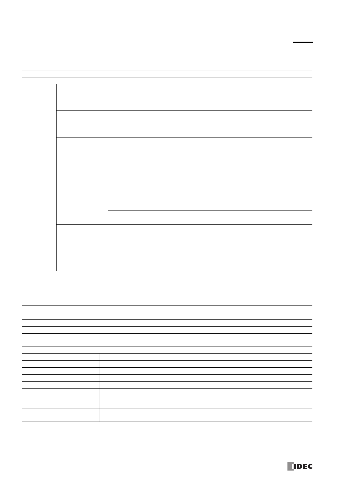
Name Used in This Manual Type Number, Part Code, or Official Name
FC6A Series MicroSmart FC6A Series MICROSmart
FC6A-C16R1AE, FC6A-C16R1CE, FC6A-C16K1CE, FC6A-C16P1CE,
All-in-One Type
CAN J1939 All-in-One Type
16-I/O type
24-I/O type
40-I/O type
CPU module
AC power type FC6A-C16R1AE, FC6A-C24R1AE, FC6A-C40R1AE, FC6A-C40R1AEJ
24V DC power type
DC power type
12V DC power type
Relay output type
Transistor sink output
Transistor output type
Expansion module Expansion I/O module, functional module
Expansion I/O module Input module, output module, mixed I/O module
Functional module Analog module, PID module
Analog module
Option module
Cartridge Analog cartridge, communication cartridge
WindLDR WindLDR application software
USB cable
type
Transistor protection
source output type
FC6A-C24R1AE, FC6A-C24R1CE, FC6A-C24K1CE, FC6A-C24P1CE,
FC6A-C40R1AE, FC6A-C40R1CE, FC6A-C40K1CE, FC6A-C40P1CE,
FC6A-C40R1DE, FC6A-C40R1DE, FC6A-C40K1DE, FC6A-C40P1DE
FC6A-C40R1AEJ, FC6A-C40R1CEJ, FC6A-C40K1CEJ, FC6A-C40P1CEJ,
FC6A-C40R1DEJ, FC6A-C40K1DEJ, FC6A-C40P1DEJ
The general term for the model with 16 I/O points
(FC6A-C16R1AE, FC6A-C16R1CE, FC6A-C16K1CE, FC6A-C16P1CE)
The general term for the model with 24 I/O points
(FC6A-C24R1AE, FC6A-C24R1CE, FC6A-C24K1CE, FC6A-C24P1CE)
The general term for the model with 40 I/O points
(FC6A-C40R1AE, FC6A-C40R1CE, FC6A-C40K1CE, FC6A-C40P1CE,
FC6A-C40R1DE, FC6A-C40R1DE, FC6A-C40K1DE, FC6A-C40P1DE,
FC6A-C40R1AEJ, FC6A-C40R1CEJ, FC6A-C40K1CEJ, FC6A-C40P1CEJ,
FC6A-C40R1DEJ, FC6A-C40K1DEJ, FC6A-C40P1DEJ)
FC6A-C16R1CE, FC6A-C24R1CE, FC6A-C40R1CE, FC6A-C16K1CE,
FC6A-C24K1CE, FC6A-C40K1CE, FC6A-C16P1CE, FC6A-C24P1CE,
FC6A-C40P1CE, FC6A-C40R1CEJ, FC6A-C40K1CEJ, FC6A-C40P1CEJ
FC6A-C40R1DE, FC6A-C40K1DE, FC6A-C40P1DE, FC6A-C40R1DEJ,
FC6A-C40K1DEJ, FC6A-C40P1DEJ
FC6A-C16R1AE, FC6A-C16R1CE, FC6A-C24R1AE, FC6A-C24R1CE,
FC6A-C40R1AE, FC6A-C40R1CE, FC6A-C40R1DE, FC6A-C40R1AEJ,
FC6A-C40R1CEJ, FC6A-C40R1DEJ
FC6A-C16K1CE, FC6A-C24K1CE, FC6A-C40K1CE, FC6A-C40K1DE,
FC6A-C40K1CEJ, FC6A-C40K1DEJ
FC6A-C16P1CE, FC6A-C24P1CE, FC6A-C40P1CE, FC6A-C40P1DE,
FC6A-C40P1CEJ, FC6A-C40P1DEJ
Analog input module, analog output module,
mixed analog I/O module
HMI module, expansion interface module,
analog cartridge, communication cartridge
USB maintenance cable (HG9Z-XCM42),
USB Mini-B extension cable (HG9Z-XCE21)
Name Used in this Manual WindLDR Operating Procedure
Function area settings Configuration tab > Function Area Settings group
Monitors Select Online > Monitor > Start Monitor.
PLC status Select Online > PLC > Status.
Communication settings Select Online > Communication > Set Up.
On the Configuration tab, in Function Area Settings, click Communication Ports, and in the
Modbus master request table
Application button
Preface-5 FC6A S
displayed Function Area Settings dialog box, for Communication Mode under Communication
Ports, select Modbus RTU Master or Modbus TCP Client
The button displayed on the left side of the menu bar. Click to display the menu with New, Save, and
Save As, recent projects, WindLDR Options, and Exit WindLDR.
ERIES MICROSMART ALL-IN-ONE TYPE USER’S MANUAL
FC9Y-B1722

T
ABLE OF
C
HAPTER
C
HAPTER
1: General Information
2: Product Specifications
C
ONTENTS
Safety Precautions............................................................................................................................. Preface-1
About This Manual............................................................................................................................. Preface-2
Related Manuals................................................................................................................................ Preface-4
Names and Abbreviations Used in this Manual ..................................................................................... Preface-5
About the FC6A Series MicroSmart................................................................................................................ 1-1
Features ..................................................................................................................................................... 1-7
Special Functions......................................................................................................................................... 1-8
Communication Functions .......................................................................................................................... 1-11
Maintenance Communication...................................................................................................................... 1-13
User Communication.................................................................................................................................. 1-14
Modbus Communication ............................................................................................................................. 1-14
Data Link System ...................................................................................................................................... 1-15
Ethernet Communication............................................................................................................................ 1-16
Operator Interface Connectivity .................................................................................................................. 1-17
Using J1939 Communication ...................................................................................................................... 1-17
Normal Operating Conditions........................................................................................................................ 2-1
CPU Module ................................................................................................................................................ 2-2
Expansion I/O Modules .............................................................................................................................. 2-37
Functional module ..................................................................................................................................... 2-63
Option module .......................................................................................................................................... 2-85
Dimensions ............................................................................................................................................... 2-97
C
HAPTER
C
HAPTER
3: Installation and Wiring
Installation Location .................................................................................................................................... 3-1
Assembly Methods....................................................................................................................................... 3-4
Mounting on DIN Rail .................................................................................................................................. 3-9
Input/Output Wiring .................................................................................................................................. 3-14
Power Supply and Power Supply Wiring ...................................................................................................... 3-16
Using the Ports ......................................................................................................................................... 3-19
Using an SD Memory Card ......................................................................................................................... 3-24
Replacing the Backup Battery ..................................................................................................................... 3-27
Connection Restrictions for Expansion Modules and Option Modules.............................................................. 3-29
Terminal Connection.................................................................................................................................. 3-33
Wiring the CAN J1939 Bus ......................................................................................................................... 3-37
4: Operation Basics
Start WindLDR ............................................................................................................................................ 4-1
PLC Selection ..............................................................................................................................................4-2
Create Program...........................................................................................................................................4-3
Save Project................................................................................................................................................ 4-8
Simulate Operation ...................................................................................................................................... 4-9
Download Program .................................................................................................................................... 4-10
Monitor Operation ..................................................................................................................................... 4-12
Exit WindLDR ............................................................................................................................................ 4-12
Checking the WindLDR Version Number ...................................................................................................... 4-13
Ladder Program Operation ......................................................................................................................... 4-14
Start/Stop Operation.................................................................................................................................. 4-15
C
HAPTER
5: Functions and Settings
Function List ............................................................................................................................................... 5-1
Function Area Settings ................................................................................................................................. 5-3
Stop Input and Reset Input .......................................................................................................................... 5-5
Run/Stop Selection at Keep Data Error.......................................................................................................... 5-7
Run/Stop Selection at Power Up ................................................................................................................... 5-8
Function Switch Configuration ...................................................................................................................... 5-9
Memory Backup ........................................................................................................................................ 5-11
FC6A S
ERIES MICROSMART ALL-IN-ONE TYPE USER’S MANUAL
FC9Y-B1722 Preface-6

T
ABLE OF CONTENTS
C
HAPTER
6: Devices
High-Speed Counter ...................................................................................................................................5-13
Catch Input ...............................................................................................................................................5-31
Interrupt Input ..........................................................................................................................................5-33
Frequency Measurement ............................................................................................................................5-35
Input Filter ................................................................................................................................................5-37
Analog Voltage Input .................................................................................................................................5-39
Analog Potentiometer.................................................................................................................................5-41
Timer Interrupt..........................................................................................................................................5-43
Forced I/O function....................................................................................................................................5-45
External Memory Devices............................................................................................................................5-48
32-bit Data Storage Setting ........................................................................................................................5-49
User Program Protection.............................................................................................................................5-51
Watchdog Timer Setting .............................................................................................................................5-53
Constant Scan Time ...................................................................................................................................5-54
Daylight Savings Time ................................................................................................................................5-55
Clock Function ...........................................................................................................................................5-56
Battery Monitor..........................................................................................................................................5-59
USB Boot...................................................................................................................................................5-60
User Program Capacity ...............................................................................................................................5-62
Online Edit ................................................................................................................................................5-63
Device Addresses ........................................................................................................................................ 6-1
Special Internal Relay.................................................................................................................................. 6-3
Special Data Register .................................................................................................................................6-13
C
HAPTER
C
HAPTER
C
HAPTER
7: HMI Function
HMI Function Overview ............................................................................................................................... 7-1
LCD Settings............................................................................................................................................... 7-3
About the Menu Screen ............................................................................................................................... 7-5
Basic Operations ......................................................................................................................................... 7-6
Switching run/stop ...................................................................................................................................... 7-9
Editing Programs .......................................................................................................................................7-10
FC6A Series MicroSmart Environment Settings .............................................................................................7-12
Monitoring the FC6A Series MicroSmart .......................................................................................................7-32
Checking/Clearing Error Information............................................................................................................7-37
Displaying Arbitrary Messages .....................................................................................................................7-39
Maintaining the SD Memory Card ................................................................................................................7-40
Reading and Writing Recipe Files ................................................................................................................7-42
Uploading/Downloading the User Program ...................................................................................................7-44
System Menu Hierarchy Diagram ................................................................................................................7-46
Communication Functions ...........................................................................................................................7-47
8: Instructions Reference
Basic Instruction List ................................................................................................................................... 8-1
Advanced Instruction List ............................................................................................................................ 8-3
9: Functional Modules
Analog Module............................................................................................................................................ 9-1
Analog Module Overview ............................................................................................................................. 9-1
Analog Module Parameter Settings ............................................................................................................... 9-3
Device Allocation .......................................................................................................................................9-13
PID Module ...............................................................................................................................................9-19
C
HAPTER
Preface-7 FC6A S
10: Analog Cartridge
Analog Cartridge Overview .........................................................................................................................10-1
Analog Cartridge Specifications ...................................................................................................................10-2
Analog Parameter Settings..........................................................................................................................10-4
ERIES MICROSMART ALL-IN-ONE TYPE USER’S MANUAL
FC9Y-B1722

C
HAPTER
C
HAPTER
C
HAPTER
A
PPENDIX
11: SD Memory Card
SD Memory Card Overview......................................................................................................................... 11-1
Save Log Data........................................................................................................................................... 11-6
Recipe Function......................................................................................................................................... 11-7
Downloads and Uploads using the SD Memory Card ................................................................................... 11-20
SD Memory Card Maintenance with Data File Manager ............................................................................... 11-38
12: Expansion Module and Cartridge Settings
Expansion Module and Cartridge Settings Overview ..................................................................................... 12-1
Basic Module Configuration Editor Operations .............................................................................................. 12-3
13: Troubleshooting
Reading Error Data .................................................................................................................................... 13-1
Special Data Registers for Error Information ................................................................................................ 13-3
General Error Codes .................................................................................................................................. 13-3
FC6A Series MicroSmart Operating Status, Output, and ERR LED during Errors .............................................. 13-4
Error Causes and Actions ........................................................................................................................... 13-4
User Program Execution Error .................................................................................................................... 13-6
Troubleshooting Diagrams ......................................................................................................................... 13-7
Type List.....................................................................................................................................................A-1
System Software .........................................................................................................................................A-6
USB Driver Installation Procedure .................................................................................................................A-9
Fonts........................................................................................................................................................ A-11
Cables ...................................................................................................................................................... A-13
HMI Screen Transition Diagram .................................................................................................................. A-15
T
ABLE OF CONTENTS
I
NDEX
FC6A S
ERIES MICROSMART ALL-IN-ONE TYPE USER’S MANUAL
FC9Y-B1722 Preface-8

T
ABLE OF CONTENTS
Preface-9 FC6A S
ERIES MICROSMART ALL-IN-ONE TYPE USER’S MANUAL
FC9Y-B1722

1: G
FC6A - C 40 R 1 A E J
CAN J1939 function
J: CAN J1939 function
None: No CAN J1939 function
Ethernet port
E: Ethernet port
None: No Ethernet port
Power supply
A: AC power type
C: 24V DC power type
D: 12V DC power type
Terminal specification
1: Pluggable terminal block
Output type
R: Relay output
K: Transistor sink output
P: Transistor protection source output
I/O points
16: 16 I/O points
24: 24 I/O points
40: 40 I/O points
Module type
C: All-in-One Type
ENERAL INFORMATION
Introduction
This chapter describes FC6A Series MicroSmart functions and system configuration examples.
About the FC6A Series MicroSmart
The FC6A Series MicroSmart is a small, All-in-One Type programmable controller with excellent expandability and a variety of
communication functions. The CPU modules are equipped with 16-, 24-, and 40-I/Os and support either 100 to 240V AC, 24V DC,
or 12V DC power supplies.
Expansion I/O modules, analog cartridges, communication cartridges, HMI modules, and other modules can be connected to the
CPU module. Inputs, outputs, and communication ports can be expanded according to application.
The FC6A Series MicroSmart can also be linked to various types of external devices with communication functions that include
maintenance communication, user communication, and Modbus communication. The FC6A Series MicroSmart is also equipped
with functions for high-speed counters, pulses, flow calculation, and data logging functions.
Programs used on the FC6A Series MicroSmart are created with WindLDR, easy-to-use, Windows-compatible ladder programming
software. This ladder programming software also supports the FC4A Series and the FC5A Series, so you can use your existing
ladder program resources.
Type Numbers
The notation for FC6A Series MicroSmart part numbers is as follows.
CPU module
Note: For details on the product specifications, see "Product Specifications" on page 2-1.
FC6A S
ERIES MICROSMART ALL-IN-ONE TYPE USER’S MANUAL
FC9Y-B1722 1-1

1: G
FC6A -
M08BR1
Output type
R: Relay output (Mixed I/O module only)
K: Transistor sink output
P: Transistor protection source output
None: No output
Input type
A1: 120V AC
B: 24V DC
None: No input
Terminal specification
1: Pluggable terminal block
3: MIL connector
I/O points
08: 8 I/O points
16: 16 I/O points
24: 24 I/O points
32: 32 I/O points
Module type
N: Input module
R: Output module (Relay output)
T: Output module (Transistor output)
M: Mixed I/O module
ENERAL INFORMATION
HMI module
FC6A -
Expansion I/O module
PH 1
Interface specification
1: Communication connector
Module type
PH: HMI module
Analog module
FC6A -
1-2 FC6A S
J4CN1
ERIES MICROSMART ALL-IN-ONE TYPE USER’S MANUAL
Terminal specification
1: Pluggable terminal block
Input type
None: Voltage/current input
N: Voltage/current/resistance temperature detector input
U: Thermistor/thermocouple input
Maximum resolution
A: 12 bits
C: 16 bits
I/O points
2: 2 I/O points
4: 4 I/O points
8: 8 I/O points
03: 3 I/O points
06: 6 I/O points
Module type
J: Analog input module
K: Analog output module
L: Mixed analog I/O module
FC9Y-B1722

PID module
FC6A -
PK2A V
Input type (Analog cartridge only)
None: Voltage/current input
P: Resistance temperature detector/thermocouple input
I/O points (For an analog cartridge)
2: 2 I/O points
Maximum resolution (Analog cartridge only)
A: 12 bits
C: 16 bits
Output type (Analog cartridge only)
V: Voltage output
W: Current output
Module type
PJ: Analog input cartridge
PK : Analog output cartridge
FC6A -
PC1
Communication/terminal specifications (for a communication cartridge)
1: RS232C communication/terminal block
3: RS485 communication/terminal block
Module type
PC : Communication cartridge
1: G
ENERAL INFORMATION
FC6A -
Expansion interface module
FC6A -
Analog cartridge
F2MR1
EXM 2
Terminal specification
1: Pluggable terminal block
Output type
None: Voltage/current input
R: Relay output
Input type
M: Multi input
Control loop points
2: 2 points
Module type
F: PID module
Module configuration
2: Integrated
Module type
EXM: Expansion interface module
Communication cartridge
FC6A S
ERIES MICROSMART ALL-IN-ONE TYPE USER’S MANUAL
FC9Y-B1722 1-3

1: G
FC9Z -
H0 A2050
Input type
A: Shielded straight cable
B: Non-shielded straight cable
Number of pins
20: 20
Cable length
050: 0.5 m
100: 1 m
200: 2 m
300: 3 m
Cable classification
H: Flat cable
ENERAL INFORMATION
Connector
FC6A -
PM 08PN05TA
Quantity per pack
02: 2
05: 5
Sale configuration
PN: 1 pack
Number of pins
03: 3
05: 5
08: 8
09: 9
10: 10
11: 11
12: 12
13: 13
17: 17
Terminal specification
A: 5.08 mm pitch, screw connection
B: 5.08 mm pitch, front screw connection
C: 3.81 mm pitch, front connection
D: 5.08 mm pitch, screw connection
(dedicated for use with the CPU module
power supply terminal)
E: Front screw connection with screw flange
(dedicated for use with CAN communication)
None: MIL connector
Wiring connection configuration
T: Screw fastened type
(no silk printing: for FC6A)
S: Spring clamp type
(no silk printing: for FC6A)
TS: Screw fastened type
(with source output silk printing: for FC4A/FC5A)
TK: Screw fastened type
(with sink output silk printing: for FC4A/FC5A)
C: MIL connector
Product classification
PM: Connector
Cable
1-4 FC6A S
ERIES MICROSMART ALL-IN-ONE TYPE USER’S MANUAL
FC9Y-B1722

Battery holder
FC6A -
BH N021P
Sale configuration
PN : 1 pack
Quantity per pack
02: 2
05: 5
Type 2
1: Standard product
Product classification
BH: Battery holder
1: G
ENERAL INFORMATION
FC6A S
ERIES MICROSMART ALL-IN-ONE TYPE USER’S MANUAL
FC9Y-B1722 1-5
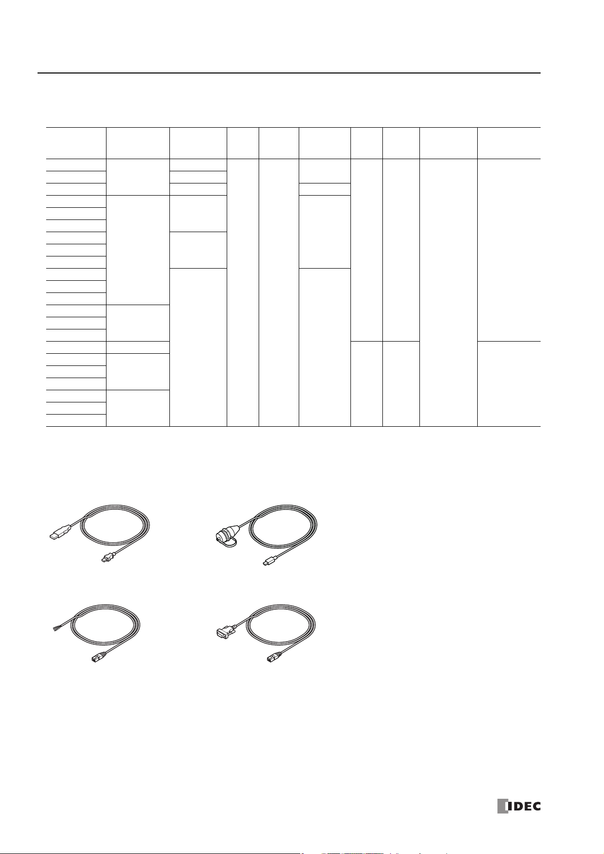
1: G
USB Maintenance Cable
HG9Z-XCM42
Panel Mount USB Extension Cable
HG9Z-XCE21
External Device/O/I Communication Cable
FC6A-KC1C
O/I Communication Cable
FC6A-KC2C
ENERAL INFORMATION
CPU Module Type Numbers and Functions List
Type numbers and functions
Type Number Power Supply
FC6A-C16R1AE
FC6A-C24R1AE 24 (504)
FC6A-C40R1AE 40 (520) 2
FC6A-C16R1CE
FC6A-C16K1CE
FC6A-C16P1CE
FC6A-C24R1CE
FC6A-C24P1CE
FC6A-C40R1CE
FC6A-C40K1CE
FC6A-C40P1CE
FC6A-C40R1DE
FC6A-C40P1DE
FC6A-C40R1AEJ 100 to 240V AC
FC6A-C40R1CEJ
FC6A-C40P1CEJ
FC6A-C40R1DEJ
FC6A-C40P1DEJ
*1 The value in parentheses ( ) is the number of inputs and outputs when using the expansion interface module and the maximum number of
expansion modules are connected.
100 to 240V AC
24V DC
12V DCFC6A-C40K1DE
24V DCFC6A-C40K1CEJ
12V DCFC6A-C40K1DEJ
Inputs and
Outputs
16 (496)
16 (496)
24 (504)FC6A-C24K1CE
40 (520) 2
*1
USB
Ethernet
Port
Port 1
Yes Yes
Number of
Cartridge
Slots
1
1
CAN
Port
Serial
Port 1
—Yes
Yes — —
SD Memory
Card Slot
Yes
Analog Input/
Volume
Yes (1 ea ch )
Options
1-6 FC6A S
ERIES MICROSMART ALL-IN-ONE TYPE USER’S MANUAL
FC9Y-B1722

1: G
ENERAL INFORMATION
Features
This section describes the features of the FC6A Series MicroSmart.
High-speed Instruction Processing
The FC6A Series MicroSmart is capable of high-speed arithmetic processing of basic instructions (LOD) in 0.042 μs and advanced
instructions (MOV) in 0.120 μs. This improves real time performance during program execution.
Abundant Program Capacity
The program capacity of the FC6A Series MicroSmart is a maximum of 384,000 bytes (approximately 48,000 steps) for the All-inOne Type. The CAN J1939 All-in-One Type also has a maximum of 640,000 bytes (approximately 80,000 steps). The FC6A Series
MicroSmart can be incorporated into a wide variety of systems thanks to the large program capacity.
If the user program Online Edit function is used, the program capacity is restricted to 72,000 bytes (approximately 9,000 steps).
Online Edit
User programs can be overwritten (run-time programming) and tests can be written while the ladder program is being executed.
Various Communication Functions
The FC6A Series MicroSmart supports maintenance communication, user communication, Modbus communication, and data link
communication. It also supports the SNTP function, web server function, and send email function using Ethernet to meet demands
for remote monitoring and maintenance. The FC6A Series MicroSmart is equipped with RS232C, RS485, an Ethernet port, and a
USB port as communication interfaces, which allows it to be connected to various devices including computers, operator interfaces,
and printers. The CAN J1939 All-in-One Type is also equipped with a CAN port that supports J1939 communication.
SD Memory Card
The FC6A Series MicroSmart is equipped with an SD memory card slot. The log data of device values, configuration data, user
programs, and system software can be saved to a commercially available SD memory card (32 GB maximum).
Powerful HMI Functions
Device values can be checked and modified on the HMI module's LCD. The LCD can also display the current time, bar charts,
messages, and text. The HMI module is equipped with fonts in the following nine languages and can display messages and text in
those languages. The HMI module can be operated using the operation buttons. Operations such as switching what is shown on
the LCD can be performed using the operation buttons.
Setting Name Character Set Supported Languages
European ISO 8859-1 (Latin-1) English, German, Italian, Spanish, Dutch (Note), French (Note)
Japanese Shift-JIS Japanese (level 1)
Chinese GB2312 Chinese (simplified)
Cyrillic ANSI 1251 Russian
Note: Some of the characters cannot be input.
FC6A S
ERIES MICROSMART ALL-IN-ONE TYPE USER’S MANUAL
FC9Y-B1722 1-7

1: G
ENERAL INFORMATION
Special Functions
This section describes the functions of the FC6A Series MicroSmart.
I/O Related Functions
Catch Input
The catch input receives short input pulses from sensors without regard to the scan time. A maximum of 6 catch inputs can be
used.
Input Filter
The input filter can be adjusted, according to the width of input signals, to reject input noises. Selectable input filter values to pass
input signals are 0 ms, and 3 through 15 ms in 1 ms increments. The input filter rejects inputs shorter than the selected input filter
value minus 2 ms. This function is useful for eliminating input noises and bounce in limit switches.
Interrupt Input
The interrupt input can be used to call an interrupt program to respond to an external input that requires a response faster than
the ladder program scan time. A maximum of six interrupt inputs can be used.
Stop and Reset Inputs
The stop input is a function to stop ladder program execution. The reset input is a function to stop ladder program operation and
clear device values. Any input terminal on the FC6A Series MicroSmart can be designated as a stop or reset input to control the
FC6A Series MicroSmart operation.
Built-in Analog Input Function
This function acquires 0 to 10V DC analog input as a 0 to 1,000 digital value in a special data register. There is one built-in analog
input.
Analog Potentiometer Function
This function acquires volume input as a 0 to 1,000 digital value in a special data register according to the position of the volume.
There is one analog potentiometer.
Forced I/O
The inputs and outputs of the FC6A Series MicroSmart can be forced on or off. This function can be used to check the I/O wiring
or the user program operation.
1-8 FC6A S
ERIES MICROSMART ALL-IN-ONE TYPE USER’S MANUAL
FC9Y-B1722
1: G
Pulse Motor
High-speed Pulse Input
Two-phase Pulses
Rotary
Encoder
FC6A Series MicroSmart
Steady pulse frequency
Initial pulse frequency
ENERAL INFORMATION
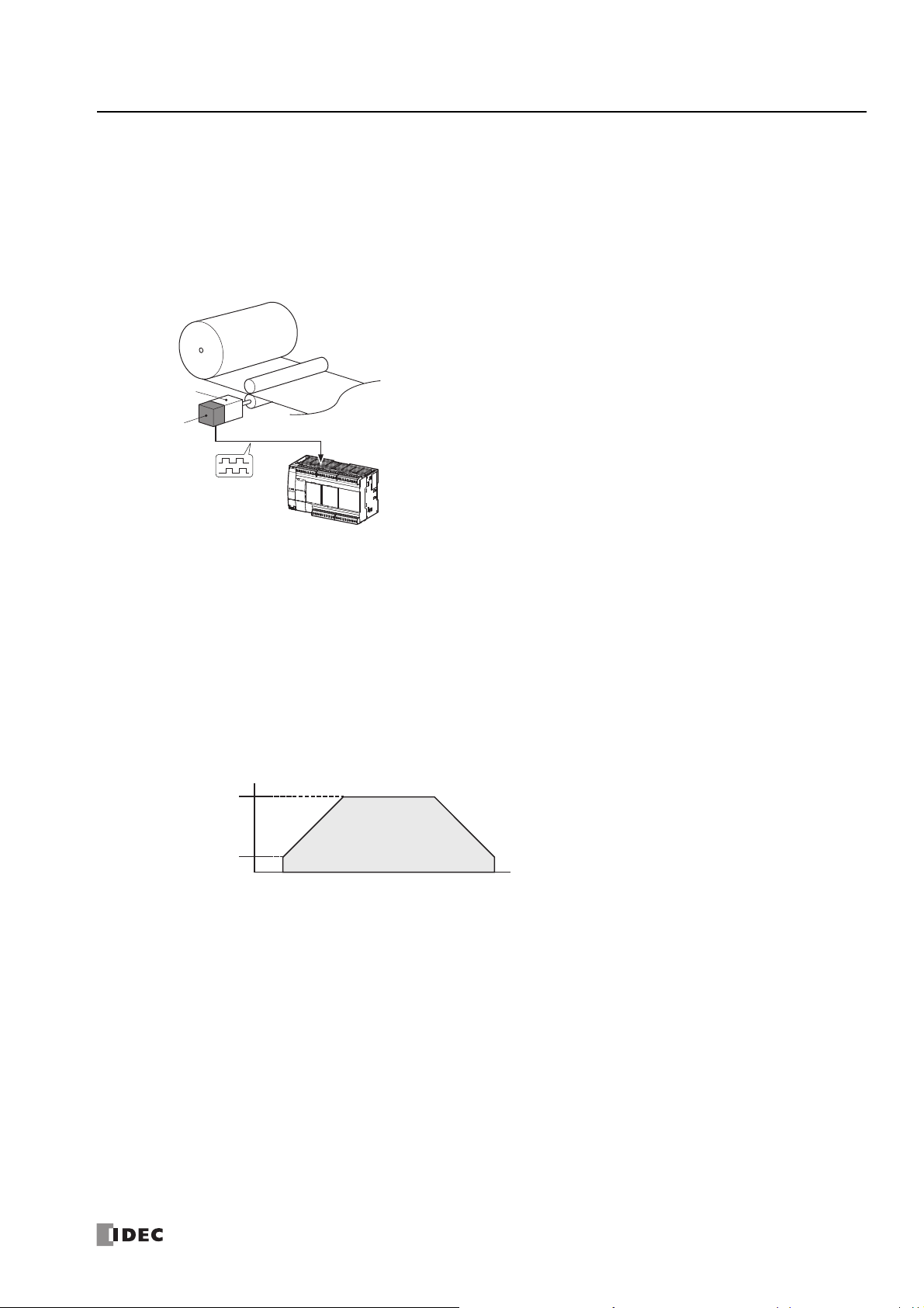
High-speed I/O Functions
High-speed Counter
This function counts high-speed pulse inputs that cannot be measured in normal user program processing.
Use this function for applications such as positioning control with a rotary encoder or motor control. The FC6A Series MicroSmart
can use single-phase high-speed counters and two-phase high-speed counters. A maximum of six single-phase high-speed
counters and a maximum of two two-phase high-speed counters can be used simultaneously.
Example: Controlling a motor by counting two-phase pulse input with a high-speed counter
Positioning Control
The FC6A Series MicroSmart can perform positioning control with pulse outputs. The FC6A Series MicroSmart features the PULS
instructions that can generate pulse outputs with configured frequency at the fixed pulse width ratio, JOG instructions, pulse-width
modulation (PWM) instructions that can generate pulse outputs with configured pulse width ratio at a fixed frequency, RAMP
instructions for trapezoidal control, ZRN instructions for zero return operation, and ARAMP instructions that can generate pulse
outputs according to a table in which the changes of the frequency are configured.
The FC6A Series MicroSmart also manages coordinates internally and can increment or decrement coordinates according to the
number of pulses that were output and the direction.
After confirming the origin using the ZRN instruction, the target position can also be specified by absolute position.
Example: Pulse output by the RAMP instruction
Frequency Measurement
This function measures the frequency of pulses input to an input terminal. The frequencies of a maximum of six inputs can be
measured.
FC6A S
ERIES MICROSMART ALL-IN-ONE TYPE USER’S MANUAL
FC9Y-B1722 1-9

1: G
ENERAL INFORMATION
Convenient Functions
Calendar/Clock
The FC6A Series MicroSmart features a real-time clock on-board. Using the calendar and clock function, the FC6A Series
MicroSmart can operate according to the current date and time. These functions can be used to control a time schedule for lighting
or air conditioning equipments.
The FC6A Series MicroSmart also supports daylight savings time and the date and time of the switch can be freely set to allow for
use in any region.
User Program Read/Write Protection
The user program in the FC6A Series MicroSmart can be protected against reading and/or writing by including a password in the
user program. This function is effective for security of user programs.
“Keep” or “Clear” Designation of FC6A Series MicroSmart Data
This function specifies whether or not to keep FC6A Series MicroSmart device values when there is a power interruption.
Devices that can be specified as kept are internal relays, shift registers, counter current values, and data registers.
RUN/STOP Selection at Startup when “Keep” Data is Lost
When the backup battery is dead, all data to be kept are lost. The user can select whether the FC6A Series MicroSmart starts to
run or not to prevent undesirable operation at the startup.
Log Data
Device values of the FC6A Series MicroSmart can be saved as CSV files on the SD memory card. The DLOG instruction saves device
values to the SD memory card. The TRACE instruction accumulates device values at each scan and saves them to the SD memory
card at the desired timing.
Constant Scan Time
The variations in scan time that occur when the user program is running can be made constant.
Timer Interrupt
The timer interrupt can be used to call an interrupt program at a predetermined interval of time without being affected by the scan
time.
Script Function
This function allows programming complicated processing with conditional branching, logical operations, arithmetic operations,
and functions as text. Devices can also be read and written. Execute scripts using the SCRPT instruction.
Recipe Function
This function allows the values of device settings to be written to a CSV file to create a recipe file. The values of device settings can
be read from a recipe file and reflected in the FC6A Series MicroSmart devices.
Applicable devices are word devices such as timers, counters, and data registers.
SNTP Function
The current time can be acquired from an SNTP server.
USB Boot Function
This function starts the FC6A Series MicroSmart with power supplied from the USB cable.
This allows the user program and system software to be updated.
During USB boot, USB communication and the SD memory card can be used.
PID Control Function
PID control performs temperature control and other types of control using a PID (proportional-integral-derivative) calculation
algorithm. The FC6A Series MicroSmart can perform PID control by automatically calculating the optimal PID value using the auto
tuning function.
Function Switch
The FC6A Series MicroSmart is equipped with a function switch which can be used to run or stop the user program. The button can
be used for any desired purpose by using the on/off status of the function switch stored in the special internal relay.
1-10 FC6A S
ERIES MICROSMART ALL-IN-ONE TYPE USER’S MANUAL
FC9Y-B1722

1: G
ENERAL INFORMATION
Communication Functions
The FC6A Series MicroSmart can perform RS232C and RS485 communication using serial port 1. The communication ports can be
expanded by using communication cartridges to allow for multiple instances of RS232C and RS485 communication. The Ethernet
port is standard equipment to enable communication using Ethernet. The CAN J1939 All-in-One Type is equipped with a CAN port
to enable J1939 communication.
Communication Functions
Maintenance communication enables you to check the operating status and I/O status of the FC6A Series
Maintenance Communication
User Communication
Modbus Communication
Data Link Communication
J1939 Communication
For details on communication functions, see the "FC6A Series MicroSmart All-in-One Type Communication Manual".
Communication Ports
MicroSmart, to display and change device values, and download and upload user programs using a
computer or operator interface.
Data can be sent and received by creating commands for external devices (computers, printers, barcode
readers, and other devices).
Data can be sent and received between communication device that conforms to the Modbus protocol and
the FC6A Series MicroSmart.
Data can be sent and received between a master station and slave stations by connecting a maximum of
31 MicroSmarts (slave station) to a MicroSmart (master station).
The CAN J1939 All-in-One Type can send and receive data with communication device that conforms to
the SAE-J1939 standard.
USB Port
Ethernet Port 1
HMI-Ethernet Port
Serial Port 1
Communication Cartridge
(option module)
CAN port The CAN J1939 All-in-One Type is capable of J1939 communication using this port.
Maintenance communication can be performed by connecting the FC6A Series MicroSmart to a computer
using this port.
The FC6A Series MicroSmart can communicate with Ethernet communication-compatible external devices
such as computers and operator interfaces using this port. Maintenance communication, user
communication, and Modbus TCP communication are possible.
This port connects the HMI module to the CPU module and allows the HMI module to be used. The FC6A
Series MicroSmart can communicate with Ethernet communication-compatible external devices such as
computers and operator interfaces using this port. Maintenance communication is possible.
The FC6A Series MicroSmart can communicate with RS232C/RS485 communication-compatible external
devices such as computers, operator interfaces, and printers using this port. Maintenance communication,
user communication, Modbus RTU communication, and data link communication are possible.
The FC6A Series MicroSmart is capable of maintenance communication, user communication, Modbus
RTU communication, and data link communication using this port.
FC6A S
ERIES MICROSMART ALL-IN-ONE TYPE USER’S MANUAL
FC9Y-B1722 1-11

1: G
ENERAL INFORMATION
Communication Ports, Serial Port 1, Communication Cartridge 1 and 2 Corresponding Table
The communication ports that are used in serial communication support the following communication interfaces.
Type No.
Port 1 Port 2 Port 3
Serial Port
FC6A-C16R1AE
FC6A-C16R1CE
FC6A-C16K1CE
FC6A-C16P1CE
FC6A-C24R1AE
No supported communication
interface
FC6A-C24R1CE
FC6A-C24K1CE
FC6A-C24P1CE
Serial Port 1
*1
FC6A-C40R1AE
FC6A-C40R1CE
FC6A-C40K1CE
FC6A-C40P1CE
Cartridge Slot 1
communication cartridge*2
*4
FC6A-C40R1DE
FC6A-C40K1DE
FC6A-C40P1DE
FC6A-C40R1AEJ
Cartridge Slot 2
communication cartridge*3
*4
FC6A-C40R1CEJ
FC6A-C40K1CEJ
FC6A-C40P1CEJ
FC6A-C40R1DEJ
No supported communication
interface
FC6A-C40K1DEJ
FC6A-C40P1DEJ
*1 Can be used as port 1 for RS232C communication or RS485 communication.
To use, configure the interface under Communication Port in Function Area Settings.
*2 Can be used as port 2 by installing the RS232C communication cartridge (FC6A-PC1) or the RS485 communication cartridge (FC6A-PC3).
*3 Can be used as port 3 by installing the RS232C communication cartridge (FC6A-PC1) or the RS485 communication cartridge (FC6A-PC3).
*4 Cannot be set to "Data Bits: 7 bits" and "Parity: None".
Notes:
• For the locations of serial port 1, cartridge slot 1, and cartridge slot 2, see "Part Names and Functions" on page 2-2.
• For serial port 1 wiring, see "Other Inputs and Ports" on page 2-35. For communication cartridge wiring, see "Terminal Arrangement and
Wiring Examples" on page 2-96.
1-12 FC6A S
ERIES MICROSMART ALL-IN-ONE TYPE USER’S MANUAL
FC9Y-B1722
1: G
FC6A Series MicroSmart
Windows Computer
USB Port
(USB 2.0 Mini-B Connector)
HG9Z-XCM42 USB Maintenance Cable
Type A Plug Mini-B Plug
USB Port
Windows Computer
FC6A Series MicroSmart FC6A Series MicroSmart FC6A Series MicroSmart
Ethernet Hub
Ethernet Port 1 Ethernet Port 1Ethernet Port 1
ENERAL INFORMATION
Maintenance Communication
The maintenance communication of the FC6A Series MicroSmart enables you to check the operating status and I/O status of the
FC6A Series MicroSmart, monitor and change device values, and download and upload user programs with the PLC programming
software WindLDR installed on a computer. For details on maintenance communication, see the "FC6A Series MicroSmart All-inOne Type Communication Manual".
Supported ports
*1
USB Port Serial Port 1
Yes Yes Yes Yes No
*1 Depending on the port that will be used, there are restrictions on the maintenance communication methods that can be used. For details on the
restrictions, see the "FC6A Series MicroSmart All-in-One Type Communication Manual".
*2 Only maintenance communication can be used with the HMI-Ethernet port.
Ethernet Port 1 and
HMI-Ethernet Port
*2
Communication
Cartridge
CAN Port
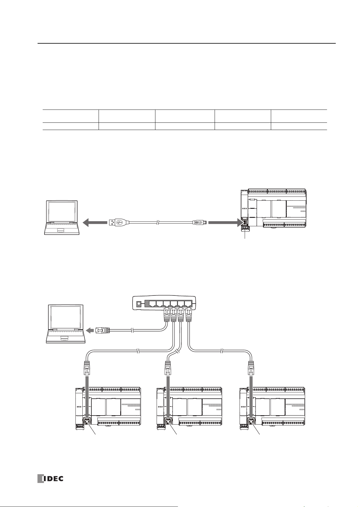
■ 1:1 Maintenance Communication System
This example shows a 1:1 maintenance communication system in which a FC6A Series MicroSmart and a computer are connected
with USB. The USB maintenance cable (HG9Z-XCM42) is used.
■ 1:N Maintenance Communication System
This example shows a 1:N maintenance communication system in which three FC6A Series MicroSmart and a computer are
connected over Ethernet. The Ethernet cables are connected to the Ethernet port 1 of three FC6A Series MicroSmart, and those
FC6A Series MicroSmart are connected to the computer via an Ethernet hub.
FC6A S
ERIES MICROSMART ALL-IN-ONE TYPE USER’S MANUAL
FC9Y-B1722 1-13
1: G
Serial Port 1
(Port 1)
Barcode Reader
FC6A Series MicroSmart
INVERTER
RUN
RVS
ALM
COM
Temperature Controller
Inverter
Serial Port 1
(Port 1)
FC6A Series MicroSmart
ENERAL INFORMATION
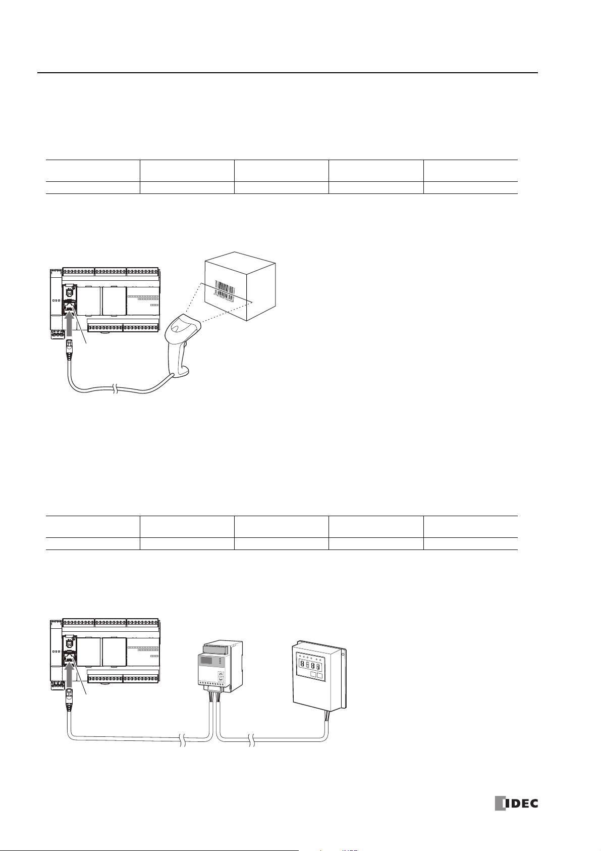
User Communication
The user communication of the FC6A Series MicroSmart enables you to control external devices such as computers, printers, and
barcode readers. For details on user communication, see the "FC6A Series MicroSmart All-in-One Type Communication Manual".
Supported ports
USB Port Serial Port 1 Ethernet Port 1
Communication
Cartridge
CAN Port
No Yes Yes Yes No
■ User Communication Using Serial Port 1
This example shows a system in which a FC6A Series MicroSmart receives the data read by a barcode reader. A barcode reader is
connected to port 1 of the FC6A Series MicroSmart.
Modbus Communication
The FC6A Series MicroSmart is compliant with Modbus RTU protocol and can be used as either a Modbus communication master or
slave. With Modbus communication, the FC6A Series MicroSmart can monitor and modify the data of inverters and temperature
controllers.
For details on Modbus communication, see the "FC6A Series MicroSmart All-in-One Type Communication Manual".
Supported ports
USB Port Serial Port 1 Ethernet Port 1
Communication
Cartridge
CAN Port
No Yes Yes Yes No
■ Modbus RTU Communication Using Serial Port 1
This example shows a system in which a FC6A Series MicroSmart is communicating with a temperature controller and an inverter
that support Modbus RTU. The A temperature controller is connected to port 1 of the FC6A Series MicroSmart.
1-14 FC6A S
ERIES MICROSMART ALL-IN-ONE TYPE USER’S MANUAL
FC9Y-B1722
1: G
FC6A Series MicroSmart
(Slave Station 1)
FC6A Series MicroSmart
(Slave Station 31)
Serial Port 1
(Port 1)
FC6A Series MicroSmart
(Master Station)
ENERAL INFORMATION
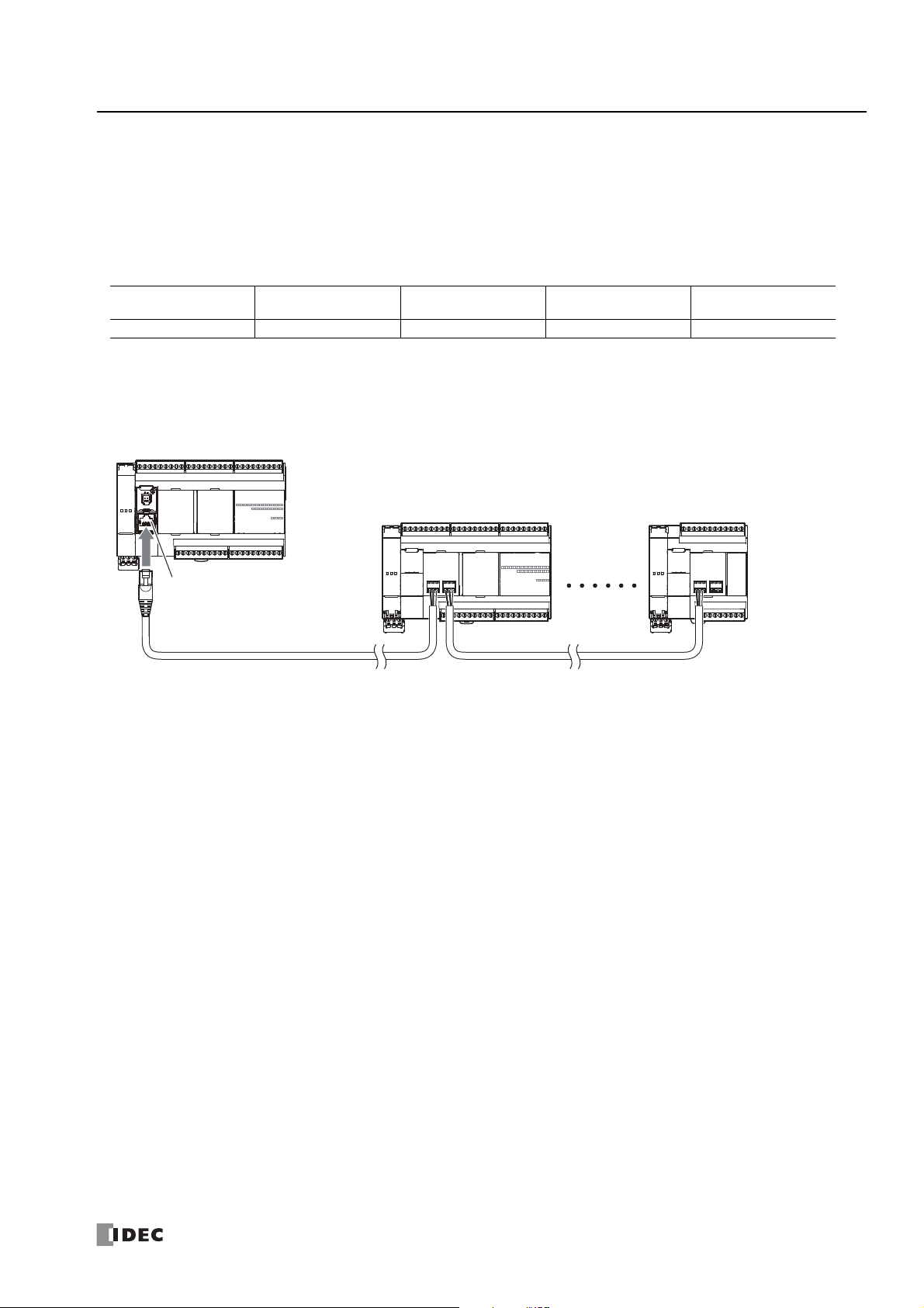
Data Link System
The FC6A Series MicroSmart supports data link communication, and it can share data between CPU modules using serial port 1
and cartridge slots. The FC6A Series MicroSmart can also share data with FC5A Series and FC4A Series CPU modules. Configure
the settings in WindLDR to enable distributed control of a maximum of 31 CPU modules.
For details about the data link communication, see the "FC6A Series MicroSmart All-in-One Type Communication Manual".
Supported ports
USB Port Serial Port 1 Ethernet Port 1
No Yes No Yes No
Communication
Cartridge
CAN Port
■ Data Link Communication Using Serial Port 1
This example shows communication between multiple CPU modules with the FC6A Series MicroSmart as the master station. A
slave station CPU module is connected to Serial Port 1 of the FC6A Series MicroSmart.
FC6A S
ERIES MICROSMART ALL-IN-ONE TYPE USER’S MANUAL
FC9Y-B1722 1-15
1: G
Ethernet Port 1
Operator Interface
Windows Computer
FC6A Series MicroSmart
Ethernet Hub Ethernet Hub
Ethernet
Barcode Reader
ENERAL INFORMATION
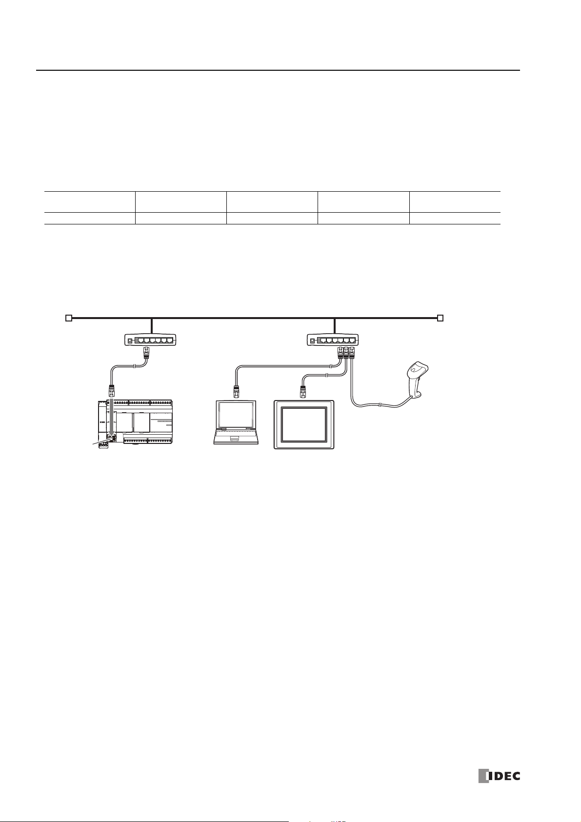
Ethernet Communication
The FC6A Series MicroSmart can be connected to the Ethernet network using Ethernet port 1 and communicate with network
devices over Ethernet.
The FC6A Series MicroSmart has eight TCP/IP connections that can be used for Ethernet communication functions. Each of these
connections can simultaneously be used for a different communication protocol. Each connection can be configured for
maintenance communication, user communication, or Modbus TCP communication.
Supported ports
USB Port Serial Port 1 Ethernet Port 1
No No Yes No No
Communication
Cartridge
CAN Port
■ Ethernet Communication Example
This example shows Ethernet communication between the FC6A Series MicroSmart equipped with Ethernet port 1, an operator
interface, and a computer. Among the three connections the FC6A Series MicroSmart has, Connection
1 is configured as
maintenance communication for the computer to communicate with the FC6A Series MicroSmart. Connection 2 is configured as
Modbus TCP server for the operator interface to communicate with the FC6A Series MicroSmart. Connection 3 communicates with
the barcode reader as user communication. Connection 4 to connection 8 are not used.
Notes:
• When accessing the FC6A Series MicroSmart over the Internet, adequate security measures for the network to prevent unauthorized access
are required. Be sure to consult your network administrator or Internet service provider. IDEC bears no responsibility for damages or
problems caused due to security in Ethernet communication.
• Restrict the access to FC6A Series MicroSmart with IP addresses and ports by using appropriate measures such as the firewall.
1-16 FC6A S
ERIES MICROSMART ALL-IN-ONE TYPE USER’S MANUAL
FC9Y-B1722
1: G
O/I Communication Cable: FC6A-KC2C
(D-sub 9-pin connector style, cable length: 5 m)
Operator Interface
FC6A Series MicroSmart
Serial Communication Port
(RS232C)
Serial Port 1
(Port 1)
Engine
FC6A Series MicroSmart
(CAN J1939 All-in-One Type)
CAN Port
CAN
ENERAL INFORMATION
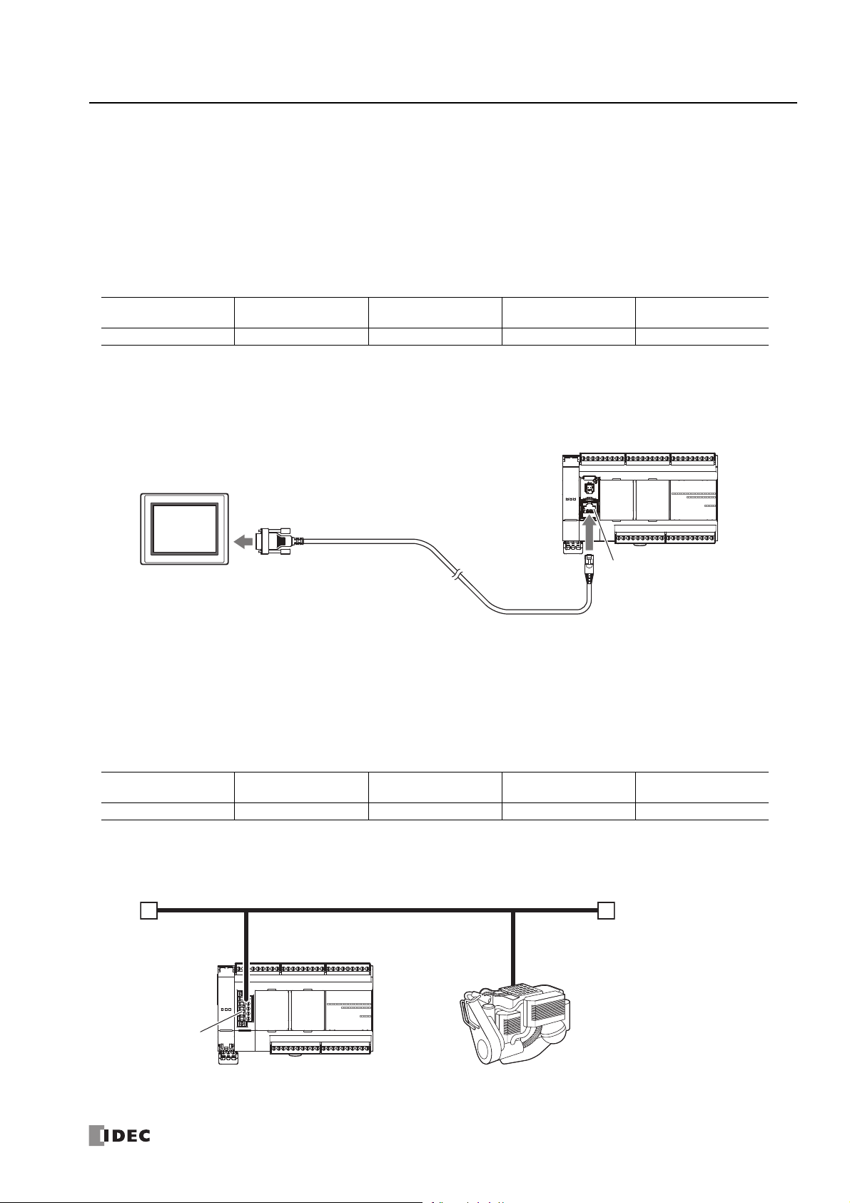
Operator Interface Connectivity
The FC6A Series MicroSmart can perform maintenance communication with IDEC operator interfaces using Ethernet port 1, serial
port 1, and communication cartridge. FC6A Series MicroSmart device values can be monitored and modified by the connected
operator interface. An Ethernet cable or an O/I communication cable
operator interface.
For details on the communication settings, see the "WindO/I-NV2 User's Manual", the "WindO/I-NV3 User's Manual", and the
"WindO/I-NV4 User's Manual".
Supported ports
*1
is used to connect the FC6A Series MicroSmart and the
USB Port Serial Port 1 Ethernet Port 1
No Yes Yes Yes No
Communication
Cartridge
CAN Port
■ 1:1 Maintenance Communication Example with an IDEC Operator Interface Using Serial Port 1
This example shows maintenance communication between the FC6A Series MicroSmart and an operator interface, as well as
monitoring and changing FC6A Series MicroSmart device values using the operator interface. An IDEC operator interface is
connected to serial port 1 of the FC6A Series MicroSmart.
*1 For details on O/I communication cables, see "Cables" on page A-13.
Using J1939 Communication
The CAN J1939 All-in-One Type can be connected to a J1939 communication network using the CAN port and it can communicate
with other J1939 communication-compatible devices. Messages that conform to the SAE J1939 standard can be sent and received.
For details on J1939 communication, see the "FC6A Series MicroSmart All-in-One Type Communication Manual".
Supported ports
■ CAN Port Usage Example
This example shows the FC6A Series MicroSmart communicating with a J1939-compatible engine. The CAN port of the CAN J1939
All-in-One Type is connected to the engine.
USB Port Serial Port 1 Ethernet Port 1
No No No No Yes
FC6A S
ERIES MICROSMART ALL-IN-ONE TYPE USER’S MANUAL
Communication
Cartridge
FC9Y-B1722 1-17
CAN Port

1: G
ENERAL INFORMATION
1-18 FC6A S
ERIES MICROSMART ALL-IN-ONE TYPE USER’S MANUAL
FC9Y-B1722

2: P
This chapter describes the part names and specifications of the modules that make up the FC6A Series MicroSmart.
Various types of modules are available for the FC6A Series MicroSmart, including CPU modules (All-in-One Type, CAN J1939 All-inOne Type), expansion I/O modules (input modules, output modules, mixed I/O modules), functional modules (analog modules,
PID modules), and option modules (expansion interface module, HMI module, analog cartridges, communication cartridges).
RODUCT
S
PECIFICATIONS
Normal Operating Conditions
The normal operating conditions common to the modules are as follows.
Ambient Operating Temperature -10 to+55°C
Ambient Storage Temperature -25 to+70°C (no freezing)
Relative Humidity 10 to 95%, no condensation
Storage Humidity 10 to 95%, no condensation
Pollution Degree 2 (IEC60664-1)
Degree of Protection IP20 (IEC60529)
Atmosphere No corrosive gas
Altitude or Air Pressure
Installation Location Inside cabinet
Device Class Open equipment
Overvoltage Category II
Vibration Resistance
Shock Resistance 147 m/s2 (15 G), 11 ms, XYZ, 3 axes, 6 directions, 3 times each (IEC 61131-2)
EMC Immunity IEC/EN61131-2, Zone B compatibility
*1 The HMI module (FC6A-PH1) is 0 to 55°C.
DIN Rail Mounted
Panel Mounted
1,013 to 795 hPa (0 to 2,000 m) during operation
1,013 to 701 hPa (0 to 3,000 m) during transport
5 to 8.4 Hz half amplitude 3.5 mm, 8.4 to 150 Hz, acceleration 9.8 m/s2 (1 G), each
direction XYZ, 2 hours (IEC/EN 61131-2)
*1
FC6A S
ERIES MICROSMART ALL-IN-ONE TYPE USER’S MANUAL
FC9Y-B1722 2-1

2: P
(23) Communication Connector
(24) Function Switch
(25) Analog Input
(2) Cartridge Slot 1
(22) SD Memory Card Slot
(21) USB Port
(20) Power Supply Terminals
(17) Ethernet Port 1
(19) LINK LED
(18) ACT LED
(16) Serial Port1
(15) Output Terminals
(4) Input Terminals
(1) Sensor Power Terminals
(Not used with DC power
supply types.)
(6) Expansion Connector
(5) Battery Holder
(26) Analog Potentiometer
(3) Cartridge Slot 2
Top
Right SideLeft Side
(7) Input LEDs [IN]
(8) Output LEDs [OUT]
(9) Power LED [PWR]
(10) Run LED [RUN]
(11) Error LED [ERR]
(12) SD Memory Card Status LED [SD]
(13) Battery Status LED [BAT]
(14) Status LED [STAT]
(29) Dummy Cartridges
(34) USB Port Cover
(33) Power Supply Terminals Cover
(31) Serial Port 1 Cover
(32) Ethernet Port 1 Cover
Right SideLeft Side
(35) Communication
Connector Protection Sticker
(30) Expansion Connector
Protection Sticker
(27) SD Memory Card Cover (28) Analog Port Cover
RODUCT SPECIFICATIONS
CPU Module
All-in-One Type
The All-in-One Type CPU module is available in two types: the All-in-One Type equipped with analog input and serial ports (RS232C/RS-485) and the CAN J1939 All-in-One Type equipped with a CAN port.
Part Names and Functions
■ All-in-One Type
Example: FC6A-C40R1AE
The content in brackets is the LED indicator name on the FC6A Series MicroSmart.
LED Indicators
16-I/O Type 24-I/O Type 40-I/O Type
01234567
(7)
IN
10
0123456
OUT
(8)
(9)
(14)
(13)(12)(11)(10)
01234567
(7)
01234567
(8)
IN
10 11 1213 1415
10 11
OUT
(9)
(14)
(13)(12)(11)(10)
01234567
10 11 1213 1415 16 17
01234567
(7)
20 21 2223 2425 26 27
10 11 1213 1415 16 17
OUT
(8)
(9)
IN
(14)
(13)(12)(11)(10)
PWR
RUN
ERRSDBAT
STAT
2-2 FC6A S
ERIES MICROSMART ALL-IN-ONE TYPE USER’S MANUAL
PWR
RUN
ERRSDBAT
PWR
RUN
ERRSDBAT
STAT
STAT
FC9Y-B1722

2: P
RODUCT SPECIFICATIONS
(1) Sensor power terminals (AC power type)
These terminals supply DC power (24V DC, 250 mA) for a sensor (can also be used as a power supply for inputs).
The DC power type does not use these terminals.
(2) Cartridge Slot 1
This slot is used for installing an analog cartridge or communication cartridge.
(3) Cartridge Slot 2 (40-I/O type only)
This slot is used for installing an analog cartridge or communication cartridge.
The 16-I/O and 24-I/O types do not have this slot.
(4) Input Terminals
These terminals connect input devices such as push buttons and limit switches. DC inputs are both sinks and sources.
(5) Battery Holder
This holder is for installing the backup battery.
(6) Expansion Connector
This connector is used to connect expansion modules.
(7) Input LEDs [IN]
These LEDs turn on when an input is on. The LED with the corresponding number turns on.
(8) Output LEDs [OUT]
These LEDs turn on when an output is on. The LED with the corresponding number turns on.
(9) Power LED [PWR]
This LED turns on when power is supplied to the CPU module.
(10) Run LED [RUN]
This LED turns on while the CPU module is running the user program.
This LED flashes when using certain functions while the user program is running.
LED Status
ON • While the CPU module is running the user program
Slow flashing (1 s cycle)
Quick flashing (100 ms cycle)
• While the CPU module is in USB boot
• When executing the forced I/O function while the user program is running
• When updating the user program or system software while the CPU module is in USB boot
• When executing the forced I/O function while the user program is stopped
(11) Error LED [ERR]
This LED turns on when an error occurs in the CPU module.
(12) SD Memory Card Status LED [SD]
This LED turns on or flashes when the SD memory card is being read or written.
LED Status
• When the SD memory card is not inserted
OFF
ON • The standby state where the SD memory card can be written or read
Slow flashing (1 s cycle)
Quick flashing (100 ms cycle) • Reading or writing the SD memory card
• When an unsupported or unformatted SD memory card was inserted
• When access to the SD memory card was stopped by the SD memory card access stop flag (M8076)
• When the FC6A Series MicroSmart power is off
• When the FC6A Series MicroSmart is recognizing the SD memory card
• When the FC6A Series MicroSmart is stopping access due to the SD memory card access stop flag
(M8076) turning on (slow flashing, then off)
(13) Battery Status LED [BAT]
This LED turns on or flashes when the backup battery level is low.
LED Condition Battery Status
Off Battery voltage 2,300 < (D8056) Normal Sufficient battery level.
Flashing (1 s cycle) 2,300 ≥ battery voltage 2,000 < (D8056) Warning Low battery level.
On 2,000 ≥ battery voltage (D8056) Dead battery The battery is almost dead. Or no battery.
FC6A S
ERIES MICROSMART ALL-IN-ONE TYPE USER’S MANUAL
FC9Y-B1722 2-3

2: P
RODUCT SPECIFICATIONS
(14) Status LED [STAT]
This LED can be turned on or off in the user program.
(15) Output Terminals
These terminals connect output devices such as electromagnetic switches and solenoid valves. The CPU module is available
in the relay output type (240V AC: 2 A, 30V DC: 2 A), the transistor sink output type (0.5 A), and the transistor protection
source output type (0.5 A).
(16) Serial Port 1
This port allows serial communication with connected devices that are equipped with a serial interface (RS-232C or RS-485).
(17) Ethernet Port 1
This port allows Ethernet communication with connected devices that are equipped with an Ethernet interface.
(18) ACT LED
This LED flashes when sending or receiving data while the LINK LED is on.
(19) LINK LED
This LED is on when a network-compatible device is connected to Ethernet Port 1.
(20) Power Supply Terminals
These terminals are used to supply power to the CPU module.
The AC power type uses an AC power supply (100 to 240 V).
The DC power type is available as the 24V DC power type and the 12V DC power type.
(21) USB Port
A mini-B type USB 2.0 connector. A USB cable can be attached to the FC6A Series MicroSmart and connected to a PC to
download and upload user programs using WindLDR.
(22) SD Memory Card Slot
This slot is for inserting the SD memory card. The SD memory card allows for data logs using the DLOG/TRACE instructions,
reading and writing device data, downloads from the SD memory card (user program, system software, web page), and
uploads to the SD memory card.
(23) Communication Connector
This connector is used to connect the HMI module.
(24) Function Switch
This switch turns M8073 on or off (default setting: 0 (off)).
You can run or stop the CPU module with this switch by enabling Run/Stop PLC by Function Switch in WindLDR (default
setting: enabled).
For details on the function switch, see Chapter 5 "Function Switch Configuration" on page 5-9.
(25) Analog Input
The connector for the analog input.
(26) Analog Potentiometer
A volume for setting a timer or other device. This allows an analog value used in the user program to be set without the use
of an external device.
(27) SD Memory Card Cover
An openable cover that protects the SD memory card and function switch. Open the SD memory card cover when inserting
or ejecting the SD memory card and when using the function switch.
(28) Analog Port Cover
A removable cover that protects the analog input and analog potentiometer. When using these, remove the analog port cover.
(29) Dummy Cartridges
Removable dummy cartridges that protect the cartridge slots. Remove the dummy cartridge when connecting an analog
cartridge or communication cartridge.
(30) Expansion Connector Protection Sticker
This sticker protects the expansion connector. Remove the expansion connector protection sticker when connecting an
expansion module.
2-4 FC6A S
ERIES MICROSMART ALL-IN-ONE TYPE USER’S MANUAL
FC9Y-B1722

2: P
RODUCT SPECIFICATIONS
(31) Serial Port 1 Cover
A removable cover that protects Serial Port 1. When using the serial port, remove the Serial Port 1 cover.
(32) Ethernet Port 1 Cover
A removable cover that protects Ethernet Port 1. When using the Ethernet port, remove the Ethernet Port 1 cover.
(33) Power Supply Terminals Cover
An openable cover that protects the power supply terminals. Open the power supply terminals cover when removing and
attaching the power supply terminals.
(34) USB Port Cover
An openable cover that protects the USB port. When using the USB port, open the USB port cover.
(35) Communication Connector Protection Sticker
This sticker protects the communication connector. Remove the communication connector protection sticker when
connecting the HMI module.
■ CAN J1939 All-in-One Type
Example: FC6A-C40R1AEJ
(1) Sensor Power Terminals
(Not used with DC power
(24) Function Switch
(23) Communication Connector
(22) SD Memory Card Slot
(21) USB Port
(20) Power Supply Terminals
(25) SD Memory Card Cover
(31) Communication
Connector Protection Sticker
supply types.)
(19) LINK LED
(2) Cartridge Slot 1
(3) Cartridge Slot 2
(16) CAN Ports
(17) Ethernet Port 1
(18) ACT LED
(4) Input Terminals
(15) Output Terminals
(26) Dummy Cartridges
(5) Battery Holder
Top
(6) Expansion Connector
Right SideLeft Side
(7) Input LEDs [IN]
(8) Output LEDs [OUT]
(9) Power LED [PWR]
(10) Run LED [RUN]
(11) Error LED [ERR]
(12) SD Memory Card Status LED [SD]
(13) Battery Status LED [BAT]
(14) Status LED [STAT]
(27) Expansion Connector
Protection Sticker
(30) USB Port Cover
(29) Power Supply Terminals Cover
(28) Ethernet Port 1 Cover
The content in brackets is the LED indicator name on the FC6A Series MicroSmart.
FC6A S
ERIES MICROSMART ALL-IN-ONE TYPE USER’S MANUAL
Right SideLeft Side
FC9Y-B1722 2-5

2: P
RODUCT SPECIFICATIONS
LED Indicators
01234567
10 11 1213 1415 16 17
(7)
20 21 2223 2425 26 27
IN
01234567
10 11 1213 1415 16 17
OUT
(8)
(9)
PWR
RUN
(13)(12)(11)(10)
ERRSDBAT
(14)
STAT
(1) Sensor power terminals (AC power type)
These terminals supply DC power (24V DC, 250 mA) for a sensor (can also be used as a power supply for inputs).
The DC power type does not use these terminals.
(2) Cartridge Slot 1
This slot is used for installing an analog cartridge or communication cartridge.
(3) Cartridge Slot 2
This slot is used for installing an analog cartridge or communication cartridge.
(4) Input Terminals
These terminals connect input devices such as push buttons and limit switches. DC inputs are both sinks and sources.
(5) Battery Holder
This holder is for installing the backup battery.
(6) Expansion Connector
This connector is used to connect expansion modules.
(7) Input LEDs [IN]
These LEDs turn on when an input is on. The LED with the corresponding number turns on.
(8) Output LEDs [OUT]
These LEDs turn on when an output is on. The LED with the corresponding number turns on.
(9) Power LED [PWR]
This LED turns on when power is supplied to the CPU module.
(10) Run LED [RUN]
This LED turns on while the CPU module is running the user program.
This LED flashes when using certain functions while the user program is running.
LED Status
ON • While the CPU module is running the user program
Slow flashing (1 s cycle)
Quick flashing (100 ms cycle)
• While the CPU module is in USB boot
• When executing the forced I/O function while the user program is running
• When updating the user program or system software while the CPU module is in USB boot
• When executing the forced I/O function while the user program is stopped
(11) Error LED [ERR]
This LED turns on when an error occurs in the CPU module.
(12) SD Memory Card Status LED [SD]
This LED turns on or flashes when the SD memory card is being read or written.
LED Status
• When the SD memory card is not inserted
OFF
ON • The standby state where the SD memory card can be written or read
Slow flashing (1 s cycle)
Quick flashing (100 ms cycle) • Reading or writing the SD memory card
• When an unsupported or unformatted SD memory card was inserted
• When access to the SD memory card was stopped by the SD memory card access stop flag (M8076)
• When the FC6A Series MicroSmart power is off
• When the FC6A Series MicroSmart is recognizing the SD memory card
• When the FC6A Series MicroSmart is stopping access due to the SD memory card access stop flag
(M8076) turning on (slow flashing, then off)
2-6 FC6A S
ERIES MICROSMART ALL-IN-ONE TYPE USER’S MANUAL
FC9Y-B1722

2: P
RODUCT SPECIFICATIONS
(13) Battery Status LED [BAT]
This LED turns on or flashes when the remaining voltage in the backup battery is low.
LED Condition Battery Status
Off Battery voltage (D8449) > 2,300 Normal Sufficient battery level.
Flashing (1 s cycle) 2,300 ≥ battery voltage (D8449) > 2,000 Warning Low battery level.
On 2,000 ≥ battery voltage (D8449) Dead battery The battery is almost dead. Or no battery.
(14) Status LED [STAT]
This LED can be turned on or off in the user program.
(15) Output Terminals
These terminals connect output devices such as electromagnetic switches and solenoid valves. The CPU module is available
in the relay output type (240V AC: 2 A, 30V DC: 2 A), the transistor sink output type (0.5 A), and the transistor protection
source output type (0.5 A).
(16) CAN Ports
These ports allow J1939 communication.
(17) Ethernet Port 1
This port allows Ethernet communication with connected devices that are equipped with an Ethernet interface.
(18) ACT LED
This LED flashes when sending or receiving data while the LINK LED is on.
(19) LINK LED
This LED is on when a network-compatible device is connected to Ethernet Port 1.
(20) Power Supply Terminals
These terminals are used to supply power to the CPU module.
The AC power type uses an AC power supply (100 to 240 V).
The DC power type is available as the 24V DC power type and the 12V DC power type.
(21) USB Port
A mini-B type USB 2.0 connector. A USB cable can be attached to the FC6A Series MicroSmart and connected to a PC to
download and upload user programs using WindLDR.
(22) SD Memory Card Slot
This slot is for inserting the SD memory card. This slot is for inserting the SD memory card. The SD memory card allows for
data logs using the DLOG/TRACE instructions, reading and writing device data, downloads from the SD memory card (user
program, system software, web page), and uploads to the SD memory card.
(23) Communication connector
This connector is used to connect the HMI module.
(24) Function Switch
This switch turns M8073 on or off (default setting: 0 (off)).
You can run or stop the CPU module with this switch by enabling Run/Stop PLC by Function Switch in WindLDR (default
setting: enabled).
For details on the function switch, see Chapter 5 "Function Switch Configuration" on page 5-9.
(25) SD Memory Card Cover
An openable cover that protects the SD memory card and function switch. Open the SD memory card cover when inserting
or ejecting the SD memory card and when using the function switch.
(26) Dummy Cartridges
Removable dummy cartridges that protect the cartridge slots. Remove the dummy cartridge when connecting an analog
cartridge or communication cartridge.
(27) Expansion Connector Protection Sticker
This sticker protects the expansion connector. Remove the expansion connector protection sticker when connecting an
expansion module.
FC6A S
ERIES MICROSMART ALL-IN-ONE TYPE USER’S MANUAL
FC9Y-B1722 2-7

2: P
RODUCT SPECIFICATIONS
(28) Ethernet Port 1 Cover
A removable cover that protects Ethernet Port 1. When using the Ethernet port, remove the Ethernet Port 1 cover.
(29) Power Supply Terminals Cover
An openable cover that protects the power supply terminals. Open the power supply terminals cover when removing and
attaching the power supply terminals.
(30) USB Port Cover
An openable cover that protects the USB port. When using the USB port, open the USB port cover.
(31) Communication Connector Protection Sticker
This sticker protects the communication connector. Remove the communication connector protection sticker when
connecting the HMI module.
Power Supply Specifications
■ AC Power Type
Type No. FC6A-C16R1AE, FC6A-C24R1AE, FC6A-C40R1AE, FC6A-C40R1AEJ
Rated Operating Voltage 100 to 240V AC
Voltage Fluctuation Range 85 to 264V AC
Rated Power Frequency 50/60 Hz (47 to 63 Hz)
Maximum Power Consumption Standalone When Maximum Load is Connected
FC6A-C16R1AE 33 VA 54 VA
FC6A-C24R1AE 35 VA 61 VA
FC6A-C40R1AE 41 VA 74 VA
FC6A-C40R1AEJ 37 VA 74 VA
Allowable Momentary Power
Interruption
Withstand Voltage
Insulation Resistance
Inrush Current 40 A maximum
Isolation Between power terminal and internal circuit: Transformer isolated
Ground D-type ground (Class 3 ground)
Grounding Wire See "Recommended Ferrule List" on page 3-34
Power Supply Wire See "Recommended Ferrule List" on page 3-34
Effect of Improper Power Supply
Connection
FC6A-C16R1AE 370 g
Weight
FC6A-C24R1AE 420 g
FC6A-C40R1AE 560 g
FC6A-C40R1AEJ 560 g
10 ms or longer (when rated power supply voltage)
Between power and PE terminals: 1,500V AC, 1 minute
Between input and PE terminals: 1,500V AC, 1 minute
Between relay output and PE terminals: 2,300V AC, 1 minute
Between power and input terminals: 1,500V AC, 1 minute
Between power and relay output terminals: 2,300V AC, 1 minute
Between input and relay output terminals: 2,300V AC, 1 minute
Between power and PE terminals: 100 MΩ or higher (500V DC insulation resistance tester)
Between input and PE terminals: 100 MΩ or higher (500V DC insulation resistance tester)
Between relay output and PE terminals: 100 MΩ or higher (500V DC insulation resistance tester)
Between power and input terminals: 100 MΩ or higher (500V DC insulation resistance tester)
Between power and relay output terminals: 100 MΩ or higher (500V DC insulation resistance tester)
Between input and relay output terminals: 100 MΩ or higher (500V DC insulation resistance tester)
Reverse polarity: Normal operation
Improper voltage or frequency: Permanent damage may be caused
Improper lead connection: Permanent damage may be caused
2-8 FC6A S
ERIES MICROSMART ALL-IN-ONE TYPE USER’S MANUAL
FC9Y-B1722

■ 24V DC Power Type
2: P
RODUCT SPECIFICATIONS
Type No.
Rated Power Voltage 24V DC
Voltage Fluctuation Range 20.4 to 28.8V DC (including ripple)
Maximum Power Consumption Standalone When Maximum Load is Connected
FC6A-C16R1CE 3.36 W (24V DC) 13.44 W (24V DC)
FC6A-C16K1CE 4.56 W (24V DC) 13.44 W (24V DC)
FC6A-C16P1CE 4.56 W (24V DC) 13.44 W (24V DC)
FC6A-C24R1CE 3.72 W (24V DC) 16.32 W (24V DC)
FC6A-C24K1CE 4.8 W (24V DC) 16.32 W (24V DC)
FC6A-C24P1CE 4.8 W (24V DC) 16.32 W (24V DC)
FC6A-C40R1CE 4.68 W (24V DC) 21.84 W (24V DC)
FC6A-C40K1CE 4.92 W (24V DC) 21.84 W (24V DC)
FC6A-C40P1CE 4.92 W (24V DC) 21.84 W (24V DC)
FC6A-C40R1CEJ 4.92 W (24V DC) 21.84 W (24V DC)
FC6A-C40K1CEJ 4.2 W (24V DC) 21.84 W (24V DC)
FC6A-C40P1CEJ 4.2 W (24V DC) 21.84 W (24V DC)
Allowable Momentary Power
Interruption
Withstand Voltage
Insulation Resistance
Inrush Current 35 A maximum
Isolation Between power terminal and internal circuit: Transformer isolated
Ground D-type ground (Class 3 ground)
Grounding Wire See "Recommended Ferrule List" on page 3-34
Power Supply Wire See "Recommended Ferrule List" on page 3-34
Effect of Improper Power Supply
Connection
FC6A-C16R1CE, FC6A-C16K1CE, FC6A-C16P1CE, FC6A-C24R1CE, FC6A-C24K1CE,
FC6A-C24P1CE, FC6A-C40R1CE, FC6A-C40K1CE, FC6A-C40P1CE, FC6A-C40R1CEJ,
FC6A-C40K1CEJ, FC6A-C40P1CEJ
10 ms or longer (when rated power supply voltage)
Between power and FE terminals: 500V AC, 1 minute
Between input and FE terminals: 500V AC, 1 minute
Between transistor output and FE terminals: 500V AC, 1 minute
Between relay output and FE terminals: 2,300V AC, 1 minute
Between power and input terminals: 500V AC, 1 minute
Between power and transistor output terminals: 500V AC, 1 minute
Between power and relay output terminals: 2,300V AC, 1 minute
Between input and transistor output terminals: 500V AC, 1 minute
Between input and relay output terminals: 2,300V AC, 1 minute
Between power and FE terminals: 100 MΩ or higher (500V DC insulation resistance tester)
Between input and FE terminals: 100 MΩ or higher (500V DC insulation resistance tester)
Between transistor output and FE terminals: 100 MΩ or higher (500V DC insulation resistance
tester)
Between relay output and FE terminals: 100 MΩ or higher (500V DC insulation resistance tester)
Between power and input terminals: 100 MΩ or higher (500V DC insulation resistance tester)
Between power and transistor output terminals: 100 MΩ or higher (500V DC insulation resistance
tester)
Between power and relay output terminals: 100 MΩ or higher (500V DC insulation resistance tester)
Between input and transistor output terminals: 100 MΩ or higher (500V DC insulation resistance
tester)
Between input and relay output terminals: 100 MΩ or higher (500V DC insulation resistance tester)
Reverse polarity: Normal operation
Improper voltage or frequency: Permanent damage may be caused
Improper lead connection: Permanent damage may be caused
FC6A S
ERIES MICROSMART ALL-IN-ONE TYPE USER’S MANUAL
FC9Y-B1722 2-9

2: P
RODUCT SPECIFICATIONS
FC6A-C16R1CE 350 g
FC6A-C16K1CE 340 g
FC6A-C16P1CE 340 g
FC6A-C24R1CE 400 g
FC6A-C24K1CE 380 g
Weight
FC6A-C24P1CE 380 g
FC6A-C40R1CE 530 g
FC6A-C40K1CE 480 g
FC6A-C40P1CE 480 g
FC6A-C40R1CEJ 530 g
FC6A-C40K1CEJ 480 g
FC6A-C40P1CEJ 480 g
2-10 FC6A S
ERIES MICROSMART ALL-IN-ONE TYPE USER’S MANUAL
FC9Y-B1722

■ 12V DC Power Type
2: P
RODUCT SPECIFICATIONS
Type No.
Rated Power Voltage 12V DC
Voltage Fluctuation Range 10.2 to 18V DC (including ripple)
Maximum Power Consumption Standalone When Maximum Load is Connected
FC6A-C40R1DE 4.14 W (12V DC) 23.28 W (12V DC)
FC6A-C40K1DE 3.12 W (12V DC) 23.28 W (12V DC)
FC6A-C40P1DE 3.12 W (12V DC) 23.28 W (12V DC)
FC6A-C40R1DEJ 4.08 W (12V DC) 23.28 W (12V DC)
FC6A-C40K1DEJ 3.84 W (12V DC) 23.28 W (12V DC)
FC6A-C40P1DEJ 3.84 W (12V DC) 23.28 W (12V DC)
Allowable Momentary Power
Interruption
Withstand Voltage
Insulation Resistance
Inrush Current 35 A maximum
Isolation Between power terminal and internal circuit: Transformer isolated
Ground D-type ground (Class 3 ground)
Grounding Wire See "Recommended Ferrule List" on page 3-34
Power Supply Wire See "Recommended Ferrule List" on page 3-34
Effect of Improper Power Supply
Connection
FC6A-C40R1DE 560 g
FC6A-C40K1DE 530 g
Weight
FC6A-C40P1DE 530 g
FC6A-C40R1DEJ 560 g
FC6A-C40K1DEJ 530 g
FC6A-C40P1DEJ 530 g
FC6A-C40R1DE, FC6A-C40K1DE, FC6A-C40P1DE, FC6A-C40R1DEJ, FC6A-C40K1DEJ,
FC6A-C40P1DEJ
10 ms or longer (when rated power supply voltage)
Between power and FE terminals: 500V AC, 1 minute
Between input and FE terminals: 500V AC, 1 minute
Between transistor output and FE terminals: 500V AC, 1 minute
Between relay output and FE terminals: 2,300V AC, 1 minute
Between power and input terminals: 500V AC, 1 minute
Between power and transistor output terminals: 500V AC, 1 minute
Between power and relay output terminals: 2,300V AC, 1 minute
Between input and transistor output terminals: 500V AC, 1 minute
Between input and relay output terminals: 2,300V AC, 1 minute
Between power and FE terminals: 100 MΩ or higher (500V DC insulation resistance tester)
Between input and FE terminals: 100 MΩ or higher (500V DC insulation resistance tester)
Between transistor output and FE terminals: 100 MΩ or higher (500V DC insulation resistance
tester)
Between relay output and PE terminals: 100 MΩ or higher (500V DC insulation resistance tester)
Between power and input terminals: 100 MΩ or higher (500V DC insulation resistance tester)
Between power and transistor output terminals: 100 MΩ or higher (500V DC insulation resistance
tester)
Between power and relay output terminals: 100 MΩ or higher (500V DC insulation resistance tester)
Between input and transistor output terminals: 100 MΩ or higher (500V DC insulation resistance
tester)
Between input and relay output terminals: 100 MΩ or higher (500V DC insulation resistance tester)
Reverse polarity: Normal operation
Improper voltage or frequency: Permanent damage may be caused
Improper lead connection: Permanent damage may be caused
FC6A S
ERIES MICROSMART ALL-IN-ONE TYPE USER’S MANUAL
FC9Y-B1722 2-11

2: P
RODUCT SPECIFICATIONS
Function Specifications
■ CPU Module Performance
FC6A-C16R1AE
Type No.
Program
Capacity
I/O Expansion
I/O Points
User Program Storage
Control System
Instructions
Processing Speed
Internal Relay 12,400
Shift Register 256
Data Register 54,000
Counter (adding, reversible) 512
Timer (1 ms, 10 ms, 100 ms, 1 s) 1,024
*1 1 step is equivalent to 8 bytes.
*2 There are limitations on the maximum number of outputs that can be simultaneously turned on.
*1
For details, see "Connection Restrictions for Expansion Modules and Option Modules" on page 3-29.
Program Data
Comment Data 256,000 bytes 256,000 bytes
Expansion Interface 8888
Basic
Basic Expansion
Expansion Interface 256 256 256 256
Basic Instructions 42 types
Advanced
Instructions
Basic Instruction 0.042 ms/1,000 steps
END Processing 1 ms
Input 9142424
Output 7101616
*2
FC6A-C16R1CE
FC6A-C16K1CE
FC6A-C16P1CE
72,000 bytes
(9,000 steps)
* Writable during run-time
384,000 bytes
(48,000 steps)
* Not writable during run-time
4777
128 224 224 224
Serial flash ROM (write durability: 100,000 times)
CPU internal flash ROM (write durability: 1,000 times)
Stored program system
124 types
FC6A-C24R1AE
FC6A-C24R1CE
FC6A-C24K1CE
FC6A-C24P1CE
FC6A-C40R1AE
FC6A-C40R1CE
FC6A-C40K1CE
FC6A-C40P1CE
FC6A-C40R1DE
FC6A-C40K1DE
FC6A-C40P1DE
FC6A-C40R1AEJ
FC6A-C40R1CEJ
FC6A-C40K1CEJ
FC6A-C40P1CEJ
FC6A-C40R1DEJ
FC6A-C40K1DEJ
FC6A-C40P1DEJ
640,000 bytes
(80,000 steps)
* Not writable
during run-time
Backup Function
Backup Data RAM (internal relays, shift registers, counters, data registers), clock
Backup Battery Lithium ion primary cell (replaceable, BR2032)
Backup Duration Guaranteed 1 year, replacement recommended every 4 years at 25°C
Replaceability Yes (within 1 minute after power off)
Clock Function
Accuracy ±30 seconds/month at 25°C
Correction Function
2-12 FC6A S
Not available (can be corrected at the factory)
ERIES MICROSMART ALL-IN-ONE TYPE USER’S MANUAL
FC9Y-B1722

2: P
Self-diagnostic Functions
• Keep data
• User program sum check (EEPROM)
• User program sum check (RAM)
• Timer/counter preset value sum check
• User program syntax check
• User program execution check
Input Filter
0 ms (without filter), 3 to 15 ms selectable (in 1 ms increments)
Catch Input/Interrupt Input
High-speed 4 Points (I0, I1, I6, I7)
Medium-speed 2 Points (I3, I4)
Minimum turn on pulse width: 5 μs
Minimum turn off pulse width: 5 μs
Minimum turn on pulse width: 35 μs
Minimum turn off pulse width: 35 μs
High-speed Counter
Maximum Counter
Frequency and Points
Count Range
Operation Mode Rotary encoder mode, adding counter mode, frequency measurement mode
Single-phase, two-phase common: 100 kHz (single-phase 4 points max, two-phase 2 points max)
Single-phase dedicated: 5 kHz (2 points)
Single-phase, two-phase common: 0 to 4,294,967,295 (32 bits)
Single-phase dedicated: 0 to 4,294,967,295 (32 bits)
• WDT check
• User program write check
• Power failure
• Clock error
• Data link connection check
• I/O bus initialization check
RODUCT SPECIFICATIONS
Pulse Output (Transistor Output Type Only)
Part No.
Points 4
Maximum output
pulse frequency
Reversible control
PWM output
FC6A-C16K1CE
FC6A-C16P1CE
Q0,Q1: 100kHz
Q2,Q3: 5kHz
Single-pulse output mode: 2axis (Q0-Q3)
Dual-pulse output mode: 1axis (Q0-Q1)
Duty cycle: 0.1 to 100.0 (increments of 0.1%)
Output pulse frequency: 15 to 5,000 (increments of 1Hz)
: 4 points(Q0-Q3)
*Q0,Q1:Adjust min. 5μs as ON time, and min. 15μs as OFF time.
*Q2,Q3:Adjust min. 100μs as ON/OFF time .
FC6A-C24K1CE
FC6A-C24P1CE
Function Switch
Points 1 (2 position slide button)
Function
Program run/stop
The function can be set in the function area settings (default setting: enabled).
Run/Stop Methods
• Power on/off
• WindLDR RUN/STOP command
• Function switch operation
• Special internal relay (M8000) operation
• Operation of the set inputs with the stop and reset input terminals
FC6A-C40K1CE
FC6A-C40P1CE
FC6A-C40K1DE
FC6A-C40P1DE
FC6A-C40K1CEJ
FC6A-C40P1CEJ
FC6A-C40K1DEJ
FC6A-C40P1DEJ
Q0,Q2,Q4,Q6: 100kHz
Single-pulse output mode: 4axis (Q0-Q7)
Dual-pulse output mode: 4axis (Q0-Q7)
Duty cycle: 0.1 to 100.0 (increments of 0.1%)
Output pulse frequency: 15 to 5,000
(increments of 1Hz)
: 4 points(Q0,Q2,Q4,Q6)
*Adjust min. 5μs as ON time, and min. 15μs
as OFF time.
FC6A S
ERIES MICROSMART ALL-IN-ONE TYPE USER’S MANUAL
FC9Y-B1722 2-13

2: P
RODUCT SPECIFICATIONS
Sensor External Output Power (AC Power Type Only)
Type No. FC6A-C16R1AE, FC6A-C24R1AE, FC6A-C40R1AE, FC6A-C40R1AEJ
Output Voltage/Current 24 V (+10%, -15%)/250 mA (however, capacitive load is 2,500 μF or lower)
Overload Detection
Isolation between Internal Circuit Isolated
Not possible (an overcurrent protection circuit is built in, but there is a risk of damage from a
long term short circuit.)
USB Port
Points 1
Communication Type USB2.0 Full speed, CDC class
Communication Functions Capable of maintenance communication with a PC, program downloads via USB power
Connector USB mini-B
Isolation between Internal Circuit Not isolated
Ethernet Port 1
1
Points
Communication Type IEEE 802.3 compliant
Communication Speed 10BASE-T, 100BASE-TX
Number of Connections 8
Communication Functions Maintenance communication, user communication, Modbus TCP server/client
Connector RJ45 (Auto MDI/MDI-X compatible)
Cable CAT 5. STP or higher
Maximum Cable Length 100 m
Isolation between Internal Circuit Pulse transformer isolated
(When the HMI module is connected, this can be expanded by 1 point with the Ethernet port
that has the web server function.)
SD Memory Card Slot
Points 1
Supported SD Card SD memory cards (max 2 GB), SDHC memory cards (max 32 GB)
File System FAT16, FAT32
Function Downloading/uploading user programs
Insertion/Removal Durability 2,000 times
Cartridge Slots
FC6A-C40R1AE
FC6A-C16R1AE
Type No.
Cartridge Connections Points 1122
FC6A-C16R1CE
FC6A-C16K1CE
FC6A-C16P1CE
FC6A-C24R1AE
FC6A-C24R1CE
FC6A-C24K1CE
FC6A-C24P1CE
FC6A-C40R1CE
FC6A-C40K1CE
FC6A-C40P1CE
FC6A-C40R1DE
FC6A-C40K1DE
FC6A-C40P1DE
FC6A-C40R1AEJ
FC6A-C40R1CEJ
FC6A-C40K1CEJ
FC6A-C40P1CEJ
FC6A-C40R1DEJ
FC6A-C40K1DEJ
FC6A-C40P1DEJ
When the HMI module is connected, only the analog cartridge can be expanded.
Communication Connector
HMI Module Connection Points 1
2-14 FC6A S
ERIES MICROSMART ALL-IN-ONE TYPE USER’S MANUAL
FC9Y-B1722

■ All-in-One Type Only
Analog Potentiometer
Points 1
Data Resolution 0 to 1,000
Analog Input
Points 1
Input Range 0 to 10 V
Data Resolution 0 to 1,000
Input Impedance Approx. 100 kΩ
Error ±1% of full scale (±5% of full scale when noise is applied)
Input Delay Time 12 ms (including the software filter)
Maximum Allowed Steady Load 13 V
Isolation Not isolated
Cable Unshielded cable 1 m (included with the product)
Serial Port 1
Points
Communication Type EIA RS-232C or RS-485 software selectable
Maximum Communication Speed 115,200 bps
Communication Functions
Connector RJ45
Cable
Maximum Cable Length
Isolation between Internal Circuit Not isolated
1 (ports can be added that are capable of using RS-232C or RS-485 communication by using
cartridges.)
Maintenance communication, user communication, Modbus communication, data link
communication
RS232C: Shielded multicore
RS485: Shielded twisted-pair
RS-232C: 5 m
RS-485 : 200 m
2: P
RODUCT SPECIFICATIONS
■ CAN J1939 All-in-One Type Only
CAN Port
Points 1
Communication Type CAN bus communication
Communication Speed 250 kbps
Communication Functions J1939 communication
Connector FC6A-PMTE05PN02
Cable
Maximum Cable Length
Terminating Resistance 120 Ω (0.5 W or higher)
Isolation between Internal Circuit
SAE-J1939-11 : Shielded twisted-pair
SAE-J1939-15 : Unshielded twisted-pair
SAE-J1939-11 : 40 m, stub 1 m maximum
SAE-J1939-15 : 40 m, stub 3 m maximum
Power supply: Transformer isolated
Signal: Galvanic isolation, photocoupler isolated
FC6A S
ERIES MICROSMART ALL-IN-ONE TYPE USER’S MANUAL
FC9Y-B1722 2-15

2: P
RODUCT SPECIFICATIONS
DC Input Specifications
■ AC Power Type, 24V DC Power Type
FC6A-C40R1AE
FC6A-C16R1AE
Type No.
Rated Input Voltage 24V DC shared sink/source
Input Voltage Range 0.0 to 28.8V DC
Rated Input Current
Terminal Arrangement See "AC Power Type" on page 2-28, "24V DC Power Type" on page 2-31
Input Impedance
Turn ON
Input Delay
Time
Input Points
Isolation
Input Type Type 1 (IEC61131-2)
External Load for I/O Interconnection Not needed
Signal Determination Method Static
Effect of Improper Input Connection
Cable Length 3 m
I/O Terminal
Connector
Time
Turn OFF
Time
Type See "AC Power Type" on page 2-28, "24V DC Power Type" on page 2-31
Insertion/Removal Durability 100 times minimum
I0, I1, I6, I7 5 mA/point (at 24V DC)
I2 to I5, I10 to I27 7 mA/point (at 24V DC)
I0, I1, I6, I7 4.9 kΩ
I2 to I5, I10 to I27 3.4 kΩ
I0, I1, I6, I7 5 μs + software filter setting
I2 to I5 35 μs + software filter setting
I10 to I27 35 μs + software filter setting
I0, I1, I6, I7 5 μs + software filter setting
I2 to I5 35 μs + software filter setting
I10 to I27 100 μs + software filter setting
Between Input
Terminals
Internal Circuit Photocoupler isolated
FC6A-C16R1CE
FC6A-C16K1CE
FC6A-C16P1CE
9 points in 1 common
line
Not isolated
Sinking connections or source connections are allowed.
However, if high voltage is applied that exceeds the input voltage range, there
is a risk of permanent damage.
FC6A-C24R1AE
FC6A-C24R1CE
FC6A-C24K1CE
FC6A-C24P1CE
14 points in 1 common
line
FC6A-C40R1CE
FC6A-C40K1CE
FC6A-C40P1CE
FC6A-C40R1AEJ
FC6A-C40R1CEJ
FC6A-C40K1CEJ
FC6A-C40P1CEJ
24 points in 1 common
line
2-16 FC6A S
ERIES MICROSMART ALL-IN-ONE TYPE USER’S MANUAL
FC9Y-B1722

Operating Ranges
Transition
Area
ON Area
I0, I1, I6, I7
OFF Area
2.6 mA
6 mA
Input Current (mA)
5 V
15 V
24 V
Input Voltage (V DC)
28.8 V
0.6 mA
5 mA
I0, I1, I6, I7
Input
COM
Internal Circuit
4.7 kΩ
I2 to I5, I10 to I27
3.3 KΩ
Input
COM
Internal Circuit
The operating range of Type 1 (IEC 61131-2) input modules is as follows.
2: P
RODUCT SPECIFICATIONS
Input Internal Circuit
Input Voltage (V DC)
28.8 V
24 V
15 V
5 V
OFF Area
1.3 mA
I2 to I5, I10 to I27
ON Area
Transition
Area
4.2 mA
7 mA
Input Current (mA)
8.4 mA
FC6A S
ERIES MICROSMART ALL-IN-ONE TYPE USER’S MANUAL
FC9Y-B1722 2-17

2: P
RODUCT SPECIFICATIONS
■ 12V DC Power Type
Type No.
Rated Input Voltage 12V DC shared sink/source
Input Voltage Range 0.0 to 18.0V DC
Rated Input Current
Terminal Arrangement See "12V DC Power Type" on page 2-34
Input Impedance
Turn ON
Input Delay
Time
Input Points 24 points in 1 common line
Isolation
Input Type Type 1 (IEC61131-2)
External Load for I/O Interconnection Not needed
Signal Determination Method Static
Effect of Improper Input Connection
Cable Length 3 m
I/O Terminal
Connector
Time
Turn OFF
Time
Type See "12V DC Power Type" on page 2-34
Insertion/Removal Durability 100 times minimum
I0, I1, I6, I7 5 mA/point (at 12V DC)
I2 to I5, I10 to I27 6 mA/point (at 12V DC)
I0, I1, I6, I7 2.0 kΩ
I2 to I5, I10 to I27 2.0 kΩ
I0, I1, I6, I7 5 μs + software filter setting
I2 to I5 35 μs + software filter setting
I10 to I27 35 μs + software filter setting
I0, I1, I6, I7 5 μs + software filter setting
I2 to I5 35 μs + software filter setting
I10 to I27 100 μs + software filter setting
Between Input
Terminals
Internal circuit Photocoupler isolated
FC6A-C40R1DE, FC6A-C40K1DE, FC6A-C40P1DE,
FC6A-C40R1DEJ, FC6A-C40K1DEJ, FC6A-C40P1DEJ
Not isolated
Sinking connections or source connections are allowed.
However, if high voltage is applied that exceeds the input voltage range, there
is a risk of permanent damage.
2-18 FC6A S
ERIES MICROSMART ALL-IN-ONE TYPE USER’S MANUAL
FC9Y-B1722

Operating Ranges
Transition
Area
ON Area
I0, I1, I6, I7
OFF Area
1.5 mA
8 mA
Input Current (mA)
2.4 V
5.6 V
12 V
Input Voltage (V DC)
18 V
0.2 mA
5 mA
2.0 kΩ
I0, I1, I6, I7
Input
COM
Internal Circuit
2.0 kΩ
I2 to I5, I10 to I27
Input
COM
Internal Circuit
The operating range of Type 1 (IEC 61131-2) input modules is as follows.
2: P
RODUCT SPECIFICATIONS
Input Internal Circuit
Input Voltage (V DC)
18 V
12 V
5.6 V
2.4 V
OFF Area
0.6 mA
I2 to I5, I10 to I27
ON Area
Transition
Area
2.3 mA
6 mA
Input Current (mA)
8.5 mA
FC6A S
ERIES MICROSMART ALL-IN-ONE TYPE USER’S MANUAL
FC9Y-B1722 2-19

2: P
OFF Bounce: 6 ms maximum
OFF Delay:
10 ms maximum
ON Bounce: 6 ms maximum
ON Delay:
6 ms maximum
Input to Relay
Output Relay Status
ON
OFF
ON
OFF
RODUCT SPECIFICATIONS
Relay Output Specifications
■ AC Power Type, 24V DC Power Type, 12V DC Power Type
FC6A-C40R1AE
Type No.
No. of Outputs 71016
COM0 444
Output Points per Common Line
Terminal Arrangement
Output Type 1a contact
Maximum Load Current
Minimum Switching Load 0.1 mA/0.1V DC (reference value)
Initial Contact Resistance 30 mΩ or lower
Electrical Life 100,000 operations minimum (rated load 1,800 operations/hour)
Mechanical Life 20,000,000 operations minimum (no load 18,000 operations/hour)
Rated Load
Withstand
Voltage
I/O Terminal
Connector
*1 Values for resistive/inductive load.
*1
*1
Between Output Terminal and FG 2,300V AC 1 minute
Between Output Terminal and
Internal Circuit
Between Output Terminals (COMs)
Type
Insertion/Removal Durability 100 times minimum
COM1 344
COM2 ― 24
COM3 ――4
1 2 A maximum
1 Common 7 A maximum
FC6A-C16R1AE
FC6A-C16R1CE
See "AC Power Type" on page 2-28, "24V DC Power Type" on page 2-31, "12V
DC Power Type" on page 2-34
240V AC 2 A, 30V DC 2 A
2,300V AC 1 minute
2,300V AC 1 minute
See "AC Power Type" on page 2-28, "24V DC Power Type" on page 2-31, "12V
DC Power Type" on page 2-34
FC6A-C24R1AE
FC6A-C24R1CE
FC6A-C40R1CE
FC6A-C40R1DE
FC6A-C40R1AEJ
FC6A-C40R1CEJ
FC6A-C40R1DEJ
Output Delay
2-20 FC6A S
ERIES MICROSMART ALL-IN-ONE TYPE USER’S MANUAL
FC9Y-B1722

2: P
V(+)
Output
COM(
-
)
Internal Circuit
T
2
T
1
RODUCT SPECIFICATIONS
Transistor Sink Output Specifications
■ 24V DC power type
Type No. FC6A-C16K1CE FC6A-C24K1CE FC6A-C40K1CE FC6A-C40K1CEJ
No. of Outputs 71016
Output Points
per Common
Line
Rated Load Voltage 24V DC
Operating Load Voltage Range 20.4 to 28.8V DC
Terminal Arrangement See "24V DC Power Type" on page 2-31
Maximum Load
Current
Voltage Drop (ON Voltage) 1 V or less, voltage between COM and output terminal when ON
Maximum Inrush Current 1 A
Leakage Current 0.1 mA maximum
Clamping Voltage 39 V±1 V
Maximum Lamp Load 12 W
Inductive Load L/R = 10 ms (28.8V DC, 1 Hz)
External Current Draw 100 mA maximum, 24V DC (+V terminal supply power)
Isolation
I/O Terminal
Connector
Output Delay
COM0 7108
COM1 ――8
1 0.5 A maximum
1 Common 3.5 A maximum 5 A maximum 4 A maximum
Between Output
Terminal and
Photocoupler isolated
Internal Circuit
Between Output
Terminals
Not isolated
Type See "24V DC Power Type" on page 2-31
Insertion/
Removal
100 times minimum
Durability
Q0 to Q1: 5 μs or less
Turn ON Time
Q2 to Q3: 30 μs or less
Q4 to Q7, Q10 to Q17: 300 μs or less
Q0 to Q1: 5 μs or less
Turn OFF Time
Q2 to Q3: 30 μs or less
Q4 to Q7, Q10 to Q17: 300 μs or less
Q0 to Q7: 5 μs or less
Q10 to Q17: 300 μs or
less
Q0 to Q7: 5 μs or less
Q10 to Q17: 300 μs or
less
Output Internal Circuit
FC6A S
ERIES MICROSMART ALL-IN-ONE TYPE USER’S MANUAL
FC9Y-B1722 2-21

2: P
V(+)
Output
COM(
-
)
Internal Circuit
T
2
T
1
RODUCT SPECIFICATIONS
■ 12V DC Power Type
Type No. FC6A-C40K1DE FC6A-C40K1DEJ
No. of Outputs 16
Output Points
per Common
Line
Rated Load Voltage 12V DC
Operating Load Voltage Range 10.2 to 18.0V DC 10.2 to 16.0V DC
Terminal Arrangement See "12V DC Power Type" on page 2-34
Maximum Load
Current
Voltage Drop (ON Voltage) 1 V or less, voltage between COM and output terminal when ON
Maximum Inrush Current 1 A
Leakage Current 0.1 mA maximum
Clamping Voltage 39 V±1 V 27 V±1 V
Maximum Lamp Load 12 W
Inductive Load L/R = 10 ms (18.0V DC, 1 Hz) L/R = 10 ms (16.0V DC, 1 Hz)
External Current Draw 100 mA maximum, 12V DC (+V terminal supply power)
Isolation
I/O Terminal
Connector
Output Delay
COM0 8
COM1 8
1 0.5 A maximum
1 Common 4 A maximum
Between Output
Terminal and
Photocoupler isolated
Internal Circuit
Between Output
Terminals
Not isolated
Type See "12V DC Power Type" on page 2-34
Insertion/
Removal
100 times minimum
Durability
Q0 to Q1: 5 μs or less
Turn ON Time
Q2 to Q3: 30 μs or less
Q4 to Q7, Q10 to Q17: 300 μs or less
Q0 to Q1: 5 μs or less
Turn OFF Time
Q2 to Q3: 30 μs or less
Q4 to Q7, Q10 to Q17: 300 μs or less
Q0 to Q7: 5 μs or less
Q10 to Q17: 300 μs or less
Q0 to Q7: 5 μs or less
Q10 to Q17: 300 μs or less
Output Internal Circuit
2-22 FC6A S
ERIES MICROSMART ALL-IN-ONE TYPE USER’S MANUAL
FC9Y-B1722

2: P
V (-)
Output
COM (+)
Internal Circuit
T
2
T
1
RODUCT SPECIFICATIONS
Transistor Protection Source Output Specifications
■ 24V DC power type
Type No. FC6A-C16P1CE FC6A-C24P1CE FC6A-C40P1CE FC6A-C40P1CEJ
No. of Outputs 71016
Output Points
per Common
Line
Rated Load Voltage 24V DC
Operating Load Voltage Range 20.4 to 28.8V DC
Terminal Arrangement See "24V DC Power Type" on page 2-31
Maximum Load
Current
Voltage Drop (ON Voltage) 1 V or less, voltage between COM and output terminal when ON
Maximum Inrush Current 1 A
Leakage Current 0.1 mA maximum
Clamping Voltage 39 V±1 V
Maximum Lamp Load 12 W
Inductive Load L/R = 10 ms (28.8V DC, 1 Hz)
External Current Draw 100 mA maximum, 24V DC (-V terminal supply power)
Output Protection Functions
Output Current Limit Value 1.0 to 2.0 A
Isolation
I/O Terminal
Connector
Output Delay
COM0 7108
COM1 ――8
1 0.5 A maximum
1 Common 3.5 A maximum 5 A maximum 4 A maximum
Overcurrent protection function (not a thermal shutdown function).
Overcurrent detected with 4 outputs as 1 group. (Group 1: Q0 to Q3, Group 2: Q4 to Q7, Group 3:
Q10 to Q13, Group 4: Q14 to Q17)
When overcurrent is detected, the 4 outputs in the corresponding group are turned off for a fixed
period (1 s). When overcurrent is detected, a special internal relay turns on (M8172 to M8175) and
the error LED [ERR] turns on.
Between Output
Terminal and
Photocoupler isolated
Internal Circuit
Between Output
Terminals
Not isolated
Type See "24V DC Power Type" on page 2-31
Insertion/
Removal
100 times minimum
Durability
Q0 to Q1: 5 μs or less
Turn ON Time
Q2 to Q3: 30 μs or less
Q4 to Q7, Q10 to Q17: 300 μs or less
Q0 to Q1: 5 μs or less
Turn OFF Time
Q2 to Q3: 30 μs or less
Q4 to Q7, Q10 to Q17: 300 μs or less
Q0 to Q7: 5 μs or less
Q10 to Q17: 300 μs or
less
Q0 to Q7: 5 μs or less
Q10 to Q17: 300 μs or
less
Output Internal Circuit (The overcurrent detection circuit has been omitted.)
FC6A S
ERIES MICROSMART ALL-IN-ONE TYPE USER’S MANUAL
FC9Y-B1722 2-23

2: P
V (-)
Output
COM (+)
Internal Circuit
T
2
T
1
RODUCT SPECIFICATIONS
■ 12V DC Power Type
Type No. FC6A-C40P1DE FC6A-C40P1DEJ
No. of Outputs 16
Output Points
per Common
Line
Rated Load Voltage 12V DC
Operating Load Voltage Range 10.2 to 18.0V DC 10.2 to 16.0V DC
Terminal Arrangement See "12V DC Power Type" on page 2-34
Maximum Load
Current
Voltage Drop (ON Voltage) 1 V or less, voltage between COM and output terminal when ON
Maximum Inrush Current 1 A
Leakage Current 0.1 mA maximum
Clamping Voltage 39 V±1 V 27 V±1 V
Maximum Lamp Load 12 W
Inductive Load L/R = 10 ms (28.8V DC, 1 Hz) L/R = 10 ms (16.0V DC 1 Hz)
External Current Draw 100 mA maximum, 12V DC (-V terminal supply power)
Output Protection Functions
Output Current Limit Value 1.0 to 2.0 A
Isolation
I/O Terminal
Connector
Output Delay
COM0 8
COM1 8
1 0.5 A maximum
1 Common 4 A maximum
Overcurrent protection function (not a thermal shutdown function).
Overcurrent detected with 4 outputs as 1 group.
When overcurrent is detected, the 4 corresponding outputs are turned off for a fixed period (1 s).
When overcurrent is detected, a special internal relay turns on (M8172) and the error LED [ERR]
turns on.
Between
Output
Terminal and
Photocoupler isolated
Internal Circuit
Between
Output
Not isolated
Terminals
Type See "12V DC Power Type" on page 2-34
Insertion/
Removal
100 times minimum
Durability
Q0 to Q1: 5 μs or less
Turn ON Time
Q2 to Q3: 30 μs or less
Q4 to Q7, Q10 to Q17: 300 μs or less
Q0 to Q1: 5 μs or less
Turn OFF Time
Q2 to Q3: 30 μs or less
Q4 to Q7, Q10 to Q17: 300 μs or less
Q0 to Q7: 5 μs or less
Q10 to Q17: 300 μs or less
Q0 to Q7: 5 μs or less
Q10 to Q17: 300 μs or less
Output Internal Circuit (The overcurrent detection circuit has been omitted.)
2-24 FC6A S
ERIES MICROSMART ALL-IN-ONE TYPE USER’S MANUAL
FC9Y-B1722

2: P
Output I/O
I/O Simultaneous
ON Ratio (%)
100%80%70%
24.0 V
Input Voltage (V DC)
28.8 V
Ambient
Temperature
45°C
Ambient
Temperature
55°C
Input I/O
I/O Simultaneous
ON Ratio (%)
100%80%70%
24.0 V
Input Voltage (V DC)
28.8 V
Ambient
Temperature
45°C
Ambient
Temperature
55°C
0%
0 V
0%
0 V
Output I/O
I/O Simultaneous
ON Ratio (%)
100%80%70%
12.0 V
Input Voltage (V DC)
18.0 V
(16.0 V )
Ambient
Temperature
45°C
Ambient
Temperature
55°C
Input I/O
I/O Simultaneous
ON Ratio (%)
100%80%70%
12.0 V
Input Voltage (V DC)
18.0 V
Ambient
Temperature
45°C
Ambient
Temperature
55°C
0%
0 V
0%
0 V
*1
RODUCT SPECIFICATIONS
Ambient Temperature, Input Voltage, I/O Simultaneous ON Ratio
When the FC6A Series MicroSmart is used in an ambient temperature of 45°C or higher, reduce the input voltage and I/O
simultaneous ON ratio (a%) according to the following diagrams. However, the following diagrams show the temperature
conditions when the FC6A Series MicroSmart is normally installed.
Note: Normally installed means the state in the diagram in "Normal Installation State" on page 3-1.
The usage conditions will also change according to the installation state. For details, see "Installation Location" on page 3-1.
■ Relay output type
There are no usage restrictions for input and output I/O.
■ Transistor sink output type
• There are no usage restrictions for input and output I/O when no cartridges are installed.
• When a cartridge is installed, reduce the input voltage and I/O simultaneous ON ratio (a%) as shown in the following diagrams.
24V DC Power Type
12V DC Power Type
*1 The values in parentheses are for the CAN J1939 All-in-One Type.
FC6A S
ERIES MICROSMART ALL-IN-ONE TYPE USER’S MANUAL
FC9Y-B1722 2-25

2: P
Output I/O
100%80%60%
12.0 V
Input Voltage (V DC)
18.0 V
(16.0 V )
Ambient
Temperature
45°C
Ambient
Temperature
55°C
Input I/O
100%80%60%
12.0 V
Input Voltage (V DC)
18.0 V
Ambient
Temperature
45°C
Ambient
Temperature
55°C
I/O Simultaneous
ON Ratio (%)
0%
0 V
0%
0 V
I/O Simultaneous
ON Ratio (%)
*1
RODUCT SPECIFICATIONS
■ Transistor protection source output type
• When no cartridges are installed, reduce the input voltage and I/O simultaneous ON ratio (a%) as shown in the following diagrams.
24V DC Power Type
Input Voltage (V DC)
28.8 V
24.0 V
0 V
0%
12V DC Power Type
Input I/O
Ambient
Temperature
45°C
Ambient
Temperature
55°C
I/O Simultaneous
ON Ratio (%)
100%80%60%
Input Voltage (V DC)
28.8 V
24.0 V
0 V
0%
Output I/O
Ambient
Temperature
45°C
Ambient
Temperature
55°C
I/O Simultaneous
ON Ratio (%)
100%80%60%
2-26 FC6A S
*1 The values in parentheses are for the CAN J1939 All-in-One Type.
ERIES MICROSMART ALL-IN-ONE TYPE USER’S MANUAL
FC9Y-B1722

2: P
100%50%40%
24.0V
28.8V
100%50%40%
24.0V
28.8V
0%
0V
0%
0V
Output I/O
I/O Simultaneous
ON Ratio (%)
Input Voltage (V DC)
Ambient
Temperature
45°C
Ambient
Temperature
55°C
Input I/O
I/O Simultaneous
ON Ratio (%)
Input Voltage (V DC)
Ambient
Temperature
45°C
Ambient
Temperature
55°C
Input I/O
100%50%40%
12.0 V
Input Voltage (V DC)
18.0 V
Ambient
Temperature
45°C
Ambient
Temperature
55°C
Output I/O
100%50%40%
12.0 V
Input Voltage (V DC)
18.0 V
(16.0 V )
Ambient
Temperature
45°C
Ambient
Temperature
55°C
I/O Simultaneous
ON Ratio (%)
0%
0 V
0%
0 V
I/O Simultaneous
ON Ratio (%)
*1
RODUCT SPECIFICATIONS
• When a cartridge is installed, reduce the input voltage and I/O simultaneous ON ratio (a%) as shown in the following diagrams.
24V DC Power Type
12V DC Power Type
*1 The values in parentheses are for the CAN J1939 All-in-One Type.
FC6A S
ERIES MICROSMART ALL-IN-ONE TYPE USER’S MANUAL
FC9Y-B1722 2-27

2: P
: Fuse
: Load
L
(2)
(3)
(1)
AC Power Input
L N PE
Relay Output
Q0
Q1 Q2 Q3
COM1COM0
Q4 Q5 Q6
LLLL
-
+
RODUCT SPECIFICATIONS
Terminal Arrangement and Wiring Examples
■ AC Power Type
16-I/O Type: FC6A-C16R1AE
(2) Sensor power terminals, input terminals
DC Sink Input Wiring
+
2-wire
Sensor
-
+24V
0V COM I0 I1 I2 I3 I4 I5 I6 I7 I10
Power Output
24V DC Input
DC Source Input Wiring
-
2-wire
Sensor
+
+24V
0V
Power Output
I0 I1 I2 I3 I4 I5
COM
24V DC Input
I6
(1) Power supply terminals
I7 I10
2-28 FC6A S
(3) Output terminals
Relay Output
ERIES MICROSMART ALL-IN-ONE TYPE USER’S MANUAL
FC9Y-B1722

24-I/O Type: FC6A-C24R1AE
(2)
(3)
(1)
: Fuse
: Load
L
+24V
0V COM I0 I1 I2 I3 I4 I5 I6 I7 I10 I11 I12 I13 I14 I15
Power Output
24V DC Input 24V DC Input
-
+
2-wire
Sensor
+24V
0V COM
I0 I1 I2 I3 I4 I5
I6
I7 I10 I11 I12 I13 I14 I15
Power Output
24V DC Input 24V DC Input
+
-
2-wire
Sensor
I10
I11
COM2
Relay Output
Q0
Q1 Q2 Q3
COM1COM0
Q4 Q5 Q6 Q7
LLLL
-
+
(2) Sensor power terminals, input terminals
DC Sink Input Wiring
(1) Power supply terminals
AC Power Input
L N PE
2: P
RODUCT SPECIFICATIONS
DC Source Input Wiring
(3) Output terminals
Relay Output
FC6A S
ERIES MICROSMART ALL-IN-ONE TYPE USER’S MANUAL
FC9Y-B1722 2-29

2: P
(2)
(3)
(1)
+24V
0V COM
I0 I1 I2 I3 I4 I5
I6
I7 I10 I11 I12 I13 I14 I15 I16
I17
I20 I21 I22 I23 I24 I25 I26 I27
Power Output
24V DC Input 24V DC Input 24V DC Input
+
-
2-wire
Sensor
RODUCT SPECIFICATIONS
40-I/O Type: FC6A-C40R1AE, FC6A-C40R1AEJ
(2) Sensor power terminals, input terminals
DC Sink Input Wiring
+
2-wire
Sensor
-
+24V
0V COM I0 I1 I2 I3 I4 I5
Power Output
24V DC Input 24V DC Input 24V DC Input
I6
DC Source Input Wiring
: Fuse
: Load
L
I7 I10 I11 I12 I13 I14 I15 I16
(1) Power supply terminals
AC Power Input
L N PE
I20 I21 I22 I23 I24 I25 I26 I27
I17
(3) Output terminals
Relay Output
Q1 Q2 Q3
Q0
+
-
Relay Output
COM1COM0
Q4 Q5 Q6 Q7
Q11 Q12 Q13
Q10
Relay Output
COM3COM2
+
-
Q14 Q15 Q16 Q17
LLLLLLLL
2-30 FC6A S
ERIES MICROSMART ALL-IN-ONE TYPE USER’S MANUAL
FC9Y-B1722

■ 24V DC Power Type
: Fuse
: Load
L
(2)
(3)
(1)
+24V
-
FE
24V DC Power Input
-
+
External Power
24V DC
NC. NC. COM I0 I1 I2 I3 I4 I5 I6 I7 I10
–
24V DC Input
-
+
-
+
External Power
24V DC
2-wire
Sensor
NC.
NC.
COM
I0 I1 I2 I3 I4 I5
I6
I7 I10
–
24V DC Input
+
-
+
-
External Power
24V DC
2-wire
Sensor
Relay Output
Q0
Q1 Q2 Q3
COM1COM0
Q4 Q5 Q6
LLLL
-
+
Transistor Sink Output (24 V)
Q1
Q2 Q3 Q4 Q5Q0 Q6
COM0(-)
V0(+)
L L L L LLL
+
-
Transistor Protection Source Output (24 V)
Q1
Q2 Q3 Q4 Q5Q0 Q6
COM0(+)
V0(-)
L L L L LLL
-
+
16-I/O type: FC6A-C16R1CE, FC6A-C16K1CE, FC6A-C16P1CE
(1) Power supply terminals
(2) Input terminals
DC Sink Input Wiring
2: P
RODUCT SPECIFICATIONS
DC Source Input Wiring
(3) Output terminals
Relay Output: FC6A-C16R1CE
Transistor Sink Output: FC6A-C16K1CE
Transistor Protection Source Output: FC6A-C16P1CE
FC6A S
ERIES MICROSMART ALL-IN-ONE TYPE USER’S MANUAL
FC9Y-B1722 2-31

2: P
(2)
(3)
(1)
: Fuse
: Load
L
+24V
-
FE
24V DC Power Input
-
+
External Power
24V DC
I10
I11
COM2
Relay Output
Q0
Q1 Q2 Q3
COM1COM0
Q4 Q5 Q6 Q7
LLLL
-
+
Transistor Sink Output (24 V)
Q1
Q2 Q3 Q4 Q5Q0 Q6 Q7
COM0(-)COM0(-)
V0(+)
I11
I10
L L L L L L L LLL
+
-
Transistor Protection Source Output (24 V)
Q1
Q2 Q3 Q4 Q5Q0 Q6 Q7
COM0(+)COM0(+)
V0(-)
I11
I10
L L L L L L L LLL
-
+
RODUCT SPECIFICATIONS
24-I/O type: FC6A-C24R1CE, FC6A-C24K1CE, FC6A-C24P1CE
(1) Power supply terminals
(2) Input terminals
DC Sink Input Wiring
External Power
24V DC
NC. NC.
–
+
-
COM I0 I1 I2 I3 I4 I5 I6 I7 I10 I11 I12 I13 I14 I15
24V DC Input 24V DC Input
+
2-wire
Sensor
-
DC Source Input Wiring
External Power
24V DC
NC.
NC.
–
-
+
I0 I1 I2 I3 I4 I5
COM
24V DC Input 24V DC Input
-
2-wire
Sensor
+
I7 I10 I11 I12 I13 I14 I15
I6
(3) Output terminals
Relay Output: FC6A-C24R1CE
Transistor Sink Output: FC6A-C24K1CE
Transistor Protection Source Output: FC6A-C24P1CE
2-32 FC6A S
ERIES MICROSMART ALL-IN-ONE TYPE USER’S MANUAL
FC9Y-B1722

2: P
(2)
(3)
(1)
: Fuse
: Load
L
NC. NC. COM I0 I1 I2 I3 I4 I5 I6 I7
I10 I11 I12 I13 I14 I15 I16
I17
I20 I21 I22 I23 I24 I25 I26 I27
–
24V DC Input 24V DC Input 24V DC Input
-
+
-
+
External Power
24V DC
2-wire
Sensor
NC.
NC.
COM
I0 I1 I2 I3 I4 I5
I6
I7 I10 I11 I12 I13 I14 I15 I16
I17
I20 I21 I22 I23 I24 I25 I26 I27
–
24V DC Input 24V DC Input 24V DC Input
+
-
+
-
External Power
24V DC
2-wire
Sensor
Relay Output
Q10
Q11 Q12 Q13
COM3COM2
Q14 Q15 Q16 Q17
Relay Output
Q0
Q1 Q2 Q3
COM1COM0
Q4 Q5 Q6 Q7
LLLLLLLL
-
+
-
+
Transistor Sink Output (24 V)
Q1
Q2 Q3 Q4 Q5Q0 Q6 Q7
COM0(-)
V0(+)
Transistor Sink Output (24 V)
Q11
Q12 Q13 Q14 Q15Q10 Q16 Q17
COM1(-)
V1(+)
L L L L L LLL
+
-
L L L L L LLL
+
-
Transistor Protection Source Output (24 V)
Q1
Q2 Q3 Q4 Q5Q0 Q6 Q7
COM0(+)
V0(-)
Transistor Protection Source Output (24 V)
Q11
Q12 Q13 Q14 Q15Q10 Q16 Q17
COM1(+)
V1(-)
L L L L L LLL
-
+
L L L L L LLL
-
+
RODUCT SPECIFICATIONS
40-I/O type: FC6A-C40R1CE, FC6A-C40K1CE, FC6A-C40P1CE, FC6A-C40R1CEJ, FC6A-C40K1CEJ, FC6A-C40P1CEJ
(1) Power supply terminals
24V DC Power Input
+24V-FE
-
+
External Power
24V DC
(2) Input terminals
DC Sink Input Wiring
DC Source Input Wiring
(3) Output terminals
Relay Output: FC6A-C40R1CE, FC6A-C40R1CEJ
Transistor Sink Output: FC6A-C40K1CE, FC6A-C40K1CEJ
Transistor Protection Source Output: FC6A-C40P1CE, FC6A-C40P1CEJ
FC6A S
ERIES MICROSMART ALL-IN-ONE TYPE USER’S MANUAL
FC9Y-B1722 2-33

2: P
(2)
(3)
(1)
12V DC Power Input
+12V
-
FE
-
+
External Power
12V DC
NC.
NC.
COM
I0 I1 I2 I3 I4 I5
I6
I7 I10 I11 I12 I13 I14 I15 I16
I17
I20 I21 I22 I23 I24 I25 I26 I27
–
12V DC Input 12V DC Input 12V DC Input
+
-
+
-
External Power
24V DC
2-wire
Sensor
Relay Output
Q10
Q11 Q12 Q13
COM3COM2
Q14 Q15 Q16 Q17
Relay Output
Q0
Q1 Q2 Q3
COM1COM0
Q4 Q5 Q6 Q7
LLLLLLLL
-
+
-
+
Transistor Sink Output (12 V)
Q1
Q2 Q3 Q4 Q5Q0 Q6 Q7
COM0(-)
V0(+)
Transistor Sink Output (12 V)
Q11
Q12 Q13 Q14 Q15Q10 Q16 Q17
COM1(-)
V1(+)
L L L L L LLL
+
-
L L L L L LLL
+
-
Transistor Protection Source Output (12 V)
Q1
Q2 Q3 Q4 Q5Q0 Q6 Q7
COM0(+)
V0(-)
Transistor Protection Source Output (12 V)
Q11
Q12 Q13 Q14 Q15Q10 Q16 Q17
COM1(+)
V1(-)
L L L L L LLL
-
+
L L L L L LLL
-
+
RODUCT SPECIFICATIONS
■ 12V DC Power Type
40-I/O type:
FC6A-C40R1DE, FC6A-C40K1DE, FC6A-C40P1DE, FC6A-C40R1DEJ, FC6A-C40K1DEJ, FC6A-C40P1DEJ
(2) Input terminals
DC Sink Input Wiring
External Power
24V DC
+
-
+
2-wire
Sensor
-
NC. NC. COM I0 I1 I2 I3 I4 I5 I6 I7
–
12V DC Input 12V DC Input 12V DC Input
DC Source Input Wiring
: Fuse
: Load
L
I10 I11 I12 I13 I14 I15 I16
(1) Power supply terminals
I20 I21 I22 I23 I24 I25 I26 I27
I17
(3) Output terminals
Relay Output: FC6A-C40R1DE, FC6A-C40R1DEJ
Transistor Sink Output: FC6A-C40K1DE, FC6A-C40K1DEJ
Transistor Protection Source Output: FC6A-C40P1DE, FC6A-C40P1DEJ
2-34 FC6A S
ERIES MICROSMART ALL-IN-ONE TYPE USER’S MANUAL
FC9Y-B1722

Other Inputs and Ports
(1)
(2)
(3)
12
14325876
87654321
■ All-in-One Type
(1) Analog input
No. Signal Wire Cable Color
1AN(+) Red
2AN(-) Black
2: P
RODUCT SPECIFICATIONS
(2) Serial Port 1
No.
1RD ―
2SD ―
3ER ―
4 ― A
5 ― B
6DR ―
7 ――
8SG SG
*1
Shell
*1 Shell is connected to PE or FE on the power supply terminals.
Note: The recommended cable to connect to this port is the FC6A-KC1C or the FC6A-KC2C. For details, see "Cables" on page A-13.
Signal Wire
(RS-232C)
Shield Shield
Signal Wire
(RS-485)
(3) Ethernet Port 1
No. Signal Wire
1TPO+
2TPO-
3TPI+
4 ―
5 ―
6TPI-
7 ―
8 ―
*1
Shell
*1 Shell is connected to PE or FE on the power supply terminals.
Shield
FC6A S
ERIES MICROSMART ALL-IN-ONE TYPE USER’S MANUAL
FC9Y-B1722 2-35

2: P
(1)
(2)
1
2
3
4
5
RODUCT SPECIFICATIONS
■ CAN J1939 All-in-One Type
(1) CAN port
*1 Internally connected to the SG via a resistor and capacitor connected in a series. (R = 1 Ω, 0.68 μF)
No. Signal Wire Description
1 SG CAN external power supply (-)
2 CAN_L CAN_L bus line (dominant low)
3 CAN_SHLD CAN cable shield
4 CAN_H CAN_H bus line (dominant high)
5(V+)
CAN external power supply (+).
(This port is not used with the FC6A Series MicroSmart.)
*1
(2) Ethernet Port 1
87654321
No. Signal Wire
1TPO+
2TPO-
3TPI+
4 ―
5 ―
6TPI-
7 ―
8 ―
*1
Shell
*1 Shell is connected to PE or FE on the power supply terminals.
Shield
2-36 FC6A S
ERIES MICROSMART ALL-IN-ONE TYPE USER’S MANUAL
FC9Y-B1722

2: P
(2) Input LEDs (2) Input LEDs
(5) Expansion Connector
(5) Expansion Connector
(3) Terminal Name Label
(4) Cable Terminal
(1) Type Label
(4) Cable Terminal
(4) Cable Terminals
(3) Terminal Name Labels
RODUCT SPECIFICATIONS
Expansion I/O Modules
Expansion I/O modules are available in three types of modules: input modules equipped with input terminals, output modules
equipped with output terminals, and mixed I/O modules equipped with both input terminals and output terminals.
Input module
Parts Description
Example: FC6A-N08B1 Example: FC6A-N32B3
(1) Type Label
(2) Input LEDs
(3) Terminal Name Label
(4) Cable Terminal
(5) Expansion Connector
Model List
■ DC Input Modules
■ AC Input Modules
Indicates the input module type no. and specifications.
These LEDs turn on when an input is on.
Indicates terminal numbers.
Three types of terminals are separately available: the terminal block type (3.81 mm pitch), the terminal block type (5.08 mm
pitch), and the connector type.
Connects the expansion modules and the CPU module.
Cable Terminal Type DC Input 8 Points DC Input 16 Points DC Input 32 Points
Terminal block type (5.08 mm pitch) FC6A-N08B1 ――
Terminal block type (3.81 mm pitch) ― FC6A-N16B1 ―
Connector type ― FC6A-N16B3 FC6A-N32B3
Cable Terminal Type AC Input 8 Points
Terminal block type (5.08 mm pitch) FC6A-N08A11
FC6A S
ERIES MICROSMART ALL-IN-ONE TYPE USER’S MANUAL
FC9Y-B1722 2-37

2: P
Transition
Area
ON Area
OFF Area
4.2 mA
8.4 mA
Input Current
(mA)
5 V
15 V
24 V
Input Voltage (V DC)
28.8 V
1.2 mA
7.0 mA
RODUCT SPECIFICATIONS
Function Specifications
■ DC Input Module Specifications
Type No. FC6A-N08B1 FC6A-N16B1 FC6A-N16B3 FC6A-N32B3
Rated Input Voltage 24V DC shared sink/source
Operating Load Voltage Range 0.0 to 28.8V DC
Rated Input Current 7 mA/point (at 24V DC) 5 mA/point (at 24V DC)
Input Points
Terminal Arrangement See 2-42 See 2-43 See 2-44 See 2-45
Input Impedance 3.4 kΩ 4.4 kΩ
Input Delay
Time (24V DC)
Isolation
External Load for I/O
Interconnection
Signal Determination Method Static
Effect of Improper Input
Connection
Cable Length 3 m
Connector
Internal
Current Draw
Weight Approx. 110 g Approx. 105 g Approx. 75 g Approx. 110 g
Turn ON Time 4.1 ms
Turn OFF Time 4.1 ms
Between
Channels
Internal Circuit Photocoupler isolated
Insertion/
Removal
Durability
All Points ON
All Points OFF
8 (8 points in 1
common line)
Not isolated
Not needed
Both sinking and sourcing input signals can be connected.
If any input exceeding the rated value is applied, permanent damage may be caused.
100 times minimum
30 mA (5V DC)
0 mA (24V DC)
17 mA (5V DC)
0 mA (24V DC)
16 (16 points in 1 common line)
40 mA (5V DC)
0 mA (24V DC)
32 (16 points in 1
common line)
65 mA (5V DC)
0 mA (24V DC)
Operating Ranges
The operating range of Type 1 (IEC 61131-2) input modules is as follows.
FC6A-N08B1, FC6A-N16B1 FC6A-N16B3, FC6A-N32B3
Input Voltage (V DC)
28.8 V
24 V
15 V
5 V
OFF Area
0.9 mA
ON Area
Transition
Area
3.2 mA
5.3 mA
6.4 mA
Input Current
(mA)
2-38 FC6A S
ERIES MICROSMART ALL-IN-ONE TYPE USER’S MANUAL
FC9Y-B1722

2: P
3.3 KΩ
COM
Input
Internal Circuit
4.3 KΩ
COM
Input
Internal Circuit
RODUCT SPECIFICATIONS
Input Internal Circuit
FC6A-N08B1, FC6A-N16B1
FC6A-N16B3, FC6A-N32B3
Ambient Temperature, Input Voltage, I/O Simultaneous ON Ratio
When the FC6A Series MicroSmart is used in an ambient temperature of 30°C or higher, reduce the input voltage and I/O
simultaneous ON ratio (a%) according to the following diagrams. However, the following diagrams show the temperature
conditions when the FC6A Series MicroSmart is normally installed.
Note: Normally installed means the state in the diagram in "Normal Installation State" on page 3-1.
The usage conditions will also change according to the installation state. For details, see "Installation Location" on page 3-1.
FC6A-N08B1 FC6A-N16B1 FC6A-N16B3, FC6A-N32B3
Input Voltage (V DC)
28.8 V
26.4 V
24.0 V
Ambient
Temperature
55°C
Input Voltage (V DC)
28.8 V
26.4 V
24.0 V
Ambient
Temperature
45°C
Ambient
Temperature
55°C
Input Voltage (V DC)
28.8 V
26.4 V
24.0 V
Ambient
Temperature
30°C
Ambient
Temperature
55°C
0 V
I/O Simultaneous
ON Ratio (%)
100%0%
0 V
I/O Simultaneous
ON Ratio (%)
100%70%0%
0 V
I/O Simultaneous ON Ratio (a%)
FC6A-N08B1 I0 to I7 There are no usage restrictions for input and output I/O.
FC6A-N16B1
FC6A-N16B3
FC6A-N32B3
I0 to I7
I10 to I17
I0 to I7
I10 to I17
I0 to I7
CN1
I10 to I17
I20 to I27
CN2
I30 to I37
Set the usage ratio of the inputs (ON status) to a% or lower according to the conditions in the
above graph.
Set the usage ratio of the inputs (ON status) to a% or lower according to the conditions in the
above graph.
Set the usage ratio of the inputs (ON status) to a% or lower according to the conditions in the
above graph.
Set the usage ratio of the inputs (ON status) to a% or lower according to the conditions in the
above graph.
*1
*1
*1 For the usage ratio of connector CN1 and CN2 inputs, set each to a% or lower.
FC6A S
ERIES MICROSMART ALL-IN-ONE TYPE USER’S MANUAL
FC9Y-B1722 2-39
I/O Simultaneous
ON Ratio (%)
100%90%70%50%0%

2: P
Transition Area
ON Area
OFF Area
5 mA 9.5 mA
Input Current
(mA)
20 V
31 V
0 V
79 V
74 V
100 V
(13 mA, 100 V)
(17 mA, 132 V)
Input Voltage (V DC)
132 V
4 mA0 mA
13 mA 17 mA
RODUCT SPECIFICATIONS
■ AC Input Module Specifications
Type No. FC6A-N08A11
Rated Input Voltage 100 to 120V AC
Operating Load Voltage Range 0 to 132V AC
Rated Power Frequency 50/60 Hz
Rated Input Current 15 mA/1 point (at 120V AC, 50/60 Hz)
Input Points 8 points in 2 common lines
Terminal Arrangement See 2-46
Input Type
Input Impedance 0.8 kΩ (at 60 Hz)
Input Delay
Time
Isolation
External Load for I/O Interconnection Not needed
Signal Determination Method Static
Effect of Improper Input Connection
Connector
Internal
Current Draw
Weight Approx. 110 g
Turn ON Time 25 ms
Turn OFF Time 30 ms
In the Same Common
Channel
In Different Common
Channels
Between Input and
Internal Circuit
Insertion/Removal
Durability
All Points ON
All Points OFF
AC input
Type 1, 2 (IEC 61131-2)
Not isolated
Isolated
Photocoupler isolated
If high voltage is applied that exceeds the input voltage range, there is a risk of permanent
damage.
100 times minimum
40 mA (5V DC)
0 mA (24V DC)
17 mA (5V DC)
0 mA (24V DC)
Operating Ranges
The operating range of Type 1 and 2 (IEC 61131-2) input modules is as follows.
FC6-N08A11
2-40 FC6A S
ERIES MICROSMART ALL-IN-ONE TYPE USER’S MANUAL
FC9Y-B1722

2: P
Input
COM
470 kΩ
220 Ω
2.21 kΩ
150 nF
Internal Circuit
100%0%
102 V
0 V
120 V
132 V
I/O Usage Limits
Input Voltage (V DC)
Ambient
Temperature
55°C
RODUCT SPECIFICATIONS
Input Internal Circuit
FC6-N08A11
Ambient Temperature, Input Voltage, I/O Simultaneous ON Ratio
At conditions where the ambient temperature is 55°C and the input voltage is 132 V, the inputs can be 100% used. However, the
following diagrams show the temperature conditions when the FC6A Series MicroSmart is normally installed.
Note: Normally installed means the state in the diagram in "Normal Installation State" on page 3-1.
The usage conditions will also change according to the installation state. For details, see "Installation Location" on page 3-1.
FC6-N08A11
FC6A S
ERIES MICROSMART ALL-IN-ONE TYPE USER’S MANUAL
FC9Y-B1722 2-41

2: P
1
0 I0
I1
I2
I3
I4
I5
I6
I7
COM
2
3
4
5
6
7
COM
COM
COM
COM
COM
Terminal No.
I/O
+
-
-
+
PNP
24V DC
2-wire
Sensor
1
0 I0
I1
I2
I3
I4
I5
I6
I7
COM
2
3
4
5
6
7
COM
COM
COM
COM
COM
Terminal No.
I/O
-
+
+
-
24V DC
2-wire
Sensor
NPN
RODUCT SPECIFICATIONS
Terminal Arrangement and Wiring Examples
■ FC6A-N08B1
Terminal block type Applicable connector: FC6A-PMTB11PN02 (screw fastened type),
FC6A-PMSB11PN02 (spring clamp type)
DC.IN
0
1
2
3
4
5
6
7
The 3 COM lines are connected in the module.
For wiring precautions, see "Input/Output Wiring" on page 3-14.
DC Sink Input Wiring Example
DC Source Input Wiring Example
COM COM COM 7 6 5 4 3 2 1 0
FC6A-N08B1
2-42 FC6A S
ERIES MICROSMART ALL-IN-ONE TYPE USER’S MANUAL
FC9Y-B1722

2: P
0
1
2
3
4
5
6
7
10
11
12
13
14
15
16
17
DC.IN
FC6A-N16B1
COM COM 17 16 15 14 13 12 11 10 COM COM 7 6 5 4 3 2 1 0
1
0 I0
I1
I2
I3
I4
I5
I6
I7
COM
2
3
4
5
6
7
COM
COM
COM
11
10 I10
I11
I12
I13
I14
I15
I16
I17
COM
12
13
14
15
16
17
COM
COM
COM
Terminal No.
I/O
+
-
-
+
PNP
+
-
PNP
24V DC
2-wire
Sensor
2-wire
Sensor
1
0 I0
I1
I2
I3
I4
I5
I6
I7
COM
2
3
4
5
6
7
COM
COM
COM
11
10 I10
I11
I12
I13
I14
I15
I16
I17
COM
12
13
14
15
16
17
COM
COM
COM
Terminal No.
I/O
NPN
NPN
-
+
-
+
+
-
24V DC
2-wire
Sensor
2-wire
Sensor
■ FC6A-N16B1
Terminal block type Applicable connector: FC6A-PMTC10PN02 (screw fastened type),
FC6A-PMSC10PN02 (spring clamp type)
The 4 COM lines are connected in the module.
For wiring precautions, see "Input/Output Wiring" on page 3-14.
DC Sink Input Wiring Example
RODUCT SPECIFICATIONS
DC Source Input Wiring Example
FC6A S
ERIES MICROSMART ALL-IN-ONE TYPE USER’S MANUAL
FC9Y-B1722 2-43

2: P
DC.IN
0
1
2
3
4
5
6
7
10
11
12
13
14
15
16
17
FC6A-N16B3
20
19
2
1
18
20 I0
I1
I2
I3
I4
I5
I6
I7
COM
16
14
12
10
8
6
4
2
NC
17
19 I10
I11
I2
I13
I14
I15
I16
I17
COM
15
13
11
9
7
5
3
1
NC
Terminal No.
I/O
Terminal No.
I/O
+
-
-
+
-
+
PNP PNP
-
+
2-wire
Sensor
24V DC 24V DC
2-wire
Sensor
RODUCT SPECIFICATIONS
■ FC6A-N16B3
Terminal block type Applicable connector: FC4A-PMC20P
The two COM lines are each connected in the module.
For wiring precautions, see "Input/Output Wiring" on page 3-14. For the connector cable, see
"Cables" on page A-13.
DC Sink Input Wiring Example
DC Source Input Wiring Example
-
+
-
24V DC
2-wire
Sensor
NPN
+
Terminal No.
I/O
20 I0
18
16
14
12
10
8
6
4
COM
2
I1
I2
I3
I4
I5
I6
I7
NC
Terminal No.
I/O
19 I10
17
15
13
11
9
7
5
3
COM
1
I11
I2
I13
I14
I15
I16
I17
NC
+
2-wire
Sensor
NPN
-
24V DC
-
+
2-44 FC6A S
ERIES MICROSMART ALL-IN-ONE TYPE USER’S MANUAL
FC9Y-B1722

■ FC6A-N32B3
0
1
2
3
4
5
6
7
10
11
12
13
14
15
16
17
DC.IN
20
21
22
23
24
25
26
27
30
31
32
33
34
35
36
37
FC6A-N32B3
CN1 CN2
20
19
2
1
18
20 I0
I1
I2
I3
I4
I5
I6
I7
COM0
16
14
12
10
8
6
4
2
NC
17
19 I10
I11
I12
I13
I14
I15
I16
I17
COM0
15
13
11
9
7
5
3
1
NC
Terminal No.
I/O
Terminal No.
I/O
+
-
-
+
-
+
PNP PNP
-
+
2-wire
Sensor
24V DC
24V DC
2-wire
Sensor
18
20 I0
I1
I2
I3
I4
I5
I6
I7
COM0
Terminal No.
I/O
16
14
12
10
8
6
4
2
NC
17
19 I10
I11
I12
I13
I14
I15
I16
I17
COM0
Terminal No.
I/O
15
13
11
9
7
5
3
1
NC
-
+
2-wire
Sensor
+
-
+
-
24V DC
24V DC
NPN
NPN
+
-
2-wire
Sensor
Connector type Applicable connector: FC4A-PMC20P
The two COM0 and COM1 lines are each connected in the module.
Each of the terminals for COM0 and COM1 are independent.
For wiring precautions, see "Input/Output Wiring" on page 3-14. For the connector cable, see
"Cables" on page A-13.
2: P
RODUCT SPECIFICATIONS
DC Sink Input Wiring Example
CN1 CN2
DC Source Input Wiring Example
CN1 CN2
2-wire
+
Sensor
+
24V DC
-
2-wire
-
Sensor
NPN NPN
24V DC
+
FC6A S
ERIES MICROSMART ALL-IN-ONE TYPE USER’S MANUAL
Terminal No.
-
20 I20
18
16
14
PNP PNP
12
10
Terminal No.
+
20 I20
18
16
14
12
10
I/O
Terminal No.
19 I30
I21
I22
I23
I24
17
15
13
11
I25
8
6
4
2
I26
I27
COM1
NC
I/O
Terminal No.
19 I30
I21
I22
I23
I24
17
15
13
11
I25
8
6
4
2
I26
I27
COM1
NC
I/O
-
2-wire
Sensor
I31
I32
I33
I34
9
7
5
3
1
I35
I36
I37
COM1
NC
I/O
24V DC
2-wire
+
Sensor
I31
I32
I33
I34
9
7
5
3
1
I35
I36
I37
COM1
NC
24V DC
FC9Y-B1722 2-45
+
+
-
-
-
+

2: P
Caution
RODUCT SPECIFICATIONS
■ FC6A-N08A11
Terminal block type Applicable connector: FC6A-PMTB11PN02 (screw fastened type),
FC6A-PMSB11PN02 (spring clamp type)
Each of the terminals for COM0 and COM1 are independent.
Ry.OUT
0
1
2
3
4
5
6
7
For wiring precautions, see "Input/Output Wiring" on page 3-14.
AC input wiring example
Terminal No.
I/O
0 I0
1
2
3
COM0
NC
4
5
6
7
COM1
I1
I2
I3
COM0
NC
I4
I5
I6
I7
COM1
COM1 7 6 5 4 NC COM0 3 2 1 0
FC6A-R081
Do not connect an external load.
2-46 FC6A S
ERIES MICROSMART ALL-IN-ONE TYPE USER’S MANUAL
FC9Y-B1722

2: P
(2) Output LEDs (2) Output LEDs
(5) Expansion Connector
(5) Expansion Connector
(3) Terminal Name Label
(4) Cable Terminal
(1) Type Label
(4) Cable Terminal
(4) Cable Terminals
(3) Terminal Name Labels
RODUCT SPECIFICATIONS
Output module
Parts Description
Example: FC6A-R081 Example: FC6A-T32K3
(1) Type Label
(2) Output LEDs
(3) Terminal Name Label
(4) Cable Terminal
(5) Expansion Connector
Model List
■ Relay Output Modules
■ Transistor Sink Output Modules
■ Transistor Source Output Modules
Indicates the output module type no. and specifications.
These LEDs turn on when an output is on.
Indicates terminal numbers.
Three types of terminals are separately available: the terminal block type (3.81 mm pitch), the terminal block type (5.08 mm
pitch), and the connector type.
Connects the expansion modules and the CPU module.
Cable Terminal Type Relay Output 8 Points Relay Output 16 Points
Terminal block type (5.08 mm pitch) FC6A-R081 ―
Terminal block type (3.81 mm pitch) ― FC6A-R161
Cable Terminal Type Tr Sink Output 8 Points Tr Sink Output 16 Points Tr Sink Output 32 Points
Terminal block type (5.08 mm pitch) FC6A-T08K1 ――
Terminal block type (3.81 mm pitch) ― FC6A-T16K1 ―
Connector type ― FC6A-T16K3 FC6A-T32K3
Cable Terminal Type
Terminal block type (5.08 mm pitch) FC6A-T08P1 ――
Terminal block type (3.81 mm pitch) ― FC6A-T16P1 ―
Connector type ― FC6A-T16P3 FC6A-T32P3
FC6A S
Tr Source Output 8 Points Tr Source Output 16 Points Tr Source Output 32 Points
ERIES MICROSMART ALL-IN-ONE TYPE USER’S MANUAL
FC9Y-B1722 2-47

2: P
OFF Bounce: 6 ms maximum
OFF Delay:
10 ms maximum
ON Bounce: 6 ms maximum
ON Delay:
6 ms maximum
Input to Relay
Output Relay Status
ON
OFF
ON
OFF
RODUCT SPECIFICATIONS
Function Specifications
■ Relay Output Module Specifications
Type No. FC6A-R081 FC6A-R161
No. of Outputs 8 (4 points in 1 common line) 16 (8 points in 1 common line)
Output Type 1a contact
Terminal Arrangement See 2-51 See 2-51
Load Current
Minimum Switching Load 1.0 mA/5.0V DC (reference value)
Initial Contact Resistance 30 mΩ or lower
Electrical Life 100,000 operations minimum (rated load 1,800 operations/hour)
Mechanical Life 20,000,000 operations minimum (no load 18,000 operations/hour)
Rated Load
Withstand
Voltage
Connector
Module
Internal
Current Draw
Module Internal Power Consumption
: All Points ON, Calculated at 24V DC
Weight Approx. 130 g Approx. 140 g
1 2 A maximum
1 Common 7 A maximum 8 A maximum
240V AC 2 A (resistive load, cosφ=0.4 inductive load)
30V DC 2 A (resistive load, L/R=7 ms inductive load)
Between Output
Terminal and FG
Between Output
Terminal and Internal
Circuit
Between Output
Terminals (COMs)
Insertion/Removal
Durability
All Points ON
All Points OFF
2,300V AC 1 minute
2,300V AC 1 minute
2,300V AC 1 minute
100 times minimum 100 times minimum
35 mA (5V DC)
50 mA (24V DC)
17 mA (5V DC)
0 mA (24V DC)
1.38 W 2.65 W
50 mA (5V DC)
100 mA (24V DC)
17 mA (5V DC)
0 mA (24V DC)
Note: When expanding the CPU module with relay output modules, there are limitations on the number of relays that can be simultaneously on. For
details, see "Connection Restrictions for Expansion Modules and Option Modules" on page 3-29.
If the maximum number of relays is exceeded, it may not be possible to turn on output relays.
Output Delay
2-48 FC6A S
ERIES MICROSMART ALL-IN-ONE TYPE USER’S MANUAL
FC9Y-B1722

2: P
V (+)
Output
COM (
-
)
Internal Circuit
RODUCT SPECIFICATIONS
■ Transistor Sink Output Module Specifications
Type No. FC6A-T08K1 FC6A-T16K1 FC6A-T16K3 FC6A-T32K3
Output Signal Transistor sink output
Rated Load Voltage 24V DC
Operating Load Voltage Range 20.4 to 28.8V DC
8
No. of Outputs
Rated Load 0.5 A 1 point 0.1 A 1 point
Terminal Arrangement See 2-52 See 2-53 See 2-54 See 2-55
Voltage Drop (ON Voltage) 0.4 V or less, voltage between COM and output terminal when ON
Allowed Inrush Current 1 A maximum
Leakage Current 0.1 mA maximum
Clamping Voltage 50 V
Lamp Load 12 W maximum 2.4 W maximum
Inductive Load L/R = 10 ms (28.8V DC, 1 Hz)
External Current Draw 100 mA maximum, 24V DC (+V terminal supply power)
Between Output
Terminal and Internal
Isolation
Connector
Internal
Current Draw
Module Internal Power Consumption
: All Points ON, Calculated at 24V DC
Output Delay
Weight Approx. 110 g Approx. 105 g Approx. 70 g Approx. 115 g
Circuit
Between Output
Terminals
Insertion/Removal
Durability
All Points ON
All Points OFF
Turn ON Time 450 μs or lower
Turn OFF Time 450 μs or lower
(8 points in 1
common line)
Photocoupler isolated
Not isolated
100 times minimum
25 mA (5V DC)
15 mA (24V DC)
17 mA (5V DC)
0 mA (24V DC)
0.49 W 0.75 W 1.82 W
16
(16 points in 1 common line)
30 mA (5V DC)
25 mA (24V DC)
32
(16 points in 1
common line)
45 mA (5V DC)
50 mA (24V DC)
Output Internal Circuit
FC6A S
ERIES MICROSMART ALL-IN-ONE TYPE USER’S MANUAL
FC9Y-B1722 2-49

2: P
V (-)
Output
COM (+)
Internal Circuit
Logic
Output Protection Element
RODUCT SPECIFICATIONS
■ Transistor Protection Source Output Module Specifications
Type No. FC6A-T08P1 FC6A-T16P1 FC6A-T16P3 FC6A-T32P3
Output Signal Transistor protection source output
Rated Load Voltage 24V DC
Operating Load Voltage Range 20.4 to 28.8V DC
8
No. of Outputs
Rated Load 0.5 A 1 point 0.1 A 1 point
Terminal Arrangement See 2-52 See 2-53 See 2-54 See 2-56
Output Current Limit Range 1.01 to 2.6 A 0.7 to 1.7 A
Voltage Drop (ON Voltage) 0.4 V or less, voltage between COM and output terminal when ON
Allowed Inrush Current 1 A maximum
Leakage Current 0.1 mA maximum
Clamping Voltage 41 to 52 V
Lamp Load 12 W maximum 9.6 W maximum
Inductive Load L/R = 10 ms (28.8V DC, 1 Hz)
Protection Operation
External Current Draw 100 mA maximum, 24V DC (-V terminal supply power)
Between Output
Terminal and Internal
Isolation
Connector
Module
Internal
Current Draw
Module Internal Power Consumption
: All Points ON, Calculated at 24V DC
Output Delay
Weight Approx. 110 g Approx. 105 g Approx. 75 g Approx. 115 g
Circuit
Between Output
Terminals
Insertion/Removal
Durability
All points ON
All points OFF
Turn ON Time 450 μs or lower
Turn OFF Time 450 μs or lower
(8 points in 1
common line)
Temporarily protected by element heat generation, automatic recovery.
(There is no function that detects the protection error.)
Photocoupler isolated
Not isolated
100 times minimum
25 mA (5V DC)
15 mA (24V DC)
17 mA (5V DC)
0 mA (24V DC)
0.49 W 0.75 W 0.75 W 1.82 W
16
(16 points in 1 common line)
30 mA (5V DC)
25 mA (24V DC)
32
(16 points in 1
common line)
45 mA (5V DC)
50 mA (24V DC)
Output Internal Circuit
2-50 FC6A S
ERIES MICROSMART ALL-IN-ONE TYPE USER’S MANUAL
FC9Y-B1722

2: P
Ry.OUT
0
4
5
6
7
1
2
3
COM1 7 6 5 4 NC COM0 3 2 1 0
FC6A-R081
1
0 Q0
Q1
Q2
Q3
COM0
NC
Q4
Q5
Q6
2
3
COM0
NC
4
5
6
7
Q7
COM1
COM1
Terminal No.
I/O
-
+
-
+
L
L
L
L
-
+
-
+
L
L
L
L
0
1
2
3
4
5
6
7
10
11
12
13
14
15
16
17
Ry.OUT
FC6A-R161
COM1 COM1
17 16 15 14 13 12 11 10
COM0 COM0
76543210
Terminal Arrangement and Wiring Examples
■ FC6A-R081
Terminal block type Applicable connector: FC6A-PMTB11PN02 (screw fastened type),
FC6A-PMSB11PN02 (spring clamp type)
Each of the terminals for COM0 and COM1 are independent.
For wiring precautions, see "Input/Output Wiring" on page 3-14.
: Load
: Fuse
L
RODUCT SPECIFICATIONS
■ FC6A-R161
Terminal block type Applicable connector: FC6A-PMTC10PN02 (screw fastened type),
FC6A-PMSC10PN02 (spring clamp type)
The two COM0 and COM1 lines are each connected in the module.
Each of the terminals for COM0 and COM1 are independent.
For wiring precautions, see "Input/Output Wiring" on page 3-14.
: Load
L
Terminal No.
L
L
L
L
L
L
L
L
COM0
COM0
L
10 Q10
L
11
L
12
L
13
L
14
L
15
L
16
L
17
COM1
COM1
I/O
0 Q0
1
2
3
4
5
6
7
Q1
Q2
Q3
Q4
Q5
Q6
Q7
COM0
COM0
Q11
Q12
Q13
Q14
Q15
Q16
Q17
COM1
COM1
FC9Y-B1722 2-51
: Fuse
FC6A S
ERIES MICROSMART ALL-IN-ONE TYPE USER’S MANUAL

2: P
1
0 Q0
Q1
Q2
Q3
COM(-)
Q4
Q5
Q6
2
3
COM(-)
+V
+V
4
5
6
7
Q7
Terminal No.
I/O
COM(-)
COM(-)
L
L
L
L
L
L
L
L
-
+
1
0 Q0
Q1
Q2
Q3
Q4
Q5
Q6
2
3
4
5
6
7
Q7
COM(+)
COM(+)
-V
-V
Terminal No.
I/O
COM(+)
COM(+)
L
L
L
L
L
L
L
L
-
+
RODUCT SPECIFICATIONS
■ FC6A-T08K1, FC6A-T08P1
Terminal block types Applicable connector: FC6A-PMTB11PN02 (screw fastened type),
FC6A-PMSB11PN02 (spring clamp type)
For wiring precautions, see "Input/Output Wiring" on page 3-14.
: Load
: Fuse
L
FC6A-T08K1
Tr.OUT
0
1
2
3
4
5
6
7
Insert a fuse that corresponds to the load.
76543210
COM(-) COM(-)
+V
FC6A-T08K1
FC6A-T08P1
Tr.OUT
0
1
2
3
4
5
6
7
Insert a fuse that corresponds to the load.
76543210
COM(+) COM(+)
-V
FC6A-T08P1
2-52 FC6A S
ERIES MICROSMART ALL-IN-ONE TYPE USER’S MANUAL
FC9Y-B1722

2: P
0
1
2
3
4
5
6
7
10
11
12
13
14
15
16
17
Tr.O UT
FC6A-T16K1
+V
COM(-)
17 16 15 14 13 12 11 10 +V
COM(-)
76543210
1
0 Q0
Q1
Q2
Q3
COM(-)
Q4
Q5
Q6
2
3
COM(-)
+V
+V
4
5
6
7
Q7
11
10 Q10
Q11
Q12
Q13
COM(-)
Q14
Q15
Q16
12
13
COM(-)
+V
+V
14
15
16
17
Q17
Terminal No.
I/O
L
L
L
L
L
L
L
L
-
+
L
L
L
L
L
L
L
L
-
+
0
1
2
3
4
5
6
7
10
11
12
13
14
15
16
17
Tr.O UT
FC6A-T16P1
-V
COM(+)
17 16 15 14 13 12 11 10 -V
COM(+)
76543210
1
0 Q0
Q1
Q2
Q3
COM(+)
Q4
Q5
Q6
2
3
COM(+)
-V
-V
4
5
6
7
Q7
11
10 Q10
Q11
Q12
Q13
COM(+)
Q14
Q15
Q16
12
13
COM(+)
-V
-V
14
15
16
17
Q17
Terminal No.
I/O
L
L
L
L
L
L
L
L
-
+
L
L
L
L
L
L
L
L
-
+
■ FC6A-T16K1, FC6A-T16P1
Terminal block types Applicable Connector: FC6A-PMTC10PN02 (screw fastened type),
FC6A-PMSC10PN02 (spring clamp type)
For wiring precautions, see "Input/Output Wiring" on page 3-14.
: Load
: Fuse
FC6A-T16K1
L
RODUCT SPECIFICATIONS
FC6A-T16P1
Insert a fuse that corresponds to the load.
Insert a fuse that corresponds to the load.
FC6A S
ERIES MICROSMART ALL-IN-ONE TYPE USER’S MANUAL
FC9Y-B1722 2-53

2: P
Tr.OUT
0
1
2
3
4
5
6
7
10
11
12
13
14
15
16
17
FC6A-T16K3
20
19
2
1
18
20 Q0
Q1
Q2
Q3
COM(-)
Q4
Q5
Q6
16
14
4
+V
2
12
10
8
6
Q7
17
19 Q10
Q11
Q12
Q13
COM(-)
Q14
Q15
Q16
15
13
3
+V
1
11
9
7
5
Q17
Terminal No.
I/O
Terminal No.
I/O
L
L
L
L
L
L
L
L
-
+
L
L
L
L
L
L
L
L
-
+
Tr.OUT
0
1
2
3
4
5
6
7
10
11
12
13
14
15
16
17
FC6A-T16P3
20
19
2
1
18
20 Q0
Q1
Q2
Q3
COM(+)
Q4
Q5
Q6
16
14
4
-V
2
12
10
8
6
Q7
17
19 Q10
Q11
Q12
Q13
COM(+)
Q14
Q15
Q16
15
13
3
-V
1
11
9
7
5
Q17
Terminal No.
I/O
Terminal No.
I/O
L
L
L
L
L
L
L
L
-
+
L
L
L
L
L
L
L
L
-
+
RODUCT SPECIFICATIONS
■ FC6A-T16K3, FC6A-T16P3
Terminal block types Applicable connector: FC4A-PMC20P
The two COM(+) and COM(-) lines are each connected in the module.
The two +V and -V lines are each connected in the module.
For wiring precautions, see "Input/Output Wiring" on page 3-14.
For the connector cable, see "Cables" on page A-13.
: Load
: Fuse
L
FC6A-T16K3
Insert a fuse that corresponds to the load.
FC6A-T16P3
2-54 FC6A S
Insert a fuse that corresponds to the load.
ERIES MICROSMART ALL-IN-ONE TYPE USER’S MANUAL
FC9Y-B1722

■ FC6A-T32K3
0
1
2
3
4
5
6
7
10
11
12
13
14
15
16
17
Tr.OUT
20
21
22
23
24
25
26
27
30
31
32
33
34
35
36
37
FC6A-T32K3
CN1 CN2
20
19
2
1
Terminal block type Applicable connector: FC4A-PMC20P
The two COM0(-) and COM1(-) lines are each connected in the module.
Each of the terminals for COM0(-) and COM1(-) are independent.
The two +V0 and +V1 lines are each connected in the module.
Each of the terminals for +V0 and +V1 are independent.
For wiring precautions, see "Input/Output Wiring" on page 3-14.
For the connector cable, see "Cables" on page A-13.
: Load
: Fuse
L
CN1
2: P
RODUCT SPECIFICATIONS
Terminal No.
L
20 Q0
L
18
L
16
L
14
L
12
L
10
L
L
-
+
8
6
4
2
I/O
Q1
Q2
Q3
Q4
Q5
Q6
Q7
COM0(-)
+V0
Terminal No.
19 Q10
17
15
13
11
9
7
5
3
1
Insert a fuse that corresponds to the load.
CN2
Terminal No.
L
20 Q20
L
18
L
16
L
14
L
12
L
10
L
L
-
+
8
6
4
2
I/O
Q21
Q22
Q23
Q24
Q25
Q26
Q27
COM1(-)
+V1
Terminal No.
19 Q30
17
15
13
11
9
7
5
3
1
Insert a fuse that corresponds to the load.
I/O
Q11
Q12
Q13
Q14
Q15
Q16
Q17
COM0(-)
+V0
I/O
Q31
Q32
Q33
Q34
Q35
Q36
Q37
COM1(-)
+V1
L
L
L
L
L
L
L
L
-
+
L
L
L
L
L
L
L
L
-
+
FC6A S
ERIES MICROSMART ALL-IN-ONE TYPE USER’S MANUAL
FC9Y-B1722 2-55

2: P
0
1
2
3
4
5
6
7
10
11
12
13
14
15
16
17
Tr.OUT
20
21
22
23
24
25
26
27
30
31
32
33
34
35
36
37
FC6A-T32P3
CN1 CN2
20
19
2
1
18
20 Q0
Q1
Q2
Q3
COM0(+)
Q4
Q5
Q6
Terminal No.
I/O
16
14
4
-V0
2
12
10
8
6
Q7
Terminal No.
I/O
17
19 Q10
Q11
Q12
Q13
COM0(+)
Q14
Q15
Q16
15
13
3
-V0
1
11
9
7
5
Q17
L
L
L
L
L
L
L
L
-
+
L
L
L
L
L
L
L
L
-
+
18
20
COM1(+)
16
14
4
-V1
2
12
10
8
6
17
19
COM1(+)
15
13
3
-V1
1
11
9
7
5
Q20
Q21
Q22
Q23
Q24
Q25
Q26
Q27
Q30
Q31
Q32
Q33
Q34
Q35
Q36
Q37
Terminal No.
I/O
Terminal No.
I/O
L
L
L
L
L
L
L
L
-
+
L
L
L
L
L
L
L
L
-
+
RODUCT SPECIFICATIONS
■ FC6A-T32P3
Terminal block type Applicable connector: FC4A-PMC20P
The two COM0(+) and COM1(+) lines are each connected in the module.
Each of the terminals for COM0(+) and COM1(+) are independent.
The two -V0 and -V1 lines are each connected in the module.
Each of the terminals for -V0 and -V1 are independent.
For wiring precautions, see "Input/Output Wiring" on page 3-14.
For the connector cable, see "Cables" on page A-13.
: Load
: Fuse
L
CN1
Insert a fuse that corresponds to the load.
CN2
Insert a fuse that corresponds to the load.
2-56 FC6A S
ERIES MICROSMART ALL-IN-ONE TYPE USER’S MANUAL
FC9Y-B1722

2: P
(2) Input LEDs
Output LEDs
(2) Input LEDs
Output LEDs
(5) Expansion Connector
(5) Expansion Connector
(3) Terminal Name Label
(4) Cable Terminal
(1) Type Label
(4) Cable Terminal
(4) Cable Terminals
(3) Terminal Name Labels
RODUCT SPECIFICATIONS
Mixed I/O module
Parts Description
Example: FC6A-M08BR1 Example: FC6A-M24BR1
(1) Type Label
(2) Input LEDs
(3) Terminal Name Label
(4) Cable Terminal
(5) Expansion Connector
Model List
Indicates the mixed I/O module type no. and specifications.
These LEDs turn on when an input is on.
Output LEDs
These LEDs turn on when an output is on.
Indicates terminal numbers.
Two types of terminals are separately available: the terminal block type (3.81 mm pitch) and the terminal block type (5.08
mm pitch).
Connects the expansion modules and the CPU module.
Cable Terminal Type
Terminal block type (5.08 mm pitch) FC6A-M08BR1 ―
Terminal block type (3.81 mm pitch) ― FC6A-M24BR1
DC Input 4 Points/
Relay Output 4 Points
DC Input 16 Points/
Relay Output 8 Points
FC6A S
ERIES MICROSMART ALL-IN-ONE TYPE USER’S MANUAL
FC9Y-B1722 2-57

2: P
RODUCT SPECIFICATIONS
Function Specifications
■ Power Supply Specifications
Type No. FC6A-M08BR1 FC6A-M24BR1
Points
Terminal Arrangement See 2-61 See 2-62
Connector
Internal
Current Draw
Module Internal Power Consumption
: All Points ON, Calculated at 24V DC
Weight Approx. 120 g Approx. 165 g
Input Points 4 (4 points in 1 common line) 16 (16 points in 1 common line)
No. of Outputs 4 (4 points in 1 common line) 8 (4 points in 1 common line)
Insertion/Removal
Durability
All Points ON
All Points OFF
100 times minimum
30 mA (5V DC)
25 mA (24V DC)
17 mA (5V DC)
0 mA (24V DC)
0.75 W 1.48 W
55 mA (5V DC)
50 mA (24V DC)
■ Input Specifications
Type No. FC6A-M08BR1 FC6A-M24BR1
Rated Input Voltage 24V DC shared sink/source
Operating Load Voltage Range 0.0 to 28.8V DC
Rated Input Current 7 mA/point (at 24V DC)
Input Impedance 3.4 kΩ
Input Delay
Time (24V DC)
Isolation
External Load for I/O Interconnection Not needed
Signal Determination Method Static
Effect of Improper Input Connection
Cable Length 3 m
Turn ON Time 4.1 ms
Turn OFF Time 4.1 ms
Between Channels Not isolated
Internal Circuit Photocoupler isolated
Sinking connections or source connections are allowed.
If any input exceeding the rated value is applied, permanent damage may be caused.
Operating Ranges
The operating range of Type 1 (IEC 61131-2) input modules is as follows.
FC6A-M08BR1, FC6A-M24BR1
Input Voltage (V DC)
28.8 V
ON Area
24 V
15 V
Transition
Area
5 V
OFF Area
Input Current (mA)
1.2 mA
4.2 mA
7.0 mA
8.4 mA
2-58 FC6A S
ERIES MICROSMART ALL-IN-ONE TYPE USER’S MANUAL
FC9Y-B1722

2: P
3.3 KΩ
COM
Input
Internal Circuit
100%0%
24.0 V
0 V
26.4 V
28.8 V
Ambient
Temperature
55°C
I/O Simultaneous
ON Ratio (%)
Input Voltage (V DC)
RODUCT SPECIFICATIONS
Input Internal Circuit
FC6A-M08BR1, FC6A-M24BR1
Ambient Temperature, Input Voltage, I/O Simultaneous ON Ratio
When the FC6A Series MicroSmart is used in an ambient temperature of 45°C or higher, reduce the input voltage and I/O
simultaneous ON ratio (a%) according to the following diagrams. However, the following diagrams show the temperature
conditions when the FC6A Series MicroSmart is normally installed.
Note: Normally installed means the state in the diagram in "Normal Installation State" on page 3-1.
The usage conditions will also change according to the installation state. For details, see "Installation Location" on page 3-1.
FC6A-M08BR1 FC6A-M24BR1
Input Voltage (V DC)
28.8 V
26.4 V
24.0 V
Ambient
Temperature
45°C
Ambient
Temperature
55°C
0 V
I/O Simultaneous
ON Ratio (%)
100%70%0%
I/O Simultaneous ON Ratio (a%)
FC6A-M08BR1 I0 to I3 There are no usage restrictions for input and output I/O.
FC6A-M24BR1
I0 to I7
I10 to I17
Set the usage ratio of the inputs (ON status) to a% or lower according to the conditions in the above
graph.
FC6A S
ERIES MICROSMART ALL-IN-ONE TYPE USER’S MANUAL
FC9Y-B1722 2-59

2: P
OFF Bounce: 6 ms maximum
OFF Delay:
10 ms maximum
ON Bounce: 6 ms maximum
ON Delay:
6 ms maximum
Input to Relay
Output Relay Status
ON
OFF
ON
OFF
RODUCT SPECIFICATIONS
■ Output Specifications
Type No. FC6A-M08BR1 FC6A-M24BR1
Output Points
per Common
Line
Output Type 1a contact
Load Current
Minimum Switching Load 1.0 mA/5.0V DC (reference value)
Initial Contact Resistance 30 mΩ or lower
Electrical Life 100,000 operations minimum (rated load 1,800 operations/hour)
Mechanical Life 20,000,000 operations minimum (no load 18,000 operations/hour)
Rated Load
Withstand
Voltage
COM1 44
COM2 ― 4
1 2 A maximum
1 Common 7 A maximum
240V AC 2 A (resistive load, cosφ=0.4 inductive load)
30V DC 2 A (resistive load, L/R=7 ms inductive load)
Between Output
Terminal and FG
Between Output
Terminal and Internal
Circuit
Between Output
Terminals (COMs)
2,300V AC 1 minute
2,300V AC 1 minute
2,300V AC 1 minute
Output Delay
2-60 FC6A S
ERIES MICROSMART ALL-IN-ONE TYPE USER’S MANUAL
FC9Y-B1722

2: P
DC.IN
0
0
1
2
3
1
2
3
Ry.OUT
FC6A-M08BR1
COM1 3 2 1 0 NC COM0 3 2
Ry OUT DC IN
10
1
0 I0
I1
I2
I3
COM0
NC
Q0
Q1
Q2
2
3
COM0
NC
0
1
2
3
Q3
COM1
COM1
Terminal No.
I/O
-
+
-
+
L
L
L
L
+
-
-
+
PNP
2-wire
Sensor
24V DC
1
0 I0
I1
I2
I3
COM0
NC
Q0
Q1
Q2
Terminal No.
I/O
2
3
COM0
NC
0
1
2
3
Q3
COM1
COM1
-
+
-
+
L
L
L
L
+
-
2-wire
Sensor
+
-
24V DC
NPN
Terminal Arrangement and Wiring Examples
■ FC6A-M08BR1
Terminal block type Applicable Connector: FC6A-PMTB11PN02 (screw fastened type),
FC6A-PMSB11PN02 (spring clamp type)
Each of the terminals for COM0 and COM1 are independent.
For wiring precautions, see "Input/Output Wiring" on page 3-14.
: Load
: Fuse
DC Sink Input Wiring Example
L
RODUCT SPECIFICATIONS
DC Source Input Wiring Example
FC6A S
ERIES MICROSMART ALL-IN-ONE TYPE USER’S MANUAL
FC9Y-B1722 2-61

2: P
DC.IN
Ry.OUT
1
2
3
4
5
6
7
10
11
12
13
14
15
16
17
0
1
2
3
4
5
6
7
0
TB1
TB2
FC6A-M24BR1
COM0 17 16 15 14 13 12 11 10 7 6 5 4 3 2 1 0
COM2 7 6 5 4 NC COM1 3 2 1 0
1
0 I0
I1
I2
I3
I4
I5
I6
I7
2
3
4
5
6
7
11
10 I10
I11
I12
I13
I14
I15
I16
I17
COM
12
13
14
15
16
17
COM
Terminal No.
I/O
+
-
-
+
PNP
24V DC
2-wire
Sensor
1
0 I0
I1
I2
I3
I4
I5
I6
I7
2
3
4
5
6
7
11
10 I10
I11
I12
I13
I14
I15
I16
I17
COM
12
13
14
15
16
17
COM
Terminal No.
I/O
-
+
+
-
NPN
24V DC
2-wire
Sensor
1
0 Q0
Q1
Q2
Q3
COM1
NC
Q4
Q5
Q6
Terminal No.
I/O
2
3
COM1
NC
4
5
6
7
Q7
COM2
COM2
-
+
-
+
L
L
L
L
-
+
-
+
L
L
L
L
RODUCT SPECIFICATIONS
■ FC6A-M24BR1
Terminal block type Applicable Connector: FC6A-PMTC17PN02 (screw fastened type),
FC6A-PMSC17PN02 (spring clamp type)
FC6A-PMTC11PN02 (screw fastened type),
FC6A-PMSC11PN02 (spring clamp type)
The 3 COM lines are connected in the module.
For wiring precautions, see "Input/Output Wiring" on page 3-14.
DC Sink Input Wiring Example
2-62 FC6A S
DC Source Input Wiring Example
Relay Output Wiring Example
Insert a fuse that corresponds to the load.
ERIES MICROSMART ALL-IN-ONE TYPE USER’S MANUAL
FC9Y-B1722

2: P
(2) Power LED [PWR
]
(2) Power LED [PWR
]
(5) Expansion Connector
(5) Expansion Connector
(3) Terminal Name Label
(4) Cable Terminal
(1) Type Label
(4) Cable Terminal
(4) Cable Terminal
(3) Terminal Name Label
RODUCT SPECIFICATIONS
Functional module
Functional modules are available as analog modules equipped with analog inputs and analog outputs and PID modules that
perform temperature control with analog input.
Analog Module
Parts Description
Example: FC6A-J2C1 Example: FC6A-L06A1
(1) Type Label
(2) Power LED [PWR]
(3) Terminal Name Label
(4) Cable Terminal
(5) Expansion Connector
Indicates the analog module type no. and specifications.
This LED turns on when power is supplied to the analog module.
Indicates terminal numbers.
Two types of terminals are separately available: the terminal block type (3.81 mm pitch) and the terminal block type (5.08
mm pitch).
Connects the expansion modules and the CPU module.
FC6A S
ERIES MICROSMART ALL-IN-ONE TYPE USER’S MANUAL
FC9Y-B1722 2-63

2: P
RODUCT SPECIFICATIONS
Model List
Module type Cable Terminal Type I/O Points I/O Signal Type No.
Voltage input (0 to 10 V, -10 to +10 V)
2
Current input (4 to 20 mA, 0 to 20 mA)
Voltage input (0 to 10 V, -10 to +10 V)
Current input (4 to 20 mA, 0 to 20 mA)
Voltage input (0 to 10 V, -10 to +10 V)
Current input (4 to 20 mA, 0 to 20 mA)
Voltage input (0 to 10 V, -10 to +10 V)
Current input (4 to 20 mA, 0 to 20 mA)
Thermocouple (K, J, R, S, B, E, T, N, C)
Resistance thermometer (Pt100, Pt1000,
NI100, NI1000)
Thermocouple (K, J, R, S, B, E, T, N, C)
Thermistor (PTC, NTC)
Resistance (100 to 32,000 Ω)
Voltage output (0 to 10 V, -10 to +10 V)
Current output (4 to 20 mA, 0 to 20 mA)
Voltage input (0 to 10 V, -10 to +10 V)
Current input (4 to 20 mA, 0 to 20 mA)
Thermocouple (K, J, R, S, B, E, T, N, C)
Resistance thermometer (Pt100, Pt1000,
NI100, NI1000)
Voltage output (0 to 10 V, -10 to +10 V)
Current output (4 to 20 mA, 0 to 20 mA)
Voltage input (0 to 10 V, -10 to +10 V)
Current input (4 to 20 mA, 0 to 20 mA)
Voltage output (0 to 10 V, -10 to +10 V)
Current output (4 to 20 mA, 0 to 20 mA)
Analog Input
module
Analog output
module
Mixed analog I/O
module
Terminal block type (5.08 mm pitch)
Terminal block type (3.81 mm pitch) 4
Terminal block type (3.81 mm pitch) 8
Input
Terminal block type (3.81 mm pitch) 4
Terminal block type (3.81 mm pitch) 8
Terminal block type (5.08 mm pitch) Output 4
Input 2
Terminal block type (5.08 mm pitch)
Output 1
Input 4
Terminal block type (3.81 mm pitch)
Output 2
FC6A-J2C1
FC6A-J4A1
FC6A-J8A1
FC6A-J4CN1
FC6A-J8CU1
FC6A-K4A1
FC6A-L03CN1
FC6A-L06A1
Power Supply Specifications
Type No. FC6A-J2C1 FC6A-J4A1 FC6A-J8A1
Power Supply
External
Power
Terminal Arrangement 2-71 2-72 2-72 2-73 2-73 2-74 2-74 2-75
Connector
module
Internal
Current
Draw
Module External Power
Supply Current Draw
*1 The value when the input is not open and the output is 100% output.
Voltage
Allowed
Fluctuation
Range
Insertion/
Removal
Durability
5V DC 40 mA 45 mA 40 mA 50 mA 45 mA 50 mA 60 mA 55 mA
24V DC 0 mA 0 mA 0 mA 0 mA 0 mA 0 mA 0 mA 0 mA
24V DC
20.4 to 28.8V DC
100 times minimum
25 mA
*1
(24V DC)
30 mA
(24V DC)
40 mA
(24V DC)
FC6A-J4CN1 FC6A-J8CU1 FC6A-K4A1
40 mA
(24V DC)
30 mA
(24V DC)
125 mA
(24V DC)
FC6A-L03CN1
80 mA
(24V DC)
FC6A-L06A1
100 mA
(24V DC)
2-64 FC6A S
ERIES MICROSMART ALL-IN-ONE TYPE USER’S MANUAL
FC9Y-B1722

Function Specifications
■ Analog Input Specifications
Analog Input Module
Type No. FC6A-J2C1
0 to 10 V
-10 to 10 V
4 to 20 mA
0 to 20 mA
Sample duration time + Sample repetition time + 1 scan time
Input Type
and
Input Range
Input
Impedance
AD
Conversion
Input Error
Voltage
Current
Thermocouple ―
Resistance Thermometer ―
Thermistor ―
Resistor ― 100 to 32,000 Ω
Voltage 1 MΩ or higher
Current 50 Ω or lower
Thermocouple 1 MΩ or higher
Resistance Thermometer 1 MΩ or higher
Thermistor 1 MΩ or higher
Resistor 1 MΩ or higher
Sample Duration Time 1 ms 1 ms or 10 ms
Sample Repetition Time Sampling time × Number of enabled input channels
Total Input Delay Time
Type of Input Single-ended
Operation Mode Self-scan
Conversion Method Σ∆ type ADC
Maximum Error at 25°C ±0.1% of full scale ±0.2% of full scale
Temperature Coefficient 0.006%/°C 0.01%/°C
*1
FC6A-J4A1 FC6A-J8A1
2: P
RODUCT SPECIFICATIONS
FC6A-J4CN1 FC6A-J8CU1
―
―
(K) -200 to 1,300°C (-328 to 2,372°F)
(J) -200 to 1,000°C (-328 to 1,832°F)
(R) 0 to 1,760°C (32 to 3,200°F)
(S) 0 to 1,760°C (32 to 3,200°F)
(B) 0 to 1,820°C (32 to 3,308°F)
(E) -200 to 800°C (-328 to 1,472°F)
(T) -200 to 400°C (-328 to 752°F)
(N) -200 to 1,300°C (-328 to 2,372°F)
(C) 0 to 2,315°C (32 to 4,199°F)
Pt100:
-200 to 850°C
(-328 to 1,562°F)
Pt1000:
-200 to +600°C
(-328 to 1,112°F)
NI100:
-60 to +180°C
(-76 to 356°F)
NI1000:
-60 to +180°C
(-76 to 356°F)
10 ms, 100 ms
or 104 ms
±0.2% of full scale
Cold junction compensation accuracy:
±4.0°C or lower
Exceptions
R, S: ±6°C (0 to 200°C)
B: Not possible to guarantee accuracy (0
to 300°C)
K, J, E, T, N:
±0.4% of full scale (0°C or lower)
―
NTC
(-90 to 150°C)
PTC
(100 to 10,000 Ω)
104 ms
FC6A S
ERIES MICROSMART ALL-IN-ONE TYPE USER’S MANUAL
FC9Y-B1722 2-65

2: P
RODUCT SPECIFICATIONS
Type No. FC6A-J2C1
Voltage 65,536 (16 bits) 4,096 (12 bits) 65,536 (16 bits) ―
Current 65,536 (16 bits) 4,096 (12 bits) 65,536 (16 bits) ―
Thermocouple
Digital Resolution
Resistance
Thermometer
Data
Noise
Resistance
Isolation
Input Value per
Step
Data Type in Application Program Can be arbitrarily set for each CH in a range between -32,768 to 32,767
Monotonicity Yes
Input Data Out of Range Detectable
Maximum Temporary Deviation
during Electrical Noise Tests
Input Filter Yes
Recommended Cable
for Noise Immunity
Crosstalk 1 LSB or lower
Between Input and Power Circuit Isolated power supply
Between Input and Internal
Circuit
Thermistor ―
Resistor ― 31,900 (15 bit)
0.15 mV
Voltage
Current
Thermocouple
Resistance
Thermometer
Thermistor
(NTC)
Thermistor
(PTC)
(0 to 10 V)
0.30 mV
(-10 to +10 V)
0.30 μA
(0 to 20 mA)
0.244 μA
(4 to 20 mA)
*3
±4.0% or lower
Current/voltage: Pair shielded cable
Other: Pair cable
Photocoupler isolated
FC6A-J4A1 FC6A-J8A1
―
―
2.44 mV (0 to 10 V)
4.88 mV (-10 to +10 V)
4.88 μA (0 to 20 mA)
3.91 μA (4 to 20 mA)
― 0.1°C or 0.18°F
― 1 Ω
FC6A-J4CN1 FC6A-J8CU1
K: 15,000 (14 bits)
J: 12,000 (14 bits)
R: 17,600 (15 bits)
S: 17,600 (15 bits)
B: 18,200 (15 bits)
E: 10,000 (14 bits)
T: 6,000 (13 bits)
N: 15,000 (14 bits)
C: 23,150 (15 bits)
Pt100:
10,500 (14 bits)
Pt1000:
8,000 (13 bits)
NI100:
2,400 (12 bits)
NI1000:
2,400 (12 bits)
0.15 mV
(0 to 10 V)
0.30 mV
(-10 to +10 V)
0.30 μA
(0 to 20 mA)
0.244 μA
(4 to 20 mA)
―
NTC: 2,400 (12 bit)
PTC: 9,900 (14 bit)
―
―
*2
2-66 FC6A S
ERIES MICROSMART ALL-IN-ONE TYPE USER’S MANUAL
FC9Y-B1722

2: P
Lower Limit Value Upper Limit Value
0 4,095
When the digital resolution data is 12 bits
RODUCT SPECIFICATIONS
Type No. FC6A-J2C1
Effect of Improper Input Connection No damage
Maximum Permanent Allowed Overload
(No Damage)
Selection of Input Type and Input Range Using programming software
Calibration or Verification to Maintain Rated
Accuracy
*1 The total input delay time increases in proportion to the number of channels used. Input channels that have been set to unused are not
included in the number of enabled input channels.
*2 The arbitrary setting is a function that uses the digital resolution data by scaling it to arbitrary data (that arbitrarily sets the lower limit value and
the upper limit value). The range setting (-32,768 to 32,767) is specified with data registers.
Example: When -5 V is input, 1,024 is displayed as long as the arbitrary setting is not configured, but -500 is displayed when the arbitrary
setting is configured as upper limit value = 1,000 and lower limit value = -1,000, and this makes it easier to intuitively read the input
voltage value.
*3 Input data out of range is reflected in the status of the analog module.
13V DC, 40 mA or lower
Not possible
FC6A-J4A1 FC6A-J8A1
FC6A-J4CN1 FC6A-J8CU1
Mixed Analog I/O Module
Type No. FC6A-L06A1 FC6A-L03CN1
0 to 10 V
-10 to 10 V
4 to 20 mA
0 to 20 mA
(K) -200 to 1,300°C (-328 to 2,372°F)
(J) -200 to 1,000°C (-328 to 1,832°F)
(R) 0 to 1,760°C (32 to 3,200°F)
(S) 0 to 1,760°C (32 to 3,200°F)
(B) 0 to 1,820°C (32 to 3,308°F)
(E) -200 to 800°C (-328 to 1,472°F)
(T) -200 to 400°C (-328 to 752°F)
(N) -200 to 1,300°C (-328 to 2,372°F)
(C) 0 to 2,315°C (32 to 4,199°F)
Pt100: -200 to +850°C (-328 to 1,562°F)
Pt1000: -200 to +600°C (-328 to 1,112°F)
NI100: -60 to +180°C (-76 to 356°F)
NI1000: -60 to +180°C (-76 to 356°F)
Sample duration time + Sample repetition time + 1 scan time
Input Type
and
Input Range
Input
Impedance
AD
Conversion
Input Error
Voltage
Current
Thermocouple ―
Resistance Thermometer ―
Thermistor ―
Resistor ―
Voltage 1 MΩ or higher
Current 50 Ω or lower
Thermocouple 1 MΩ or higher
Resistance Thermometer 1 MΩ or higher
Thermistor 1 MΩ or higher
Resistor 1 MΩ or higher
Sample Duration Time 1 ms or 10 ms 10 ms, 100 ms, or 104 ms
Sample Repetition Time Sampling time × Number of enabled input channels
Total Input Delay Time
Type of Input Single-ended
Operation Mode Self-scan
Conversion Method Σ∆ type ADC
Maximum Error at 25°C ±0.2% of full scale ±0.1% of full scale
Temperature Coefficient 0.01%/°C 0.006%/°C
*1
FC6A S
ERIES MICROSMART ALL-IN-ONE TYPE USER’S MANUAL
FC9Y-B1722 2-67

2: P
RODUCT SPECIFICATIONS
Type No. FC6A-L06A1 FC6A-L03CN1
Voltage 4,096 (12 bits) 65,536 (16 bits)
Current 4,096 (12 bits) 65,536 (16 bits)
K: 15,000 (14 bits)
J: 12,000 (14 bits)
R: 17,600 (15 bits)
S: 17,600 (15 bits)
Thermocouple
Digital Resolution
Resistance
Thermometer
Data
Input Value per
Step
Data Type in Application
Program
Monotonicity Yes
Input Data Out of Range Detectable
Maximum Temporary Deviation
during Electrical Noise Tests
Noise
Resistance
Isolation
Effect of Improper Input Connection No damage
Maximum Permanent Allowed Overload (No
Damage)
Selection of Input Type and Input Range Using programming software
Calibration or Verification to Maintain Rated
Accuracy
*1 The total input delay time increases in proportion to the number of channels used. Input channels that have been set to unused are not
included in the number of enabled input channels.
*2 The arbitrary setting is a function that uses the digital resolution data by scaling it to arbitrary data (that arbitrarily sets the lower limit value and
the upper limit value). The range setting (-32,768 to 32,767) is specified with data registers.
*3 Input data out of range is reflected in the status of the analog module.
Input Filter Yes
Recommended Cable
for Noise Immunity
Crosstalk 1 LSB or lower
Between Input and Power Circuit
Between Input and Internal
Circuit
Thermistor ―
Resistor ―
Voltage
Current
Thermocouple
Resistance
Thermometer
Thermistor
(NTC)
Thermistor
(PTC)
2.44 mV (0 to 10 V)
4.88 mV (-10 to +10 V)
4.88 μA (0 to 20 mA)
3.91 μA (4 to 20 mA)
Can be arbitrarily set for each CH in a range between -32,768 to 32,767
*3
±4% or less of full scale
Current/voltage: Pair shielded cable
Other: Pair cable
Tra n s form e r i s olate d
Photocoupler isolated
13V DC, 40 mA or lower
Not possible
―
―
― 0.1°C or 0.18°F
B: 18,200 (15 bits)
E: 10,000 (14 bits)
T: 6,000 (13 bits)
N: 15,000 (14 bits)
C: 23,150 (15 bits)
Pt100: 10,500 (14 bits)
Pt1000: 8,000 (13 bits)
NI100: 2,400 (12 bits)
NI1000: 2,400 (12 bits)
0.15 mV (0 to 10 V)
-0.30 mV (-10 to +10 V)
0.30 μA (0 to 20 mA)
0.244 μA (4 to 20 mA)
―
*2
2-68 FC6A S
ERIES MICROSMART ALL-IN-ONE TYPE USER’S MANUAL
FC9Y-B1722

Input Internal Circuit
Multiplexer
Input Circuit
10 Ω2 MΩ
39 kΩ
Switching Signal
+
–
Multiplexer
Switching Signal
A
+
B
B’
–
Voltage Supply
Voltage Supply
10 Ω
2 MΩ
39 kΩ
Multiplexer
Input Circuit
+
–
Voltage Supply
FC6A-J2C1, FC6A-J4A1, FC6A-J8A1, FC6A-L06A1
FC6A-J4CN1, FC6A-L03CN1
2: P
RODUCT SPECIFICATIONS
FC6A-J8CU1
FC6A S
ERIES MICROSMART ALL-IN-ONE TYPE USER’S MANUAL
FC9Y-B1722 2-69

2: P
Analog Signal
Switching Signal
Analog Output
Element
+
–
RODUCT SPECIFICATIONS
■ Analog Output Specifications
Voltage Current
Output Type and Output Range
Load
DA
Conversion
Output Error
Data
Noise
Resistance*3
Isolation
Effect of Improper Output Connection No damage
Selection of Analog Output Signal Type Using programming software
Calibration or Verification to Maintain Rated Accuracy Not possible
*1 The arbitrary setting is a function that uses the digital resolution data by scaling it to arbitrary data (that arbitrarily sets the lower limit value and
the upper limit value). The range setting (-32,768 to 32,767) is specified with data registers.
Impedance 1 kΩ or higher 300 Ω or lower
Load Type Resistive load
DA Conversion Time 1 ms
Output Update Interval 1 ms
Total Output System Transfer Time DA conversion time + Output Update Interval + 1 scan time
Maximum Error
at 25°C
Temperature
Coefficient
Output Ripple 1 LSB or lower
Overshoot 0%
Digital Resolution 4,096 steps (12 bits)
Input Value per Step
Application Can be arbitrarily set for each CH in a range between -32,768 to 32,767
Monotonicity Yes
Current Loop Open Not detectable
Maximum Temporary Deviation
during Electrical Noise Tests
Recommended Cable for Noise
Immunity
Crosstalk 1 LSB
Between Output and Power Circuit Tran s f ormer i s o late d
Between Output and Internal Circuit Photocoupler isolated
FC6A-L03CN1 ±0.1% of full scale
FC6A-L06A1
FC6A-K4A1
FC6A-L03CN1 0.006%/°C
FC6A-L06A1
FC6A-K4A1
0 to 10 V
-10 to 10 V
±0.2% of full scale
0.01%/°C
2.44 mV (0 to 10 V)
4.88 mV (-10 to +10 V)
4.88 μA (0 to 20 mA)
3.91 μA (4 to 20 mA)
±4% or less of full scale
Current/voltage: Pair shielded cable
Other: Pair cable
4 to 20 mA
0 to 20 mA
*1
Output Internal Circuit
2-70 FC6A S
ERIES MICROSMART ALL-IN-ONE TYPE USER’S MANUAL
FC9Y-B1722

2: P
Caution
PWR
ANALOG
FC6A-J2C1
NC I1- I1+ NC I0- I0+ NC NC 0V
24V
0V
24V
Terminal No.
I/O
FG
NC
I1+
I1NC
NC
I0+
I0NC
24V DC
NC
NC
NC
IN0
IN1
NC
-
+
+
-
Analog Voltage/
current Output Device
2-wire Analog Output Sensor
-
+
Terminal Arrangement and Wiring Examples
• When connecting the terminal, insert an IEC 60127-approved fuse suitable for the applied voltage and current draw at
the position shown in the following diagram.
(Applicable when equipment containing the FC6A Series MicroSmart is destined for Europe)
• Do not connect a thermocouple to a part with hazardous voltage (60V DC or peak 42.4V DC or higher part).
• Before turning on the power, always check the wiring. If wiring is incorrect, the analog I/O module may be damaged.
■ FC6A-J2C1
Terminal block type Applicable Connector: FC6A-PMTB11PN02 (screw fastened type),
FC6A-PMSB11PN02 (spring clamp type)
For wiring precautions, see "Input/Output Wiring" on page 3-14.
: Fuse
RODUCT SPECIFICATIONS
FC6A S
ERIES MICROSMART ALL-IN-ONE TYPE USER’S MANUAL
FC9Y-B1722 2-71

2: P
: Fuse
0V
24V
FG
NC
I1+
I1NC
NC
I0+
I0NC
24V DC
NC
NC
NC
NC
NC
NC
NC
IN0
IN1
I2+
I2NC NC
IN2
I3+
I3NC NC
IN3
NC
NC
NC
Terminal No.
I/O
+
-
+
-
+
-
-
+
Analog Voltage/
current Output Device
Analog Voltage/
current Output Device
Analog Voltage/
current Output Device
2-wire Analog Output Sensor
-
+
: Fuse
0V
24V
FG
NC
I1+
I1-
I0+
I0-
24V DC
NC
IN0
IN1
I2+
I2-
IN2
I3+
I3-
IN3
I5+
I5-
I4+
I4-
IN4
IN5
I6+
I6-
IN6
I7+
I7-
IN7
Terminal No.
I/O
+
-
+
-
+
-
+
-
+
-
+
-
-
+
Analog Voltage/
current Output Device
Analog Voltage/
current Output Device
Analog Voltage/
current Output Device
Analog Voltage/
current Output Device
Analog Voltage/
current Output Device
2-wire Analog Output Sensor
-
+
2-wire Analog Output Sensor
-
+
Analog Voltage/
current Output Device
RODUCT SPECIFICATIONS
■ FC6A-J4A1
Terminal block type Applicable Connector: FC6A-PMTC10PN02 (screw fastened type),
FC6A-PMSC10PN02 (spring clamp type)
ANALOG
PWR
For wiring precautions, see "Input/Output Wiring" on page 3-14.
■ FC6A-J8A1
Terminal block type Applicable Connector: FC6A-PMTC10PN02 (screw fastened type),
2-72 FC6A S
NC I3- I3+ NC I2- I2+ NC I1- I1+ NC NC I0- I0+ NC NC NC NC 0V 24V
FC6A-J4A1
I7- I7+ I6- I6+ I5- I5+ I4- I4+ I3- I3+ I2- I2+ I1- I1+ I0- I0+ NC 0V 24V
FC6A-J8A1
ANALOG
PWR
FC6A-PMSC10PN02 (spring clamp type)
For wiring precautions, see "Input/Output Wiring" on page 3-14.
ERIES MICROSMART ALL-IN-ONE TYPE USER’S MANUAL
FC9Y-B1722
 Loading...