

Page 1
#61-521
3-Phase Tester &
Motor Rotation Tester
Page 2
1
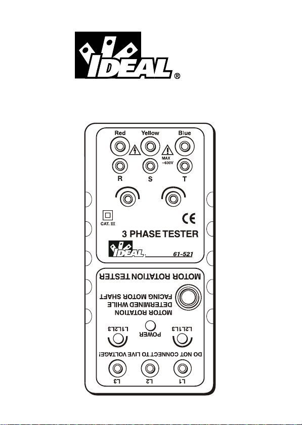
3 PHASE TESTER
&
MOTOR ROTATION TESTER
3
2
5
2
7
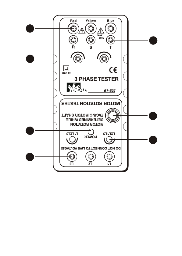
(1) PHASE ROTATION INPUT TERMINAL
(2) OPEN PHASE INDICATOR
(3) PHASE ROTATION INDICATOR
(4) MOTOR TESTER POWER SWITCH
(5) MOTOR TESTER POWER INDICATOR
(6) MOTOR ROTATION INDICATOR
(7) MOTOR ROTATION INPUT TERMINAL
2
2
2
4
26
Page 3
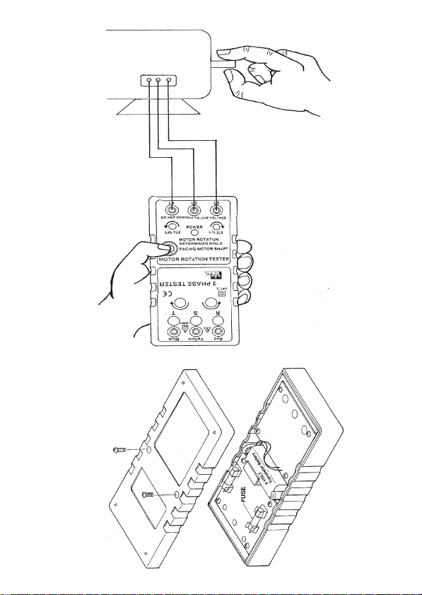
Fig.2
Fig.1
#6
1-
5
2
1
Page 4

1. Introduction
NOTE
This meter has been designed and tested
according to IEC Publication 348, Safety
Requirements for Electronic Measuring
Apparatus, IEC 1010 (En61010) and other
safety standards.
Follow all warnings to ensure safe operation.
CAUTION
READ "SAFETY NOTES" (NEXT PAGE)
BEFORE USING THE METER.
-1-
Page 5

2. Safety Notes
Read the following safety information carefully
before attempting to operate or service the
meter.
Use the meter only as specified in this manual;
otherwise the protection provided by the meter
may be impaired.
Rated environmental conditions :
(1) Indoor use.
(2) Installation Category lll.
(3) Pollution Degree 2.
(4) Altitude up to 2000 Meter.
(5) Relative Humidity 80% Max.
(6) Ambient Temperature 0~40 C.
Observe the International Electrical Symbols
Iisted below.
Meter is protected throughout by double
insulation or reinforced insulation.
o
2
Warning ! Risk of electric shock.
Caution ! Refer to this manual before using
the meter.
Alternating current.
~
-2-
Page 6

3. Features
Three functions in one unit, including open
phase, phase sequence and motor rotation
indication.
This model is ideal for installing conveyor lines,
pump systems and interconnected drivers.
Identifies 3-phase sequence and open phase
check.
Battery operated.
Meets IEC 1010(EN61010) safety requirements.
Complete with three large alligator clips.
-3-
Page 7

4. Measuring Methods
Operation of 3-Phase Rotation Tester :
(1) Connect the test lead to 3-phase input
terminals by R-S-T.
(2) Connect color alligator clips to the terminals
of a 3- phase power source. Connecting
order is optional.
(3) Make sure that all of the three lamps for open
phase check are on. If so, there is no open
phase. When any of the three lamps is not on,
there is open phase.
Open phase
check lamp
"R" is not on
Open phase
check lamp
"S" is not on
Open phase
check lamp
"T" is not on
(4) Check the rotating direction of the rotation
indicator.
Open phase on
terminal where
RED alligator clip
is connected
Open phase on
terminal where
YELLOW alligator
clip is connected
Open phase on
terminal where
BLUE alligator
clip is connected
-4-
Page 8

If the counter clockwise indicator is lit, alternate
the connection two of the three alligator clips.
When the clockwise indicator is lit and the
power source terminals are connected by the
RED, YELLOW and BLUE alligator clips, the
phase sequence indicators (R, S and T) shall
be lit respectively.
2
Operation of Motor Rotation Tester :
(1) Make sure there is no voltage present.
(2) Connect the test leads to motor input
terminals by L1-L2-L3, and press the power
button (Fig1). The power indicator green
lamp is lit. (If the clockwise or counter
clockwise red indicator is lit before rotating
the motor shaft, it means voltage is present.
Stop measuring. Take off the test leads and
turn off the external power). Rotate the
motor shaft clockwise. If the clockwise
indicator is lit, it means there is a 3-phase
motor connection to the power supply by L1L2-L3. The 3-phase motor should be rotated
clockwise.
(3) Connect the leads to 3-phase motor by
L1-L2-L3, and press the power button. The
power indicator green lamp is lit.
2
-5-
Page 9

Rotate the motor shaft counter clockwise.
If counter clockwise indicator is lit, it means
there is a 3-phase motor connection to the
power supply by L1-L2-L3. The 3-phase
motor should be rotated clockwise.
(4) If you require the motor to rotate counter
clockwise, you should change the
connection to L1-L2-L3. The motor should
be rotated counter clockwise.
2
-6-
-6-
Page 10

5. Specifications
Input Voltage : 100V AC up to 600V AC
max.
Frequency : 45 to 70 Hz.
Circuit Structure : All electronic (not
mechanical).
Power Requirement : 006P DC9V battery.
Power Consumption : Consumption current
approx. 14mA of motor
rotation field of tester.
AC power consumption
approx. 7mA per phase
rotation field of indicator.
Installation Category : IEC 1010 600V Cat. III.
Dimension : 153(L)
(6.02
Weight : Approx. 182g
Included battery.
Accessories : Test Leads(red, yellow &
blue), Soft Vinyl Case,
Instruction Manual, Battery.
x72(W)x35(D)mm.
x2.83x1.37 inch).
-7-
Page 11

6. Maintenance
Battery Replacement :
(1) It is necessary to replace battery, when green
lamp is dull lit.
(2) Use a screwdriver to unscrew the screw on
the back then open the case(Fig.2), remove
the battery and replace with new battery (type
006P, DC9V).
(3) Reinstall the case.
Fuse Replacement :
(1) It is necessary to replace fuse, when lamp
indicator R or T show no connection, and
change R-S-T is the same.
(2) Use a screwdriver to unscrew the screws on
the back then open the case(Fig.2), remove
the broken fuse and replace with new fuse
(200mA, 250V).
(3) Reinstall the case.
Cleaning and Storage :
WARNING
To avoid electrical shock or damage to the meter,
do not get water inside the case.
2
Periodically wipe the case with a damp cloth and
detergent. Do not use abrasives or solvents.
-8-
Page 12

If the meter is not in use for periods of longer than
60 days, remove the battery and store them
separately.
7. Warranty
This meter is warranted to the original purchaser
against defects in material or workmanship for one
year following the purchase of the tester. IDEAL
INDUSTRIES, INC. will, at its option, replace or
repair the defective unit, subject to verification of
the defect or malfunction.
Warranty limited solely to repair or replacement; no
warranty of merchantability, fitness for a particular
purpose or consequential damages.
IDEAL INDUSTRIES, INC.
Sycamore, IL 60178, U.S.A.
800-304-3578 Customer Assistance
www.testersandmeters.com
ND 2869-1
Made in Taiwan
 Loading...