

Page 1

IDEAL
SPRINT
RS 75
W all Mounted Balanced
Flue Combination Boiler
User’ s Instructions
CAUTION:
To avoid the possibility of injury during the use or cleaning
of this appliance care should be taken when handling the
edges of sheet steel components
July 1987
G.C. Appliance No.
Ideal SPRINT RS. 75 47 415 01
Page 2
Page 2
The Gas Safety Installation and Use Regulations: 1984
impose certain statutory obligations on gas users. Further
information may be obtained on application to the Gas Region.
It is the law that all gas appliances are installed by competent
persons, e.g. CORGI (identified by ) in accordance with the
above regulations.
Failure to install appliances correctly could lead to prosection.
It is in your own interest, and that of safety, to ensure that the
law is complied with.
ELECTRICAL SUPPL Y
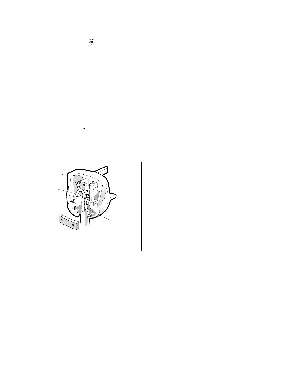
If a mains plug connection is used, it MUST be a 3-pin type,
wired as shown in Fig. 1, and fused at 3 amp.
The appliance MUST be efficiently earthed.
As the colour of the wires in the mains lead of this appliance
may not correspond with the coloured markings identifying the
terminals in your plug, proceed as follows:
The wire which is coloured GREEN AND YELLOW must be
connected to the terminal in the plug which is marked with the
letter E or by the earth symbol
or coloured GREEN or
GREEN AND YELLOW.
The wire which is coloured BLUE must be connected to the
terminal which is marked with the letter N or coloured BLACK.
The wire which is coloured BROWN must be connected to the
terminal which is marked with the letter L or coloured RED.
EARTH
(Green/yellow)
NEUTRAL
(Blue)
LIVE
(Brown)
Fig. 1
THREE-PIN PLUG
(T o BS.1363)
MINIMUM INSTALLATION AND SERVICING SIZES
Boiler size:
width 465mm (18 1/2in)
depth 300mm (12in)
height 900mm (36in)
The minimum clearances must be as follows:
Above the boiler 50mm (2in)
At each side of the boiler 10mm (1/2in)
Underneath the boiler 100mm (4in)
In front of the boiler 450mm (18in)
If the boiler is installed in a compartment it MUST NOT be used
for storage purposes.
The ventilation provided for the appliance during installation
MUST NOT be blocked and a check should be made
periodically that the ventilation areas are free from any
obstruction.
If it is known or suspected that a fault exists on the appliance it
MUST NOT be used until the fault has been corrected by a
competent person.
It is essential that the instructions in this booklet are strictly
followed for safe and economical operation of the boiler.
The IDEAL SPRINT RS.75 is a combination boiler providing
both central heating and instantaneous domestic hot water. The
two selector switches (G) and (J) permit the choice of hot water
only or central heating and hot water.
The dial on the control panel indicates the approximate system
temperature (upper scale) and the system pressure (lower
scale).
Note: If the normal COLD pressure of the system - indicated
by the red arrow on the dial - is seen to decrease over a
period of time then a water leak is indicated. In this
event your local Heating Installer should be consulted.
TO LIGHT THE BOILER
1. Check that the electricity supply to the boiler is OFF.
2. Lift off the controls compartment front cover.
3. Ensure the boiler HEATING switch (G) and WATER switch
(J) are in the OFF position.
4. Turn the gas control knob (F) CLOCKWISE until resistance
is felt and then release it.
WAIT for three minutes.
5. Push in the gas control knob (F) and hold it depressed. Push
in and release the ignition button (D) repeatedly until the
pilot flame can be seen through the sight glass (A).
When the pilot has lit, continue to press in the gas control
knob for a further fifteen seconds.
6. Should the pilot go out at this, or any other stage, turn the
gas control knob (F) CLOCKWISE and release it.
WAIT for three minutes and then repeat ‘5’ but WAIT FOR
LONGER THAN FIFTEEN SECONDS before releasing the
gas control knob.
7. Switch ON the electricity supply to the boiler and check all
external controls, e.g. room thermostat, etc., are ON. The
Mains On neon will glow.
8. Set the HEATING and WATER switches to the desired
positions:
(a) HEATING and HOT WATER MODE
When central heating and domestic hot water are required,
both switches should be set to ON.
The HEATING and WATER indicator neons (H) and (I)
respectively, will both glow.
The boiler will supply the central heating but will give priority
to the domestic hot water when required.
or (b) HOT WATER MODE.
When domestic hot water only is required the WATER switch
should be set to ON and the HEATING switch set to OFF.
The WATER indicator neon (I) will glow and the boiler will
only fire when domestic hot water is drawn off.
9. Replace the controls compartment front cover.
TO SHUT DOWN THE BOILER
1. For short periods:
Set the boiler HEATING switch (G) and WATER switch (J) to
OFF.
When heating is again required - restore the switches to
their original settings.
Page 3

Page 3
Fig. 2
BOILER CONTROLS
LEGEND
A. Sight glass
B. MAINS ON indicator neon
C. Pressure/temperature gauge
D. Piezo unit ignition button
E. Gas service cock
F. Gas valve control knob
G. HEATING switch
H. HEATING indicator neon
I. WATER indicator neon
J. WATER switch
2. For longer periods:
Set the boiler HEATING switch (G) and WATER switch (J)
to OFF.
Turn the gas control knob (F) CLOCKWISE until
resistance is felt, and then release it in order to extinguish
the pilot burner.
Switch the electricity supply to OFF.
WARNING.
If no frost protection is provided and frost is likely during a
short absence from home, leave the heating controls (if fitted) at
a reduced temperature setting.
For longer periods the entire system should be drained,
including the domestic water supply.
If the system includes a frost thermostat then, during cold
weather, the boiler should be turned OFF at the time switch (if
fitted) only.
The mains supply should be left switched ON with the boiler
HEATING and WATER switches remaining in the OFF positions.
Page 4

BOILER OVERHEA T THERMOSTA TS
The boiler is fitted with two safety “cutout” thermostats which
may shut the boiler down in the event of overheating.
If thermostat No. 1 operates, the pilot will be extinguished.
If thermostat No. 2 operates, the main burner will not fire but the
pilot will remain alight.
Should this occur then turn off the boiler and consult your local
Heating Installer.
CONTROL OF WATER TEMPERATURE
1. Central Heating
The boiler control thermostat automatically switches the
main burner OFF and ON to maintain the pre-set
temperature, and no adjustment is necessary.
2. Domestic Hot Water
The domestic hot water draw-off temperature can be
controlled by adjusting the flow rate at the tap - the lower the
draw-off rate, the higher the temperature and vice-versa.
The maximum draw-off temperature is limited by the
modulating gas control which reduces the main burner flame
at low draw-off rates.
3. The pilot burner remains alight continuously to give reignition of the main burner.
TO RELIGHT THE BOILER
Repeat the procedure 1-9 detailed in “to Light the Boiler”.
ESCAPE OF GAS
Should a gas leak be suspected, contact your Local Gas Region
without delay.
Do NOT search for gas leaks with a naked flame.
CLEANING
For normal cleaning simply dust with a dry cloth. To remove
stubborn marks and stains, wipe with a damp cloth and finish off
with a dry cloth.
Do NOT use abrasive cleaning materials.
MAINTENANCE
The appliance should be SERVICED AT LEAST ONCE A YEAR
by a qualified Heating Engineer or your local Gas Region.
Ideal Boilers, P .O. Box 103, National A ve, Kingston upon Hull,
HU5 4JN. Telephone: 01482 492 251 Fax: 01482 448 858.
Registration No. London 322 137.
November 2002 UIN 116 011
Caradon Ideal Limited pursues a policy of continuing improvement
in the design and performance of its products. The right is therefore
reserved to vary specification without notice.
I
deal Installer/Technical Helpline: 01482 498663
www.idealboilers.com
 Loading...