

Page 1

TM
SIGNALTEK
Cable Performance Tester
Operation Manual
Rev B. JAN 07
IDEAL INDUSTRIES Inc. 1-1
Page 2

Page 3

This document conta ins inf ormati on propr iet ary to IDEAL
INDUSTRIES, Inc. The information in this document is not to be
used or duplicated in any manner without prior written approval
from IDEAL INDUSTRIES.
IDEAL INDUSTRIES and the ID EAL INDU STR IES logo ar e
registered tr adem arks of IDE AL INDU STRIES.
All other produc t names menti oned i n this book ar e tradem arke d or
copyrighted by their res pective manufactur ers.
IDEAL INDUSTRIES, Inc.
Becker Place
Sycamore, IL 60178 USA
Phone: (800) 435-0705
Fax: (800) 533- 4483
Manual Part No. 6510-91-0003 Rev. B
© 2006, IDEAL INDUSTRIES, Inc.
IDEAL INDUSTRIES Inc. i
Page 4

IDEAL INDUSTRIES STANDARD WARRANTY POLICY
IDEAL INDUSTRIES w arr ants tha t all SI GNAL TEK Pro ducts
manufacture d or proc ured by IDEA L INDU STRIES co nfor m to
IDEAL INDUSTRIES’ publishe d s pecific ations and ar e free fr om
defects in materials and workmanship for a period of two (2) years
from the date of d elivery to the ori ginal Buyer, w hen us ed und er
normal oper ating c on diti ons an d with in t he ser vic e c ondit ions f or
which they are designed. This warranty is not transferable and
does not apply to used or demonstr atio n products.
The obligation of IDEAL INDUS TRIES arisi ng from a Warranty
claim shall be l imite d to r epairi ng, or at its op tion, r epl acing without
charge, any assem bly or compon ent (except b atteries an d cabl e
adapters), which in IDEAL INDUSTRIES’ sole opinion proves to b e
defective within th e scop e of t he W arr anty. In the event IDE AL
INDUSTRIES is not able to modify, repair o r repl ace
nonconforming defective parts or components to a condition as
warranted within a reasonable time after receipt thereof, Buyers
shall receive cr edit i n the amou nt of the or igin al inv oiced pr ice of
the product.
IDEAL INDUSTRIES must be notif ied i n writi ng of th e defect or
nonconformity within the Warranty period and the affected Product
returned to IDEAL INDUSTRIES’ factory, designat ed Service
Provider, or Aut horiz ed Serv ice C ent er withi n thirty (3 0) days after
discovery of such defect or nonconformity. Buyer shall prepay
shipping charges and insurance for Products returned to IDEAL
INDUSTRIES or its designat ed Ser vice Pro vid er for war ranty
service. IDEAL IND USTR IES or its des ignat ed Serv ice Pr ovi der
shall pay costs for return of Products to Buyer.
IDEAL INDUSTRIES s hall have n o responsi bility f or any def ect or
damage caused by im proper stor age, impr oper inst allatio n,
unauthorized modification, misuse, neglect, inadequate
maintenance, a ccide nt or for a ny Product whic h has bee n repa ired
or altered by anyone ot her tha n IDEA L INDU STRIES or its
IDEAL INDUSTRIES, Inc. ii
Page 5

authorized repr esenta tive or n ot in accordan ce with i nstructions
furnished by IDEAL IN DUST RIES.
The Warranty describ ed above is Buy er’s s ole and exc lusiv e
remedy and no other w arranty, whether wr itte n or oral, ex press ed
or implied by statute or cour se of deali ng shall a pply. IDEAL
INDUSTRIES specific ally d isclai ms the impli ed warrantie s of
merchantability and fitness for a particular purpose. No statement,
representati on, agreem ent, or underst anding, or al or wri tten, made
by an agent, distribut or, or employe e of IDEAL INDU STRIES,
which is not cont ain ed i n the f ore going W arr anty w ill be bi ndin g
upon IDEAL INDUSTRIES, unless made in writing and executed
by an authorized representative of IDEAL INDUSTRIES. Under no
circumstances shall I DEA L INDU STRI ES be l iabl e for any dir ect,
indirect, specia l, inc idental , or consequential damages, expenses,
or losses, including l oss of pr ofits, b ased on c ontract, tort, or any
other legal theory.
SIGNALTEK Operatio n Manual iii
Page 6

Table of Contents
Table of Contents .........................................................................iv
Table of Figures............................................................................vi
1 Introduction.................................................................................1-1
Cable Qualificati on Testin g........... ... ... .......................................1-1
SIGNALTEK Test Functions......................................................1-3
Cable Types................................................................................1-4
Cable types that c an be t ested with SIGNA LTEK:...................1-6
Test Port and C able Ada pters......... . .. .......................................1-6
Standard Accessories ................................................................1-6
Optional Accessories..................................................................1-7
Memory .......................................................................................1-7
Tests:...........................................................................................1-7
Batteries & Power.................................................................... 1-12
Battery Charging Warnings.....................................................1-14
Graphical User I nterfac e Nav igatio n.......................................1-15
User Interface Navigation........................................................ 1-16
2 Setup and Configuration...........................................................2-1
Wire map Display Color Code ...................................................2-1
Autotest Preferences..................................................................2-2
Autotest Modes...........................................................................2-3
Cable Perform ance S etup.... ... .. .. .. .. .. .. .......................................2-4
IP Address Setup........................................................................2-6
Ping Setup...................................................................................2-7
Device Defaults...........................................................................2-8
Owner Information......................................................................2-9
Display Preferences ...................................................................2-9
Timeout Options ......................................................................2-10
Measurement Units ................................................................. 2-11
Date and Time......................................................................... 2-11
Cable ID Prefix......................................................................... 2-12
Language................................................................................. 2-13
Restore Factory Defaults ........................................................ 2-13
Updating Firmware.................................................................. 2-14
IDEAL INDUSTRIES, Inc. iv
Page 7

3 Test Storage and Management................................................3-1
Using the Job Ta b Fu ncti ons........ . .. .. . .......................................3-1
Printing and Copying to USB Drives .........................................3-2
Direct PC Connection (Windows XP™ only) ............................3-3
Copy to External USB Drive.......................................................3-3
Printing Directly to a USB Printer...............................................3-4
4 Running Autotests.....................................................................4-1
Beginning an Autotest................................................................4-2
Stopping an Autotest..................................................................4-3
Active Link Testing .....................................................................4-3
No-Link Testing...........................................................................4-4
Manual Tests ..............................................................................4-4
5 Test Results................................................................................5-1
Wire map Results.......................................................................5-1
Wire map Testing Activ e LAN Lin ks..........................................5-2
Link Establishment .....................................................................5-2
Bit Error Rate Tests....................................................................5-3
Performance Test Failures.........................................................5-5
6 Fiber Optic Testing ....................................................................6-1
Overview .....................................................................................6-1
Fiber Qualification Abilities......... ... ... ..........................................6-2
Setup and Calibration.................................................................6-4
7 Troubleshooting & Frequently Asked Questions.................7-1
8 Care and Calibration..................................................................8-1
9 Specifications.............................................................................9-1
10 Customer Service ................................................................. 10-1
IDEAL INDUSTRIES World W ide Contac t Inf ormati on.........10-2
SIGNALTEK Operatio n Manual v
Page 8

Table of Figures
Figure 1-1 T-568 A/B Color Code ..................................................1-5
Figure 1-2 SIGNALTEK Handsets .................................................1-9
Figure 1-3 Battery Disc harge C haract eristics.............................1-13
Figure 1-4 AutoTest Tab - Active ................................................ 1-16
Figure 1-5 AutoTest Tab - Inactive..............................................1-17
Figure 2-1 Setup Tab......................................................................2-1
Figure 2-2 Wire map Dis play Pre ferenc es.....................................2-2
Figure 2-3 Autotest Pref erences........ ... .........................................2-2
Figure 2-4 Remote Detected..........................................................2-3
Figure 2-5 Active LAN (Link) Detected ..........................................2-3
Figure 2-6 No Link Detected...........................................................2-3
Figure 2-7 Cabl e Perfor manc e Setup............................................2-5
Figure 2-8 VoIP Setup ....................................................................2-6
Figure 2-9 IP Address Se tup.. .. ... .. ... ... ...........................................2-7
Figure 2-10 Ping Setup...................................................................2-8
Figure 2-11 Owner Information ......................................................2-9
Figure 2-12 Display Contrast....................................................... 2-10
Figure 2-13 Timeout Options....................................................... 2-10
Figure 2-14 Measurement Units..................................................2-11
Figure 2-15 Date and Time.......................................................... 2-11
Figure 2-16 Cable ID Prefi x Setup..............................................2-12
Figure 2-17 Language Setup....................................................... 2-13
Figure 2-18 Factory Defaults...................................... .................2-13
Figure 2-19 Firmware Version..................................................... 2-14
Figure 3-1 Job Tab..........................................................................3-1
Figure 3-2 USB Printer Cable.........................................................3-4
Figure 4-1 Autotest Tab ..................................................................4-1
Figure 5-1 Wire map Results..........................................................5-1
Figure 5-2 Link Esta blishm ent Resu lts..........................................5-3
Figure 5-3 Cab le Per for manc e Res ults. .. .......................................5-4
Figure 6-1 SIGNALTEK-FO Top Connectors................................6-2
Figure 6-2 LC-to-SC cable..............................................................6-3
Figure 6-3 SC Coupler......................................... ...........................6-3
IDEAL INDUSTRIES, Inc. vi
Page 9

Figure 6-4 Calibration Setup...........................................................6-4
Figure 6-5 Calibr ati on Compl ete Scre en .......................................6-5
Figure 6-6 Fiber Li nk Establis hment............................................. 6-5
SIGNALTEK Operatio n Manual vii
Page 10

Page 11

Introduction
1
SIGNALTEK is a unique cabling tester that offers the user the
ability to test the perfor manc e of a wi de rang e of i nsta lled cabl e
system characteristics. With S IGNA LTEK, the us er c an v erify
network perfor mance, troubles hoot conn ectivity pr oblem s, and
view network s peeds t o determ in e if t he instal led c abl e pr ovides
the necessary per form ance t o sup port d esired applic ations.
• SIGNALTEK is easy to use. It offers any installer th e ability t o
perform cable perf ormanc e tests an d rapidly locat e
connectivity issues.
• SIGNALTEK will generate performance repor ts th at can b e
viewed and print ed wit h any w eb br owser. N o spec ial soft ware
is necessary makin g it easy to view, pr int, an d sh are test data.
• SIGNALTEK can test c able links in one of thr ee c ondit ions:
Terminated with the SIGNALTEK remote device; Active LAN
Links that term in ate t o a hub, s witc h, or PC; or to a sin gleended link that is not terminated to a device at the opposite
end.
• SIGNALTEK uses two test handsets that allow full-duplex
performance test ing of cables at Ethern et sp eeds of up t o 1
Gigabit per second (1Gbps).
Cable Qualification Testing
Most cable i nstall ers are f ami liar w ith TIA-568 or IS O- 11801
cabling standards. All c able cer tif icatio n instrum ents such as
IDEAL LANTEK Certif iers perf orm m easurem ents to thes e
standards at frequency r anges sp ecifie d by thes e sta ndards. The
concept behind cert ificat ion t esti ng is that t he ca ble is bei ng test ed
to provide supp ort for any com munic ati ons pr otoc ol t hat op erates
in a given frequ enc y ra nge. Fo r som e install ations this le vel of
IDEAL INDUSTRIES Inc. 1-1
Page 12

testing is critical beca use t he ca bling instal ler do es n ot nec essarily
know what type s of devi ces ar e goin g to us ed on t he network.
For example, a netw ork that h as been c ertifie d to meet the
requirements f or Cat eg ory 5e perf orma nce c an s up port v ario us
applications such as 10/100/1000 Mbps Ethernet, 155Mbps ATM,
RS-488, RS-232, and many more. However, it is often the case
that in any reside ntial or c ommerc ial n etwork, Ether net devic es wil l
be the only typ e us ed.
SIGNALTEK uses the IEEE 802.3 ab (Gigabit Ethernet) standar d
as a refere nce for c abl e perf or manc e test ing. Rat her t han a
traditional certi ficat ion t est where frequ ency-b ased par ame ters
such as Near E nd Cr osstalk ( NEX T) and re turn l oss ar e me asur ed,
performance or q ualificat ion t esting , as it is s ometim es calle d, is a
Bit Error Rate Test (B ERT). D ata p ackets a re se nt dow n th e cabl e
to the remote handset then re-transmitted back to the display
handset where t he numb er of lost or err ored pa ckets is co unted.
The results are dis pl ayed f or t he us er t o get a n insta nt view of t he
cable’s perform ance. A ca ble perf orm ance t est is marked as a
“pass” or “fail” based on the I EEE 80 2.3ab param eters wh ich
specify the num ber of error pa ckets allowe d in a giv en test tim e.
The IEEE (Institut e of Electr ical and Electr onic Eng ineers) has
created a set of standards that allows hardwar e and softwar e to
perform over a vari ety of medi a. U nlike the EIA/TIA wh ich s pecifi es
cabling limits to s uppor t variou s comm unic atio ns pr otoco ls, t he
IEEE creates the actual pr otocols . The 802 struc ture addr esses th e
following tra nsmissi on proto cols :
• 802.3 Ethernet over a phys ical medium (tw isted pair )
• 802.4 Token passing over a Bus topology
• 802.5 Token passing over a Ring topology
• 802.11 A family of wireless signaling standards (Wi-Fi)
• 802.12 Shared medi a stan dard t hat w ill supp ort Et her net an d
Token Ring on the s ame phys ical n etwork
IDEAL INDUSTRIES, Inc. 1-2
Page 13

SIGNALTEK Test Functions
SIGNALTEK can perform a var iety of both passive and act ive test s
on communications cabl e. The pass iv e tests are th ose w her e
SIGNALTEK is co nnecte d to bot h ends of t he c abl ing l ink. Activ e
tests are those in which one end of the link is connected to an
active network devic e such as a PC, switch, router or othe r device
and the opposit e end of the link is co nnect ed t o the SI GNALTE K
handset.
• Wire map – D ispl ays t he phys ical p arin g of t he c abl e. A ls o
displays the length of e ach pair, t he cond ition of the
termination (te rmin ated, ope n, sh orted) and t he del ay skew
when a Gigabi t link is establi shed.
• Link Establishm ent – D ispl ays the f astest Ether net s peed t hat
SIGNALTEK was able to esta blis h on the li nk. When the li nk is
terminated with a SIGNA LTEK remote hands et, Link
Establishment will dis play 10, 10 0 or 1000 Mbps dependin g on
the quality of the ca bling. When connected to an active LAN
link, Link Establishm ent will dis play th e fastes t speed that was
negotiated with the remote switch/ hub/NIC.
• Cable Performanc e – Disp lays the BERT dat a results for l inks
tested between the SIGNALTEK display and remote handsets.
Information dis playe d include s: packet size, t otal nu mber of
packets transmitted, number of packets received, number of
packets with errors, a nd a percent age bar gr aph of each.
Note: The setup options allow the Cable
Performance test to be run with default IEEE
802.3 parameters or customized with a user
defined test time a nd f ailur e thr es hold.
• VoIP (Voice over IP) P erf ormanc e – Simila r to t he C able
Performance test ex cept t hat the pack ets ar e smaller to
accurately simulate VoIP transmissions.
SIGNALTEK Operatio n Manual 1-3
Page 14

• Web Performanc e – Per forma nce te st that s imulat es the size
and payload of typical internet packets.
• IP Video Performanc e – Perfor mance test th at simulat es the
size and payload of typica l IP vi deo applic atio ns.
Note: IP Video is not the same as CATV
broadband video. This test is useful to test twi sted
pair links that will be used to suppo rt IP cameras
for security applications.
• DHCP – When connected to active Ethernet networks the
display handset will locate a DHCP (Dynamic Host
Configuration Pr otoc ol) ser ver a nd request a n IP addr ess fro m
the server. The dat a displaye d is: SIGN ALTEK ’s IP address, IP
address of the DH CP s erv er, th e IP address of the ne twork
router, IP su bnet, and t he nam e of t he inter net servic e provi der
(ISP).
• Ping – Displays the results of the ping test when S IGNA LTE K
is connected to an acti ve Ethe rnet n etwor k. T he us er can
choose the targe t IP ad dress to ping, t he p acket s ize, the
number of packets to send, the delay between packets, and
the failur e thr esh old.
Cable Types
SIGNALTEK is comp atib le with a vari ety of cabl e type s an d
configuratio ns. Cable Perf orma nce tests can be run on any type of
twisted pair cable that s uppo rts Ethernet . S ince 10/100 E thern et
requires a minim um of two pairs to operate, ca bles w ith only o ne
pair cannot be tested for Ethernet performance, this inc ludes c oax
cable types .
When performi ng a Ca ble Per form ance test it is imp ortant t o
consider the ph ysic al wiri ng re quirem ents o f Ether net. If the c abl e
is not wired in a co mpati ble ma nner, t he C abl e Perfor manc e test
will be unabl e to r un s ince an Ether net link can not be establ ished.
IDEAL INDUSTRIES, Inc. 1-4
Page 15
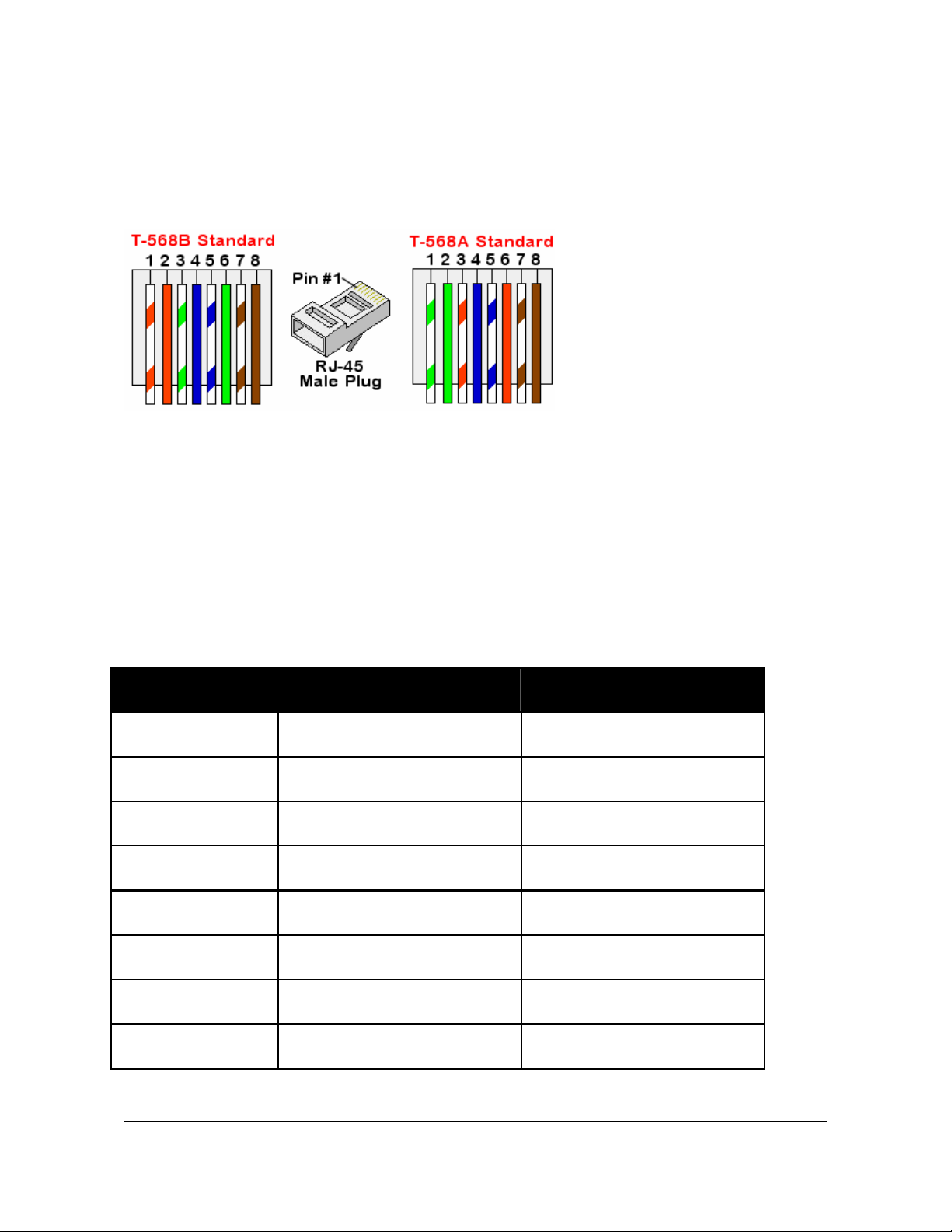
10/100 Ethernet requires two twisted pairs to be terminated to the
RJ-45 connector. Each transceiver will transmit on pins 1/2 and
receive on pi ns 3/6.
Figure 1-1 T-568 A /B Col or C ode
There is no performanc e differ ence between T5 68-A and T568-B
wiring config urati ons. How ever m ost standa rds r ecomm end t he
use of the T568-A c onfig urati on si nce it provi des bett er
compatibility with telephone wiring used in residential applications.
Gigabit Ethernet (100 0Base- T) oper at es over C ateg ory 5 or bett er
cable and utilizes a ll four p airs of th e cable.
Table 1-1 Ether net Sign aling
RJ-45 Pin # 10/100 Mbps 1000Mbps
1 Tx + Bi-Dir A +
2 Tx - Bi-Dir A 3 Rx + Bi-Dir B +
4 Unused Bi-Dir C +
5 Unused Bi-Dir C 6 Rx - Bi-Dir B 7 Unused Bi-Dir D +
8 Unused Bi-Dir D -
SIGNALTEK Operatio n Manual 1-5
Page 16

Cable types th at ca n be t ested with SIGNA LTEK:
• CAT 3 UTP
• CAT 3 STP
• CAT 5e UTP
• CAT 5e STP
• CAT 6 UTP
• CAT 6 STP
• CAT 6a UTP
Test Port and Cable Adapters
SIGNALTEK is configur ed to allow testing of th e follow ing
interfaces :
• RJ45, 4 pair UTP/STP
• RJ12, 3 pair UTP Telephone wire
• CAT 6a STP
• CAT 7 STP
• USOC (3 pair)
• Single Pair
• RG6
• RG59
• Coaxial Connector Type “ F”
Standard Accessories
• 2 x RJ45 STP Cat 5e patch cord
• 2 x RJ45 to RJ12 silver satin telephone patch cord
• 2 x RJ45 to coaxial “F” adapter cord
• 2 x RJ12 to alligator clip cable
• 2 x RJ45 to RJ12 adapter
• USB “A” to mini “B” cable
• 8 x AA alkaline batteries
• Soft-sided carrying case
IDEAL INDUSTRIES, Inc. 1-6
Page 17

Optional Accesso ries
• 120-240 volt AC power adapter with multi nati onal plugs ( Part
Number 4010-00-0136)
Memory
SIGNALTEK test records are stored internally in the display unit
and can be copied t o a USB memory driv e. Inter nal m emory
capacity is approxi mately 20, 000 re cords. Exter nal mem ory
capacity is limited only by the s ize of th e USB me mory driv e.
Stored record fil es can b e copied t o a PC u sing a c ommon USB
memory drive device or be transferr ed to the PC from the
SIGNALTEK with the provided USB cable.
Tests:
The following t able i ndicat es which t ests c an be r un on a v ariety of
cable types .
Note: All cable performance measurements
require the presence of at least two pairs of wires
terminated in accordance with the TIA-568 A/B
wiring configuration. Cable performance tests
cannot be run on cables terminated with the
USOC wiring c o nfi g uration or on cables with few er
than 2 pairs of conductors (i.e. coax, alarm,
speaker wire).
SIGNALTEK Operatio n Manual 1-7
Page 18

Table 1-2 Cab le Test Abilit y Ch art
Cable Typ es
Data
CAT 5 UTP X X X X X X X X
CAT 5e UTP X X X X X X X X
CAT 6 UTP X X X X X X X X
CAT6a UTP X X X X X X X X
CAT 5 STP X X X X X X X X
CAT 5e STP X X X X X X X X
CAT 6 STP X X X X X X X X
CAT 6a STP X X X X X X X X
CAT 7 STP X X X X X X X X
Phone
CAT 3 - 3 pair X X X X X X X 10/100
Mapping
Shorted Pairs
Opens
Reversed Pairs
Length
Distance to Open
Distance to Short
Cable Performance
(10/100/1 00 0Mb p s)
CAT 3 - 4 pair X X X X X X X X
Coax
RG 59/6 X X X X X X
Misc.
2-Wire X X X X X X
IDEAL INDUSTRIES, Inc. 1-8
Page 19
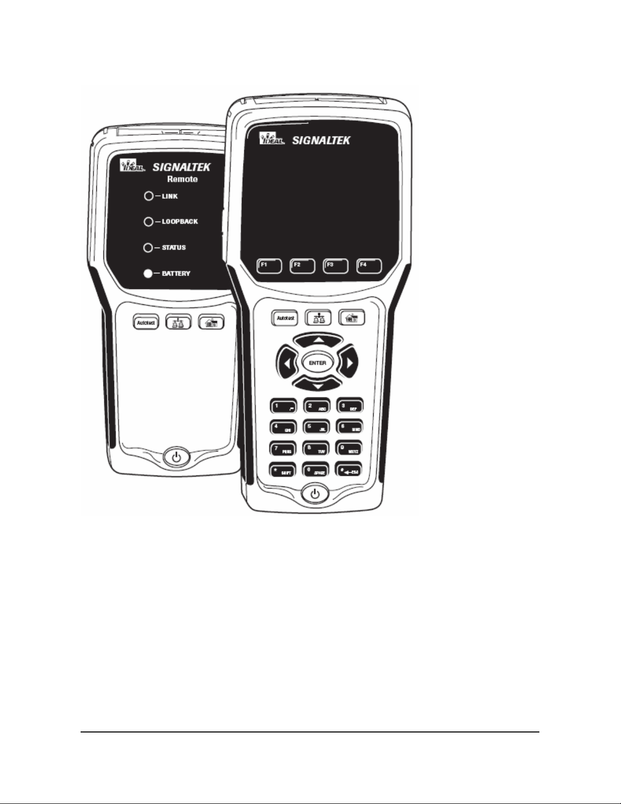
Figure 1-2 SIGNALTEK H andset s
The following t abl e descri bes the function of each button and LED
on the SIGNALTEK handsets.
SIGNALTEK Operatio n Manual 1-9
Page 20

Table 1-3 Key and LED Functions
Button Function
F1-F4 keys are used t o p erform different functi ons depending
on the current scre en. Options f or these ke ys are displ ayed
on the LCD above ea ch key.
When pressed, the SIGNALT EK display will automatical ly
change to the Autotest tab and begin running an Autotest.
Pressing the Aut otest button o n the r emote handse ts will also
initiate an Autotest.
Brings up the Manual tab. Individual tests can be selected
and run for diagnostics or troubleshooting. Manual tests
cannot be stored to memory.
Pressing this button on the remote handset while connected
to an active LAN port w ill dis play t he spee d of t he devic e (PC
or switch) at the other end of t he link.
Brings up the J ob t ab wh ere t he nam e of eac h job f older and
the number of stor ed t ests ar e displ ayed.
The directional keypad and Enter keys are used to navigate
around the SIGN ALTE K user int erfac e. W hen t he t ab col or is
yellow, the left and ri ght arrow key s are use d to move
between the tabs. Pressing up or down scrolls through the
options within each tab. To change tabs, make sure to press
up or down until the t ab c olor c hanges back to y ellow.
The alpha-num eric k eys ar e us ed to e nter t ext an d numb ers
into various f ields i n the SIGN ALTE K user int erf ace. Press ing
a key multiple ti mes will cycle thro ugh the let ters an d number
on that key. Us e th e left arrow on t he dir ecti onal k ey pad t o
backspace and er ase t he cha racter to th e left of t he c ursor.
IDEAL INDUSTRIES, Inc. 1-10
Page 21
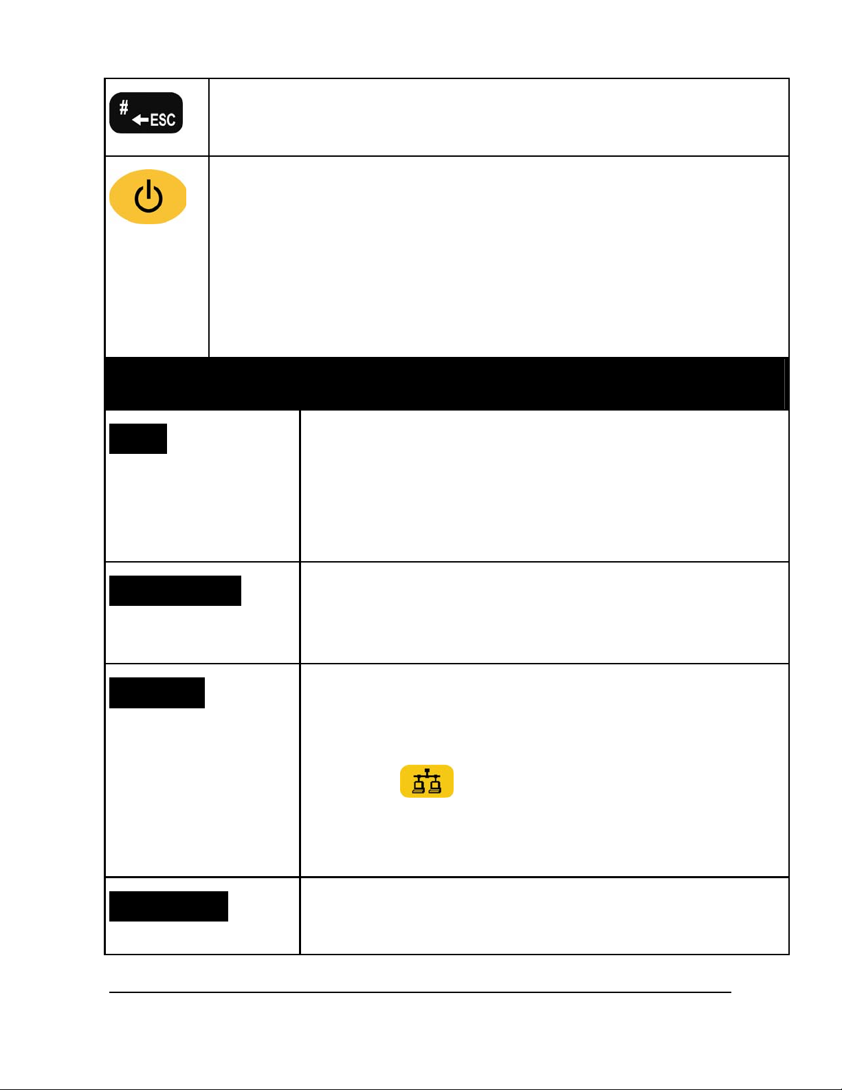
The # key also funct ions a s Escape to r eturn to t he pr evious
screen.
The power button turns SI GNAL TEK on and off an d also
controls the back lig ht brightne ss. To tur n on, pr ess an d
release the b utton. To tur n the pow er off, p ress and H OLD
the button until the scr een tur ns off, t hen rele ase. Tap t he
button to cycle b etween the thre e backl ight bri ghtn ess levels ;
High, Low, and Off.
Press and hold for 5 s econ ds to turn off the remote handset.
Remote Handset Functions
LINK LED
LOOPBACK LED
STATUS LED
Indicates the det ection of the S IGNA LTEK dis play
or an active LAN device. Lights green when the
remote detects that it is connected to the display
handset. Lights red when the r emote detects
another active LAN devic e such as a switch .
Lights green whe n a cabl e perf orma nce test is
running. Indicat es that a li nk is establ ished and the
handsets are transmitting data to e ach ot her.
During a test, flashes green to indicate a test is in
progress. After a test, l ights g reen to i ndicat e a
pass or red to indicate a fail.
When the
to an active LAN, the S TATUS LED lig hts red t o
button is pressed whil e conn ected
indicate 10Mbps, flas hes green to indicate 100Mbs,
or lights steady green to indicate 1000Mbps.
BATTERY LED
SIGNALTEK Operatio n Manu al 1-11
Lights green, oran ge, or re d to indic ate batt ery
charge status.
Page 22

Batteries & Power
Each SIGNALTEK hands et is power ed by four AA batteri es.
Alkaline batteries are included . User s uppli ed NiMH or NiC d
rechargeable batter ies may be used i n either handset.
The optional AC-DC power supply may be used to powe r the
handsets for extended periods of time.
If using recharge abl e batter ies, th ey m ust be c harge d in an
external char ger. Th e Gigabit tra nsceiv er in th e handsets dr aws a
considerable am ount of pow er wh en perf ormi ng c abl e tests,
therefore high- capacit y NiMH batter ies are r ecomm ended . Bat tery
capacities of 2300-25 00mAh will provi de the be st runtime between
charges.
Note: The power inpu t por t is only u sed t o provide
power to the handsets. It will not charge batteries
that are installed in the handsets. This is a safety
feature as accidental charging of alkaline batteries
can cause the batteries to rupture, possibly
damaging th e instr ument or c aus ing bo dily har m.
SIGNALTEK consum es pow er eve n when turn ed off. W hen not
used for several days it is recommended that the batteries be
removed from the handset to prev ent accidental dr ain. A s an
alternative, a sm all piec e of paper or plastic c an be insert ed
between one of the b atteri es and a n electri cal c ont act to br eak th e
electrical circ uit.
Alkaline batteries can leak when left in an
electrical device for an extended period of time.
This can cause damage to the electrical circuits in
SIGNALTEK. Please take the actions above to
prevent dam age to y our t ester.
SIGNALTEK’s battery li fe indicat or is calibr ated for stand ard
alkaline (1.5 volt) cel ls. Usi ng rec harge able batt eries will c aus e the
IDEAL INDUSTRIES, Inc. 1-12
Page 23
battery indicator t o behave dif fere ntly t han it does wit h alkali ne
batteries becaus e of t he differ ent cel l volta ge and d ischar ge
characteristics.
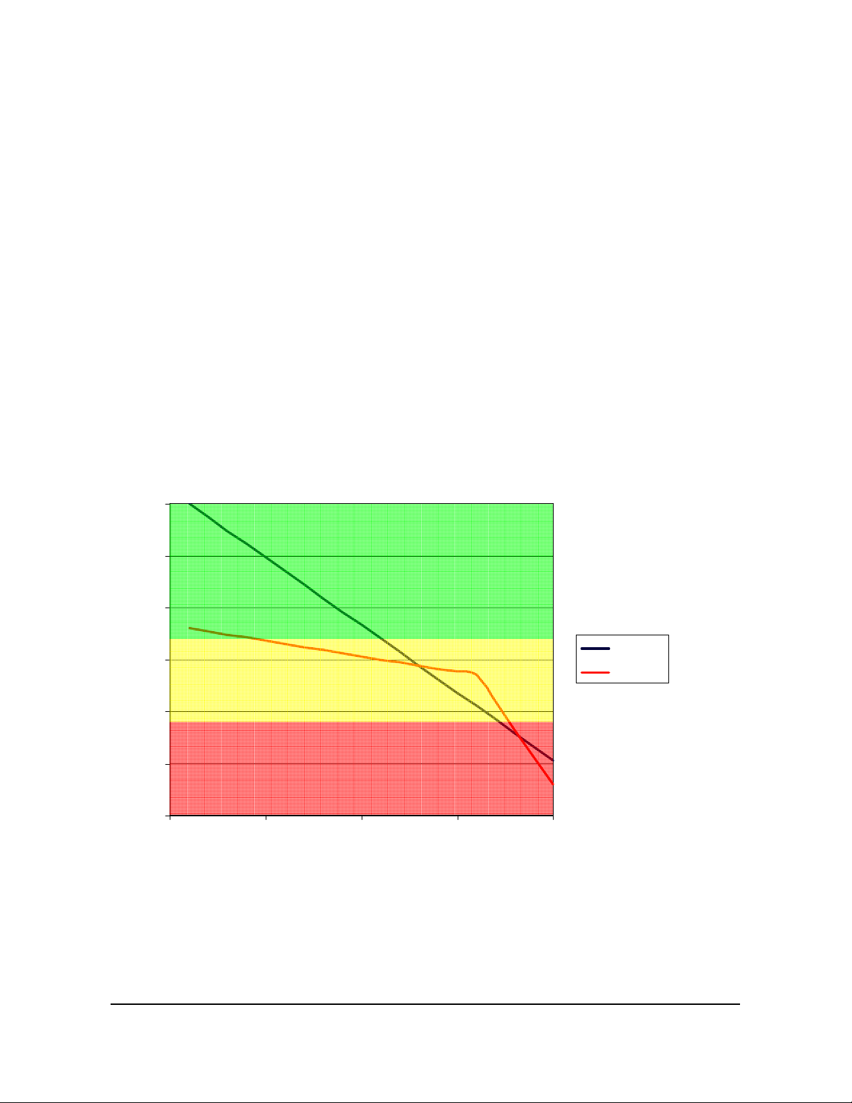
Alkaline batteri es disc har ge in a linear f ashi on an d the battery
indicator will gradua lly c hange from gr een t o yellow to re d.
Rechargeabl e batteri es s uch as NiM H have a lo wer star ting
voltage (1.2 volts per cel l) and will h old a c onsta nt volt age for most
of their life then su ddenly disc harge v ery rapi dly.
When using NiMH batt eri es the i ndic ator w ill rem ain gr een for a
short time, and th en tur n yellow for mos t of th e life o f the batt eries.
Once the indicat or tur ns red th e pack is n early c om pletely
discharged and the test er will turn off very shortl y becaus e of the
discharged battery pack.
Figure 1-3 B att ery Di scha rge C har acte risti cs
6
5.5
5
4.5
Volts
4
3.5
3
0 5 10 15 20
Time
Alkaline
NiMH
SIGNALTEK Operatio n Manu al 1-13
Page 24

Battery Charging Warnings
The DC power input port is not designed to charge batteries that
are installed in SIGNALTEK. However, it is possible that a
component f ailur e may c ause t he unit to charg e batt eries caus ing
the batteries to ru pture, dam aging t he SIGNALTE K or causi ng
personal injury.
To prevent accident al ch arging, IDEAL rec ommen ds that t he
external power adapter s only b e used w hen batter ies are n ot
installed in the tester.
IDEAL INDUSTRIES, Inc. 1-14
Page 25

Graphical User Interface Navigation
When turned on, SIGNALTEK will display the firmware version
number then boot up to t he AutoT est tab. T his s ection o f the
manual will describe the various screens and the i nformati on
displayed in each screen.
There are fo ur prim ary dis play scr eens i n the S IGNALTE K
graphical user interface.
• AutoTest – Displays the t ests t hat will be run w hen t he A utotes t
button is pr essed. Als o lets t he us er ch oose t he ca ble ID that
will be used for the next test. Each time an Autotest is run the
results are automatic ally s tored t o t he inter nal m emory in t he
active job file.
• Manual – Displays a listin g of tes ts that can be run indiv idually.
Selecting a test w ith the u p/down ar rows then pres sing F1 will
run a test. Test s run from the Ma nual tab ca nnot be sav ed.
• Job – Displays a listi ng of curr ent job f iles. Jobs can b e added,
edited, or delete d. Selectin g a job and pr essing Ent er will
display a list of tests stored in that job. Pressi ng Ent er agai n
will display the results of individual tests.
• Setup – Displays a listi ng of options for the oper ati on of
SIGNALTEK.
SIGNALTEK Operatio n Manu al 1-15
Page 26

User Interface Navigation
Figure 1-4 A uto Test Tab - A cti ve
Active Job (1)
Function Tabs (2)
Link Status (3)
Date/Time (4)
Battery Status ( 5)
IDEAL INDUSTRIES, Inc. 1-16
Page 27

Figure 1-5 A utoT est Tab - I nact ive
The
user interfac e. I n Figur e 1-4, n otice the color of the f unctio n t abs.
The selected tab is w hite and t he ot her t abs are y ellow. T his
indicates that t he ta b navigation mode is active: pressing the left
and right arrow key s wi ll c hange betwe en th e four tabs.
Pressing the dow n arrow as de picted in Figure 1-5 changes the tab
control to the inactive mode. The sel ected t ab i s whit e but t he ot her
tabs are blue. This indic ates that tab nav igation is inactive and
pressing the left a nd right ar row k eys will not change to a different
tab. Each time the up or down ar row key i s press ed the act ive item
(highlighted in yellow) will change. To change tabs, continue
pressing the u p or down arr ow until t he t ab co lors ch ange
from blue to yellow. This indicates that tab control is now
active.
Some fields in t he us er inter fac e ca n be mo difi ed. To e dit or
change a field, press the up/down arrow keys until it is hi ghlig hted
buttons are th e primary m eth od of navigat ing the
in yellow. Then press E NTER to activat e or modify a sel ection.
There are several options for user sele ctable fi elds:
• Open a Window – Pressi ng ENTER o n certai n fiel ds such as
the Job names or S etup optio ns will open a new window.
SIGNALTEK Operatio n Manu al 1-17
Page 28

• Press ESC (#) to return to the pr evious scre en with out saving
any changes. To save and ret urn to th e previ ous wi ndow press
F2.
• Text Entry – Press ENTER to selec t th e field, and t hen ent er
the text or numb ers wit h the k ey pa d. Press ENTER wh en
finished.
• Pull Down Lists – O pti ons like the c abl e I D nam e and som e
Setup prefer ences hav e multiple sel ections. Press ing ENTER
on one of these f ields displays a list of p ossibl e choic es. Us e
up/down to highl ight an opt ion and pr ess ENT ER to select it.
• Select/Deselect Optio ns – Wher e t here is an option to s elec t or
deselect an option, h ighlig ht the field w ith the u p/down arrows
and press ENTER to pl ace or r emov e the check mark.
IDEAL INDUSTRIES, Inc. 1-18
Page 29

2 Setup and Configuration
The following section describes the various options that are
available in the S etup t ab.
Figure 2-1 Setup Tab
Wire map Display Color Code
The color display of t he wir e map c an be se t to o ne of t hree
options: TIA 568A, 568B, USOC or None. Changing this option
only affects the way the c olors ar e dis play ed w hen view ing the w ire
map test result. It do es not affect t he actu al resu lt of t he wire m ap
test. Selecting ei ther 568 A or B mak es diagn osing wir e map
problems easier because the color of the conductor is correctly
represented in t he S IGNA LTEK d isplay.
Universal Service Ord er Code (US OC) is used w hen testi ng threepair cables for v oic e app licatio ns. I n this config urati on the pairin g
sequence is:
Pair 1 (Blue) = Pins 4/5
Pair 2 (Orange) = Pins 3/6
Pair 3 (Green) = Pins 2/7
IDEAL INDUSTRIES Inc. 2-1
Page 30

Figure 2-2 Wire map Di splay Pr efer ences
Autotest Preferences
The Autotest Prefer ences scr een determ ines w hich t ests are ru n in
any one of three line conditions: Remote, Link, and No-Link.
SIGNALTEK continuously scans the line and when the Autotest
button is pressed, it ru ns the selec ted tests as defi ned from t he
Preferences scree n.
Figure 2-3 Aut otest Prefere nce s
IDEAL INDUSTRIES, Inc. 2-2
Page 31

Autotest Modes
SIGNALTEK will perform an Autotest in one of three link
conditions:
• Remote – The SIGNALTEK display and remote handsets are
connected to a single cabling link. All cable performance test s
can be performed.
• Link – The SIGNALTEK display ha ndset detects an acti ve LAN
link. The tester can perfor m sev eral IP di agnostic t ests to
determine that n etwork dev ices are op erational and that th e
current port is pro perly c onnect ed t o the LAN.
• No-Link – The SIGNALTEK display handset does not detect
any device at t he ot her end of t he ca ble. Th is is an open ended
test and a basic wire ma p and le ngth t est can b e performe d. In
this configur ation t he wir e map c an only indicat e if the ca ble
pairs are o pen ( norm al) or s h orte d ( abnor ma l), an d measur e
the length of each pair with the TDR.
The current link condition is c ontin uously dis pl ayed at th e top of t he
SIGNALTEK display w ith a g reen, blue or red i con.
Figure 2-4 R emot e Det ect ed
Figure 2-5 A ctiv e LAN ( Link) D etect ed
Figure 2-6 No Lin k Detect ed
The three link stat us ic ons are s how n in the above image s.
Pressing the Autot est butt on wil l run t he set of tests s pecifie d in the
Autotest Prefer ences ( Figur e 2- 3).
SIGNALTEK Operatio n Manual 2-3
Page 32

To enable or disable a test, highlight it using the arro w keys and
press the ENTER button t o add or remove t he ch eck mar k. When
finished, press F2 to sav e the changes or pr ess ESC to return t o
the previous scr een wi tho ut sav ing.
Cable Performance Setup
The Cable Perf or mance Setup scr een c ontr ols the t est time and
the pass/fail threshol d for the bit error r ate test s. Ther e ar e four
different bit error rate tests that can be run on SIGNALTEK.
• Cable Performanc e – T his is t he st andard t est t hat com plies
with the IEEE 802.3 specification for Gigabit Ethernet links.
There are se lect ions f or 802.3 a nd Custom . The default 8 02.3
test runs for 10 s econds and all ows no packet errors. The
custom selection c an be u sed to ch ange the test tim e to ru n up
to 24 hours with a us er defined number of packet er rors
allowed.
• VoIP – This test tran smits small 64k B packet th at repr esents
the type of inform ati on us ed in Voic e ov er IP t elep hone
systems. VoIP utilizes sm all packets that plac e an emphasis
on latency (short delay) r ather t han packet s ize to maintain
acceptable voice quality. The default value is 10 seconds but
can be changed t o any desired v alue.
• Web Performanc e – Sim ulat es the t ype of lar ge pack et sizes
that are typical o f inter net dat a transf ers wh ere l arge amou nts
of data are transfer red.
• IP Video – Crea tes s mall r and om pack ets th at ar e typ ical of IP
Video systems such as t hos e us ed for IP security cameras.
Of each of thes e tests, C able Perf orm ance i s the mos t critic al a nd
complies wit h the I EEE 8 02.3 sp ecific ati on f or Gi gabit E ther net
transmissions. The ot her t ests c an be opti onal ly se lect ed to cr eate
a more thorough test suite.
IDEAL INDUSTRIES, Inc. 2-4
Page 33

Figure 2-7 Cab le P erfo rmanc e Setu p
IEEE 802.3 is the default option. T o use a custom val ue, select
Custom and press EN TER. T he n cha nge t he t ime and F ailur e
Threshold fields as desir ed. The m aximum values a llow ed are 23
hours, 59 minutes, and 59 second s. Press F2 to save the settings.
When the IEEE 80 2.3 opti on is s elect ed, th e fai lur e thre sh old is
automatically c alcul ated bas ed on the ti me of t he t est. T he
minimum test time required is ten seconds to achieve a high
degree of certa inty that th e link c an suppor t Giga bit Ethe rne t. In a
ten second test ther e ca n be no er ror f or the t est to p ass. If th e tes t
time is increased bey ond ten seconds, more errors may be
permitted based on t he IEEE 802. 3 spec ificati on.
Choosing the custom option al lows a v alue f or th e failur e thr eshol d
to be set manually, ov errid ing th e fail ure thr eshold c alcul ated by
IEEE 802.3.
SIGNALTEK Operatio n Manual 2-5
Page 34

Figure 2-8 VoI P Set up
The VoIP, Web, a nd IP Vid eo setup scr eens ar e al l similar . Ther e
is no IEEE 802.3 setting and the test duration is limited to 60
seconds. The default values for these tests are ten secon ds and
zero (0) packet loss.
IP Address Setup
SIGNALTEK is an act ive IP (Int ernet Pr otoc ol) d evice and ca n be
configured t o operat e as part of an Et hernet netw ork.
By default DHCP (Dyn amic Host Conf igurati on Protoco l) is
selected as the me thod of ob tainin g an IP a ddress. Most L ANs use
a DHCP server since managing IP addresses requires little or no
time from the IT department.
A manual IP addre ss can b e conf igure d if desire d. One re ason t o
manually set the IP a ddr ess is to us e the S IGNA LTEK hands et as
a target to pi ng. For exam ple if the c abl ing and ser ver e qui pment is
installed in a b uild ing, bu t there ar e no PCs in t he w ork ar ea th e
SIGNALTEK displ ay handset c an b e confi gure d wit h a kn own IP
address and pl aced at t he w ork sta tion s ide of a networ k drop.
Then the ping funct ion can be us ed fr om the n etwork ser ver t o pin g
SIGNALTEK and v erify t hat it can c omm unicat e throug h th e
network switches and other active equipment.
IDEAL INDUSTRIES, Inc. 2-6
Page 35

Figure 2-9 IP A ddress S etu p
When DHCP is selected, all IP functions wi ll be handled
automatically. The DHCP t est c an b e run fr om eit her t he Auto test
or Manual t ab. View the D HC P re sults to s ee t he I P add ress
assigned to SIGNA LTE K as well as t he I P addr esse s of the DHC P
Server and Netw ork Rout er
Ping Setup
SIGNALTEK can be confi gured to pin g a network dev ice as part of
the Active Link test. This test verifies t hat c ommu nications c an
occur between SIGNALTEK and another device on the network.
The Network IP fi eld i n the P ing S etup scr een is w here t he IP
address of t he device to be pi nged is e nter ed. T his m ust be a val id
IP address for a device on the network. Ent ering an addr ess that is
not assigned to a device which is currently on the network will
result in a failed ping test.
The packet size can al so be sp ecified. Th e allo wable si ze is from
64 to 1518 bytes. 64 bytes is the default setting.
Packet Count s pecif ies how ma ny packets will be transmitted
during the test. The def ault valu e is fiv e packet s.
Packet Interval specif ies the delay in secon ds between pi ng
attempts. The default va lue is one second.
SIGNALTEK Operatio n Manual 2-7
Page 36

Failure Thresh old s pecifi es the n umber of lo st packets a llow ed
before the test is tagged as a “Fail.” The default settin g is zero (0)
failures.
Figure 2-10 Pi ng S etup
In a business network t he ping t est might b e us ed to c heck the
connection between an office and a server or networked printer.
In a residenti al net work t he pi ng test c an be used t o veri fy
communications w ith netw ork cam eras, comput ers or hom eautomation devices t hat c ommuni cate via I P.
Device Defaults
The device defaults opti on lets the user sp ecify t he default settin g
for the cable ty pe and NVP used w hen cre ating new job s. F or
example, if Cat 5e UTP is selected, this will be the cable type used
for all tests in a new job unless it is changed to another type. The
NVP (Nominal Veloc ity of Pr opagat ion) is a v alue th at is spec ifi ed
by cable manuf actur ers. This s pecif ies the s peed of an electr ic al
signal travel ing thr ough a ca ble a nd is me asure d as a p erc entage
of the speed of light. For ex ampl e, 0. 70 means t hat th e sig nals are
traveling at 70% of the s peed of li ght. This s etting is used t o
calculate th e cor rect lengt h meas ure ment w it h the TDR .
Typical sett ings for N VP are 0. 68 f or non- plenum (PVC ja cket ed)
cable and 0. 72-0. 75 for plen um rat ed cab le. The c orr ect s ettin g f or
IDEAL INDUSTRIES, Inc. 2-8
Page 37

each cable c an be fo und on t he ca ble data she et provi ded by th e
cable manufactur er.
Owner Information
The Owner Information screen is where the personal data about
the SIGNALTEK ow ner/o per ator is en tered . This d ata is s tor ed for
each job and is saved/printed on the hea der of the SIGNA LTEK
cable performa nce report s.
If this information is left blank, the accompanying header
information on the pri nted r epor ts will also be bla nk.
Figure 2-11 Owner I nform atio n
Display Preferences
The Display Prefer ences scree n allow s the contr ast l evel of t he
color LCD to be adjuste d. The LCD is s ensitiv e to temper ature
changes and the contrast level may need to be adjusted when
operating t he t ester i n very w ar m or cold conditions. Use the left
and right arrow keys to adjust the contrast to an acceptable level
and press F2 to sav e the sett ings.
SIGNALTEK Operatio n Manual 2-9
Page 38

Figure 2-12 Di spla y Cont rast
Timeout Opti ons
The Timeout Options scr een is us ed to se t the t ime t hat the dis play
backlight and han dset st ay on duri ng per iods of in activ ity. E ntering
“0” prevents the disp lay or ha ndset f or aut omatic ally tur ning off.
Figure 2-13 Time out Opt ions
IDEAL INDUSTRIES, Inc. 2-10
Page 39

Measurement Units
This function controls how the c able le ngth me asur ements ar e
displayed. The options are fe et (ft) or meters (m).
Figure 2-14 Measurement Units
Date and Time
The tester inclu des a r eal-t ime clock to mark the d ate and ti me of
each Autotest. When the batter ies are rem oved th e inter nal clock
will operate for ap proximat ely 24 hours, afte r which the date a nd
time will need to be reset.
Figure 2-15 Da te and Tim e
SIGNALTEK Operatio n Manu al 2-11
Page 40

Cable ID Prefix
The cable ID Pref ix funct ion is us ed t o add a name to the c abl e ID
for stored test s. Th ere are sever al pres et nam es in t he ca ble ID
Prefix which are access ed thr ough th e pull- dow n list in the Autot est
tab. However, t here ar e many inst ances wh en an inst all ation may
require the use of a nam e that is not in the pres et list. For exam ple,
when installing ca ble i n a home th e list can be updat ed to incl ude
the names: “DEN, THEATRE and KITCHEN”.
The Cable ID Pr efix s creen a ll ows names to be added or removed
from the list to suit each situation. To add a name to the list:
• Move the cursor to the “Add Ca ble I D Prefix” line and press
Enter. Type in th e desired na me and pr ess Enter again.
• Press F1 (Add) to add the ne w name t o the list.
• Press F2 (Save) to confirm the additi on of t he new name.
The new Cable ID pr efix w ill now a ppear in t he A utotes t tab and
can be used on any fut ure test.
Names can als o be delete d from t he Ca ble ID Pr efix list by
highlighting the name and pressing the F4 (Delete) key.
Figure 2-16 Cab le ID Prefi x Setup
IDEAL INDUSTRIES, Inc. 2-12
Page 41

Language
SIGNALTEK can sup port a v ariety of l anguages . To chan ge the
language, choos e an opti on fro m the pull-d own l ist and p ress
Enter. For the new langu age to tak e effect the tester mu st be
turned off and back on.
Figure 2-17 Language Setup
Restore Factory Defaults
Restoring the factor y def aults will r eset all o f the user pr efer ences
back to the orig inal f actory sett ings . Restor ing t he def aults will not
delete any saved test data.
Figure 2-18 Fact ory D efau lt s
SIGNALTEK Operatio n Manu al 2-13
Page 42

Updating Firmware
The Firmware Version screen displays SIGNALTE K’s current
firmware. The fir mware can up up dated by dow nloadi ng a new file
from IDEAL’s website: www.idealindustries.com.
Figure 2-19 Fi rm ware V ersion
To install a new versio n of fir mware:
• Download the new file and sav e a copy of it onto a USB
memory drive.
• Connect the Display and Remote handsets together with an
RJ45 patch cord. If necessary, the display handset will update
the firmware on the remote handset via the RJ45 port.
• With SIGNALTEK pow ered off , ins ert the driv e i nto th e USB
port.
• Turn on SIGNAL TEK and watc h f or the mess age th at indic ates
a firmware update is in progress.
• When SIGNALTEK shuts off the up date is compl ete and th e
USB memory drive can be saf ely re moved.
Note: The firmwa re update file is not deleted from
the USB drive after the update process. If
SIGNALTEK is rebooted with the USB drive in
place it will re-update the tester. To prevent this,
IDEAL INDUSTRIES, Inc. 2-14
Page 43

delete the file from the USB drive after updating
the tester. However, if you are updating several
SIGNALTEK testers, you can simply take use the
same USB drive to update all the testers then
delete the fil e w hen fi nis hed.
Note: Do not remove the USB drive while an
update is in progress. Doing so may corrupt the
on-board Flash memory, which will require factory
service. Wait until the SIGNALTEK graphical user
interface is displayed before disconnecting the
drive.
SIGNALTEK Operatio n Manu al 2-15
Page 44

Page 45

3 Test Storage and Management
Using the Job Tab Functions
The Job tab contai ns a listi ng of jobs t hat ar e used t o org aniz e
stored test data. The default job name is “My Job.” Additional job
names can be create d to allo w th e user t o org anize stor ed t ests by
worksite, buildi ng, cust omer, proj ect, or what ever system w orks
best. From this screen job can be created, viewed, edited and
deleted.
Figure 3-1 Job Tab
• Job names are limit ed t o 12 alpha- numeric ch aracter s. So me
special char acters s uch as “ $, #, &” and com mas ar e not
allowed in the job name.
• When a new job is crea ted, it be comes act ive and a ny new
tests are stored in that jo b unti l anot her j ob is s elected a s t he
active job. For quick ref erence, the ac tive job is displ ayed in
the upper-left cor ner of t he disp lay.
• Press the “Add” fu nction key to create a new job. At a
minimum, the C ompany N ame m ust be fill ed in sinc e this
becomes the job nam e. All other fi elds ar e optional. Howev er,
most of the informat ion her e is pri nted o n the header of the
IDEAL INDUSTRIES Inc. 3-1
Page 46

report. Therefo re, le aving blank f ields may gen erate repor ts
that look incomplete.
• Highlight a job name and press Enter to view a list of t he tests
stored in that job. Pr ess Ente r agai n to vi ew th e detai ls of th e
saved test.
• Highlight a job and press t he “ Select” f unction k ey to m ake it
the active job. All aut otest s wil l be s aved into t his jo b unt il a
different job is made ac tive or a new j ob is creat ed.
• Highlight a job and press t he “D elete” func tio n key to dele te th e
job and all of the tests in that job.
Deleting cannot be undone. Only delete a job
when you are certain that the records are no
longer needed.
• Overall test storage is approx imat ely 20,00 0 recor ds on t he
internal memory.
• Individual jobs ar e li mited to 50 0 aut otest rec ords eac h.
• The “Tests” colum n in the jo b t ab dis plays the nu mber of tes ts
that are stored in each job .
In addition to th e nam e and addr es s infor mati on that c an b e stor ed
in each job, there is a lso an entry f or the numb er of cab les in the
job. If a number is entere d into thi s field it w ill be used to trac k
progress of each job on th e job list screen. F or example, if the
number of cables entered is 100 and 50 autotests have been
saved in that jo b, t he stat us li ne wi ll read 50%.
Printing and Copying to USB Drives
SIGNALTEK test files are crea ted in a f ormat c alled X ML
(Extensible Markup Language). This is a more powerful version of
HTML which is used t o code i nter net pa ges for view ing w ith a w eb
Test Storage & Management 3-2
Page 47

browser. By us ing XML, t est repor ts generat ed by SIGN ALTE K
can be viewed w ith any PC that has a web brows er ins tall ed.
There are three w ays to access stored test fi les from the
SIGNALTEK display handset. The files are stored on internal, nonvolatile memory which will hold its data even when the batteries are
removed. The data ca n be accessed by:
Direct PC Connection (Windows XP™ only)
• Connect the included USB cable between the bottom (mini)
USB port on SIGNALTEK and an available USB port on the
PC.
• Windows will rec ognize S IGNAL TEK as a USB m ass stor age
drive. On the comp uter , cho os e th e option t o “ Open f older t o
view files”.
• Go to the Reports fo lder t o see a list ing of t he st ored jo b fil es.
• Double-click on a test file to open it with the default web
browser
• Print the desired test reports to an attached printer.
Copy to External USB Drive
The ability to copy jo b files to a USB driv e provid es a great am ount
of flexibility whe n worki ng w ith st ore d data. USB memo ry dr ives
provide an easy way to back u p test data, gi ve it to a cust omer, or
transport it to an office without taking the tester out of the field.
• To copy a job to an ext ern al USB me mory driv e, c onnect t he
drive to SIGNALTEK’s top USB port.
• Highlight the desire d job. Pr ess the “ Copy to USB” functi on key
to copy the j ob fil e to the US B driv e.
• The job file and a file called “SIGNALTEK.xsl” will be copied to
the USB drive. Th e XSL file i s c alled a “style-s heet” a nd
instructs the we b br owser ho w to di spl ay the t est fi le.
SIGNALTEK Operatio n Manual 3-3
Page 48

Note: If sending the file to anot her person b y email
or another method, make sure to copy the
“SIGNALTEK.xsl” file in addition to the test file so
the records can be properly viewed on the other
PC.
Printing Directly to a USB Printer
SIGNALTEK is the only LAN Q ualific ation tester that can pri nt
reports directly to a USB print er. Beca use SIGNA LTEK uses the
Linux operating sy stem, not al l USB pr inters are s upporte d. P lease
check IDEAL’s webs ite f or a list of com patible pri nters. At th e time
of this writing only HP print ers have been foun d to s upport t he
Linux native PC L driv er i ncluded in SIGN ALTE K.
• To print a job to a compatible printer, co nnect the pr inter to
SIGNALTEK’s top USB port. A USB “A to B” cable is required
for direct printin g. These cab les are av ailabl e at any electronic s
or computer stor e.
• Change to the J ob ta b and high light th e job t o be pri nted.
• Press the “Print” functi on key to s end the job to the pr inter.
Note: All tests in the selected job will be sent to
the printer. The user interface will remain locked
while the job is b eing s ent to t he pri nter.
Figure 3-2 USB Pri nter Cab le
Test Storage & Management 3-4
Page 49

4 Running Autotests
The Autotest tab displays a li sting of the test s that w ill be r un w ith
the Autotest butt on i s pressed. T he listi ng wil l cha nge dep endin g
on the link stat us ( indic ate d by the li nk stat us ic on at th e top of th e
screen) and the options selected in the Autotest Preferences
screen.
Figure 4-1 A utot est T ab
The Autotest list wil l automat ically update as t he li nk status
changes. When testin g with the S IGNALTEK rem ote the li nk status
icon will change to green when the remote has been detected.
Pressing the Autotest button before the remote is detected (red link
icon) the no-link t est will r un, only checking th e wire map and
length.
In addition to the l ink ico n on t he dis play hands et, t he “L INK” LED
on the remote hand set wi ll also light gr een if it detects t he disp lay
handset. This makes single person oper atio n easy si nce t he
operator will al ways k now t hat the SI GNALT EK displ ay and re mot e
handsets are connected to the same link before starti ng an
autotest.
IDEAL INDUSTRIES Inc. 4-1
Page 50

Beginning an Autotest
There are three modes of aut otest oper ation; R emote, Li nk, an d
No-Link. Detail s of each oper ation m ode ar e describe d on page 2-
3.
Connect each of the SIGNALTEK handsets to the link to be tested.
Qualification testing is perf ormed with both SIGNA LTEK hands ets.
Active LAN testi ng is perfor med wit h only t he displ ay handse t and
is generally done as troubles hooting or as a fi nal check of active
devices on the network.
• When properly connect ed the li nk stat us indicat ors on the
display and remote will both change to green.
• Select the pr oper c abl e type fr om t he pull-d ow n list on the
Autotest tab. Ma ke sure t hat the U TP/S TP opt ion is corr ect as
selecting STP wh ile testi ng U TP cable s will lea d to w ire ma p
failures when th e shie ld is no t detect ed.
Note: The cable type selection is a descriptive
function only for Category 5-7 Cables. Choosing
Cat 5e versus Cat 6 will not affect the cable
performance results. However, choosing a Coax
or 2-wire cable type will prevent the cable
performance tests from running since the required
number of conductors are not available (see Table
1-2).
• Press the Autotest button on eit her ha ndset t o start th e test.
• The test list will display one of several messages for the status;
“Running”, “Pending”, “Pass”, “Fail”, and the link spee d for the
Link Establishm ent test.
Note: Results for tests that have been completed
may be viewed even while other tests are still
running.
Running Autotests 4-2
Page 51

When the autotest is co mplete, th e status indicatio n for all tests wi ll
indicate “Pass”, “ Fail” or link s peed. Th e STATUS LED on t he
remote handset will light green if all tests passed and red if any test
failed.
All autotest results are saved r egardless of th eir pass/fail stat us. If
re-testing a failed ca ble is nec essary, ch ange t he cabl e ID to t he
name of the existing test and pr ess th e Autotest butt on. A messa ge
box will warn that the cable ID already exists. Use the left/right
arrow keys to choose the “Yes” option and press Enter. This will
overwrite the existing test data with data from the new autotest.
Stopping an Autotest
When an autotest is running, each of the individual tests in the
suite is processed indivi dually. Pressin g the F1 f unctio n key wi ll
interrupt the test suite aft er th e curr ent t est is fi nish ed runni ng.
Active Link Testing
When in the Act ive Li nk mode (see page 2- 2) pressi ng th e Aut otest
button will begin a ser ies of Active L AN test s. While i n this m ode
the following tests can be run :
• Wire map – Dis play s the w ire map and the lengt h of th e cabl e.
• Link Establishment (describe d on page 5-2)
• DHCP Test – This func tion a tte mpts t o loc ate a DHC P s erver
(also known as an I P addr ess server) on the local network. If
discovered, SIGNALTEK will request an IP address from the
network. Successful negotiat ion of an IP addre ss ind icates that
SIGNALTEK is able to commun icate o n the network and th at
the cabling c an sup port IP tra ffic.
• Ping Test – Use d to se nd pack ets to a devic e on t he netw ork
to check its resp onse. To p ing a devic e, the netw ork add ress
of the device must be known and entered into the Ping setup
screen (see page 2- 7).
SIGNALTEK Operatio n Manual 4-3
Page 52

Note: The ping test is a low speed packet test. It is
not similar to the cable perfor mance bit error rate
tests that transmit many thousands or millions of
packets in a short period of time. Pinging a device
does not guarantee that the cabling between the
SIGNALTEK display handset and the device can
sustain network transmissions at full gigabit data
rates.
No-Link Testing
SIGNALTEK can perform a basi c wire map and length test on unterminated cabl es. T his is cal led no- link testin g and is indic ated by
the red link i ndicat or at t he top of t he dis play. Th e red l ink ind icator
signals that the displ ay handset is not detectin g any type of act ive
device at the far end of the link: neither the SIGNALTEK remote
nor an Ethernet device is present.
Pressing Autotest wi ll ru n a wire m ap/le ngth tes t on t he con nected
cable. Normall y when a cab le is t ested fr om on e end, the
termination con dit ion on the w ire ma p scr een s houl d indic ate a n
open condition and the length of each pair. A shorted indication
means that there is a pr oblem eith er in t he cabl e or at t he
connector, and the distance to the shorted pair will be displayed.
Manual Tests
The Manual test tab is used to r un tests individually rather than as
an autotest. To run a manual test, use the up/down k eys to
highlight a test the n press F1 t o start t he te st.
Manual tests canno t be s aved and are t ypica lly us ed as a quic k
diagnostic test when troubleshooting.
Running Autotests 4-4
Page 53

5 Test Results
There are three cate gories of tests res ults that SI GNAL TEK wi ll
display: wire map/length, Bit Erro r Rate, and active netw ork. Thi s
chapter will explain the results of each type of test.
Wire map Results
The wire map screen displays t he results of t he pair te st as
detected by the Giga bit Eth ernet c hip-s et. Th e wir e map t est c an
detect shorted, opened, reversed, and terminated pairs. To the
right of the wire map diagr am t he wor ds “Op en, S hort, o r Term” will
be presented t o indic ate t he co nditio n of eac h pair.
If a pair is open ed or shor ted, t he TDR will meas ure t he l engt h of
that pair and dis pl ay it t o the lef t of th e pair d ia gram.
Near the top of the scree n the Ca ble Le ngth w ill be dis playe d as
estimated by the DSP ( Digital Signal Pr ocess or). This lengt h is
displayed in 25ft (8 meter) increments.
Figure 5-1 Wire m ap Result s
Note: When all four pairs a re properly terminated,
the TDR is unable to obtain a strong reflection
from the remote end of the cable which is
necessary for a TDR measurement. In this case,
the on-board DSP will measure the cable length.
IDEAL INDUSTRIES Inc. 5-1
Page 54

When there is a cable fault (open or short), the
TDR will automatically display the distance to the
fault with an accuracy of ±3ft (1m).
Wire map Testing Active LAN Links
Running the wir e map t est on active LAN links ca n prod uce r esults
that indicate a wir e ma p failu re w hen ther e is none. Most
10/100Mbps Ethernet sw itches i nternal ly short t he unuse d pairs
(4/5, 7/8) si nce th ey ar e not use d at thes e sp eeds. I n this ca se,
SIGNALTEK will detect t he s horte d pairs at th e switc h. This is n ot a
cabling probl em; th e test er is simp ly det ecting the int ernal short on
the switch. The benefit is that since a short has been created, the
TDR can accurat ely meas ure t he distance t o the s witch.
Gigabit switches use al l four pairs. Ther efor e, shorts w ill n ot be
indicated when performing a wire map test into a Gigabit Ethernet
device. In this case, t he leng th inf ormati on will be estimated fr om
the Gigabit DSP.
Link Establishmen t
Link Establishm ent dis plays th e co nnection sp eed o f th e act ive
device at the ot her end of the c abling li nk. P ossible l ink spe eds ar e
10/100/1000Mbps. This is the maximum speed of the other end of
the link. The act ual netw ork b andw idth may be less than the link
speed.
Link Establishment als o displ ays the MDI/ MDIX r esults for t he link.
Normally, Twisted Pa ir ports m ust be conn ect ed so th at the
Transmit pair on one en d is conne cted t o the Rec eive pa ir on t he
other end, and v ice ver sa. If th e cabli ng is don e so th at Transm it on
one end is wired to Transm it on the oth er, and Receiv e is wired to
Receive, the link will not display.
Hubs and switches ar e deliberat ely wire d oppos ite of the way PC
network cards are w ired, so th at wh en a hu b or sw itch is c on nected
to a PC, a "straight through" Ether net cable can be us ed and the
Test Results 5-2
Page 55

pairs will match up properly. When two hub/switches are
connected to ea ch other , or t wo PCs are c onnect ed to eac h other ,
a "crossover" c able is us ed t o m ake sur e that the correct pairs are
connected.
The standard wiring for PCs is known as "MDI" (Media Dependent
Interface), and th e stan dard w irin g for hubs a nd switc hes is kn own
as "MDIX" (Media D ependen t Interf ace w ith Cr ossov er).
The result from t he Li nk Establ ishm ent test in dicates the ty pe of
device to which SIGNALTEK is connected. MDI means that
SIGNALTEK is connect ed to a PC w hile MDIX m eans t hat it is
connected to a hub or switch.
Figure 5-2 Lin k Est abli shme nt Re sults
Bit Error Rate Tests
The Cable Perf ormanc e, V oIP, W eb, an d IP Vi deo test s are all
similar in that th ey utiliz e the B it Error Rate Test funct ion of the
Gigabit Ethernet chipset to test a link’s ability to support network
traffic at certain speeds without losing information. The primary
differences betwe en thes e four tests ar e th e packet s ize and fill
type. The Cabl e Perf ormance t est is the only test th at has an
option to automatically set the failure threshold ( pass/fail limit) in
accordance with IEEE 802.3 guidelines.
SIGNALTEK Operatio n Manual 5-3
Page 56

Figure 5-3 Cab le P erform ance R esult s
The results scr eens f or th e Cabl e Perfor manc e, V oIP, W eb and IP
Video tests all display the followi ng infor mation:
• Results – Indicat es Pass or F ail. Fa ils w hen th e numb er of
errored packets is great er tha n the numb er s pec ified in the
Setup options for that test type.
• Cable ID – Dis plays th e ID of t he sav ed au tot est.
• Cable Type – Dis plays the se lecti on specifi ed in th e
Autotest/Manual tabs when the test was run.
• Packet Size - Displ ays the packet siz e trans mitted during t he
test. Either 6 4 bytes or 1518 byt es dep ending on th e test r un.
• Packet Fill – Dis plays the type of data used t o fill t he test
packets. Fixed mod e uses an alt ern ating s eries of “1’s” an d
“0’s.” Random mod e uses a rando m ser ies of “ 1’s” a nd “0’s.”
• Transmitted – D ispl ays t he number of packet s transmitt ed
during the autotest.
• Received – Displays the num ber of succ essful pack ets that
were received during the autotest. The bar graph indicator
provided a quick glance of the test results.
• Errored –Displays t he num ber of pack ets that w ere los t or r e-
transmitted due to packet errors. A good link will have zero (0)
Test Results 5-4
Page 57

packet errors, indicating that the bit error test was 100%
successful.
Performance Test Failures
Errors during th e per form ance t ests i ndicat e a pote ntial pr obl em
with the cabling, conn ectors or i nstallation environment . The typical
cause for err ors is a low si gnal to noise ratio (SNR) or low
attenuation to cr osstalk r atio ( ACR) , mea ning t hat cr oss talk (A CR)
or external noise ( SNR) i s at a level th at the gi gabit n oise canc eling
circuitry cannot remedy.
The first step in trou blesho oting a perfor manc e test failur e is to
check the qual ity of t he t erminat ion a t th e work stati on and patc h
panel. Installation guidelines allow for no more than ½” of untwist in
each pair and no mor e than 1” of jacket to be remov ed at e ach
termination. Excessiv e untwistin g can lead to high Near End
Crosstalk (NEXT) w ithin the c abl e and an unacc eptable ACR.
Ensure that all the comp onents i n the c abli ng syst em are r ate d to
at least Category 5e or ISO C lass D by the manufacture r. Lesser
quality components may not pr ovide t he necessar y performanc e
margins requir ed for s uccessfu l gigabit Ethe rnet o perat ion. A lso
check that the e quipment patch c ords are al so rated to C at5e/IS OD and that the R J-45 mo dular pl ugs ar e term inat ed in acc ord ance
with the TIA-56 8 A/B s peci ficat ion ( see Figur e 1- 1). S ome lowquality patch cords are terminated with a “straight through”
configuration th at caus es excessiv e crossta lk and w ill not suppor t
operation at giga bit or som etimes even 100 Mbps dat a rates.
The IEEE specifies the max imum op erationa l dista nce limit o f
10/100/1000 Mbps Ethernet as 100m (328ft). While it is possible
for a link to operate at gr eater dis tanc es, the att enuati on of the link
increases in direct proportion to the length. Another factor affecting
the SNR is the te mperat ur e of th e cable : as t he t em pera tur e
increases, so does the atte nuatio n of the ca ble. Acc ordingly, in
very hot locations, li nks at 100m or less in len gth may still exhibit
SIGNALTEK Operatio n Manual 5-5
Page 58

excessive attenua tion. I ncreas ed atte nuatio n will reduc e the SNR
of the link and lead to bit errors.
Test Results 5-6
Page 59

6 Fiber Optic Testing
Overview
SIGNALTEK is avail able w ith a f iber opt ic t esting optio n. Th e
SIGNALTEK-FO has incorpo rates a dditional har dware to s upport
fiber optic testing v ia S mal l Form Factor (S FP) mod ules. T hese
modules are comm only u sed in high- performa nce network
switches to provide h igh-spe ed backb one links ov er long dista nces
and have been i ncorp orat ed int o SIGNAL TEK-F O to pr ovide a low
cost method of qualifying fiber optic links.
SIGNALTEK-FO modules are equipped with a SFP slot in each
handset that can accommodate an SFP module supplied by IDEAL
Industries. There are two SFP modul es avail able. The S FP-850
modules are multimod e units that oper ate at a waveleng th of
850nm. The SFP-13X0 modul es are c ompatibl e with both
multimode and s ingl e mod e fiber and o per ate at a w avele ngth of
1300nm.
It is typical that mul timode f iber optic devic es that oper ate in the
1300nm window are identified as 1300nm devices and that single
mode devices t hat op erat e in t he 130 0nm wind ow ar e iden tifi ed as
1310nm devices even th ought th e operatin g wav elength s are t he
same. This diff erenc e i n nami ng is used sole ly t o ident ify t he
multimode or single mode compatibility of the device.
The IDEAL 1300nm SFP modules are comp ati ble w ith b ot h
multimode (1300) and single mode (1310) cabling and are
therefore id entifie d as 13X0 t o indic ate th eir c ompat ibility w ith bot h
types of fiber.
SFP Compatibility
SIGNALTEK-FO is compatible only with SFP modules supplied by
IDEAL Industries. W hile ot her SFP modules w ill f it into the
IDEAL INDUSTRIES Inc. 6-1
Page 60

SIGNALTEK handsets, they will not be recognized by SIGNALTEK
and tests will not run.
Fiber Qualification Abilities
When qualifying fiber optic cabling, SIGNALTEK-FO operates in a
manner very sim ilar to t he st and ard SI GNA LTE K. The test er wil l
run cable per forma nc e tests t o qu alify a link as bein g able to
support Gigabi t Et hernet at an acce ptable bit err or rate and wi ll
perform a link e stabl ishm ent t est to v erify l ink sp eed and m easur e
the attenuation of the link. The length of the ca ble ca nnot be
measured on f iber; this functio n is onl y avai lab le on c opper c abl ing.
The physical interface for the fiber port is the LC duplex connector.
This is a standard small form-f actor connector that allows two f iber
cables to be connecte d in the spac e of a single ST or SC
connector.
Figure 6-1 SIGNALTEK-FO Top C onnect ors
SIGNALTEK-FO kits shi p with LC -to-SC m ultim ode jum pers t hat
allow testing of 50μm and 62.5μm fiber. Test ing of ST or FC an d
single mode cabling can be accomplished by purchasing the
appropriate jumpers and couplers.
Troubleshooting and FAQ’s 6-2
Page 61

Figure 6-2 LC-to-SC cable
Figure 6-3 SC Co upler
LED Indicators
The LED indicators on th e top of t he D isplay and R emot e handse ts
indicate the con dition of the laser a nd detect or. Th e Tx LED will
light red w hen t he Laser i n pow er ed on in the respective handset.
The Rx LED will light gre en wh en lig ht is det ected at the receiv er of
the respective h andse t. Whe never t he red LED is on, laser energy
is being emitted and care shou ld be taken to not look into the SFP
port or the fiber optic connect ors.
Turning the Laser On and Off
When in the fibe r optic mo de the l aser trans mitter in t he Dis play
handset can be turned on or off by pressing t he F 2 soft key. Wh en
not in use, turn the l aser of f t o prev ent accident al e ye injur y. Wh en
the laser is on the LED will light red and a red triangl e will flas h on
the display.
The Remote handset’s laser is always off unless it detects a signal
from the display h andse t. Wh en a si gnal is detect ed, the gree n
LED will light, and then the laser will turn on as indic ated by th e red
LED.
The LEDs also serv e as a polarity indicator. When conn ecte d to a
link with the cor rect polarity, b oth th e red a nd gr een LEDs on eac h
handset will be l it. If only one of th e LEDs i s l it whe n conn ect ed to a
SIGNALTEK Operatio n Manual 6-3
Page 62

link there is eith er a pol arity mis match or one of th e fibers
connected between the two handsets is not transmitting light.
Setup and Calibration
Before testing fiber the display and remote handsets need to be
calibrated s o th at th e corr ect at te nuation va lues ar e ca lculate d.
Failure to perfo rm t he c alibra tion w ill r esult in i naccur ate
attenuation val ues sh own i n the Li nk Est ablis hment scr een;
however the res ults of the bit error r ate test s are not affect ed.
1. Choose FIBER from the cable type pull down menu to put
the SIGNALTEK into the fiber t est m ode. Con nect the LC SC patch cord to each handset and use the pro vided SC
coupler to join the two patch cords.
Figure 6-4 Cali bratio n Setup
2. From the A utot est or M an ual tab, press t he Ca libr ate
softkey. The two handsets will read the pow er output of the
other handset and display the results when complete.
Press the ENTER key t o clear the c alibr ation m essage
Troubleshooting and FAQ’s 6-4
Page 63

Figure 6-5 Cali br ation C ompl ete S cr een
3. Run an Autotest or choos e the Link Establ ishment test
from the Manual t ab t o see th e res ults of the test.
Figure 6-6 Fiber Link Establishment
The Link Establishment screen displays the link speed, duplex
configuration an d infor mati on about t he power loss. The power loss
portion of the screen disp lays t he calibr ation v al ue in micro w atts
(RX Cal), the power m eas urem ent dur ing th e test i n micr o wat ts
(RX), and the comput ed loss val ue in micr o watts an d decibe ls
(Loss).
Note: The fiber optic modules will only link at
1000Mbps. They will not drop to 100 or 10Mbps
on low quality links as the copper test will.
SIGNALTEK Operatio n Manual 6-5
Page 64

Page 65

7 Troubleshooting & Frequently Asked Questions
Failing DHCP Tests
Upon performin g a wire map test, SIGNALTEK sends a low
voltage pulse dow n th e cable t o detect the pres ence of a sh ort or
open condition. Many Cisco
will detect this p ulse and t empor arily d e-activ ate t he po rt. When
this happens SIGNALTEK w ill be una ble to r equest an IP ad dress
and the DHCP and Ping tests will fail.
To prevent this from occurring, go to SIGNALTEK’s Autotest
Preferences scre en and d e-selec t th e Wire ma p test. Do ing th is will
allow the Link Est ablishme nt, DHCP, and Ping tests to function
normally.
®
(and possibly other brand) switch es
Failing Wire map when testing active LAN links
Most 10/100 switches and PC int erface car ds internally sh ort or
ground the unuse d (4/5 and 7/8) pairs to pr event EMI/R FI on t he
cable. SIGNALTEK d etects t hese s hor ts and notif ies the us er of
their presence. This is a funct ion of t he Ethern et dev ice an d cann ot
be changed, but it does not r epr esent a cabl ing pr oblem . A s hort
on the 1/2 or 3/ 6 pair is cr itical si nce t his indic ates a cabl ing f ault
and needs to be corrected.
Wire map/length passes wit h no cabl e conne cted
In the no-link (ope n end ed) c onfigur atio n, SIG NALT EK expects to
see an open condition for eac h con ductor. I n this t est, the re is no
minimum cabli ng lengt h requ ired and th e test wi ll onl y indicat e a
failure when a shor t is detect ed.
IDEAL INDUSTRIES Inc. 7-1
Page 66

What type of testing is avail able on c oax a nd non-dat a
cables?
Coax cables can only b e tested for lengt h and wire map
(open/short/ termi nated) be cause on ly one phys ical pair ( cent er
conductor and s hield) is prese nt. At least t wo pair s are r equir ed to
perform an Ethern et cable per forma nce test.
When testing two- or t hre e-pair ca bles s uch as t eleph one, s pe aker,
or alarm wire a wire map, length, and cable performance test can
be run. How ever, for the cabl e perf ormanc e tes t to r un the cabl e
must be terminated in accordance with the TIA 568-A/B wiring
configuratio n (see Tab le 1-1 Ether net Sig naling) .
Note: While it is possible, attempting to run a
cable performance test on alarm or flat telephone
wire may result in a failed link establishment or
BERT because of excessive crosstalk in cables
that are not twisted at a rate to support 10Mbps or
higher data rates.
How does monitoring mode work?
Monitoring is similar to a very long autotest. In the interest of
productivity, the default test time (mini mum r equired by I EEE) is
ten seconds for t he ca ble pe rfor manc e test . Wh en manu al ly
configuring a long er test time s uch as several minutes or several
hours, the lik elih ood of discov eri ng bit erro rs dur ing t he c able
performance tests i ncreas es. Stat istica lly, t he long er the device is
transmitting dat a, the m ore lik ely an error will occ ur.
Monitoring mode is an alternative troubleshooting device, and
should be used w hen th e user bel ieves that t her e is a pr oble m with
a particular c abli ng link, ev en t houg h a brie f aut otest pass es
without any bit err ors. Runn ing a lo nger test may captur e err ors
that are a result of en viro nment al c ondition s such as so urces of
intermittent elec trical n oise t hat inter fere wit h data trans missi on on
the network.
Troubleshooting and FAQ’s 7-2
Page 67

Monitoring can only be done on a li nk with th e SIGNA LTEK
handsets attach ed to bot h ends of t he li nk. Th ere is no a bility to
connect to an activ e network and per form bit err or tests.
To what standard does SIGNA LTEK test ?
The IEEE 802.3x stan dard is the i ntern ationa l spec ificati on for
Ethernet transmiss ions over a variety of medi a. Specif ically, th e
802.3ab standard defines the requirements to transmit Gigabit
Ethernet over twist ed pair copper cabling. Part of this standard
includes specific ations f or allow able bit or p acket err ors s pecifi ed
period of time.
Unlike the TIA/IS O/IEC c abling sta ndards th at defi ne the
installation and electr ical testi ng requirements of a cabling system,
the IEEE standard is conc erned only w ith th e active tr ansmis sion of
data. Certifying a c abl ing link to a TIA/ISO/IEC standard
guarantees that a v ariety of c ommuni cations pr otoc ols can be run.
However, certification test equipment that is required for this type of
testing can be prohibitively expensive for use in small commercial
and residential networks.
In these smal ler n etwor ks, the pr im e conce rn is tha t high- sp eed
Ethernet be able to run w ithout err ors on every li nk. SIGNALTE K’s
Gigabit bit error tests ar e used to quali fy a c abli ng links ab ility t o
support high-speed data transmissions.
How can I troubleshoot network p roblems wit h SIGNALTEK ?
The primary fun ction of SIGNA LTE K is to q ualify c ablin g to sup port
high-speed data applications. When IT professionals nee d to i nstall
additional cabli ng links b ecause of gr owt h in their envir onment, t he
only tools previously avail able t o test t he ca bling wer e w ire m ap
verifiers or full cable cer tifi ers. The verifier s do not provide any
performanc e inf ormat ion abo ut th e cabl e and cabl e certi fier s are
typically not avail able due to t he cost a nd infr equent n eed to us e
one. SIGNALTEK pr ovi des a low c ost meth od of ch ecking t he
performance of newly inst alle d ca bling.
SIGNALTEK Operatio n Manual 7-3
Page 68

Also, in many instances in-house IT staff may have access to old
installed cablin g t hat th ey want t o use f or new applic ati ons. A cabl e
qualifier can quickly determine if the existing cabling is able to
support Gigabi t applicat ions .
SIGNALTEK’s ac tive LAN fea ture s can als o be us ed to dia gnose
cabling or netw ork pr oble ms that m ay not be c able r elated . The li nk
establishment, DHCP an d ping f uncti ons ar e thr ee of t he most
common software t ools used t o trou blesho ot netw orks. In the eve nt
that a user cannot access the network, t he DHCP test can be
quickly run at t he user’s wor ksta tio n to determi n e if t he pr oble m is
in the network or with th e user’s c omput er.
The following steps can be used to troubleshoo t a problem work
station:
• Disconnect the patch c ord fr om the PC and c onn ect to
SIGNALTEK. When t he link st atus ico n chang es to blue, press
the Autotest button.
o A successful Link Establishment , DHCP , and Pi ng test
indicate that the network is fully functional.
o A failed link establishment test means that the cabli ng
may be damaged t o the point w here ev en a 10Mb ps link
could not be negotiate d.
o A failed DHCP test indicates that the DHCP server may
not be responding to requests at all or in a timely
manner. Some network viruses have the effect of
slowing down DHC P re quests t o th e poi nt wher e user s
are unable to log on to the network.
o A failed ping test can indicate several problems
depending of th e addr ess that th e user is att empti ng to
ping.
Pinging an exter nal (in tern et) ad dress prov ides t he
best diagnostic information because this verifies
that your internal network is s uccessf ully pa ssing
Troubleshooting and FAQ’s 7-4
Page 69

data through the router to the internet. How ever to
do this you must know the addr ess of an int ernet
server. To determine th e IP address of a n internet
server do the following:
• Go to a PC, Click on Start, Run, then type
“cmd” and pr ess E nter.
• At the comm and prom pt type “pi ng
xxxxx.xxx” and press Enter. Wher e xxxxx.xxx
is the name of a w ell k now n we bsit e.
• The resulting da ta will give y ou t he IP
address of t he inter net ser ver w hic h can be
entered into SIGNALTEK.
Pinging and i ntern al addr ess is conv enie nt if yo u
want to check the r espo nse of a networ k server,
router, or other know n device.
If a ping test fails, m ake sure t hat a va lid IP a ddress
is configured in the ping Setup screen.
• If the link status ic on stays red w hen c onnect ed to t he netw ork
outlet, a basic connection problem exists between the
SIGNALTEK and the network switch/hub.
• First try a different p atch cord . The user ’s pa tch cor d may be
damaged, preve nting any communic atio n between th e
computer a nd sw itch.
• If the link is still down after trying a new patch cord then it is
likely that the patch cord in the telecom room between the
user’s outlet and the switch has become disconnected.
• If all tests pass, connect the SIGNALTEK dir ectly to the us er’s
PC with a patch c ord an d go t o the Manua l test t ab. H ighlight
Link Establishm ent an d press F1.
• If there is no link ( link s tatus st ays red) or th e test f ails the PC
network card has malf unctione d and n eeds to be r eplac ed.
SIGNALTEK Operatio n Manual 7-5
Page 70

• If the link establishment test passes, the card is physically
operating proper ly and t he pr oblem is likely a c onfigur ation
problem with the c omput er’s n etwork s ett ings.
Can SIGNALTEK be damaged by plugging it into a phone
outlet or other type of volt age sour ce?
No. SIGNALTEK has a f ully isolat ed inp ut. Connecting to
telephone or other high voltages sourc es wil l autom atically k eep
the input circui t open, pr eventing damage t o the test er.
Can tests be c opi ed fro m inter nal t o exter nal memo ry?
Yes. See page 3- 3 for d etails.
Will I get email notifications about firmware upgrades?
Yes. If you regist er SI GNAL TEK by mai ling in t he r egistr ation car d
or through IDEAL’s w ebs ite y ou w ill be not ified as s oon as f irmwar e
upgrades ar e availabl e.
Can I measure dB loss or signal level of coax or CATV lines?
No. SIGNATEK does not meas ure t he attenuat ion of c abli ng or the
dB level of active CATV lin es. IDEAL’s LAN TEK cable certifi ers
can measure the att enuat ion of co ax cables t o 1GHz (LANTEK
7G).
Why is the l engt h limit ed to 140m ?
There are tw o met hods by whi ch SIGN ALTEK can meas ure t he
length of a cabl e. F irst is t he DS P fu nction of t he Gigabi t Eht ernet
chipset. When all f our p airs are t ermi nated to a Gigabi t switc h the
system is able to measure the delay of the signals traveling across
the cable and e stim ate th e length of th e drop.
When connecte d to th e SIGNA LTE K remot e hands et, an openended cable or a 1 0/100 Ethe rnet device the TD R is able to mak e
length measurements with a hi gh degree of accur acy. The TD R is
Troubleshooting and FAQ’s 7-6
Page 71

also integrated i nto the G igabit Et hernet chi pset a nd is design ed to
locate faults in Eth ernet LAN links . Since the ma ximum speci fied
distance for Ethernet is 100m (328ft), the TDR was designed with
enough power to exceed this distance by 40% or measure cable
up to 140m (460ft).
Do I need to update the Remote Handset’s firmware?
When performi ng a f irmw are u pdate, con nect t he tw o han dsets
together with an RJ45 patch cord. While firmware updat es to the
Remote are rar e, wh en r equire d, the D isp lay ha ndset w ill up dat e
the remote via th e RJ45 c ord duri ng th e fir mware up date pr ocess.
Does SIGNALTEK m eet resi denti al st anda rd re quirem ents?
Yes. The TIA ( Tel ec ommu nicati ons I ndustr y Ass ociati on) is
developing the TIA-570 standard that defines the requirements for
cabling and testing in residential applications. The TIA-570
standard describes verification, qualification, and certif icatio n as
methods to test cabling is residential environm ents. V erific ation
and qualification are recommended for all homes and certificat ion
is optional.
Are multipl e re mot es a vail able?
Since SIGNALTEK is a n active Gi gabit Ethe rnet b it error r ate
tester, inex pensive pass ive r emotes are not av ail able as they
would not be able to s upport th e level of test ing req uired t o qualify
cabling to IEEE 802.3 standards.
If my batteries die during a test or the unit freezes, will I lose
tests?
No. Every autotest is saved into non-volatile memory that is not
affected by losses of pow er. If the u nit freezes durin g operati on, it
can be reset by inserti ng a straig hten ed paper clip i nto the res et
hole under the kickst and on the D isplay H ands et. Removi ng a
battery for a few seconds w ill als o reset the device.
SIGNALTEK Operatio n Manual 7-7
Page 72

Page 73

8 Care and Calibration
Cleaning
Clean the instrume nt with a damp, so ft cloth. If a d etergent must b e
used, use only types that are mad e for use on plastics. Specia l
care must be taken when cleaning the LCD lens. This plastic can
become scratched making it difficult to view the display.
Storage
When storing for m ore t han 15 da ys the ba tteries shou ld be
removed to preve nt excessiv e disc harg e. Batter ies t hat are
completely discharged may leak corrosive fluids that can damage
the instrument’ s electric al compo nents. This type of damag e is not
covered under the produ ct warranty.
The instrument is ship ped w ith plastic ins ulators over the batt ery
contacts to prev ent batt ery drain durin g shippi ng. Th ese can be
saved and reused to prevent battery discharge during storage.
Batteries
The instrument can b e ru n fro m alkali ne, N iMH, or Ni Cd b atteri es.
Alkaline batteri es hav e a lo ng sh elf lif e but ar e esp ecially pron e to
leakage when c om pletely dischar ged. N ever le ave alk ali ne
batteries in the inst rume nt for prol onged pe riods w ith out us ing the
plastic insulator to break t he el ectric al con necti on.
NiMH batter ies nor mally loos e th eir c harge duri ng st orage at a r ate
of about 2% per day. This means that aft er one month a fu lly
charged set of NiMH ba tteries w ill only hav e 40% of their ca pacity
remaining.
Calibration
SIGNALTEK does not r equire c ali bratio n and does n ot cont ain any
user-serviceable or adjustab le co mponents . All s ervice a nd re pair
IDEAL INDUSTRIES Inc. 8-1
Page 74

should be performed by an authorized IDEAL INDUSTRIES
service center . Openin g the S IGNA LTEK housin g or defaci ng the
access seal voids the product warranty.
Registration
Owners are enc ourag ed to r egister th e instr umen t im mediat ely
upon purchase. Regi stered ow ner co ntact infor mat ion is used to
notify owner s about new firmw are or other pr oduc t updat es. Ow ner
information is nev er sol d or us ed outsid e of IDEA L INDUS TRIES.
Service 8-2
Page 75

9 Specifications
Cable Typ es
Voice/phone c a ble – U S OC/R J11/RJ 12 i nterf ace
Data cable – (STP /UTP) RJ4 5 f or CAT 3/5e /6/6a/7 cablin g
Coax cable – via RJ 45-t o-F p atc h cor d, s eries 59, 6 cab ling ( 7 5
ohm)
Cable Length Measuremen t
TDR maximum distance: 140m/460ft
Battery Life - Stan dard AA A lkalin e Batt eries
Standby – 30 days
Cable testi ng – 3 0 hour s
Monitoring – 4 hour s
Ports/Connections
RJ45 shielded t est int erface port
Mini-USB “A” device port
Standard USB “B” host port
DC power input for long term BERT monitoring
Test Standards
Qualification/B ER T – IE EE 80 2.3 sta ndard f or Gigabi t Eth ernet li nk
performance
Wire map- E IA/TI A 568- B pair ing . 568 A/B c olor c ode d ispl ay
options
IDEAL INDUSTRIES Inc. 9-1
Page 76

Internal Memory
64MB Secure Digital card
32MB Linux partition (operating system)
32MB FAT part ition ( user storag e are a)
USB Device S upp ort
USB 1.2 and 2. 0 flash memor y dri ves (t humb drives) up t o 1GB
capacity
USB printers that s uppor t gener ic PCL driv ers (m any HP De skjet,
Laserjet, and Officejet m odels)
Physical Dimensions
Display Handset: 7.9” L × 3.6”W × 1.5”D / (20. 1cm × 9. 1cm ×
3.8cm)
Remote Handset: 6 .8”L × 3.5 ”W × 1.5”D / ( 17. 3cm × 8. 9cm ×
3.8cm)
Weight
Near-end Weight: 12.5 oz. (354g) without batteries
Remote-end Weight: 9 oz. (255g) without batteries
Specifications Subject to Change without Notice
Service 9-2
Page 77

10 Customer Service
Technical Assistance
For technical ass istanc e or serv ice ques tions in the U.S.A. a nd
Canada, call ID EA L INDUST RIE S at 1-800 -43 5-07 05 or 1-800854-2708.
Service in the USA
Before returning a unit for service, call IDEAL INDUSTRIES
Technical Suppor t at 1-800- 854-2 708.
When returning a unit fo r service:
1. Include customer nam e, compa ny, ad dress, teleph one num ber,
proof of purchase (for w arranty repairs) , and a descri ption of the
service required.
2. Pack in a soft carrying case, hard-sided carrying case, or wrap
the instrument in heavy pape r or plastic.
3. Use a strong ship ping cont ainer. A do uble-w alled c arto n of 250-
pound test material is recommended.
4. Use a layer of shoc k-absor bing mater ial 70 t o 100 mm (3 t o 4
inches) thick around all s ides of the i nstrument to provid e firm
cushioning and to pr event th e unit fr om movi ng ins ide the
container.
5. Seal the shipping container securely.
Ship prepaid to:
IDEAL INDUSTRIES Corporation
9145 Balboa Avenue
San Diego, CA 92123
ATTN: Instrument Repair/Service
IDEAL INDUSTRIES Inc. 10-1
Page 78

Return shipping to customers within the continental U.S.A. will be
paid by IDEAL INDUSTRIES.
Service outside the USA
For technical assistance or service questions outside the U.S.A.
and Canada, call your local distributor.
Before returning a unit f or servic e outsi de t he U.S.A ., cont act your
local distributor or one of the IDEAL INDUSTRIES Corporation
offices listed below. If your local distributor does not have a service
facility, they will pr ovi de as sistanc e in retur ning t he t ester to a n
authorized IDEAL INDUSTRIES service facility.
IDEAL INDUSTRIES World Wide Contact Information
IDEAL INDUSTRIES, INC.
Becker Place Sy camor e,
IL 60178 USA
Customer Servic e Telep hone 800- 435- 0705
Customer Servic e at 800-4 35-0705
Quality Hotline 800-304-3578
Customer Serv ice Fax 800-5 33- 4483
E-Mail: Ideal_Industries@idealindustries.com
International Tel ephon e 815 -895- 5181
Fax 815-895-480 0
IDEAL INDUSTRIES (CANADA) INC.
33 Fuller Road
Ajax, Ontario L1S 2E1 Ca nada
Customer Serv ice Tel ephone ( 800) 824- 3325
Customer Service Fax (800) 263-3115
Administration Tel ephone ( 800) 527-91 05 ( 905) 683- 3400
Administration Fax (905) 683-0209
E-Mail: ideal_can ada@id ealindu stries. com
Service 10-2
Page 79

IDEAL INDUSTRIES (U.K.) Limited
225 Europa Boulevard
Gemini Business Park, Warri ngton
Cheshire WA5 7TN, Engl and
Telephone+44 ( 0) 1925 444446
Fax+44 (0) 1925 445501
E-Mail:Ideal_UK@idealindustries.com
IDEAL INDUSTRIES GmbH
Gutenbergstr. 10
85737 Ismaning GERMANY
Telephone + 49- 89-99 686- 0
Fax +49-89-99686-111
E-Mail: Ideal_Germany@idealindustries.com
IDEAL INDUSTRIES AUSTRALIA
Level 6 / 75-85 Eliz ab eth St
Sydney, NSW 2000
Australia
GPO BOX 5124
Sydney, NSW 2001
Australia
Telephone 1300 765 800 613 00 765 8 00
Fax 1300 765 801 613 00 765 801
Mobile: 0405 123 100 61405 123 100
E-Mail: Ideal_A ustra lia@ idea lindus tr ies.com
SIGNALTEK Operatio n Manual 10-3
Page 80

IDEAL INDUSTRIES CHINA L.L.C
Unit 505, Tower W1, T he To wers,
Oriental Plaza
No. 1 East Chang An Avenue,
Dong Cheng District
Beijing, 100738 , Chin a
Telephone 86-10-8518-3141 86-10-8518-3142
Fax 86-10-8518-3143
E-Mail: Ideal_China@idealindustries.com
IDEAL INDUSTRIES BRASIL LTDA.
América Business P ark Av. Margi nal do R io Pi nheir os,
5200 - 201/F 05693-000 - São Paulo - SP Brasil
Telephone ( main) + 5 5-1 1-3759- 8 777
(Tech support) +55-11-3759-8776
Fax +55-11-3759-8775
E-Mail: Ideal_Brazil@idealin dustri es.com
IDEAL INDUSTRIES MEXICO
Parque Intermex
Periferico Sur 7999 A
Col. Sta. Ma. Tequep expa n
Tlaquepaque, Jalisco 45601
México
Telephone +52-33-37702320
Fax +52-33-37702300
Movil +52-33-38097279
E-Mail: Fernando.Alb a@i dealind ustries.co m
Service 10-4
Page 81

Manual Part No. 6510-91-0003 Rev. B
IDEAL INDUSTRIES Inc.
 Loading...