

Page 1
Product Manual
Qty
Description
1
SCC1000 Smart Connector
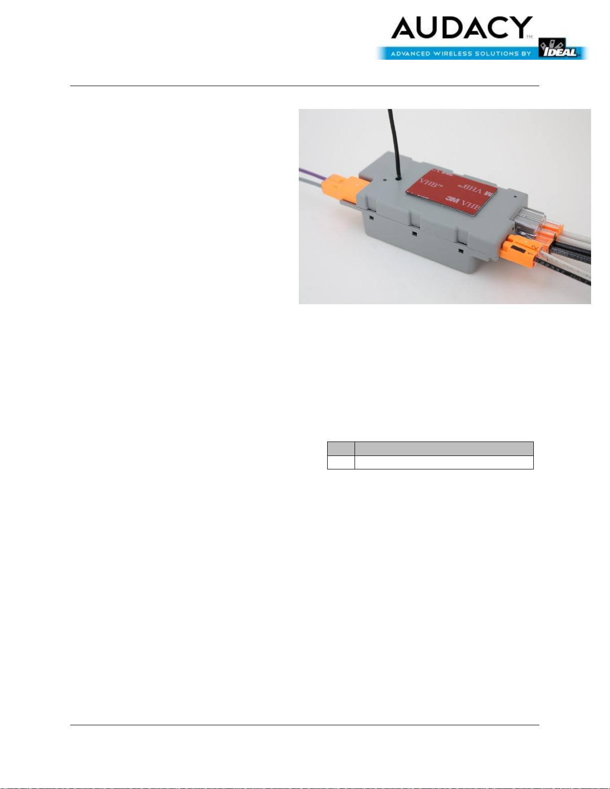
SCC1000 – Smart Connector
PRODUCT DESCRIPTION
The AC Smart Connector is a wireless device
which provides electrical connectivity
between the light fixture (load) and 347V
AC line power and provides on/off power
control and dimming signals to the load.
The information that tells the connector to
power on/off/dim the fixture is acquired via
wireless signals that originate from a
building automation system or from room
controls, based on environmental
conditions and/or predetermined
programs.
KEY FEATURES
FCC and IC approved
Flexible wall mounting options
Small form factor with internal antenna
RoHS compliant
Audacy®, Smart Connector® and Smart Switch® are registered trademarks of IDEAL INDUSTRIES.
All other trademarks are the property of their respective owners.
PRODUCT CONTENTS
The following items are included inside the
package:
ND 7942-1 11/2014 Users Manual – SCC1000 Smart Connector Page 1
www.idealindustries.com
Page 2
Product Manual
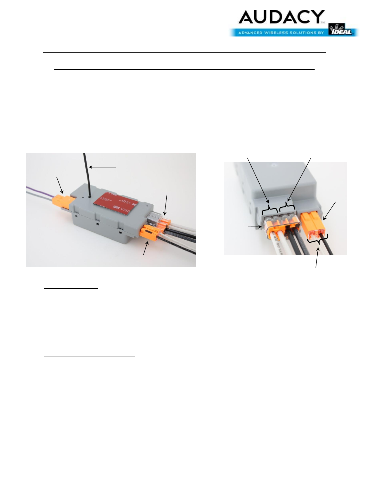
LINE Connector
LOAD
DIM Connector
Fig. 1
Fig. 2
LINE hot & feed-through
LINE neutral & feed-through
LOAD hot (black)
& neutral (white)
Antenna
LINE
Connector
LOAD
Connector
SCC1000 – Smart Connector
IDEAL Model SCL1000 Smart Connector Installation Instructions
WARNING: This is a current rated device. Use in applications involving
amperage beyond its rating can be dangerous and cause electrical fires.
Wiring must comply with all applicable electrical codes.
Turn off power before removing or installing connector.
TERMINOLOGY
LINE: Incoming power feed from premise wiring
LOAD: Power output from Smart Connector to ballast AC power input
DIM: 0-10 VDC dimming control output from Smart Connector to ballast dimming
input
CONNECTING THE WIRES
LINE Connector
The LINE Connector accepts 12 AWG-18 AWG copper conductors, solid or stranded (19
strands or less for 12 AWG-16 AWG, 7 strands or less for 18 AWG).
Use only one conductor per port and ensure that no copper is exposed on any of the
wires after installation.
1. Strip wires to 1/2”.
2. Grip LINE hot wire and firmly push conductor into one of the black LINE ports. See Fig. 2.
3. Grip LINE neutral wire and firmly push conductor into one of the unmarked LINE ports. See
ND 7942-1 11/2014 Users Manual – SCC1000 Smart Connector Page 2
www.idealindustries.com
Page 3

Product Manual
SCC1000 – Smart Connector
Fig. 2.
4. For feed-through (i.e., “daisy-chain”) installations, insert the LINE hot feed-through conductor
into the other black line port. Insert the LINE neutral feed-through conductor into the other
unmarked LINE port. See Fig. 2.
5. After LINE wire installation, the supply power can safely be disconnected and re-connected
without re-installing the wires. To disconnect the supply power, firmly grip the LINE
connector and pull to separate it from the main body of the Smart Connector. To reconnect, simply push the LINE connector into the corresponding port on the Smart
Connector.
LOAD Connector
The LOAD Connector accepts 18 AWG copper conductors, solid or stranded (16 strands
or less).
Use only one conductor per port and ensure that no copper is exposed on any of the
wires after installation.
1. Strip the wires to 3/8”.
2. Grip the LOAD hot wire and firmly push conductor into the port marked with the black stripe.
See Fig. 2.
3. Grip the LOAD neutral wire and firmly push conductor into the unmarked port. See Fig. 2.
4. After LOAD wire installation, the load can safely be disconnected and re-connected without
re-installing the wires. To disconnect the load, firmly grip the LOAD connector and pull to
separate it from the main body of the Smart Connector. To re-connect, simply push the
LOAD connector into the corresponding port on the Smart Connector.
DIM Connector
The DIM Connector accepts 18 AWG copper conductors, solid or stranded (16 strands
or less).
Use only one conductor per port and ensure that no copper is exposed on any of the
wires after installation.
1. Strip wires to 3/8”.
2. Grip positive/(+)/purple DIM conductor and firmly push into the port marked “1”. See Fig. 3.
3. Grip negative/(-)/gray DIM conductor and firmly push into the port marked “2”. See Fig. 3.
4. After DIM wire installation, the DIM connector can safely be disconnected and re-connected
without re-installing the wires. To disconnect the DIM connector, firmly grip the DIM
connector and pull to separate it from the main body of the Smart Connector. To reconnect, simply push the DIM connector into the corresponding port on the Smart
Connector.
ND 7942-1 11/2014 Users Manual – SCC1000 Smart Connector Page 3
www.idealindustries.com
Page 4

Product Manual
Fig. 3
Positive/purple/+ conductor
Negative/gray/- conductor
Fig. 4
SCC1000 – Smart Connector
INSTALLING THE SCL1000 SMART CONNECTOR IN THE FIXTURE
1. After properly installing all wires per the instructions on page 1, fully extend the antenna.
See Fig. 1.
2. Remove the backing of the double-sided tape on the SCL1000, exposing the adhesive.
3. Insert the antenna through an available open hole in the fixture trough, making sure that as
much of the antenna extends into the plenum space above the fixture as possible. See Fig.
4.
4. Firmly press the connector into place.
ND 7942-1 11/2014 Users Manual – SCC1000 Smart Connector Page 4
www.idealindustries.com
Page 5

Product Manual
Item
Description
Radio
915 MHz External Antenna
Regulatory Approvals
FCC Part 15 and Industry Canada
Contains FCC ID: 2AAMXSCC1000
Contains IC: 11250A-SCC1000
UL916
Transmit Range
300 ft. indoors line of sight to an Audacy Gateway or Smart Connector
Load Dimming
0-10VDC (10%-100%)
Load Amperage
5A
Switching Cycles
50,000
Power
347VAC
Operating Temperature
0°C to 70°C
Storage Temperature
-20°C to 90°C
Installation
Environment
Indoor use only
Dimensions
4.67”x1.75”x0.99”
Weight
3.3 oz
Warranty
SCC1000 – Smart Connector
PROGRAMMING
Refer to the Audacy™ system configuration manual to associate smart connectors to other
devices and to set up operating parameters for the Audacy™ lighting control system
SPECIFICATIONS
MECHANICAL DIMENSIONS
ND 7942-1 11/2014 Users Manual – SCC1000 Smart Connector Page 5
www.idealindustries.com
Page 6

Product Manual
SCC1000 – Smart Connector
*Dimensions in inches
ND 7942-1 11/2014 Users Manual – SCC1000 Smart Connector Page 6
www.idealindustries.com
Page 7

Product Manual
SCC1000 – Smart Connector
SUPPORT
Technical support for IDEAL INDUSTRIES products can be initiated through the following
methods:
Website: http://www.idealindustries.com/support/
Telephone: +1 800-435-0705
Email: contactus@idealindustries.com
ND 7942-1 11/2014 Users Manual – SCC1000 Smart Connector Page 7
www.idealindustries.com
Page 8

Product Manual
SCC1000 – Smart Connector
COMPLIANCE STATEMENTS
This device is intended for commercial and industrial applications.
Changes or modifications not expressly approved by IDEAL could void the user’s authority to
operate the equipment. Use and maintain device only as specified in this manual.
This device complies with part 15 of the FCC rules. Operation is subject to the following two
conditions: (1) This device may not cause harmful interference, and (2) this device must
accept any interference received, including interference that may cause undesired operation.
This equipment has been tested and found to comply with the limits for a Class B digital
device, pursuant to Part 15 of the FCC Rules. These limits are designed to provide reasonable
protection against harmful interference in a residential installation. This equipment generates,
uses, and can radiate radio frequency energy and, if not installed and used in accordance with
the instructions, may cause harmful interference to radio communications. However, there is
no guarantee that interference will not occur in a particular installation. If this equipment
does cause harmful interference to radio or television reception, which can be determined by
turning the equipment off and on, the user is encouraged to try to correct the interference by
one of the following measures:
-- Reorient or relocate the receiving antenna.
-- Increase the separation between the equipment and receiver.
-- Connect the equipment into an outlet on a circuit different from that to which the receiver is
connected.
-- Consult the dealer or an experienced radio/TV technician for help.
WARNING!
FCC and IC Radiation Exposure Statement:
This equipment complies with FCC’s and IC’s RF radiation exposure limits set forth for an
uncontrolled environment under the following conditions:
1. This equipment should be installed and operated such that a minimum separation distance
of 20cm is maintained between the radiator (antenna) & user’s/nearby person’s body at all
times.
2. This transmitter must not be co-located or operating in conjunction with any other antenna
or transmitter.
This device complies with Industry Canada licence-exempt RSS standard(s).
Operation is subject to the following two conditions: (1) this device may not cause
interference, and (2) this device must accept any interference, including
interference that may cause undesired operation of the device.
Le présent appareil est conforme aux CNR d'Industrie Canada applicables aux
ND 7942-1 11/2014 Users Manual – SCC1000 Smart Connector Page 8
www.idealindustries.com
Page 9

Product Manual
SCC1000 – Smart Connector
appareils radio exempts de licence. L'exploitation est autorisée aux deux conditions
suivantes : (1) l'appareil ne doit pas produire de brouillage, et (2) l'appareil doit
accepter tout brouillage radioélectrique subi, même si le brouillage est susceptible
d'en compromettre le fonctionnement.
ND 7942-1 11/2014 Users Manual – SCC1000 Smart Connector Page 9
www.idealindustries.com
Page 10

Product Manual
SCC1000 – Smart Connector
IMPORTANT NOTICE
Information furnished by IDEAL INDUSTRIES, INC. is believed to be accurate and reliable. No
license, express or implied, to any intellectual property rights is granted by this document. No
responsibility is assumed by IDEAL INDUSTRIES, INC. for its use, nor for any infringements of
patents or other rights of third parties that may result from its use. IDEAL INDUSTRIES, INC.
assumes no liability for misuse of this product. Specifications are subject to change without
notice.
No license is granted by implication or otherwise under any patent or patent rights of IDEAL
INDUSTRIES, INC. Trademarks and registered trademarks are the property of their respective
owners.
IDEAL INDUSTRIES, INC. PRODUCTS (INCLUDING HARDWARE AND/OR SOFTWARE) ARE NOT
DESIGNED OR INTENDED TO BE FAIL-SAFE, FAULT TOLERANT OR FOR USE IN ANY APPLICATION
THAT COULD LEAD TO DEATH, PERSONAL INJURY OR SEVERE PROPERTY OR ENVIRONMENTAL
DAMAGE (INDIVIDUALLY AND COLLECTIVELY, “CRITICAL APPLICATIONS”), SUCH AS LIFESUPPORT OR SAFETY DEVICES OR SYSTEMS, CLASS III MEDICAL DEVICES, NUCLEAR FACILITIES,
APPLICATIONS THAT AFFECT CONTROL OF A VEHICLE OR AIRCRAFT, APPLICATIONS RELATED
TO THE DEPLOYMENT OF AIRBAGS, OR ANY OTHER CRITICAL APPLICATIONS. CUSTOMER
AGREES, PRIOR TO USING OR DISTRIBUTING ANY SYSTEMS THAT INCORPORATE IDEAL
INDUSTRIES, INC. PRODUCTS, TO THOROUGHLY TEST THE SAME FOR SAFETY PURPOSES.
CUSTOMER ASSUMES THE SOLE RISK AND LIABILITY OF ANY USE OF IDEAL INDUSTRIES, INC.
PRODUCTS IN CRITICAL APPLICATIONS, SUBJECT ONLY TO APPLICABLE LAWS AND
REGULATIONS GOVERNING LIMITATIONS ON PRODUCT LIABILITY.
ND 7942-1 11/2014 Users Manual – SCC1000 Smart Connector Page 10
www.idealindustries.com
Page 11

Product Manual
SCC1000 – Smart Connector
WARRANTY
THIS LIMITED WARRANTY applies solely to standard transmitters manufactured by or on behalf
of IDEAL. Subject to the limitations herein, IDEAL warrants that transmitters, when delivered
by IDEAL or its authorized distributor, for one (1) year following the delivery date, will be free
from defects in material and workmanship and will substantially conform to IDEAL publicly
available specifications for such products in effect at the time of delivery. This limited warranty
excludes: (i) engineering samples (which are provided “AS-IS” without warranty); (ii) bare
circuit boards (iii) development products (such as boards and cables); (iv) design defects or
errors known as “errata”; (v) transmitters procured through unauthorized third parties; and
(vi) transmitters that have been subject to misuse, mishandling, accident, alteration, neglect,
unauthorized repair or installation. Furthermore, this limited warranty shall not apply to the
use of covered products in an application or environment that is not within IDEAL
specifications or in the event of any act, error, neglect or default of Customer. If such IDEAL
products fail to conform to the warranty above, the exclusive remedy of Customer and the
sole liability of IDEAL shall be, at the option of IDEAL, to replace or repair the affected
products, or to refund to Customer the price of the affected products. The availability of
replacement products is subject to product discontinuance policies at IDEAL. Customer may
not return products without first obtaining a customer return material authorization (RMA)
number from IDEAL. THE WARRANTIES SET FORTH HEREIN ARE EXCLUSIVE AND IN LIEU OF ALL
OTHER WARRANTIES, REMEDIES AND CONDITIONS, WHETHER ORAL OR WRITTEN, EXPRESS OR
IMPLIED. IDEAL DISCLAIMS ALL OTHER WARRANTIES, WHETHER EXPRESS, IMPLIED OR
STATUTORY, INCLUDING, WITHOUT LIMITATION, ANY WARRANTY OF MERCHANTABILITY,
FITNESS FOR A PARTICULAR PURPOSE, OR NON-INFRINGEMENT, AND ANY WARRANTY THAT
MAY ARISE FROM COURSE OF DEALING, COURSE OF PERFORMANCE, OR USAGE OF TRADE. IF
IDEAL CANNOT LAWFULLY DISCLAIM IMPLIED WARRANTIES UNDER THIS LIMITED PRODUCT
WARRANTY, ALL SUCH IMPLIED WARRANTIES, INCLUDING WARRANTIES OF MERCHANTABILITY
AND FITNESS FOR A PARTICULAR PURPOSE, ARE LIMITED IN DURATION TO THE WARRANTY
PERIOD (AS DEFINED ABOVE). YOUR SOLE REMEDY WITH RESPECT TO ANY BREACH OF THE
LIMITED PRODUCT WARRANTY SHALL BE THE REPAIR OR REPLACEMENT OF THE DEVICE AS
SPECIFIED IN THE LIMITED PRODUCT WARRANTY. IDEAL IS NOT RESPONSIBLE FOR DIRECT,
SPECIAL, INCIDENTAL, OR CONSEQUENTIAL DAMAGES RESULTING FROM ANY BREACH OF
WARRANTY OR UNDER ANY OTHER LEGAL THEORY INCLUDING, BUT NOT LIMITED TO, LOST
PROFITS, DOWNTIME, GOODWILL, DAMAGE TO OR REPLACEMENT OF EQUIPMENT AND
PROPERTY, AND ANY COSTS OF RECOVERING, REPROGRAMMING, OR REPRODUCING ANY
PROGRAM OR DATA STORED IN OR USED WITH A SYSTEM CONTAINING IDEAL TRANSMITTERS.
Some states do not allow the exclusion or limitation of incidental or consequential damages or
exclusions or limitations on the duration of implied warranties or conditions, so the above
limitations or exclusions may not apply to you. This limited product warranty gives you specific
legal rights, and you may also have other legal rights which vary from state to state.
ND 7942-1 11/2014 Users Manual – SCC1000 Smart Connector Page 11
www.idealindustries.com
 Loading...