

Page 1

Page 2

Response: The combi boiler
The Ideal Response is a wall mounted, fanned flue combination boiler which
serves a home's central heating system and delivers hot water on demand.
It has been designed to be 'friendly' to the user, installer and service engineer.
Response: The fit anywhere combi
Simple fanned 'go anywhere' flue
The Response's flue turret simply rotates through 360° to allow horizontal
outlet in any direction. Options include horizontal flue length extensions
and the flue is self-sealing, eliminating the need for outside assembly - an
important benefit in high-rise applications.
Downward or upward connections...
Water and gas connections have been designed to be as simple and fast
as possible. The Ideal Response comes complete with a rugged mounting
frame which can accommodate downward or upward routed gas, water and
electrical connections before the boiler is fitted.
...and it fits inside a cupboard
Its compact size - up to half that of other combis - makes the Response
ideal for any kitchen. It can be installed inside a standard size kitchen wall
unit without insulation and with minimal ventilation.
Response: The combi you can rely on
The Response has been designed and developed with reliability as the
number one priority. But even the finest engineered product may develop a
fault at some stage in its lifetime. To support the Response we've created
the Ideal Care Guarantee which sets out our target to repair any fault next
day.
Free Guarantee: 1st Y ear Ideal Care
The home owner is entitled to 12 months free Ideal Care, which includes
both parts and labour, to restore the boiler to full function. Please encourage
the home owner to complete and return the registration form in their
Householder's pack within 30 days of installation.
Optional Extra Y ear Cover with Ideal Care
You may wish to offer your own annual service plan or you may wish to
advise the home owner to complete their application form for the appropriate
level of extended Ideal Care - Silver, Gold or Platinum. Full details are available
in the Ideal Care brochure.
CAUTION.
appliance, care should be taken when handling edges of sheet steel components.
T o avoid the possibility of injury during the installation, servicing or cleaning of this
2
Response 80 / 100 / 120
- Installation
Page 3
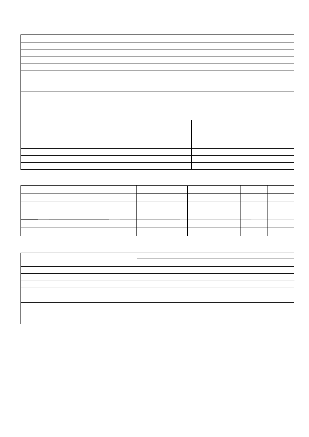
PERFORMANCE DATA
IMPORTANT.
This manual is applicable only to Response boilers with a data plate prefix of RF or above
Table 1 - General Data
Gas supply type & connection 2H-G20-20mbar, 22mm copper
Inlet connection Domestic Hot Water 15mm copper
Outlet connection Domestic Hot Water 15mm copper
Flow & return connection Central heating 22 mm - 28mm copper
Flue terminal diameter mm (in.) 100 (4)
2
Max. working pressure (sealed systems) bar (lb/in
) 2.65 (38.5)
Electrical supply & loading 230 V ~ 50 Hz, 160W max
External fuse rating 3A
Internal fuse rating (BS 42 65) PCB40 F1: 4ATASG PCB40 F2: 2AF HRC PCB41 F1: 2A HRC
Boiler size Height mm (in.) 640 (25 3/16)
Width mm (in.) 436 (17 1/8)
Depth mm (in.) 278 (10 15/16)
Response 80 Response 100 Response 120
o
Average flue temp / mass flow rate 235
C / 11.8 g/s 235 oC / 14.7 g/s 235 oC / 14.7 g/s
Max. DHW water inlet pressure bar (lb/in2) 10.0 (145.0) 10.0 (145.0) 10.0 (145.0)
Min.
DHW water inlet pressure bar (lb/in2) 1.0 (14) 1.2 (17) 1.2 (17)
Dry lift weight kg (lb.) 50 (110) 51.2 (112) 51.2 (112)
Water content Central heating litre (gal.) 1.7 (0.37) 1.7 (0.37) 1.7 (0.37)
Domestic hot water litre (gal.) 0.48 (0.11) 0.7 (0.15) 0.7 (0.15)
Table 2 - Performance Data - CENTRAL HEATING
Max Min Max Min Max Min
Burner pressure (hot) mbar (in.w.g.) 7.2(3.1) 3.5 (1.5) 6.7 (2.6) 1.8 (0.7) 6.7 (2.6) 1.8 (0.7)
Input based on nett CV kW (Btu/h) 19.8
Input based on gross CV kW (Btu/h) 22
Output kW (Btu/h) 17.6
(67500)
(75000)
(60000)
Gas consumption (hot) l/s (ft3/h) 0.568
(72)
12.6
13.9
11.7
0.359
(43000)
(47500)
(40000)
(45)
26.4
29.3
23.4
0.757
(90000)
(100000)
(80000)
(95)
13.2
14.7
11.7
0.380
(45000)
(50000)
(40000)
(48)
26.4
29.3
23.4
0.757
(90000)
(100000)
(80000)
(95.4)
13.2
14.7
11.7
0.380
(45000)
(50000)
(40000)
Table 3 - Performance Data - DOMESTIC HOT WATER
Maximum
Response 80 Response 100 Response 120
Burner pressure (hot) mbar (in.w.g.) 13.2 (5.2) 10.2 (4.0) 13.2 (5.2)
Input based on nett CV kW (Btu/h) 26.4 (90 000) 33 (112 500) 39.7 (135 100)
Input based on gross CV kW (Btu/h) 29.3 (100 000) 36.7 (125 000) 44.0 (150 000)
Output kW (Btu/h) 23.4 (80 000) 29.3 (100 000) 35.2 (120 000)
3
Gas consumption (Hot) l/s (ft
o
Flow 35
C. temp. rise l/m (gpm) 9.6 (2.1) 12.0 (2.6) 14.4 (3.2)
/h) 0.757 (95) 0.95 (120) 1.14 (143)
Domestic hot water specific rate l/m (gpm) 11.2 (2.4) 14.6 (3.2) 17.1 (3.8)
Seasonal efficiency (SEDBUK) * [79.4]% [80.0]% [80.0]%
* The value is used in the UK Government's Standard Assessment Procedure (SAP) for energy rating of dwellings.
The test data from which it has been calculated have been certified by notified body.
(48)
Note.
Gas consumption is calculated using a
calorific value of 38.7 MJ/m3 (1038 Btu/ft3) gross or
34.9 MJ/m3 (935 Btu/ft3) nett
To obtain the gas consumption at a different
calorific value:-
a. FOR L/S - divide the gross heat input (kW) by
the gross C.V. of the gas (MJ/m
3
b. FOR FT
/H - divide the gross heat input (Btu/h)
3
)
by the gross C.V. of the gas (Btu/ft3)
Response 80 / 100 / 120
- Installation
Key to symbols
IE = Ireland GB =United Kingdom (Countries of destination)
PMS = Maximum operating pressure of water
C13,C33 = A room sealed appliance designed for connection via ducts
to a horizontal or vertical terminal which admits fresh air to the
burner and discharges the products of combustion to the outside
through orifices which, in this case, are concentric. The fan is up
stream of the combustion chamber.
= An appliance designed for use on 2nd Family gas, Group H only.
I
2H
3
Page 4

Response 80 (Natural gas) G.C. Appliance No. ........ 47 348 02 B.G. Certified - P.I. No. ........ 87 AS 93
Response 100 (Natural gas) G.C. Appliance No. ........ 47 348 04 B.G. Certified - P.I. No. ........ 87 AT 20
Response 120 (Natural gas) G.C. Appliance No. ........ 47 348 01 B.G. Certified - P.I. No. ........ 87 AS 94
Destination Countries: GB and IE.
Data badge: top RH controls channel
CONTENTS
Air Supply ....................................................................... 7
Boiler Dimensions/Clearances..................................... 6
Boiler Exploded Diagram ............................................ 12
Commissioning and Testing ....................................... 30
Electrical Connections ................................................ 28
Electrical Diagrams..................................................... 28
Electrical Supply Requirements ................................... 9
Extension Ducts - Fitting ............................................. 25
Fault Finding ................................................................. 49
Flow Wiring Diagram ................................................... 28
Flue Fitting
Rear outlet .............................................................. 15
Side outlet .............................................................. 20
INTRODUCTION
Response combi boilers are wall mounted, low water content,
fanned flue combination gas boilers of type C13 intended for use
with gas group I2
Central heating (CH) output modulates between 11.7 kW (40,000
Btu/h) minimum and 23.4 kW (80,000 Btu/h) maximum for
Response 100/120 and 17.6kW (60 000Btu/h) maximum for
Response 80.
Domestic hot water (DHW) output is also fully modulating, with a
maximum of:
Response 80 23.4 kW (80,000 Btu/h)
Response 100 29.3 kW (100,000 Btu/h)
Response 120 35.2 kW (120,000 Btu/h).
The boiler is suitable for connection to fully pumped, pressurised
sealed water systems ONLY.
A system bypass is only required when TRV's are fitted to all
radiators (see Frame 5).
Boilers are supplied fully assembled and, being a 'tube-withintube' design, require no diverter valve or domestic hot water calorifier.
A circulating pump, pressure gauge, safety valve and expansion
vessels for both central heating (CH) and domestic hot water (DHW)
are provided.
H.
Flue Installation Requirements..................................... 8
Gas Safety Regulations................................................. 7
Gas Supply Requirements ............................................ 8
Initial Lighting............................................................... 31
Installation ................................................................... 12
Mandatory Requirements ............................................. 7
Sealed System Requirements...................................... 9
Servicing ...................................................................... 33
Short List of Parts ....................................................... 60
Terminal Guards ............................................................ 8
Thermostatic Radiator valves ...................................... 9
Unpacking .................................................................... 13
Water and Systems ...................................................... 8
Water Connections ...................................................... 6
Water Treatment ........................................................... 9
Wiring Diagrams.......................................................... 28
The CH flow temperature is controlled by an electronic thermostat.
In DHW mode the boiler modulates to sustain a nominal adjustable
water flow temperature of 60
The boiler casing is of white painted mild steel with a drop-down
controls access door.
The boiler temperature control is located behind the controls access
door.
The heat exchanger is made of copper and cast iron.
The system pipework must include drain cocks in appropriate
places. Pipework may be taken downwards or upwards behind
the boiler (using the stand-off channels).
o
C.
OPTIONAL EXTRA KITS
Programmer Kit - fits neatly within the casing. Separate fitting
instructions are included with the kit.
Note.
If using an alternative programmer read Frame 42 first.
Extension Ducts
Roof Flue kit
90o Elbow kit
45o Elbow kit
Powered Vertical Flue kit
Note.
When ordering Pack H or Pack K flue adaptor must
be used.
NOTE TO THE INSTALLER:
LEAVE THESE
INSTRUCTIONS ADJACENT TO THE GAS METER.
ALSO COMPLETE THE BENCHMARK LOG BOOK
AND GIVE THIS TO THE CUSTOMER.
4
Response 80 / 100 / 120
- Installation
Page 5
GENERAL
OPERATION
With no call for CH the boiler fires only when DHW is drawn off.
When there is a call for CH, the heating system is supplied at the
selected temperature until DHW is drawn off. The full output of
the boiler is then directed by the automatic switching off of the
circulation pump to heat the inner coils and supply a maximum
1
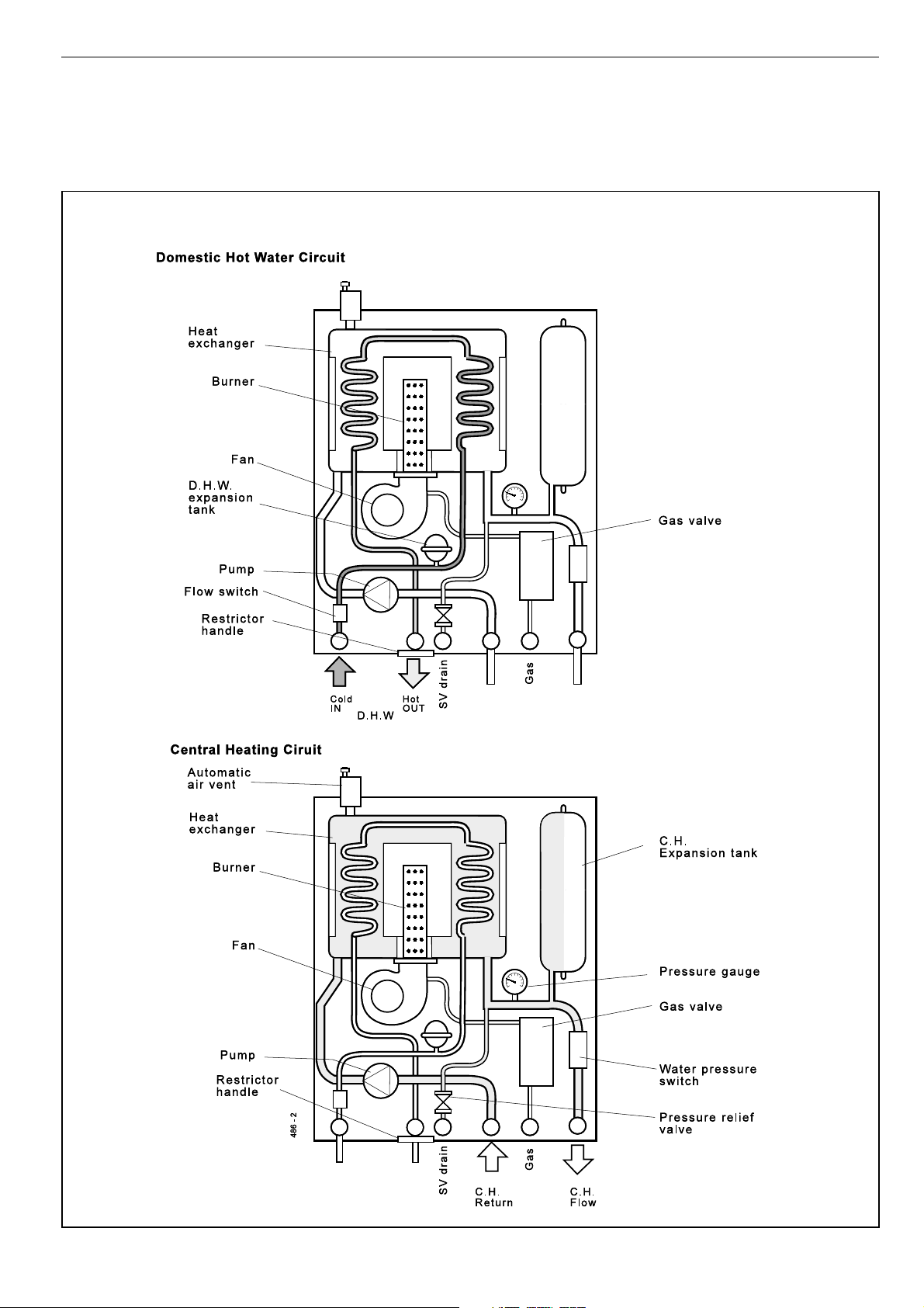
BOILER W ATER CIRCUIT DIAGRAMS
draw-off of :
Response 80 9.6 l/min (2.1 gpm) at 35
Response 100 12.0 l/min (2.6 gpm) at 350 rise
Response 120 14.4 l/min (3.1 gpm) at 35
The nominal DHW temperature is 60 oC but water drawn off
when the boiler has been on for central heating may be hotter
than this, for a short period of time.
0
rise
0
rise.
Response 80 / 100 / 120
- Installation
5
Page 6

GENERAL
2
BOILER DIMENSIONS, SERVICES & CLEARANCES
Boiler connections are made on the mounting frame. Refer to Frame
17.
The following minimum clearances must be
maintained for operation and servicing.
Additional space will be required for installation,
depending upon site conditions.
Side and Rear Flue
a. Provided that the flue hole is cut accurately,
e.g. with a core drill, the flue can be installed
from inside the building where wall
thicknesses do not exceed 600mm (24").
Where the space into which the boiler is
going to be installed is less than the length
of flue required the flue must be fitted from
the outside.
Installation from inside ONL Y
b. If a core boring tool is to be used inside the
building the space in which the boiler is to
be installed must be at least wide enough to
accommodate the tool.
all dimensions in mm (in.)
Front clearance
The minimum front clearance when built in to a
cupboard is 5mm (1/4") from the cupboard door
but 450mm (17 3/4") overall clearance is still
required, with the cupboard door open, to allow
for servicing. See Table 4.
CLEARANCES
Per side 5 mm
Top 160 mm (depth of elbow and lift
Front 450 mm clear of spigot space,
Bottom 150 mm internal wall ring plate)
* Bottom clearance
Bottom clearance after installation can be
reduced to 10mm in an adequately ventilated
enclosed cupboard. However, 150 mm must
be available for servicing.
6
Dimension y
Boiler only with stand-
off brackets
139mm 169mm
7/16") (6 5/8")
(5 (
Distance X is 20mm for DHW pipes and safety valve outlet.
Distance X is 23.5mm for CH pipes and gas inlet.
Response 80 / 100 / 120
- Installation
Page 7

GENERAL
SAFETY
Current Gas Safety (Installation and Use) Regulations
or rules in force.
It is law that all gas appliances are installed and serviced by a
CORGI registered installer in accordance with the above
regulations. Failure to install appliances correctly could lead to
prosecution. It is in your own interest, and that of safety, to
ensure the law is complied with.
The installation of the boiler MUST also be in accordance with
the latest I.E.E (BS.7671) Wiring Regulations, local building
regulations, bye-laws of the local water authority, the building
regulations and the Building Standards (Scotland) and any
relevant requirements of the local authority.
Detailed recommendations are contained in the following
British Standard Codes of Practice:
BS. 5440:1 Flues (for gas appliances of rated input not
exceeding 60 kW).
BS. 5440:2 Ventilation (for gas appliances of rated input not
exceeding 60 kW).
BS. 5449 Forced circulation hot water systems.
BS. 5546 Installation of gas hot water supplies for
domestic purposes (2nd Family Gases)
BS. 6700 Design, installation testing and maintenance of
services supplying hot water for domestic use.
BS. 6798 Installation of gas fired hot water boilers of rated
input not exceeding 60 kW.
BS. 6891 Low pressure installation pipes.
Health & Safety Document No. 635.
The Electricity at Work Regulations, 1989.
The manufacturer’s notes must NOT be taken, in any way, as
overriding statutory obligations.
IMPORTANT. These appliances are CE certificated for safety
and performance. It is, therefore, important that no external
control devices, e.g. flue dampers, economisers etc., are
directly connected to these appliances unless covered by
these Installation and Servicing Instructions or as otherwise
recommended by Caradon Plumbing Limited in writing. If in
doubt please enquire.
Timber Framed Buildings
If the boiler is to be fitted in a timber framed building it should be
fitted in accordance with the Institute of Gas Engineering
document IGE/UP/7:1998.
Bathroom Installations
This range of appliances is rated IP 1XB.
The boiler may be installed in any room or internal space,
although particular attention is drawn to the requirements of the
current I.E.E. (BS.7671) Wiring Regulations and, in Scotland, the
electrical provisions of the building regulations applicable in
Scotland with respect to the installation of the boiler in a room or
internal space containing a bath or shower.
If the appliance is to be installed in a room containing a bath or
shower then, providing water jets are not going to be used for
cleaning purposes (as in communal baths/showers), the
appliance can be installed in Zone 3, as detailed in BS.7671.
Where installation will be in an unusual location, special
procedures may be necessary and BS 6798 gives detailed
guidance on this aspect.
Compartment Installations
A compartment or cupboard, including airing cupboards, must
conform to the following:
! BS. 6798.
! For the minimum clearances required for safety and
subsequent service see the wall mounting template and
Frame 2. In addition, sufficient space will be required to allow
lifting access to the wall mounting plate.
! Ventilation of the compartment ,e.g. permanent high and low
level air vents, must be provided in accord with the current
issue of BS 5440, Part 2. See Table 4 and 'Air Supply' .
T able 4 - Minimum air vent free area for compartments /
cupboards (high and low levels)
Response Vent Air from room or Air direct from
Level internal space outside
80 High/Low 265 (41) 135 (21)
100 High/Low 317 (49) 158 (24)
120 High/Low 396 (62) 203 (32)
2
(in.2 ) - cm2 (in.2 )
- cm
Any direct connection of a control device not approved by
Caradon Plumbing Limited could invalidate the certification
and the normal appliance warranty. It could also infringe the
Gas Safety Regulations and the above regulations.
SAFE HANDLING OF SUBSTANCES
Care should be taken when handling the boiler insulation
panels, which can cause irritation to the skin. No asbestos,
mercury or CFCs are included in any part of the boiler.
LOCATION OF BOILER AND FLUE OUTLET
The boiler must be installed on a flat and vertical wall, capable
of adequately supporting the weight of the boiler and any
ancillary equipment.
The boiler may be fitted on a combustible wall and insulation
between the wall and the boiler is not necessary, unless
required by the local authority.
The boiler must not be fitted outside.
Response 80 / 100 / 120
- Installation
AIR SUPPLY
Detailed recommendations for air supply are given in
BS.5440:2. The following notes are for general guidance:
1. If the boiler is to be installed in a cupboard or compartment,
permanent air vents are required (for cooling purposes) in
the cupboard/compartment at both high and low levels. The
air vents must either communicate with room/internal space
or be direct to outside air. The minimum effective areas of the
permanent air vents required in the cupboard/compartment
are specified in Table 4 and are related to maximum rated
heat input.
2. Both air vents MUST communicate with the same room or
internal space or MUST be on the same wall to outside air.
3. In siting the air vents, care must be taken to avoid the freezing
of pipework.
4. If the boiler is NOT installed in a cupboard or compartment no
air vent is necessary.
7
Page 8

GENERAL
GAS SUPPLY
The local gas supplier should be consulted, at the installation
planning stage, in order to establish the availability of an adequate
supply of gas. An existing service pipe must NOT be used without
prior consultation with the local gas supplier.
A gas meter can only be connected by the local gas supplier or
by a registered CORGI installer.
Check that the appliance is suitable for the proposed gas supply.
A working gas pressure of 20 mbar MUST be available at the
boiler inlet.
IMPORT ANT.
Installation pipes MUST be fitted in accordance with BS. 6891.
Pipework from the meter to Response boilers MUST be of an
adequate size, i.e. not less than 22mm O.D. copper or
3/4" BSP iron.
The complete installation MUST be tested for gas soundness
and purged as described in the above code.
Table 5 - Gas Supply
Total length of supply pipe (metres)
9 121520253540 4550
Gas
Discharge
Note.
160 140 120 100 89 74.2 67.1 63.6 60 22
ft3 / h
330 280 250 210 180 151.9137.7 130.7 123.6 28
Each fitting used in the gas line from the meter is equivalent
to a length of straight pipe which must be added to the straight
pipe length to give the total length. i.e.: bend = 0.5 metres, Tee =
0.5 metres, 90o elbow = 0.3 metres.
Pipe size
(mm Dia.)
FLUE INSTALLATION
The flue must be installed in accordance with the
recommendations of BS. 5440: Part 1.
The following notes are intended for general guidance:
1. The boiler MUST be installed so that the terminal is
exposed to external air.
2. It is important that the position of the terminal allows the
free passage of air across it at all times.
3. Minimum acceptable spacing from the terminal to
obstructions and ventilation openings are specified in
Table 6.
4. Where the lowest part of the terminal is fitted less than 2m
(6'6") above a balcony, above ground or above a flat roof to
which people have access then the terminal MUST be
protected by a purpose designed guard. The minimum
spacing in Table 6, Nos. 2, 3, 4, 5 and 6 would be 75mm, in
order to allow a terminal guard to be fitted.
Terminals guards are available from boiler suppliers - ask
for TFC Guard, Model K1. In case of difficulty contact:
Grasslin (UK) Ltd., Tower House, Vale Rise, Tonbridge,
Kent TN9 1TB. Tel: 01732 359888. Fax: 01732 354445.
www.ffc.ukco.com
Ensure that the guard is fitted centrally.
5. The flue assembly shall be so placed or shielded as to
prevent ignition or damage to any part of any building.
6. The air inlet/products outlet duct and the terminal of the
boiler MUST NOT be closer than 25mm (1") to combustible
material. Detailed recommendations on the protection of
combustible material are given in BS. 5440: 1990.
Table 6 - Balanced flue terminal position
Approved Manufacturer's Clearance
These clearances are for horizontal flue only. For vertical
N.B.
clearances see the publication for Pack K/Pack H.
Note (Positions 2-6)
: Due to the terminal design, installation
is possible with clearances less than those specified in BS
5440, Part 1.
Terminal Position
1. Directly below or alongside an
opening window, air vent or other
ventilation opening 300 mm (12")
2. Below guttering, drain pipes or soil
pipes 25 mm ( 1")
3. Below eaves 25 mm ( 1")
4. Below balconies or a car port roof 25 mm ( 1")
5. From vertical drain pipes or soil pipes 25 mm ( 1")
6. From internal or external corners 25 mm ( 1")
7. Above adjacent ground, roof or
balcony level 300 mm (12")
8. From a surface facing the terminal 600 mm (24")
9. From a terminal facing a terminal 1200 mm (48")
10. From an opening in a car port
(e.g. door or window) into dwelling 1200 mm (48")
11. Vertically from a terminal on the
same wall 1500 mm (60")
12. Horizontally from a terminal on the wall 300 mm (12")
Minimum Spacing
7. Where it is essential that the terminal wall plate
wall thicknesses over 610mm (24") or with an inaccurately
cut hole, the minimum spacing in Table 6, Nos. 2, 3, 4, 5
and 6 would be 60mm (2.4") in order to allow the terminal
wall plate to be fitted.
IMPORTANT. It is the responsibility of the installer to ensure, in
practice, that products of combustion discharging from the
terminal cannot re-enter the building or any other adjacent
building through ventilators, windows, doors, other sources of
natural air infiltration, or forced ventilation / air conditioning.
If this should occur the appliance MUST be turned OFF,
labelled as 'unsafe' until corrective action can be taken.
is fitted, i.e.
FLUE LENGTHS
The flue assembly can be adapted to accommodate flue
lengths up to 3 metres for the 80 and up to 4m for the 100 and
120. Refer to Frame 10.
WATER CIRCULATION SYSTEM
The boilers are designed for connection to pressurised, fully
pumped, sealed water central heating systems ONLY. The
domestic hot water (DHW) calorifier is incorporated within the
heat exchanger and only requires connection to the mains
water supply.
IMPORT ANT.
Copper tubing to BS2871:1 MUST be used throughout the
heating and domestic hot water systems.
8
Response 80 / 100 / 120
- Installation
Page 9

GENERAL
Ensure that the mains water supply pressure is adequate to
provide the required DHW flow rate.
Refer to Table 1 on page 3.
The central heating system should be installed and
commissioned in accordance with BS. 6798 and, in addition,
for smallbore and microbore systems BS. 5449.
The domestic hot water system should be in accordance with
BS. 5546 and BS. 6700.
Any soldered joints on potable water pipework MUST NOT be
made with solder containing lead.
Ancillary pipework not forming part of the useful heating
surface should be lagged to prevent heat loss and any
possible freezing - particularly where pipes run through roof
spaces or ventilated underfloor spaces.
Draining taps should be at least
in accordance with BS 2879.
Maximum recommended system hydraulic losses are given in
the Table within Frame 5.
1/2" BSP nominal size and be
WA TER TREA TMENT
Antifreeze fluid, corrosion and scale inhibitor fluids suitable for
use with boilers having copper heat exchangers may be used
in the central heating system.
For further information contact either:
Fernox Manuf. Co. Ltd or G E Betz Ltd.,
Tandem House Widnes
Marlowe Way Cheshire
Croydon, Surry CRO 4XS
Tel. 0870 601 5000 Tel: 0151 424 5351
THERMOSTATIC RADIATOR VALVES (TRV)
Caradon Plumbing Limited recommend that heating systems
utilising full thermostatic radiator valve control of temperature
in individual rooms should also be fitted with a room
thermostat controlling the temperature in a space served by
radiators not fitted with such a valve as stated in BS. 5449.
When thermostatic radiator valves are used, the space
heating temperature control over a living area having a heating
requirement of at least 10% of the boiler heat output should be
achieved using a room thermostat whilst other rooms are
individually controlled by thermostatic radiator valves.
For further information refer to the 'Good Practice Guide 143', a
publication of the Energy Efficiency Office, available from the
Building Research Establishment, Garston, Watford WD2
7JR. Tel: 01923 664258.
ELECTRICAL SUPPLY
WARNING.
Wiring external to the appliance MUST be in accordance with
the current I.E.E. (BS.7671) Wiring Regulations and any local
regulations which apply.
The point of connection to the mains should be readily
accessible and adjacent to the boiler, except for bathroom
installations where the point of connection to the mains MUST
be situated outside of the bathroom.
Note.
containing a bath or shower then the appliance and any
electrical switch or appliance control utilising mains electricity
should be so situated that it cannot be touched by a person
using the bath or shower.
This appliance must be efficiently earthed.
Where a room sealed appliance is installed in a room
3
SEALED SYSTEM REQUIREMENTS - Central Heating
Note.
Response combination boilers are suitable for
3. Flow Temperature
fully pumped pressurised sealed systems only.
REQUIREMENTS
1. General
Any method of filling, refilling, topping up or flushing
sealed primary hot water circuits from the mains via a
temporary hose connection is only allowed if it complies
with Water Bye-law 14, which states:
" (1) No closed circuit shall be connected to a supply pipe.
(2) Paragraph (1) shall not apply to a temporary connection
provided that:
a. The connection is made through a double check valve
assembly or some other no less effective device which
is permanently connected to that circuit;
and
b. The temporary connection is removed after use. "
The method described in this instruction complies with
that Bye-law.
2. BS. Requirements
The installation must comply with the requirements of
BS. 6891:1988 and BS. 5449.
4. Working Pressure
The installation should be designed to work with flow
temperatures of up to 90° C.
All components of the system must be suitable for a
working pressure of 3 bar (45 lb/in2 ) and temperature of
110°C. Extra care should be taken in making all
connections so that the risk of leakage is minimised.
The following components are incorporated within the
appliance:
a. Circulating pump.
b. Safety valve; with a non-adjustable pre-set lift
pressure of 3 bar (45lb/in
c. Pressure gauge; covering a range of 0-6 bar.
d. 8-litre expansion vessel; with an initial charge
pressure of 1 bar (15 lb/in2).
e. Domestic hot water (DHW) mini expansion vessel.
For further details refer to BS.5449:1 and the British Gas
Corporation publication 'Specifications for Domestic
Central Heating and Hot Water'.
2
).
Response 80 / 100 / 120
- Installation
9
Page 10

GENERAL
4
SEALED SYSTEM REQUIREMENTS - Central Heating - continued
5. Filling the system
Fill the system through a temporary hose connection
from a draw-off tap supplied from a service pipe under
mains pressure. Where the mains pressure is excessive
a pressure reducing valve shall be used to facilitate filling.
The following fittings shall form a permanent part of the
filling system:
A double non-return valve with at least 1 isolation valve,
which is used as a temporary connection to fill the system
from the mains, after which it should be disconnected
and left with the installation.
Proceed with the following:
• Thoroughly flush out the whole of the system with
cold water before fitting the boiler.
• Fill and vent the system until the pressure gauge
registers 1.5 bar (22 lb/in
• Release water from the system until a pressure of
1 bar (15 lb/in
2
) is reached. To avoid getting debris
2
). Examine for leaks.
on the valve seat, do not use the safety valve to do
this.
• Light the boiler and heat the system to the
maximum working temperature. Examine for
leaks.
• Turn off the boiler and drain the system while still
hot.
• Refill and vent the system.
CH Return
(disconnect after filling)
Ecl 6053
6. Size of expansion vessel
For the system water expansion to be contained by the
8-litre expansion vessel fitted to the boiler the cold
system volume must not exceed:
119 litres when pressurised to 0.5 bar (cold)
107 litres when pressurised to 0.7 bar (cold)
91 litres when pressurised to 1.0 bar (cold)
If the pressure exceeds 2.65 bar when the boiler is up
to temperature with all radiators in use then an
additional expansion vessel MUST be installed on the
return pipework.
For expansion volumes see table below.
Hose unions
Temporary hose
Mains
water supply
Additional
stop valve
Double check valve
assembly
(
note direction of flow)
• Re-pressurise the system to the desired charge
pressure (see table below ).
Vessel sizing / Expansion volumes
System charge pressure (bar) 0.5 0.7 1.0
Safety valve setting (bar) 3.0
Vessel pre-charge pressure (bar) 0.5 0.7 1.0
System volume litres V olume of expansion vessel in
75 None None None
100 None None 0.8
125 0.4 1.3 3.0
150 2.1 3.1 5.1
175 3.8 4.1 7.3
200 5.4 6.8 9.5
225 7.1 8.7 11.7
250 8.8 10.5 13.9
275 10.6 12.4 16.1
300 12.2 14.2 18.4
Multiply this factor by system volume and
deduct 8 litres to obtain size of additional 0.067 0.074 0.088
vessel for other system volumes.
Guidance on vessel sizing is given below and also in
BS 7074:1 and BS 5449.
addition to 8-litre unit fitted to boiler
10
Response 80 / 100 / 120
- Installation
Page 11

GENERAL
5
SEALED SYSTEM REQUIREMENTS - Central Heating - continued
7. Thermostatic radiator valves.
Caradon Plumbing Limited support the
recommendations made by leading manufacturers of
domestic heating controls that heating systems utilising
full thermostatic radiator valve control of temperature in
individual rooms should also be fitted with a room
thermostat controlling the temperature in a space served
by radiators not fitted with such a valve. Such an
arrangement will provide for a more efficient control of the
environment and will also avoid the continuous running
of the circulation pump during programmed heating ON
periods, saving electrical energy.
IMPORT ANT.
It is therefore strongly recommended that, when
thermostatic radiator valves are used, the space heating
temperature control over a living/dining area or a hallway,
having a heat requirement of at least 10% of the boiler
output, is achieved using a room thermostat whilst other
rooms are individually controlled by thermostatic radiator
valves.
However, if thermostatic radiator valves are fitted to all
radiators then a bypass MUST be fitted. This should
consist of 22mm (
boiler as possible and incorporating a balancing valve
3/4") pipe positioned as far from the
which cannot be adjusted by the householder.
For adjustment refer to Frame 45.
a. The total length of pipework A, B, C & D
be less than 3m (10') and must not include any other
valves.
b. The balancing valve MUST be at least one turn open.
8. Hydraulic resistance
Having subtracted the hydraulic resistance of the boiler
the head available to overcome system resistance at
MAXIMUM CENTRAL HEATING OUTPUT, with an 11
(20oF) temperature differential, is shown in the table.
MUST NOT
Water Flow Rate and Pressure Loss
Response Response
80 100/120
Max CH Output kW 17.6 23.4
(Btu/h) (60 000) (80 000)
Water flow rate l/sec 0.382 0.508
(gal/min) (5.04) (6.7)
o
Temperature
differential (oF) (20) (20)
Head available for m.w.g. 2.75 2.5
system pump, pos.3 (ft.w.g.) (9.0) (8.0)
9. Draining the system
Draining taps MUST be located in accessible positions
to permit the draining of the whole central heating
system, including the central heating side of the boiler.
The taps should be at least 1/2" BSP nominal size and
be in accordance with BS 2879. The boiler flow and
o
C
return service valves (fitted to the piping frame) have
drain plugs to drain the BOILER ONLY, in the event of
the system drain tap being unable to do so.
C11 11
6
DOMESTIC HOT WATER REQUIREMENTS
1. The domestic hot water service must be in accordance
with BS 5546 and BS 6700.
2. For the minimum and maximum working pressures of
the Response domestic hot water circuit refer to Table
1, page 3.
However in areas where DHW inlet pressures are
greater than 2 bar a water pressure governor should
be fitted to ease commissioning
3. The cold water supply pipe should be flushed before
fitting the boiler.
It is the responsibility of the installer to ensure that the
DHW inlet is free from debris.
4. The boilers are suitable for connection to most types of
washing machine and dishwashing appliances.
5. When connecting to suitable showers, i.e. those
designed for modulating domestic hot water, ensure that:
a. The cold inlet to the boiler is fitted with an approved
anti-vacuum or syphon non-return valve.
b. Hot and cold supplies are of equal pressure.
Response 80 / 100 / 120
- Installation
6. Hard water areas
In areas where the water is 'hard' it is recommended that a
proprietary scale-reducing device is fitted into the boiler
cold supply, within the requirements of the local water
company.
7. DHW Filter
A filter is provided for fitting to the DHW inlet connection.
This filter MUST be fitted in ALL installations.
Refer to the adjoining table for the minimum DYNAMIC inlet
water pressure required to achieve maximum boiler output.
Boiler Water Pressure
Response 80 1.0 bar
Response 100 1.2 bar
Response 120 1.2 bar
11
Page 12

7
INSTALLATION
INST ALLATION
BOILER ASSEMBLY - Exploded View
LEGEND
A. Gas injection pipe.
B. Pressure gauge sub assy.
C. Flue outlet elbow
D. Wall mounting plate
1. Main burner
2. Main burner injector
3. Gas valve
4. Flame sensing electrode
5. Ignition electrode
7. PCB 41
8. PCB 40
9. PCB 8: Fan speed
controller.
12
11. Boiler overheat t'stat.
12. Water pressure switch.
13. DHW O/heat t'stat.
14. DHW sensor.
15. Potentiometer harness.
16. Potentiometer knob
17. Pressure gauge.
19. Fan assembly.
21. Pressure relief valve.
22. DHW expansion vessel
23. CH expansion vessel
24. Pump.
25. DHW Flow switch.
26. Automatic air vent.
27. Heat exchanger.
28. Pressure sensing pip
30. EMC filter.
32. CH Return pipe assy.
33. Pump pipe assy.
34. CH Lower flow pipe assy.
35. CH Upper flow pipe assy.
36. DHW Upper cold pipe assy.
37. DHW Upper hot pipe assy.
38. DHW Lower cold pipe assy.
Response 80 / 100 / 120
39. DHW Lower hot pipe
assy.
40. Boiler front panel.
41. Sealing panel
44. Tank cover assy
45. Controls door assy.
59. Turret clamp.
67. Transformer.
- Installation
Page 13

INST ALLATION
8
UNPACKING
The boiler is supplied fully assembled in one Pack A, together with a standard
flue assembly for lengths up to 600mm, rear or side flue outlet, in Pack B.
Unpack and check the contents.
Pack A Contents
! The boiler.
! These Installation & Servicing Instructions.
! The User's Instructions.
! Wall mounting template.
! Wall mounting frame.
! 1 pair stand-off channels (optional use).
! Flue turret.
! Clamping and sealing ring.
! Mains connector assy.
! Hardware Pack.
! Coupling Hardware Pack.
Hardware Pack
! M6 x 16 Pp. Hd. screw - 4 off.
! 1/2" x 15mm copper connector - 1 off.
! No.14 x 2" slotted Rd. Hd. screw - 6 off.
! Wall plug (brown) - 6 off.
! 1/2" Nut - 2 off.
! M28 Nut - 2 off.
! 22mm pipe connector - 2 off.
! 15mm pipe connector - 2 off.
! 22mm x 15mm reducing coupling - 1 off.
! Pressure relief valve drain pipe - 1 off.
! Pressure relief valve nut - 1off.
! Gas pipe assy. - 1 off.
! 22mm olive - 2 off.
! 15mm olive - 3 off.
! 26mm Sealing washer - 3 off.
! 12mm Sealing washer - 3 off.
INSTALLATION
Pack B Contents
! Terminal grille assembly
! No.8 x 8mm self tapping screw - 3 off
! No.10 x 2" slotted Rd. Hd. screw - 4 off
! Flue support cutting aid - 1 off
! Wall plugs - 4 off
! Terminal wall plate - 1 off
9
PACKAGING AND FRONT PANEL REMOVAL
1. Remove the lid.
2. The top tray contains:
! Flue turret
!"Mounting frame
!" Hardware pack
!" Stand-off channels
!" Wall mounting template
!" Installation instructions
Coupling Hardware Pack.
! 28 x 22 mm straight coupling.
Filter Hardware Pack.
! DHW inlet filter
These contents can be removed, leaving the boiler in its protective package.
Response 80 / 100 / 120
- Installation
13
Page 14
INST ALLATION
10
DETERMINING THE FLUE LENGTH AND FLUE PACKS REQUIRED
USE A MAXIMUM OF 3 EXTENSION DUCTS
ONL Y FOR THE 80 AND A MAXIMUM OF 4
EXTENSION DUCTS FOR THE 100 AND 120.
When using 90o elbow kits, each elbow is
equivalent to 1 metre flue length.
INSTALLATION
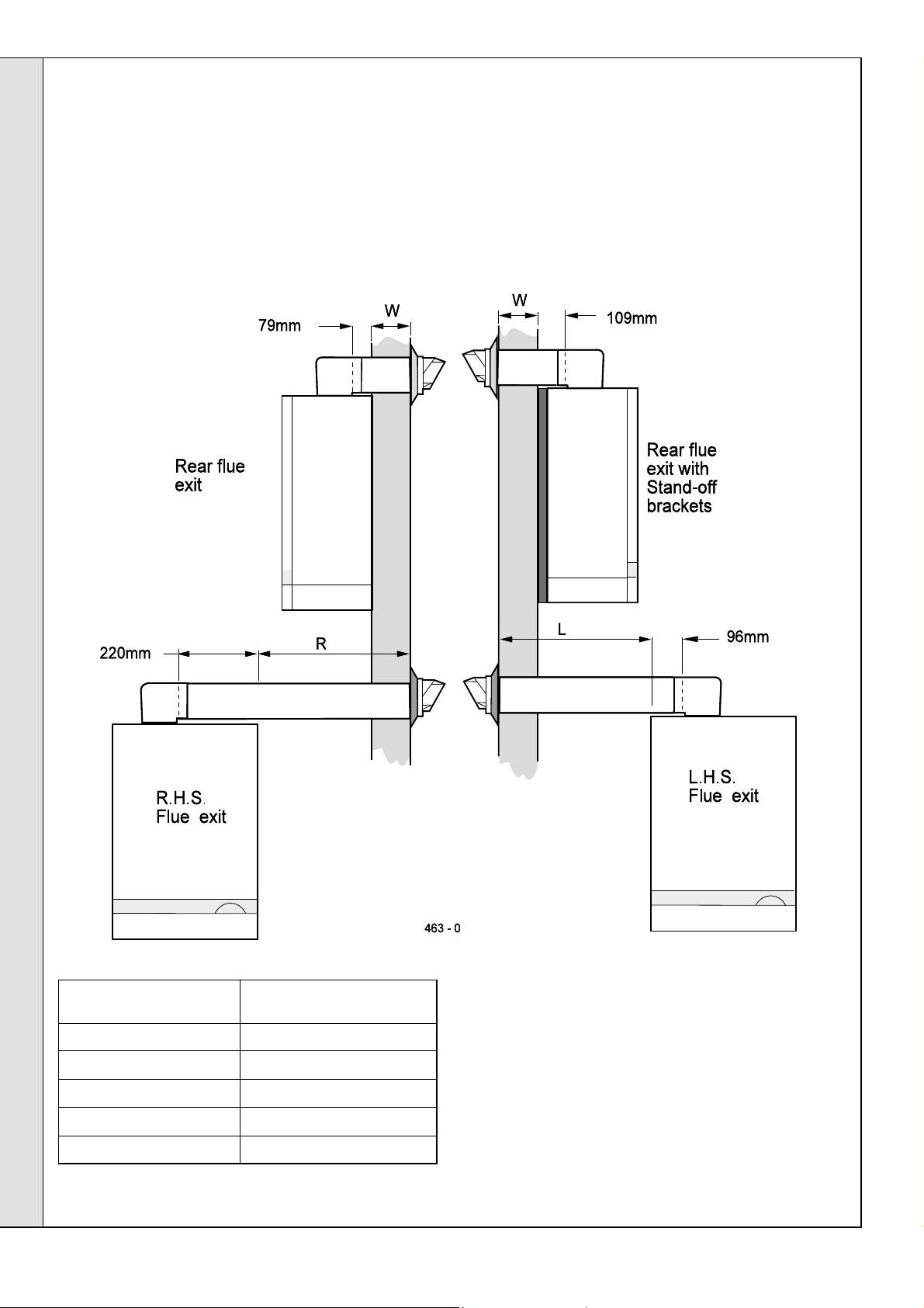
Calculate the total length of flue by the following:
Rear flue length = Dim. W + 79mm (3
Rear flue length with stand-off channels = Dim. W + 109mm (4 3/8")
RHS flue length = Dim. R + 220mm (8
LHS flue length = Dim. L + 96mm (3
Note.
These figures include the length of flue entering the flue turret
socket.
1/8")
5/8")
3/4
")
Flue Kit Requirements
T otal Length of Flue Extra Packs Required
* 600mm (23 5/8") None
*1600mm (63") One Pack D
2600mm (102 3/8") Two Pack D
3000mm (118
4000mm (157
Pack B - supplied as standard.
Pack D - optional extra kit, to extend the flue.
1/8") Three Pack D
1/2") Four Pack D**
14
* N.B.
If the measured flue length is only just above these sizes, it
may be necessary to shorten the standard flue before adding
extension duct(s), in order to prevent interference between
flue duct connections and the boiler flue elbow.
**
4000mm maximum for the 100 and 120 only.
For side flue option
PROCEED TO FRAME 20
Response 80 / 100 / 120
.
- Installation
Page 15

11
REAR FLUE ASSEMBLY - Exploded View
LEGEND
1. Terminal.
2. Weather seal.
3. Duct assembly.
4. Sealing ring.
5. Clamping ring.
6. No.8 x 8 self tapping screw.
7. Flue turret.
8. M5 x 10 pozi Hex screw.
9. Turret clamp.
12
WALL MOUNTING TEMPLATE (Rear Flue)
IMPORTANT.
For direct mounting (wall mounting frame on wall)
choose one black dot in each group.
INST ALLATION
If using the stand-off channels choose one dotted circle
in each group. Care MUST be taken to ensure the
correct holes are drilled.
1. Tape the template into the selected position.
2. Ensure squareness by hanging a plumbline as
shown.
3. Mark onto the wall the following:
a. The 6 wall mounting plate screw positions.
b. The position of the flue duct.
Mark the centre of the hole as well as the circumference.
4. Remove the template from the wall.
13
DRILLING THE W ALL (Rear Flue)
IMPORTANT. Ensure that, during the cutting operation,
masonry falling outside the building does not cause damage
or personal injury.
1. Cut the flue hole (preferably with a 5" core boring tool),
ensuring that the hole is square to the wall.
2. Measure and note the wall thickness 'W'.
3. Drill the 6 fixing holes with an 8mm (
Note.
If the terminal is to be sited within 25-40mm of a
corner or vertical pipe (refer to Table 5) then the hole MUST
be accurately cut and the rubber weather seal trimmed
around the groove provided.
(The terminal wall plate cannot be fitted close to a corner).
Response 80 / 100 / 120
- Installation
5/16") masonry drill.
REAR FLUE OUTLET
15
Page 16

INST ALLATION
14
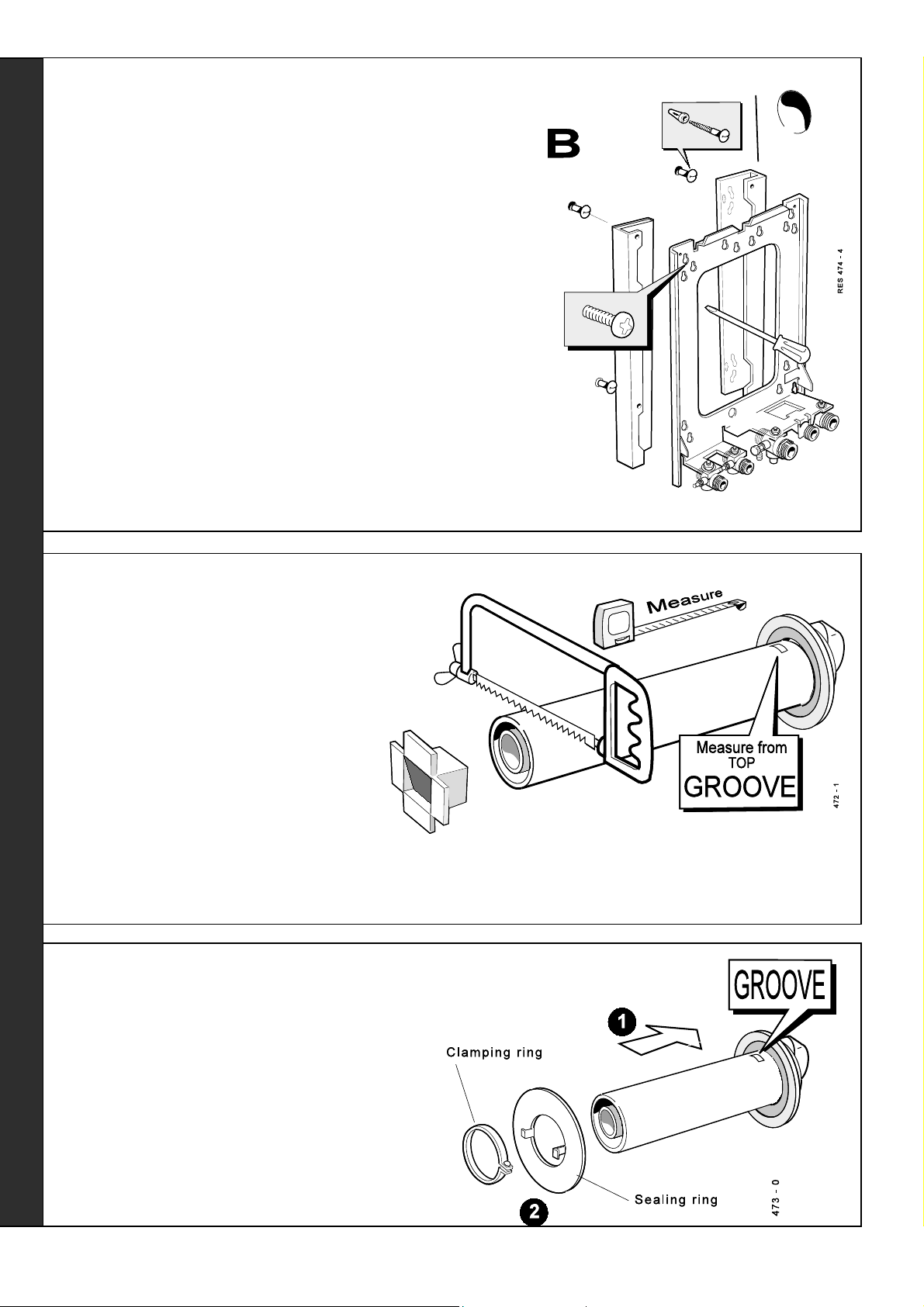
FITTING THE W ALL MOUNTING FRAME
Fit the wall mounting frame either:
a. Directly to the wall
!!
! Insert wall plugs.
!!
!!
! Put the screws into the wall plugs and leave 10mm proud
!!
!!
! Hang the frame onto the screws and tighten up.
!!
or
b. Use stand-off channels
(To allow pipework to be taken upwards).
!!
! Insert wall plugs.
!!
!!
! Put the screws into the wall plugs and leave 10mm proud.
!!
!!
! Fasten each channel to the frame with the 6mm screws
!!
provided.
!!
! Hang the channels and frame onto the screws and tighten
!!
up.
If the clearances above and below the boiler are less
Note.
than the length of the pipes it will be necessary to position the
pipes behind the wall mounting plate BEFORE the plate is
screwed to the wall.
Showing the use of 'stand-off' channels,
to enable upward pipework.
Make service water, gas & electrical connections. Go to Frames 35, 36 & 39 then return to Frame
REAR FLUE OUTLET
15.
16
Response 80 / 100 / 120
- Installation
Page 17

INST ALLATION
15
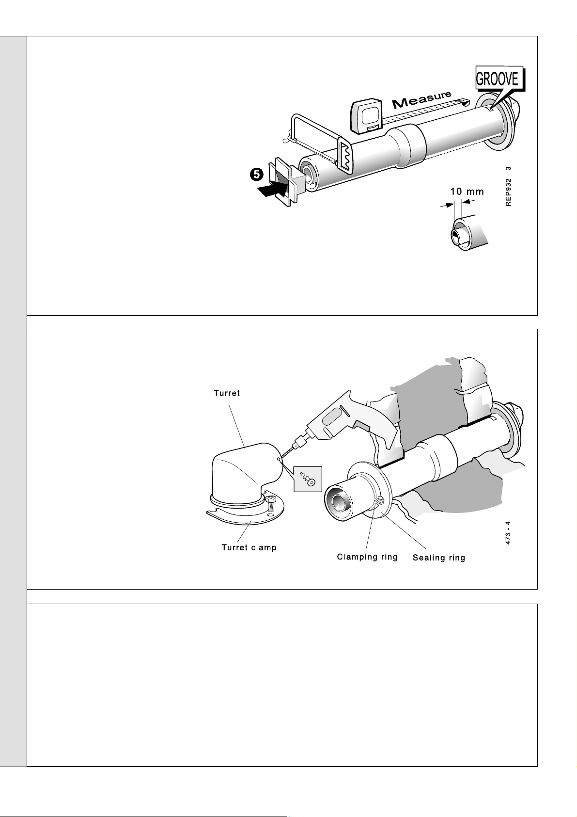
CUTTING THE FLUE - Wall thicknesses up to 600mm (23 5/8")
1. The flue cut length is
calculated as detailed in
Frame 10.
2. Measure from the groove and
mark the tube.
3. To ensure the tube is cut
square, mark the flue all the
way round using (e.g). a long
straight strip of paper with its
ends overlapped.
4. Cut to length, using the
cardboard support aid.
5. Remove the cardboard
support and any burrs.
For flue lengths greater than 600mm (23 5/8") refer to Frames 30 to 32 Flue Extension Ducts
16
FITTING THE FLUE
IMPORTANT
To facilitate turret fixing or removal do NOT make good the wall.
1. Attach the clamping/sealing rings to the flue (this prevents the
assembly being pushed right through the hole and causing an
accident).
2. Pass the cut flue through the prepared hole, ensuring that the
groove is uppermost.
3. Pull the flue back to compress the rubber seal and fix in place
with the clamping/sealing rings.
Response 80 / 100 / 120
- Installation
REAR FLUE OUTLET
17
Page 18

INST ALLATION
17
MOUNTING THE BOILER
1. The boiler may be prewired to the loose electrical
connector and secured with the cable clamps. Refer
to Frame 39.
WARNING. ENSURE
2.
removed from both the DHW and CH pipes before
mounting.
N.B. Some spillage of water may occur from the
pipework when mounting the boiler to the frame.
3. Lift the boiler onto the wall mounting frame, locating it
over the tabs at the top of the frame.
4. Lower the boiler into position.
5. Remove the bottom panel to access service
connections.
6. Fit the filter to the DHW inlet valve,
as shown.
7. Using the correctly sized fibre
washers supplied in the hardware
pack, engage and then tighten the
4 water unions.
8. Engage and tighten the gas union.
9. Fix the pipe and fibre washer to the
safety drain outlet which is supplied
in the boiler hardware pack.
that the plastic plugs are
18
CONNECTING THE TURRET TO THE BOILER
1. Mate the turret to the flue.
2. Secure the flue turret on top of the
boiler by inserting the open ends of
the turret clamp under the 2 studs
and fixing it in the middle with the
single M5 x 10mm pozi-hex screw
provided.
3. Drill a 3.2mm hole through the flue
via the hole already present in the
turret. Secure the turret to the flue,
using the self-tapping screw
provided.
REAR FLUE OUTLET
18
Response 80 / 100 / 120
- Installation
Page 19

INST ALLATION
19
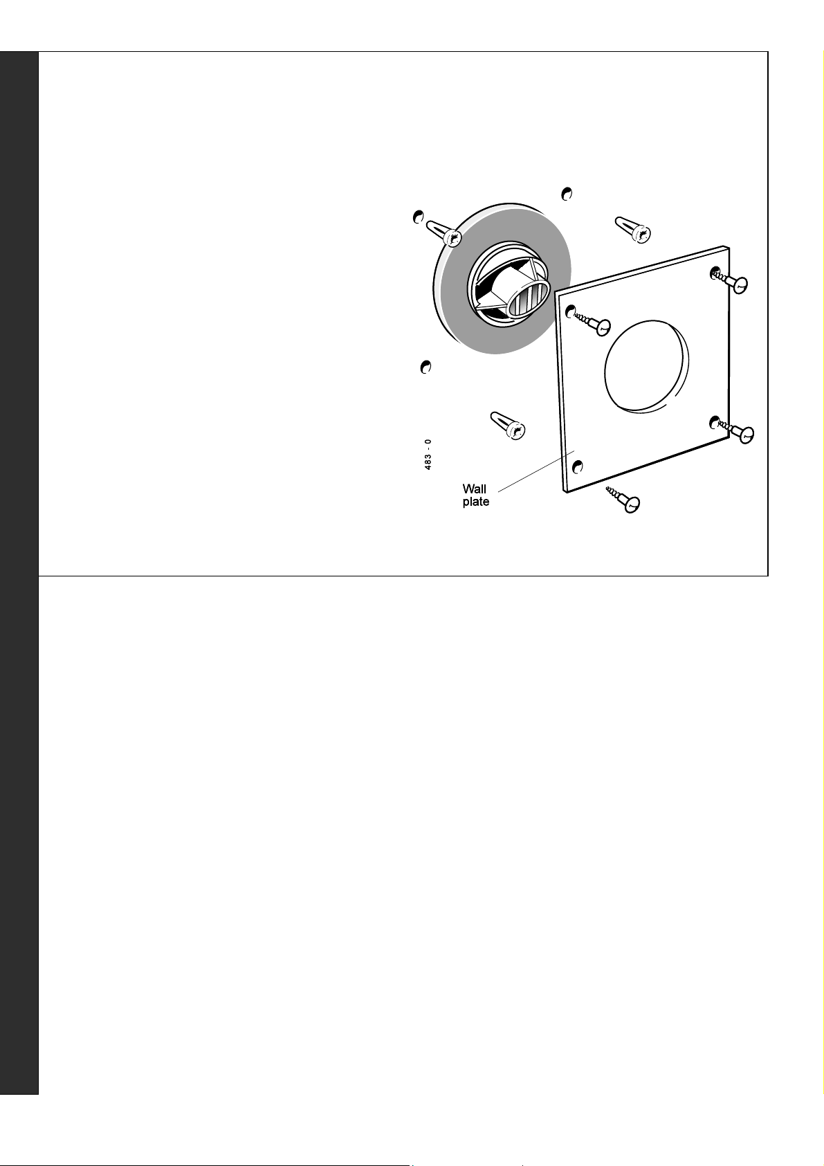
TERMINAL WALL PLATE
This plate allows neat concealment and full
compression of the rubber seal. It should be used,
where practicable::
a. When the wall is more than 24" thick (to support the
flue weight and prevent movement).
or
b. When the hole has not broken through neatly.
or
c. When the wall face is rough and the rubber seal on
its own would be ineffective.
1. Position the terminal wall plate over the terminal.
2. Drill 4 fixing holes with a 7mm (
3. Insert the 4 plastic plugs provided in flue pack B.
4. Secure the plate with 4 of the No.10 x 2" screws provided
in flue pack B.
Note.
If the terminal is less than 2m (6' 6") above ground
level, an approved terminal guard should be fitted.
Refer to 'Flue Installation', Page 7.
1/4") masonry drill.
Response 80 / 100 / 120
- Installation
REAR FLUE OUTLET
19
Page 20

20
SIDE FLUE ASSEMBLY - Exploded View
1. An optional flue duct extension kit is
required for wall thicknesses greater
than:
INST ALLATION
504mm (19
380mm (15") - RHS flue
Refer to Frame 10.
2. When cutting the ducts
always use the cardboard
support cutting aid
provided.
21
WALL MOUNTING TEMPLATE (Side Flue)
IMPORTANT.
For direct mounting (frame on wall) choose one black dot in each group.
If using the stand-off channels choose one circle in each group.
Care MUST be taken to ensure the correct holes are drilled.
7/8") - LHS flue
LEGEND
1. Terminal
2. Weather seal
3. Sealing ring
4. Clamping ring
5. Duct assembly
6. Flue turret
7. Turret clamp
8. M5 x 10 pozi-hex screw
9. No. 8 x 8 fixing screw
Note.
When marking off the flue allow for the
stand-off channels if using them. Read
SIDE FLUE OUTLET
the notes on the template.
1. Tape template into the selected
position.
2. Ensure squareness by hanging
a plumbline, as shown.
3. Mark onto the wall the following:
a. The 6 wall mounting plate
screw positions (choose
one from each group).
b. Extended the centre line as
shown. Mark the flue duct
centre from the corner (see
diagram and template).
Mark the centre of the hole
Note.
as well as the circumference.
4. Remove template from the wall.
20
Response 80 / 100 / 120
- Installation
Page 21

INST ALLATION
22
DRILLING THE W ALL (Side Flue)
IMPORTANT. Ensure that, during the cutting operation,
masonry falling outside the building does not cause
damage or personal injury.
1. Cut the flue hole (preferably with a 5" core
boring tool), ensuring that the hole is square
to the wall.
Both wall faces immediately around the cut
hole should be flat.
2. Measure and note the wall thickness 'W'.
3. Drill 6 holes with an 8mm (
Note.
If the terminal is to be sited within 25-40mm of a corner or vertical pipe (refer to
Table 3) then the hole MUST be accurately cut and the rubber weather seal trimmed
around the groove provided. (The terminal wall plate need not be fitted.)
23
FITTING THE W ALL MOUNTING FRAME
Fit the wall mounting frame, either:
a. Directly to the wall
!!
! Insert the wall plugs.
!!
!!
! Put the screws into the wall plugs and
!!
leave 10mm proud
!!
! Hang the frame onto the screws and
!!
tighten up
5/16") masonry drill.
SIDE FLUE OUTLET
or
Proceed to Frame 24.
Note.
If the clearances above and below the
boiler are less than the length of the pipes it will
be necessary to position the pipes behind the
wall mounting plate BEFORE the plate is
screwed to the wall.
Make service water, gas & electrical connections. Go to Frames 35, 36 & 39 then return to Frame
15.
Response 80 / 100 / 120
- Installation
21
Page 22
INST ALLATION
24
FITTING THE WALL MOUNTING FRAME - continued
or
b. Use stand-off channels
(To allow pipework to be taken upwards).
!!
! Insert the wall plugs.
!!
!!
! Put the screws into the wall plugs and leave 10mm
!!
proud.
!!
! Fasten each channel to the frame with the 6mm
!!
screws provided.
!!
! Hang channels and frame onto the screws and
!!
tighten up.
If the clearances above and below the boiler are less
Note.
than the length of the pipes it will be necessary to position
the pipes behind the wall mounting plate BEFORE the
plate is screwed to the wall.
Make service water, gas & electrical connections. Go to Frames 35, 36 & 39 then return to Frame
15.
25
CUTTING THE FLUE TO LENGTH
Flues up to 600mm (23 5/8")
1. The flue cut length is calculated as detailed
in Frame 10.
2. Measure from the groove and mark the tube.
3. To ensure the tube is cut square, mark the
SIDE FLUE OUTLET
flue all the way round, using, e.g. a long
straight strip of paper with its ends
overlapped.
4. Cut to length, using the cardboard support
aid.
5. Remove the cardboard support and any
burrs.
For flue lengths greater than 600mm refer to Frames 30 to 32 - Flue Extension
Ducts
26
FITTING THE FLUE
1. Attach the clamping/sealing rings to the flue (this
prevents the assembly being pushed right through the
hole and causing an accident).
2. Pass the cut flue through the prepared hole, ensuring
that the groove is uppermost.
3. Pull the flue back to compress the rubber seal and fix
in place with the clamping/sealing rings.
Note.
To facilitate turret fixing or removal do NOT make good the
wall.
22
Response 80 / 100 / 120
- Installation
Page 23

27
MOUNTING THE BOILER
1. The boiler may be prewired to the loose
electrical connector and secured with the
cable clamps. Refer to Frame 39.
2. WARNING. Ensure that the plastic plugs are
removed from both the DHW and CH pipes
before mounting.
N.B. Some spillage of water may occur from
the pipework when mounting the boiler to the
frame.
3. Lift the boiler onto the wall mounting frame,
locating it over the tabs at the top of the frame.
4. Lower the boiler into position.
5. Remove the bottom panel to access service
connections.
6. Fit the filter to the DHW inlet valve, as shown.
7. Using the correctly sized fibre washers
supplied in the hardware pack, engage and
then tighten the 4 water unions.
INST ALLATION
8. Engage and tighten the gas union.
9. Fix the pipe and fibre washer to the safety
drain outlet which is supplied in the boiler
hardware pack.
28
CONNECTING THE TURRET TO THE BOILER
1. Mate the turret to the flue.
2. Secure the flue turret on top of the boiler by inserting the
open ends of the turret clamp under the 2 studs and
fixing it in the middle with the single M5 x 10mm pozi-hex
screw provided.
3. Drill a 3.2mm hole through the flue via the hole already
present in the turret. Secure the turret to the flue, using
the self tapping screw provided.
SIDE FLUE OUTLET
4. Flues over 1 metre long
Fix the flue support bracket
to the wall, using the wall
plug and wood screw.
• For standard
installations use the
short wood screw.
• If the 'stand-off' option
is used secure the
support bracket, using
the spacer bracket and
long wood screw.
Response 80 / 100 / 120
- Installation
23
Page 24
INST ALLATION
29
TERMINAL WALL PLATE
This plate allows neat concealment and full compression of
the rubber seal. It should be used (where practicable):
a. When the wall is more than 24" thick (to support the flue
weight and prevent movement).
or
b. When the hole has not broken through neatly.
or
c. When the wall face is rough and the rubber seal on its
own would be ineffective.
1. Position the terminal wall plate over the terminal.
2. Drill 4 fixing holes with a 7mm (
3. Insert the 4 plastic plugs provided in flue pack B.
4. Secure the plate with 4 of the No.10 x 2" screws provided
in flue pack B.
If the terminal is less than 2m (6' 6") above ground
Note.
level, an approved terminal guard should be fitted.
Refer to 'Flue Installation', Page 7.
1/4") masonry drill.
SIDE FLUE OUTLET
24
Response 80 / 100 / 120
- Installation
Page 25

INST ALLATION
30
FLUE EXTENSION DUCT PACK D CONTENTS
Use a maximum of 3 extension ducts only for the 80 and a maximum of 4 extension
ducts for the 100 and 120.
31
ASSEMBLING THE EXTENDED FLUE
INSTALLATION
1. Remove the cardboard support aid from the
flue and place safely to one side.
2. Fit the inner flue extension duct onto the
inner flue duct.
3. Fit the outer flue extension duct onto the
outer air duct.
4. Drill one 3.2mm (
outer air duct.
duct.
5. Insert the self tapping screw provided to fix
the air duct in position.
6. Repeat steps 1-5 if a second flue extension
is required.
1/8") dia. hole through the
Do not drill the inner flue
Response 80 / 100 / 120
- Installation
25
Page 26
32
CUTTING THE FLUE TO LENGTH
1. Check the flue length measurement made in
Frame 10.
2. Use this dimension to mark the flue length,
starting from the groove, as illustrated.
3. To ensure a square cut, mark the flue all the
way round, using, e.g. a steel tape or paper
strip with the ends overlapped.
4. Cut to length, using the cardboard support aid.
5. Remove the cardboard offcuts and de-burr the
INSTALLATION
metal edges.
6. Mark round the air duct 10mm from the end.
7. Cut air duct only to be 10mm shorter than the
flue duct to allow for the engagement.
8. Clean and de-burr ends of ducts.
INST ALLATION
33
FIXING THE FLUE TO THE TURRET
1. Insert the flue into the prepared
hole. Refer to Frame 26 for details.
2. Mate the flue to the turret. Refer to
Frame 28 for details.
Note.
To facilitate turret fixing or removal do
NOT make good the wall.
34
SERVICE CONNECTIONS
General Notes
1. As detailed in Frames 14 and 23/24 'Fitting the Wall
Mounting Frame', top entry pipework is an option, as well
as mounting from the bottom or through the wall.
If pipes are run vertically within the boiler back space
provided by optional stand-off channel positions they must
avoid any obstructions imposed by the channels and by a
rear facing flue, should this position be selected.
26
2. Horizontal connecting pipes, where used, must be run
outside the limits of the boiler casing.
Response 80 / 100 / 120
- Installation
Page 27

35
WATER CONNECTIONS
Refer to General Note, Frame 34, for guidance.
Note.
Do not subject any of the isolating valves to heat as the
seals may be damaged .
CH CONNECTIONS
INST ALLATION
For central heating loads greater than 60 000 BTU's the
flow and return circuits should be increase to 28mm pipe
diameter immediately upon leaving the boiler with the
fitting supplied.
DHW CONNECTIONS
INSTALLATION
For top connections: reverse 22mm pipe.
36
GAS CONNECTION
Refer to General Note, Frame 34, for guidance.
Bottom connection
1a. Solder the 1/2" connector and reducing coupling to the preformed
pipe provided
T op connection
1b. Solder the 1/2" connector and reducing coupling to the preformed
pipe provided.
OR
For top connections:
use 15mm straight pipe and elbow (not supplied).
Bottom and T op connections
2. Remove the gas cock bracket complete with gas cock.
3. Screw connector into gas cock in the correct orientation.
4. Screw complete assembly back onto the mounting frame.
Extend a gas supply pipe of not less than 22mm O.D. copper or 3/
4" BSP iron to the boiler.
A working gas pressure of 20mbar (8" w.g.) must be available at
the boiler inlet with the boiler firing at full DHW output.
IMPORTANT. Ensure the gas supply pipework is adequate - see Table 5 page 8.
37
SAFETY V ALVE DRAIN
The discharge pipe should be positioned so that the discharge of water or steam cannot create a
hazard to the occupants of the premises or damage to electrical components and wiring.
Response 80 / 100 / 120
- Installation
27
Page 28
INST ALLATION
38
ELECTRICAL CONNECTIONS
WARNING.
A mains supply of 230 V ~ 50 Hz is required.
The fuse rating should be 3 A.
All external controls and wiring MUST be suitable for mains
voltage. Wiring should be 3 core PVC insulated flexible cord
NOT LESS than 0.75 mm
Table 16.
not electrical - reasons.)
INSTALLATION
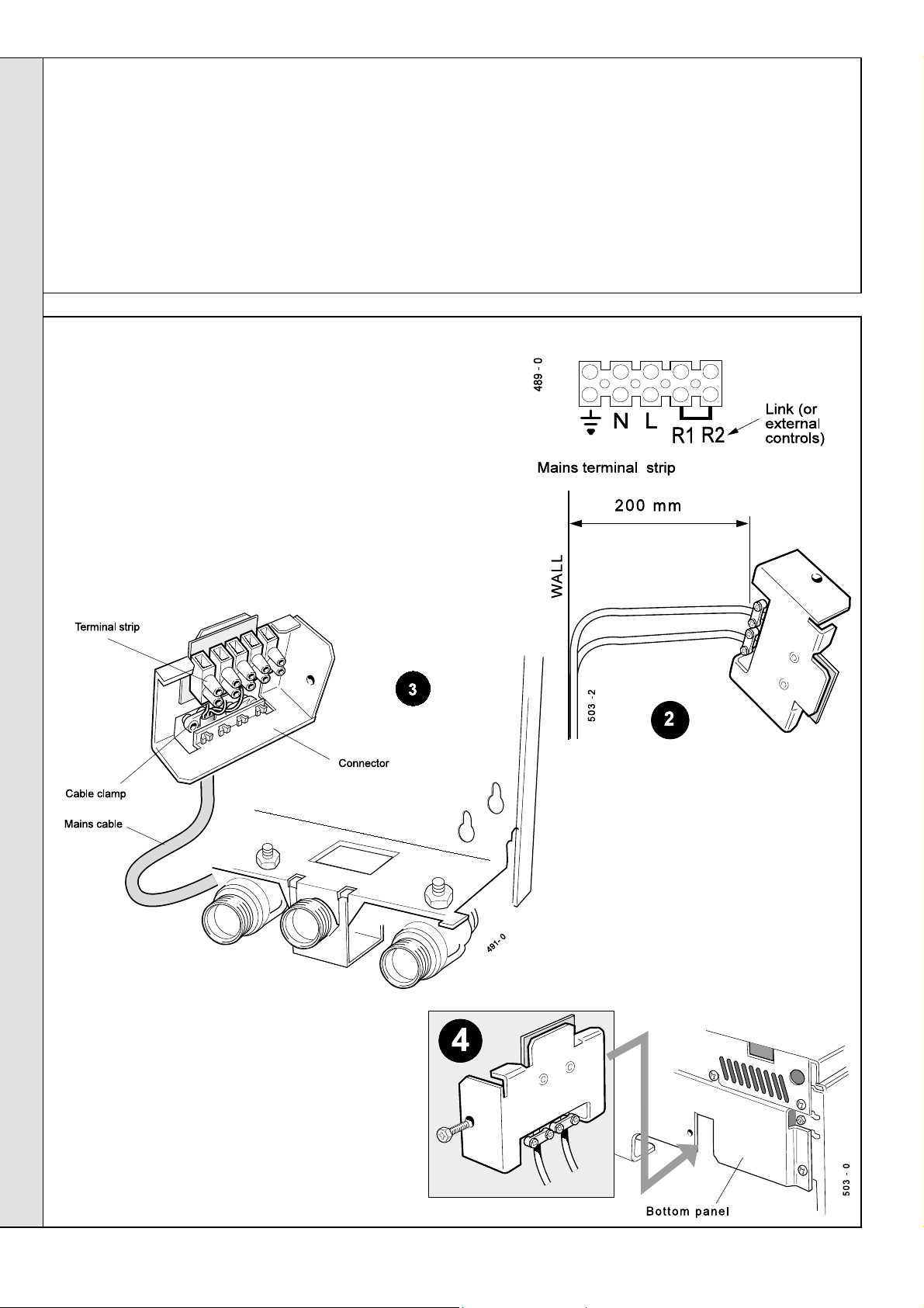
39
Note.
instructions provided with the kit, and Frame 40.
A pictorial wiring diagram is shown in Frame 40.
1. Ensure a length of 200mm between the wall and the connector. Fix the
cable(s) to the mounting frame with the clamp(s).
2. Wire the mains cable into the connector terminal strip (supplied in the
hardware pack).
This appliance MUST be efficiently earthed
2
(24 x 0.2mm) and to BS. 6500,
(0.5mm2 flex is NOT acceptable - for mechanical,
INTERNAL WIRING
If the programmer kit is to be fitted, refer to the
Wiring external to the boiler MUST be in accordance with
the current I.E.E. (BS7671) Wiring Regulations and any
local regulations.
Connection must be made in a way that allows complete
isolation of the electrical supply - such as a double pole
switch, having a 3mm (1/8") contact separation in both
poles, or a plug and socket serving only the boiler and
system controls.
The means of isolation must be accessible to the user after
installation.
Incoming mains wiring detail
3. Offer the connector to its mating half inside the boiler. Secure the
connector to the panel with the screw.
28
Note.
Ensure that the lengths of
the current conductors are shorter
than the earth conductor so that if
the cable slips in its anchorage
the current carrying conductors
become taut before the earth
conductor.
Response 80 / 100 / 120
- Installation
Page 29

40
PICTORIAL WIRING
INSTALLATION
INSTALLATION
LEGEND
b-blue
bk - black
41
FUNCTIONAL FLOW WIRING DIAGRAM
LEGEND
b-blue
bk - black
br - brown
gy - grey
or - orange
pk - pink
r-red
v-violet
w-white
y-yellow
y/g - yellow/green
RES 6093
br - brown
gy - grey
or - orange
pk - pink
r-red
v-violet
w-white
y-yellow
y/g - yellow/green
v
v
PCB 40
PCB 41
Response 80 / 100 / 120
- Installation
29
Page 30

INST ALLATION
42
EXTERNAL ELECTRICAL CONTROLS
Wiring External to the Boiler
WARNING
A mains supply of 230 V ~ 50 Hz is required.
The fuse rating should be 3A.
Wiring external to the boiler MUST be in accordance with the current
I.E.E. (BS.7671) Wiring Regulations and any local regulations.
All external controls and wiring must be suitable for mains voltage.
Wiring should be 3 core PVC insulated cable, not less than 0.75 mm
x 0.2mm).
. This appliance must be efficiently earthed.
INSTALLATION
Wiring external to the boiler MUST be in accordance with the current
wiring regulations and any local regulations.
Connection must be made in a way that allows complete isolation of the
electrical supply such as a double pole switch having a 3mm (1/8")
contact separation in both poles, or a plug and socket, serving only the
boiler and system controls. The means of isolation must be accessible
to the user after installation.
Internal Programmer
The Ideal Programmer Kit is supplied with its own instructions.
Associated controls should be wired as shown in Diagram A.
Earths are not shown for clarity but must never be omitted.
2
(24
External Single Channel Programmer
This should be wired as shown in Diagram B
External T wo Channel Programmer
This should be wired as shown in Diagram C. The power to the
programmer should be isolated with the same switch that isolates power
to the boiler, otherwise the boiler can be left live, even when the boiler
isolating switch is off. Using a two channel programmer will disable the
heating switch.
Room Thermostat
It is recommended to use a room thermostat in conjunction with the
boiler to give the most efficient boiler performance and the most
comfortable central heating performance. The room thermostat
should be wired (depending on the programmer option) as either
diagram A, B or C. The boiler will operate without a room thermostat
by using the central heating temperature control to vary the flow
temperature between 70 oC and 82 oC (± 5 oC.)
Frost Thermostat
Central heating systems fitted wholly inside the house do not normally
require frost protection as the house acts as a 'storage heater' and
can normally be left at least 24 hours without frost damage.
43
COMMISSIONING AND TESTING
These diagrams are schematic only
N.B.
and do not show external terminal strips etc.
However, if parts of the pipework run outside the house
or if the boiler will be left off for more than a day or so
then a frost thermostat should be wired into the system.
The frost thermostat should be sited in a cold place but
where it can sense heat from the system.
Wiring should be as shown.
Note. If
necessary to fit a pipe thermostat, preferably on the
return pipework.
the boiler is installed in a garage it may be
A. ELECTRICAL INSTALLATION
1. Checks to ensure electrical safety should be carried out by
a competent person.
2. ALWAYS carry out the preliminary electrical system checks,
i.e. earth continuity, POLARITY, resistance to earth and short
circuit, using a suitable test meter.
WARNING
doors, extinguish naked lights and DO NOT SMOKE.
.
Whilst effecting the required gas soundness test and purging air from the gas installation, open all windows and
30
B. GAS INSTALLATION
The whole of the gas installation, including the meter, should
be inspected and tested for soundness and purged in
accordance with the recommendations of BS. 6891.
i.e. not less than 5 times the capacity per revolution of the gas
meter mechanism.
Response 80 / 100 / 120
- Installation
Page 31

44
INITIAL LIGHTING
INST ALLATION
The illustration is shown with the control door removed.
LEGEND
A 'Mains on' neon.
B 'Burner on' neon.
C Boiler (on/off) switch.
D Heating switch.
IMPORT ANT.
Before lighting the boiler you should note especially that:
a. To extract maximum heat from the boiler, a 2 minute
pump overrun period occurs after each heating cycle
(unless immediately followed by DHW draw off).
b. During this period the boiler
even if the room thermostat is calling - this prevents
short cycling and thus is more efficient.
c. The 2 minute period can be curtailed by running a hot
tap for a few seconds or turning the mains off briefly.
d. At the end of each period of DHW draw-off the pump
will run for few seconds, to extract the residual heat
from the heat exchanger.
E Burner pressure test point.
F Signal pressure test point (Lo).
G Signal pressure test point (Hi)-fan.
H Overheat thermostat reset button.
will not restart for CH
The illustration is shown with the control & front panel removed.
J Gas service cock.
K Heating control knob.
L Pressure gauge.
M Programmer display (optional).
6. Check that the gas service cock (J) is ON.
7. Switch the electricity supply ON and check that all external
controls are calling for heat.
,
8. Set the boiler (on/off) switch (C) and the heating switch (D)
to 'ON'. Following a pre-purge period the gas control
solenoid valve should open and the spark commence,
continuing until the burner is established.
9. Check that the burner lights smoothly and that the 'Burner
on' neon (B) illuminates. The boiler will attempt 4
ignitions. If the burner does not light after the 4 attempts,
turn the on/off switch to OFF, wait for 5 seconds then try
again. If the burner still does not light refer to the 'Fault
Finding' section.
INSTALLATION
e. Provided that the mains supply switches are left ON,
the pump will run for at least 30 seconds each day
(even if neither CH nor DHW is in use), as a selfchecking measure.
1. Check that all the drain cocks are closed and any valves
in the flow and return are open. Open the dust cap on the
auto air vent (see Frame 1) by one turn.
2. Check that the system has been filled and pressurised
(see Frame 4) and that the boiler is not air locked.
3. Check that the overheat thermostat (H) is calling for heat -
press the reset button.
4. Remove boiler front panel. Refer to Frame 48.
5. Remove the screw in the burner pressure test point (E) -
located behind the lower front panel - and connect a gas
pressure gauge via a flexible tube.
Be sure to select the correct pressure test point. Refer to
Tables 2 & 3 on page 3 for pressures.
10.Test for gas soundness around ALL boiler gas
components, using leak detection fluid.
11. Operate the boiler for 10 minutes to stabilise the burner
temperature.
12.The burner pressure is regulated by the gas valve
according to the air flow produced by the fan.
user-adjustable
the gas valve will adversely affect operation and render
our warranty void.
However you should check that the inlet pressure (see
Frame 36) is at least 20 mbar when the boiler is firing.
13.Set the boiler (on/off) switch (C) to OFF.
14.Remove the pressure gauge and tube. Replace the
sealing screw in the pressure test point. Ensure a gas
tight seal is made.
15.Refit the boiler front panel, using the screw previously
removed.
16.Switch the boiler on again.
. Any interference to sealed settings on
It is NOT
Response 80 / 100 / 120
- Installation
31
Page 32

INST ALLATION
45
GENERAL CHECKS
Make the following checks for correct operation:
1. Hot water
a. Fully open all DHW taps in turn and ensure that water
flows freely from them.
b. Close all taps except the furthest one from the boiler
and check that the boiler is firing at maximum rate.
c. Check DHW flow rate and ADJUST to requirements
with boiler cold.
To obtain best overall summer and winter water
temperature and flow Caradon recommend setting at
a temperature rise = 40oC . See Table below.
d. Turn off the DHW tap.
INSTALLATION
Model Flow rate litres/min. Time to fill a standard
o
C Temp rise 40oC Temp rise 2 gallon bucket
35
80 9.6 8.4 65 secs
100 12.0 10.5 52 secs
120 14.2 12.6 43 secs
2. Central heating
Operate each control separately and check that the main
burner or circulating pump, as the case may be,
responds.
3. Gas rate
Check the boiler gas rate when the boiler is at full DHW
output. The gas rate will normally be between:
Response 80 43.1 to 47.7 litres per minute
1.52 to 1.68 cu/ft per minute
Response 100 51.9 to 57.4 litres per minute
1.8 to 2.0 cu/ft per minute
Response 120 64.8 to 71.6 litres per minute
2.28 to 2.52 cu/ft per minute
checked at the gas meter, with no other appliance in use.
These figures apply at the nominal UK mains voltage of
230V.
Note.
Long flue will reduce air flow, reducing the gas rate,
slightly. If these rates are not obtainable consult the fault
finding section.
4. Water circulation system
Note.
Fernox Superfloc flushing solution should be used
during the flushing procedure.
a. With the system HOT examine all water connections
for soundness.
b. With the system still HOT, turn off the gas, water and
electricity supplies to the boiler and drain down, to
complete the flushing process.
c. Refill the system, adding inhibitor (see 'Water
Treatment'), if required.
Vent as necessary to clear all air and, again, check for
water soundness. After venting, repressurise as
required.
d. Balance the system.
It is suggested that, initially, all
radiator handwheel valves (or TRVs if fitted) be
set fully open, that all lockshield valves be set a
half-turn open and the bypass a half-turn to one
turn open (a minimum of one turn open is
recommended when TRVs are used.)
Make minor adjustments to each radiator to achieve
the same differential on all.
Lastly, set the bypass to eliminate any boiler noise,
without compromising radiator temperatures.
5. Finally, set the system controls to the user’s requirements.
6. Remove the labels from the casing front panel.
If an optional programmer kit is fitted refer to the
instructions supplied with the kit.
46
HANDING OVER
After completing the installation and commissioning
of the system, the installer should hand over to the
householder by the following actions:
1. Hand the User's Instructions to the householder and
explain his or her responsibilities under
Safety (Installation and Use) Regulations, or rules in
force.
2. Draw attention to the Lighting Instruction label affixed to
the inside of the lower front door.
3. Explain and demonstrate the lighting and shutting down
procedures.
4. The operation of the boiler and the use and adjustment of
ALL system controls should be fully explained to the
householder, to ensure the greatest possible fuel
economy consistent with household requirements of both
heating and hot water consumption.
5. Advise the user of the precautions necessary to prevent
damage to the system and to the building, in the event of
the system remaining inoperative during frosty conditions.
current Gas
32
6. If a programmer kit is fitted, draw attention to the
Programmer Kit User's Instructions and hand them to the
householder.
7. After installation, commissioning and customer hand-over
instructions please complete the
book and leave this with the customer.
8. Stress the importance of regular servicing by a CORGI
registered installer and that a comprehensive service
should be carried out AT LEAST ONCE A YEAR.
9. Demonstrate how to repressurise the boiler when the
system pressure falls below 0.5 bar.
Emphasise to the user that the boiler may stop
10.
appliance log
working if the system pressure is lowered by draining
radiators to decorate behind them. In particular, explain
to the user how the domestic hot water temperature
varies with flow rate. This is especially important when
water is drawn off while the boiler is already running for
central heating (refer to 'CAUTION' in User's
Instructions, page 2).
Response 80 / 100 / 120
- Installation
Page 33

SERVICING
47
SERVICING SCHEDULE
To ensure the continued safe and efficient operation of the
appliance it is recommended that it is checked at regular
intervals and serviced as necessary. The frequency of
servicing will depend upon the installation condition and usage
but should be carried out at least annually. It is the law that
any service work must be carried out by a registered CORGI
installer.
1. Turn the heating controls to maximum so that the boiler
lights and remains running. Check that no other gas
appliances in the house are in use or likely to be used.
must be divided by 10,000 to convert it to a percentage.
If the ratio of CO/CO2 is less than 0.004 and the gas
rates measured in steps 3 and 4 are close to nominal
then no further action need be taken. If not, proceed to
step 5.
5. Clean the main burner.
6. Clean the heat exchanger.
7. Check the main injector for blockage or damage.
8. Check that the flue terminal is unobstructed.
2. When the boiler has settled down check the gas rate at
the meter (if the meter is of the pointer type you should
time only complete revolutions of the pointer). Check the
gas rate against the figures given in Table 1 for CH
operation.
3. Fully open a hot water tap. The pump should stop as the
boiler switches to HW mode. When the boiler has settled
down check the gas rate, as in step 3, checking the
measured rate against the figures given in Table 1 for HW
operation.
4. Check the percentages of CO and CO
the sampling point provided. Refer to Frame 48.
If your meter reads CO in parts per million the figure
Note.
48
BOILER SEALING PANEL REMOVAL
disconnect the electricity supply.
2. Remove the screw and lift off the boiler front panel.
in the flue gases at
2
The servicing procedures are covered more fully in Frames
48 to 53 and MUST be carried out in sequence.
WARNING.
ALWAYS turn off the gas supply at the gas service cock, and
switch off and disconnect the electricity supply to the
appliance before servicing.
Switching the boiler on/off switch 'off' when a frost thermostat
is wired directly from the mains may leave a live feed to the
boiler.
ALWAYS test for gas soundness and carry out functional
checks on reassembly.
IMPORTANT. When work is complete the boiler inner front
sealing panel MUST be correctly refitted, making a good
seal.
DO NOT OPERATE THE BOILER IF THE SEALING
P ANEL IS NOT FITTED.
SERVICING
3. Remove the screws and pull out the tabs from the slots.1. Turn off the gas supply at the gas service cock and
Response 80 / 100 / 120
- Installation
33
Page 34
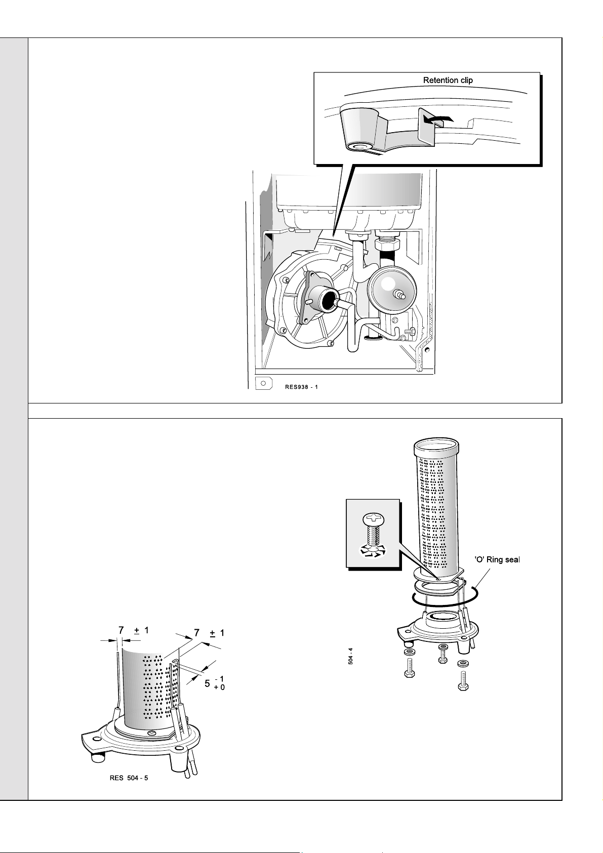
49
FAN REMOVAL AND CLEANING
1. Disconnect the pressure sensing pipe as
follows:
a. Undo the single top fixing screw on
the fan inlet venturi and slacken the
other 2 location screws.
b. Undo the 2 screws securing the
sensing pipe to the manifold block.
c. Slide the fan inlet venturi upward to
disengage and remove the venturi
and sensing pipe assembly.
2. Disengage the fan retention clip and rotate
the fan body to the right, to disengage the
bayonet fixing on the fan outlet.
3. Disconnect the electrical harness from the
fan.
4. Withdraw the fan with the 'O' ring seal.
5. Check that the fan impeller runs freely.
Clean with a soft brush or renew as
necessary. Refer to Frame 65 for
replacement.
Always take care when handling the fan,
Note.
in order to preserve the balance of the
impeller.
SERVICING
50
BURNER REMOVAL AND CLEANING
SERVICING
1. After removing the fan, as already described, disconnect
the 2 ignition leads and one detection lead from the
electrodes.
2. Undo the 3 fixing screws securing the burner assembly.
3. Withdraw the burner assembly downward and out of the
heat exchanger.
4. Brush off any deposits that may have collected on the
burner, ensuring that the flame ports are unobstructed.
Brushes with metallic bristles MUST NOT be used.
Note.
5. Inspect the spark and detection electrodes. Ensure they
are clean and in good condition - replace if necessary.
34
6. Check the spark and electrode gaps are correct.
7. Check that the spark and detection leads are in good
condition and renew as necessary
Response 80 / 100 / 120
- Installation
Page 35

SERVICING
51
CLEANING THE HEAT EXCHANGER
1. Place a plastic sheet or similar beneath the boiler
and remove all visible loose deposits from the
heat exchanger fins, using a suitable brush.
2. Take care to clean debris from the ledge inside
the combustion chamber.
52
RE-ASSEMBLY
Re-assemble the boiler in the following order:
1. Refit the burner, renewing any damaged or
deteriorating sealing gaskets.
2. Reconnect the 2 ignition leads and the detection lead.
5. Refit the fan venturi and sensing pipe assembly,
tightening all 3 screws on the venturi and the 2 screws
on the sensing pipe. (Ensure the 'O' ring seal is in place
before clamping the sensing pipe to the manifold
6. Refit the boiler sealing panel.
IMPORTANT. Ensure the boiler sealing panel is correctly
fitted and that a good seal is made.
3. Reconnect the fan electrical harness.
4. Ensure that the fan 'O' ring seal is in place then refit the
fan, engaging it in the bayonet fixing and locating it in
the retaining clip on the burner mounting plate.
53
BURNER PRESSURE CHECK
After any servicing, reference should be made to:
! Tables 2 and 3, page 3 (or the data plate), which quote
details of the burner pressures for the boiler models.
! Frame 45 'Gas rate.'
7. Refit the boiler front panel.
8. Turn on the gas supply at the gas service cock.
9. Reconnect the electrical supply.
Note that the pressure is set by the gas valve according to
fan speed, which in turn is controlled by reference to boiler
temperature and mode (CH/HW) thus the burner pressure
should be checked at maximum demand for CH or HW as
appropriate.
Frame 82 deals with possible causes of incorrect burner
pressure.
SERVICING
REPLACEMENT OF COMPONENTS
54
GENERAL
WHEN REPLACING ANY COMPONENT :
1. Isolate the electricity supply at the switched spur.
Note. T
2. Turn off the gas supply.
Note.
Finding section.
IMPORTANT. When work is complete the sealing panel must be correctly fitted, ensuring that a good seal is made.
THE BOILER MUST NOT BE OPERATED IF THE SEALING P ANEL IS NOT FITTED.
Response 80 / 100 / 120
urning the boiler on/off switch does not isolate the permanent live supply to the boiler.
In order to assist fault finding, the printed circuit boards are fitted with indicator lights . Full details are found in the Fault-
- Installation
35
Page 36

55
CH AND HW TEMPERATURE SENSOR REPLACEMENT
(Spares for both are identical)
1. Disconnect the electrical supply.
2. Remove the boiler front and sealing panels.
Refer to Frame 48.
3. Remove the fan (refer to Frame 49) : the CH and
HW thermistors are now exposed.
4. Close off the isolating cock(s) at the bottom of the
boiler, for CH or HW, as appropriate.
5. Release system pressure by opening the
appropriate drain cock(s).
pressure using the pressure relief valve - it may
cause debris within the system to foul the valve.
6. Disconnect the plug-in lead from the temperature
sensor and unscrew the sensor to release it.
7. Screw in the new sensor, using thread sealant,
reconnect and re-assemble in reverse order.
8. Open cock(s) and refill / repressurise pipework.
Do NOT release CH
SERVICING
9. Test fire the boiler.
10.Disconnect the filling loop (if used).
56
HW LIMIT THERMOSTAT REPLACEMENT
SERVICING
1. Disconnect the electrical supply.
2. Remove the boiler front panel. Refer to
Frame 48.
3. Remove the fan (refer to Frame 49) : the
HW limit thermostat can now be seen,
attached to the HW pipework by two
3.5mm screws.
4. Disconnect the leads from the
thermostat.
5. Release the 2 securing screws and
remove the old thermostat.
36
6. Fit the new thermostat, reconnect and re-
assemble in reverse order.
7. Reconnect the supply and test fire the
boiler.
Response 80 / 100 / 120
- Installation
Page 37

SERVICING
57
OVERHEAT THERMOSTAT REPLACEMENT
1. Disconnect the electrical supply to the boiler. Remove the electrical
connector (secured by one screw) from the boiler base.
2. Remove the controls panel. Swing the panel upside down and fix
with the long screws. Remove the bottom panel.
3. Release the screws securing the pressure
gauge subpanel and allow the panel to move to
one side.
4. Disconnect the leads from the overheat 'stat.
Undo the clamping nut to release the 'stat
head.
5. Undo the screw and clamp securing the
pancake sensing end of the thermostat to the
pipe
6. Replace with new thermostat. Re-assemble
and rewire in reverse order (electrical polarity is
immaterial).
58
SPARK AND DETECTION ELECTRODE REPLACEMENT
1. Remove front and sealing panels. Refer to Frame 48.
2. Remove the fan assembly. Refer to Frame 49.
3. Remove the burner assembly. Refer to Frame 50.
4. Undo the electrode securing bracket screws, as
required.
5. Fit new electrodes as necessary, ensuring that the
gaskets are in good condition and sealing correctly renew as necessary.
6. Check the spark / detection gaps. Refer to Frame 50.
7. Re-assemble in reverse order.
8. Check the ignition and operation of the burner.
The spark electrodes are replaced as a pair;
Note.
the detection electrode is a single probe.
59
SPARK GENERATOR REPLACEMENT
1. Remove the front and sealing panels. Refer to
Frame 48.
SERVICING
2. Remove the PCB cover.
3. Undo the securing screw and lift off the spark
generator cover (if fitted).
4. Disconnect the electrical leads from the spark
generator.
5. Withdraw the spark generator.
6. Fit the new spark generator and re-assemble
in reverse order.
7. Check the operation of the boiler.
Response 80 / 100 / 120
- Installation
37
Page 38

SERVICING
60
BURNER REPLACEMENT
1. Remove front and sealing panels. Refer to Frame 48.
2. Remove the fan assembly. Refer to Frame 49.
3. Disconnect the 2 ignition leads and one detection lead
from the electrodes.
4. Undo the 3 fixing screws securing the burner assembly.
5. Withdraw the burner assembly downward and out of the
heat exchanger, taking care not to damage the electrodes.
6. Remove the spark and detection electrodes. Refer to
Frame 58.
7. Remove the 3 securing screws and withdraw the burner
from the mounting flange.
8. Fit the new burner, replacing any damaged or
deteriorating gasket.
9. Re-assemble in reverse order.
Check the spark and detection gaps.
Note.
SERVICING
61
BURNER INJECTOR REPLACEMENT
1. Refer to Frame 48.
2. Unscrew the injector from the
gas injection pipe.
3. Check that the new injector is
of the correct size then screw
in place.
4. Re-assemble in reverse order.
38
Response 80 / 100 / 120
- Installation
Page 39
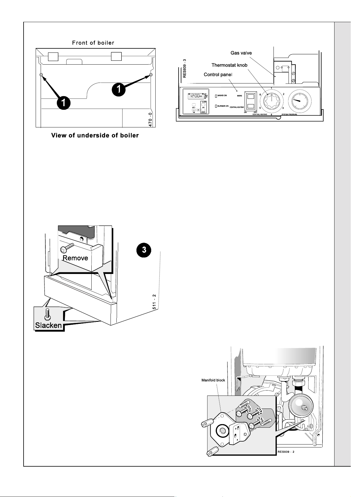
SERVICING
62
GAS CONTROL VALVE AND SOLENOID REPLACEMENT
T o replace the gas valve COMPLETE
Refer to Frame 54.
1. Remove the front and sealing panels. Refer to Frame
48.
T o replace ONLY the SOLENOIDS
a. Follow steps 3, 6 and 7.
2. Remove the casing bottom panel.
3. Remove the control panel. Disconnect the electrical
leads (noting their position for refitting) and place
panel safely to one side.
4. Remove the fan unit. Refer to Frame 49.
5. Remove the 2 securing screws from the pressure
gauge sub panel
6. Gently ease the pressure switch housing out of the
pressure switch sensing hose.
7. Unplug the electrical leads from the gas valve.
8. Undo the gas cock union connection.
9. Undo the 2 extended nuts retaining the gas injection
pipe and withdraw the pipe, taking care not to lose
the 'O' ring seal. Undo the third nut and the gas outlet
manifold block.
SERVICING
b. Undo the 2 retaining screws on the solenoids then pull
the solenoid to release.
c. Re-assemble in reverse order. Ensure step 13 (Frame
63) is followed.
Response 80 / 100 / 120
- Installation
39
Page 40

SERVICING
63
GAS CONTROL VALVE REPLACEMENT - continued
10.Supporting the valve, undo the 4
retaining screws and withdraw
the gas valve, leaving the plate
with the 3 studs in place.
11. Transfer the gas cock union and
elbow assembly to the new gas
valve, reusing the four M5 x 10
screws, together with the new 'O'
ring seal provided.
12.Fit the new gas valve in reverse
order, ensuring that the gas valve
gasket, manifold gasket and
injector pipe 'O' ring are all
undamaged
13.Operate the boiler for 10 minutes
at full DHW rate and check the
burner pressure / gas rate
against the value shown on the
data plate or in Table 3.
64
WATER PRESSURE GAUGE
1. Disconnect the electrical supply to the boiler.
SERVICING
2. Remove the bottom panel.
3. Remove the controls panel.
4. Close the isolating valves on the CH flow/return at the
base of the boiler then release CH system pressure by
opening one of the CH drain cocks on the isolating
valves.
It is not advisable to release system pressure using the
safety valve.
5. Unscrew the nut securing the
capillary at the CH flow pipe
boss and withdraw.
6. Squeeze the tabs to release the
pressure gauge.
7. Fit the replacement gauge and
reassemble in reverse order.
8. Close all drain cocks and open
both isolating valves.
9. Fit the filling loop. Fill the boiler
with water and pressure to 1 bar
(as appropriate). Reconnect
services.
10.After satisfactory test firing and
removal of air from the system
remove the filling loop.
40
Response 80 / 100 / 120
- Installation
Page 41

65
FAN UNIT REPLACEMENT
1. Remove the front and sealing panels. Refer to
Frame 48.
2. a. Undo the single fixing screw on the fan inlet
venturi and slacken the other 2 location
screws.
b. Undo the 2 screws securing the sensing pipe
to the manifold block.
c. Slide the fan inlet venturi upward to
disengage and remove the venturi and
sensing pipe assembly.
3. Disengage the fan retention clip and rotate the fan
body to the right to disengage the bayonet
fixing on the fan outlet.
4. Disconnect the electrical leads from the fan.
5. Withdraw the fan.
Note.
Always take care when handling the fan in
order to preserve the balance of the impeller.
6. Fit the new fan, ensuring that:
a. All seals are correctly refitted.
b. The sensing pipe is correctly refitted.
c. The fan is fully engaged.
SERVICING
7. Check the operation of the new fan.
65A
FLOW RESTRICTOR CLEANING / REPLACEMENT (where fitted)
The restrictor is a plastic piece fitted between the
lower and upper cold pipe assemblies.
To access the flow restrictor proceed as follows:
1. Close the cold water inlet valve below the boiler.
2. Open a hot water tap to relieve the pressure in the
expansion vessel and pipework.
SERVICING
Response 80 / 100 / 120
- Installation
3. Drain using the valve nipple.
4. Undo the bulk head fitting shown.
5. Slacken the nut on the other end of the lower cold pipe
assembly.
6. Clean or renew as necessary. Re-assemble in reverse
order.
41
Page 42
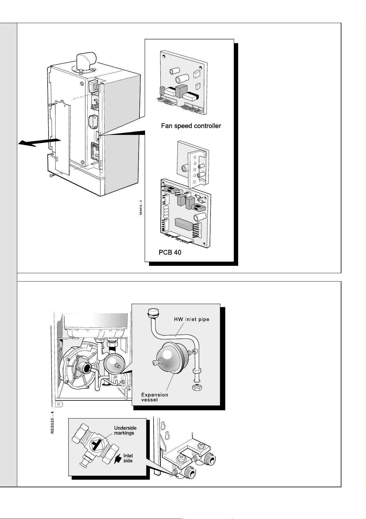
66
PRINTED CIRCUIT BOARD REPLACEMENT
SERVICING
SERVICING
PCB 41
The Response uses:
PCB 41 - Ignition sequence
PCB 40 - Logic sequence
Fan speed control
1. Isolate the electrical supply.
Refer to Frame 54.
2. Remove the front panel.
3. Remove the PCB cover
4. Disconnect all 'Molex' plugs
feeding the PCB to be
changed.
5. Release the clips and
remove the PCB.
6. Fit the new board onto the
clips.
7. Replace all 'Molex'
connectors. Note that the
connectors are made noninterchangeable. If in doubt,
refer to Frame 40 - Pictorial
Wiring.
8. Reassemble in reverse
order
9. Test both DHW and CH
modes of operation.
67
HW EXPANSION VESSEL
1. Disconnect the electrical
supply to the boiler.
2. Remove the front and sealing
panels. Refer to Frame 48.
3. Close the isolating valve on
the HW supply then release
pressure by opening a hot tap.
Note.
Ensure valve markings
are as shown.
4. Drain, using the drain point on
the isolating valve.
5. Unscrew the HW expansion
vessel, which may be fingertight. If necessary, remove the
fan (see Frame 65). To access
use a spanner on the hexagon
nut behind the vessel.
6. Replace with new sealing
gasket and vessel.
Reassemble in reverse order
and test fire.
42
Response 80 / 100 / 120
- Installation
Page 43

SERVICING
68
PUMP REPLACEMENT
Note.
The Grundfos 15/60 pump is available in several
versions, according to the position of the electrical connector
in relation to the pipework. Check that you have the correct
version - see step 9.
1. Isolate the electrical supply. Refer to Frame 54.
2. Remove the boiler bottom panel.
3. Remove the controls panel.
If a programmer is fitted it is necessary to disconnect the
programmer harness at the terminal block.
4. Close the valves on the CH flow and return pipework
below the boiler.
5. Drain down (refer to Frame 68) by opening the CH drain
cock. Do not release system pressure using the
pressure relief valve as it may cause debris within the
system to foul the valve.
6. Loosen the pump outlet union and the inlet connection at
the rear of the CH return isolating valve.
7. Unplug the inline electrical connector.
8. Disconnect the pipework fully and remove the old
pump, together with the short inlet pipe.
9. Ensure that the replacement pump has the motor
positioned so that the
on the same side as the inlet pipe.
use an Allen key to remove the motor and
reposition it.
10.Transfer the short inlet pipe to the
replacement pump, using a new sealing washer.
11. Make the electrical connections.
12.Offer the pump / pipe assembly to the boiler,
using the second new washer on the pump outlet
union. Tighten the water connections.
13.Close the drain cock and open the system
isolating valves. Fit the filling loop - fill, vent and
pressurise to 1 bar (or as required).
14.Restore services and operate the heating controls
to test-fire the boiler.
15.Vent air and top up the pressure again, if required.
16.Remove the filling loop.
electrical connections are
If necessary,
inlet
side of the
69
HEAT EXCHANGER REPLACEMENT
WARNING.
services, including the flue turret.
Refer also to Frame 7 - 'Boiler Exploded View'.
Note.
the pre-piping frame the replacement will be more easily
conducted if this is done. If this is possible remove the boiler
after step 6.
1. Isolate the electrical and gas supply to the boiler.
2. Isolate the water and gas supplies by closing 3 cocks
below the boiler.
This will necessitate disconnection of all
If the installation allows the boiler to be removed from
SERVICING
Note.
Do not close the DHW restrictor ball valve.
3. Remove the boiler front panel and inner sealing panel.
Refer to Frame 48.
Response 80 / 100 / 120
- Installation
43
Page 44

SERVICING
70
HEAT EXCHANGER REPLACEMENT - continued
4. Remove the bottom panel.
5. Attach drain pipes to the 2 boiler drain points. Open the
CH drain by turning the grey knobs and the HW drain by
slackening the drain point. Note the marking on the bottom
of the valves. Refer to Frame 68.
6. While the boiler is draining, release the turret clamp on top
of the boiler, together with the screw securing the turret to
the flue pipe. Remove the turret.
7. Remove the fan, venturi and sensing pipe. Refer to
Frame 49.
8. Unscrew and remove the HW expansion vessel.
9. Undo the 2 extended nuts securing the gas injection pipe
and remove.
10.Disconnect the spark electrode leads and the flame
sensing electrode lead at the burner base. Refer to Frame
58.
11. Remove the 3 screws securing the burner assembly and
withdraw the assembly downward, taking care not to
damage the electrodes. Refer to Frame 60.
12.Unplug the electrical leads from both CH and HW
temperature sensors and HW overheat thermostat.
13. Unscrew the nut securing the bottom of the HW inlet pipe
together with the hexagon socket screw retaining the
upper end. Rotate the pipe to clear the bulkhead connector
and then pull down to remove.
14. Unscrew the nut on the CH flow and return pipes to the
heat exchanger.
15.Unscrew the nut securing the bottom of the HW outlet pipe
together with the hexagon socket screw retaining the
upper end.
SERVICING
16.Unscrew the locknut on the bulkhead fitting for the HW
outlet pipe.
17.Unscrew the compression nut securing the HW outlet pipe
to the pre-piping frame.
18.Pull down the HW outlet pipe to remove.
19.Unscrew and remove the automatic air vent from the top of
the heat exchanger.
21. Remove the 2 nuts securing the left support bracket to the
chamber side and remove the left support bracket.
22. Supporting the weight of the heat exchanger, slacken the
screw on the right support bracket and allow the bracket
to its lowest position.
23.Lift out the heat exchanger.
24.Re-assemble in reverse order, using new gaskets as
appropriate.
25.Before refitting the fan, ensure the wires have been
reconnected to the:
- CH thermistor (
- HW thermistor (
- Flame detection electrode (
26.When re-assembly is complete, fit the filling loop, close
all drain points, open all isolating valves and ensure that
the boiler is filled, vented of air and pressurised before
attempting to fire it.
27.After a satisfactory test firing, remove the filling loop (this
is a requirement of the water bylaws).
violet pair
grey
)
)
yellow
)
20.Remove the 2 screws securing the heat exchanger to the
support brackets, together with the top clamping screw.
44
Response 80 / 100 / 120
- Installation
Page 45
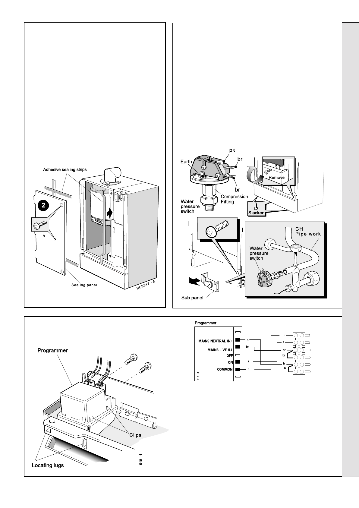
71
BOILER SEALING PANEL SEAL
1. Refer to Frame 48.
2. Remove the screws and disengage panel.
3. Remove the old seals and thoroughly clean the
casing surfaces.
4. Fit the new self adhesive seals, 3 to the panel
and 1 the casing .
5. Re-assemble in reverse order.
Note.
Ensure that the boiler sealing panel is correctly
seated, compressing the sealing strip to make an
airtight joint.
SERVICING
72
WATER PRESSURE SWITCH
1. Disconnect the electricity supply. Refer to Frame 54.
2. Close the CH flow and return isolating valves at the bottom of
the boiler. Use the drain points on these valves to release
system pressure and drain down. (It is not advisable to
release system pressure using the safety valve manual knob
as this can cause debris to lodge in the valve).
3. Remove the controls panel. If programmer is fitted, it is
necessary to disconnect the programmer harness at the
terminal block.
4. Remove the pressure gauge sub panel.
5. Remove the wires from the switch.
6. Unscrew the compression fitting and remove the pressure
switch.
7. Reassemble in reverse order.
73
PROGRAMMER REPLACEMENT (if fitted)
1. Refer to Frame 54.
SERVICING
2. Remove the casing front panel. Refer to Frame 48.
3. Disconnect the programmer terminal block.
4. Remove the control panel. Refer to Frame 65.
5. Undo the 2 retaining screws and withdraw the programmer,
complete with mounting bracket, from the control panel.
Response 80 / 100 / 120
- Installation
6. Compress the clips on the sides of the programmer and
withdraw it from the retaining bracket.
7. Fit the new programmer and re-assemble in reverse order.
8. Check the operation of the new programmer.
45
Page 46
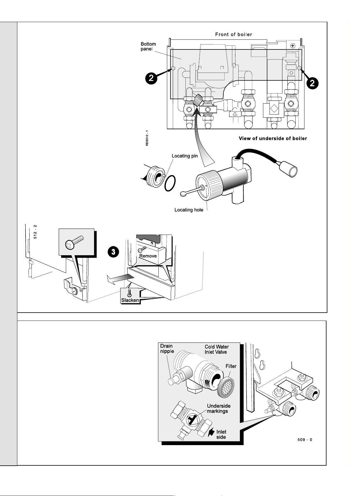
74
WATER FLOW SWITCH REPLACEMENT
1. Isolate the electrical supply. Refer to
Frame 54.
2. Remove the boiler bottom panel .
3. Remove the controls panel. If a
programmer is fitted it is necessary to
disconnect the programmer harness at
the terminal block.
4. Close the cock on the HW inlet pipe
below the boiler.
5. Drain down. Refer to Frame 68.
6. Disconnect the flow switch electrical
lead at the in line connector.
7. Undo the knurled fixing nut and withdraw
the flow switch.
8. Fit the new flow switch, ensuring that the
locating pin and hole are correctly
positioned.
SERVICING
SERVICING
75
INLET FILTER CLEANING
The filter comprises a gauze disc in a synthetic
rubber carrier ring. It is secured at the front (outlet) of
the cold water isolating valve by means of the union
connection between the valve and the boiler inlet
pipework. to access the filter, proceed as follows:
1. Close the cold water inlet valve below the boiler.
Ensure the markings are as shown.
2. Open a hot tap to relieve the pressure in the
expansion vessel and pipework.
9. Complete the reassembly in
reverse order.
10.Open the isolating valve and
bleed air out at the tap(s).
11. Reconnect the electrical supply
and open a HW tap to test
operation of the boiler.
3. Drain, using a valve nipple.
4. Undo the union connection referred to above, and
remove the filter disc.
5. Clean or renew the filter disc. Reassemble in
reverse order.
46
Response 80 / 100 / 120
- Installation
Page 47
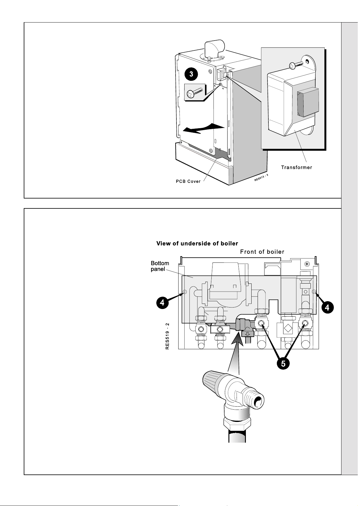
76
MAINS TRANSFORMER REPLACEMENT
1. Isolate the electrical supply to the boiler.
Refer to Frame 54.
2. Remove the boiler front panel. Refer to
Frame 48.
3. Release the screws securing the PCB
cover and remove the cover.
4. Disconnect the transformer electrical
leads at the in-line connector
5. Release the transformer mounting
screws.
6. Fit the replacement transformer and
complete the reassembly in reverse
order.
SERVICING
77
PRESSURE RELIEF VALVE (Safety Valve) REPLACEMENT
1. Isolate the electrical supply. Refer to
Frame 54.
2. Remove the pump. Refer to Frame 69.
3. Disconnect the mains electrical
connection from the bottom panel.
Disengage the 2 halves of the
connector.
4. Remove the boiler bottom panel.
5. Close the cocks on the CH flow and
return pipework below the boiler. Drain
down. Refer to Frame 68.
6. Disconnect the discharge pipe to the
pressure relief valve.
7. Undo the connection securing the valve
to the boiler.
8. Replace with a new valve and restore
the pipework, in reverse order, using
new sealing washer.
SERVICING
9. Open cocks, fit filling loop, fill, vent and
pressurise to 1 bar (or as required).
10.Restore the electrical supply and set the
heating controls, to test-fire the boiler.
11. Vent air and top up the pressure again,
as required.
12.Remove the filling loop.
Response 80 / 100 / 120
- Installation
47
Page 48

78
CH EXPANSION VESSEL REPLACEMENT
If the CH expansion vessel is faulty, there are 3 options:
SERVICING
A. If it has a punctured diaphragm, but is
and a new vessel added to the system, external to the boiler, provided it is of adequate
capacity and pre-charge pressure.
B. If there is at least 600mm clearance above the boiler, the expansion vessel can be
changed without removing the boiler (RH exit flues will have to be disturbed). Access to
the water connection of the expansion vessel is
boiler panel (if there is 200mm RHS clearance) or by removal of the fan and gas valve.
C. If there is insufficient headroom, the boiler will need to be removed. In this case,
access to the water connection of the expansion vessel will be possible by removing
the RH boiler side panel.
View of underside of boiler
Front of boiler
res 6101
otherwise leak free,
either
then it can be left in place
by removal of the right hand side
For option B, proceed as follows:
B1.Isolate the electric, gas, and water services.
B2.Drain down the boiler CH circuits, using the appropriate
drain cocks.
B3.Where RH clearance is available. Unscrew the 10 screws
securing the RHS panel and remove the panel to gain
access to the expansion vessel connector.
Where RH clearance is NOT available. Remove the fan
(refer Frame 49) and gas valve (refer Frame 62) to gain
access to the expansion vessel connector.
B4.Disconnect the flue, if RH exit, and remove to the right
(general details are reverse of Frames 18 & 28).
SERVICING
C3.Undo all service unions at the base of the boiler, and
unplug and disconnect the electrical supply lead, which is
secured by one screw in the centre of the boiler base.
C4.Disconnect the flue turret and place to one side (reverse of
the assembly described in Frames 18 & 28).
C5.Lift the boiler off the wall and place horizontally, at a
convenient working height.
C6.Follow instructions B3 to B6.
C7.Return the boiler to the wall mounting frame, remaking all
connections, including the flue.
C8.Fill, pressurise and test.
C9.Remove the filling loop.
B6.Undo the water connection at the bottom of the expansion vessel.
B7.Fill, pressurise and test.
B8.Remove the filling loop.
For option C, proceed as follows:
C1.Isolate the electrical, gas and water services.
C2.Drain down the boiler CH/HW circuits using the appropriate boiler
B5.Undo the 3 screws securing the boiler panel above the
expansion vessel, and remove the panel.
Lift out the vessel and fit the replacement, reassembling in reverse
order - using new gaskets and 'O' rings where appropriate.
drain cocks (refer Frame 68).
48
Response 80 / 100 / 120
- Installation
Page 49
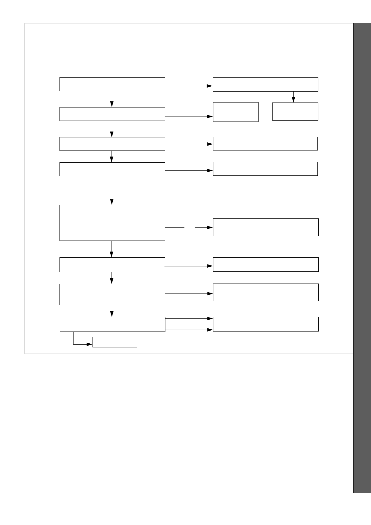
79
FAULT FINDING MAIN MENU
ST ART THE BOILER FROM COLD
FAUL T FINDING
WARNING.
first isolating the mains supply .
Note.
Switching the boiler on/off switch 'off' when a frost thermostat is wired
directly from the mains may leave a live feed to the boiler.
No part of the boiler should be touched without
Does the boiler provide HW ?
NO
Does the boiler provide CH ?
NO
Is the water system pressure low ?
NO
Does the fan run correctly ?
YES
Can the correct burner pressure be
measured during an ignition
attempt (i.e. when PCB 41 LED2
goes OFF briefly)?
Correct pressure
Has the gas line been purged of air ? Purge gas line
YES
YES
YES
NO
No pressure
or
wrong pressure
NO
Does the boiler provide CH ?
Go to Frame 81 Go to Frame 80
Go to Frame 86
Go to Frame 82
Go to Frame 83
NO
YES
Is there a spark at the ignition
electrodes during an ignition attempt ?
YES
Does the boiler light ?
YES
The correct sequence of operation during ignition is as
follows:-
1. Mains to boiler with water pressure switch and overheat
thermostat closed.
2. a. Hot water tap turned on (HW and Fan lights come on)
- the flow switch signals this to PCB 40, which starts
the fan at full speed and sends power to Ignition
Control PCB 41.
or b. Clock, heating switch and room thermostat call for
heat (CH and Fan lights come on) - PCB 40 senses
this, starts the fan at full speed and sends power to
the pump and Ignition Control PCB 41.
EXIT
YES but only
NO
NO
briefly
3. If the fuse on PCB 41 is OK, the 'power' and 'lockout' LEDs
PCB 41 illuminate.
4. After 8 seconds pre-purge time 'lockout' LED 2 goes OFF,
the spark starts and the gas valve opens.
5. If a flame is detected the spark stops, 'lockout' LED stays
OFF and the 'Burner on' neon lights - the fan speed and
gas rate then adjust as dictated by boiler water
temperature.
6. If a flame is not detected the spark stops, the gas valve
closes, the fan continues to run for a post purge. The gas
valve reopens and the spark restarts. PCB 41 will attempt 4
ignitions. If all 4 attempts fail the 'lockout' LED comes ON.
Go to Frame 84
Go to Frame 85
or c. Both the above call for heat (HW and Fan lights
come on) - HW takes priority, i.e. pump OFF, fan
running at full speed, power to PCB 41.
Response 80 / 100 / 120
- Installation
Foot Note:
checked with a multimeter set to the appropriate AC range
(apply the other probe of the meter to mains neutral, e.g. on
terminal N of the programmer terminal strip).
Presence of Live supply on a terminal may be
FAULT FINDING
49
Page 50

FAUL T FINDING
80
HW but no CH
WARNING.
. At the end of a call for heat by the room thermostat / time control, a 2 minute pump overrun period occurs. During this
Note 1
When panels are removed for service, live parts are exposed so caution should be exercised when fault-finding.
time the boiler will not restart for CH even if the controls are calling for heat. This is done to prevent uneconomical
'short cycling.' This period can be curtailed by running a hot tap for a few seconds.
Is the CH light on PCB 40
NO
Is the pump
running ?
NO
Is there power to
the pump at the
connector on
PCB 40 ?
NO
YES
YES
flashing
closed valves
?
Is the boiler
hot ?
YES
Check for air
locks and
preventing
proper
circulation
Is there power at the
pump itself ?
NO
YES
YES
NO
Check the CH sensor and panel
control and/or the wires connecting
them to the PCB.
Are the wires and connections OK ?
YES
Unplug the lead from the CH sensor
and connect temporarily to a
replacement sensor, if available.
(Alternatively, see footnote.)
Does the boiler now operate ?
YES
Fit new CH
sensor
Check all connections to PCB 40.
Check for moisture on PCB 40.
If no fault found check PCB 40 by
substitution.
NO
If you are
lead to the flow switch at PCB
Does the boiler now give CH
FAULT FINDING
Is the HW light lit
on PCB 40 ?
YES
Check that there is no flow,
e.g. to taps or automatic
washing machines.
being used, disconnect the
NO
Check that
heating
controls are
all calling for
heat and are
correctly
wired.
sure
there is no HW
40.
?
If no fault
found
Check
the lead
to the
pump
If no fault found check PCB 40 by substitution.
NO
YES
If the boiler has been unused with
mains off, the pump may be stuck.
Remove screw cap on the pump
head and turn the shaft with a
screwdriver until free.
Does the pump now run ?
Check all connections to PCB 40.
Check for moisture on PCB 40.
Reconnect the
flow switch
Change faulty
flow switch
CHECKING CH AND HW THERMISTOR SENSORS
The sensors can be checked by measuring their
resistance, using a suitable multimeter connected
across the sensors' terminal pins.
At room temperature expect
9,000 to 11,000 Ohms
At 60°C. expect 2,000 to 2,500 Ohms
At 85°C. expect 1,000 to 1,500 Ohms
YES
NO
Replace
cap
Switch off
and change
pump
50
Response 80 / 100 / 120
- Installation
Page 51

FAUL T FINDING
81
CH but no HW
WARNING.
When panels are removed for service, live parts are exposed so caution should be exercised when fault-finding.
Is the HW light on PCB 40
Is there a flow of at least 3.5 litres per
minute (or about 1 pint in 10 seconds)
when a hot tap is turned on ?
YES NO
Switch off the boiler.
Unplug the flow switch lead
at the inline connector.
Measure continuity between
the switch leads and turn a
hot tap on.
Does the switch close ?
flashing
NO
?
YES
Adjust the restrictor ball valve
to give the required flow.
If this is not possible rectify a
system pipework defect or a
supply pressure problem.
Check the flow restrictor for
blockage.
Unplug the lead from the sensor
and connect it temporarily to a
replacement sensor, if available.
(Alternatively, see footnote)
Does the flashing stop ?
YES
Fit new HW
sensor
Check - and
repair or
replace the
sensor
Does boiler
operate ?
Check all connections
to PCB 40.
Check for moisture on
PCB 40.
If no fault found check
PCB 40 by substitution.
NO
lead.
NO
YES
Reconnect the flow
switch.
Unplug the lead from the
HW sensor and transfer
temporarily to a
replacement sensor.
Will the boiler operate ?
NO
Check all connections to
PCB 40.
Check for moisture on
PCB 40.
If no fault found check
PCB 40 by substitution.
YES
NO
Change the flow switch
Fit new HW sensor (which has
failed 'low resistance')
Checking CH and HW thermistor sensors
The sensors can be checked by measuring their resistance,
using a suitable multimeter connected across the sensors'
terminal pins.
At room temperature expect 9,000 to 11,000 Ohms
At 60°C. expect 2,000 to 2,500 Ohms
At 85°C. expect 1,000 to 1,500 Ohms
Response 80 / 100 / 120
- Installation
FAULT FINDING
51
Page 52
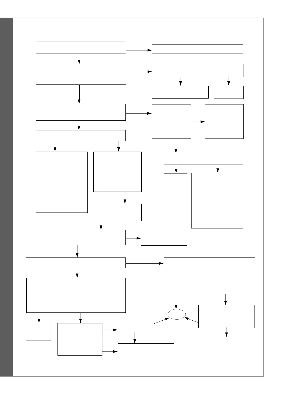
82
Fan not running
FAUL T FINDING
WARNING.
When panels are removed for service, live parts are exposed so caution should be exercised when fault-finding.
Is the system pressure gauge indicating
water pressure below 0.5 bar ?
NO
Make sure the boiler mains switch is ON
and the heating switch is on, if required.
Is the 'Mains On' neon lit ?
YES
Is there a supply at PCB 40 at its mains input
connector? (Expect 230V 50 Hz ± 10%)
YES
Has the
Check pump for shorts
between L/N and L/E.
disconnect the pump
reconnect each item
mains
fuse F2 on PCB 40 blown ?
YES
If no fault found
and lead to PCB 41,
renew fuse and
one by one until the
faulty item is
determined
NO
Is there mains voltage
between primary
terminals (brown and
blue leads) of mains
transformer ? (Expect
230V 50Hz ± 10%)
YES
Check lead to
transformer
NO
YES
NO
NO
Go to Frame 86
Is there mains voltage to the boiler ?
YES
Check connections and
continuity of EMC filter
Has overheat
'stat tripped ?
(reset button
under RHS of
boiler)
YES
Can it be reset when the boiler is cold
NO
Replace
overheat
'stat
NO
Reset 'stat. Check
temperatures as the
boiler warms up. If the
overheat 'stat trips:
below 90° - replace the
above 90° - check CH/
HW thermistors and
replace as required.
external fault
Check continuity
of the water
pressure switch
and overheat
'stat - replace as
required.
?
overheat stat.
NO
Rectify
YES
Is there 24-28 V AC between secondary
terminals (red and black leads) of transformer
?
YES
Has secondary fuse F1 on PCB 40 blown ?
YES
Replace fuse. Examine fan harness, checking
especially for short circuits between wires or
terminals.
If no fault found, power up board
harness connected.
YES
Replace
PCB 40
Foot Note:
of the meter to mains neutral, e.g. on terminal N of the programmer terminal strip).
FAULT FINDING
Presence of live supply on a terminal may be checked with a multimeter set to the appropriate AC range (apply the other probe
harness and fan and
Does the fuse blow ?
Does fuse F1 blow ?
Reconnect the
restore power.
without fan
NO
NO
YES
NO
Does the fan
run ?
Check fan by substitution
Replace transformer
NO
YES
NO
Examine fan wiring harness, checking
especially for loose connections or
disconnected wires.
If no fault found, check fan by substitution.
Does replacement fan run OK ?
NO
NO
EXIT
YES
Refit original fan. Check
YES
PCB 40 by substitution.
Does fan now run ?
Leave replacement PCB fitted
but check the fuses on it.
Fit replacement fan.
52
Response 80 / 100 / 120
- Installation
Page 53

FAUL T FINDING
Power to PCB 41 but burner pressure incorrect or zero
83
Notes.
1. The burner pressure is not user-adjustable: it is regulated by the gas valve, according to the air flow generated by the fan and, on cold
ignition, should be slightly higher than the value quoted on the Data Plate. Long flues will cause a slightly lower burner pressure than
standard flues.
2.
Equilibrium fan differential pressures should be as detailed in Frame 45.
Is the fuse good on PCB 41?
(LED3 lit confirms this)
YES
Is the appliance gas cock fully open ?
YES
Is the gas supply pressure adequate at
the appliance inlet during an ignition
trial period (i.e. when LED 2 on PCB 41
goes off) ?
YES
Are air and flue ducts free from blockage ?
YES
NO
NO
NO
Check all items connected to PCB 41
for short circuits between Live and
Neutral, also between Live and Earth.
If none found, reconnect one by one
(gas valve last) until the faulty item is
found.
If no fault found or fuse blows with no
items connected, check PCB 41 by
substitution.
Is the supply pressure correct at the
gas meter ?
YES
Determine the cause of
pressure loss (e.g. supply
pipe too small ?) and rectify
Clear the blockage and take steps to
prevent recurrence
NO
Contact the
gas
supplier
Is the fan pressure sensing pipe correctly
connected, free from damage and
unobstructed by solid matter or moisture
?
YES
Is there Live on the brown lead of the gas
valve connector on PCB 41
ignition trial period
Are both connectors correctly fitted to the
gas valve, with screws secured
overtightened ?
Remove connectors. With mains OFF,
check continuity of leads from each socket
unit back to the corresponding terminals in
the control box. Are leads in good order ?
during an
?
YES
but not
YES
NO
YES
NO
NO
Change lead assembly
Replace gas valve solenoids
Rectify the fault and take steps to
prevent recurrence
Check PCB 41 by substitution
Replace gas valve
NO
Is burner pressure
correct ?
YES
Return to main
menu
Response 80 / 100 / 120
- Installation
FAULT FINDING
53
Page 54

Spark generation and ignition
84
FAUL T FINDING
WARNING.
Note.
When panels are removed for service, live parts are exposed so caution should be exercised when fault-finding.
Do not attempt to measure the voltage between the spark generator output (spark) leads !
Fan and gas supply OK. Correct burner
pressure can be confirmed during ignition
attempts. Ignition spark suspect
Is there mains voltage on PCB 41 terminals
for the spark generator
period (i.e. when LED 2 goes OFF briefly) ?
Is there mains voltage at the spark
generator during ignition ?
Are the mains leads at the spark
generator correctly fitted to the tags ?
during ignition trial
YES
YES
NO
NO
NO
Check connections on PCB 41.
If no fault found, check PCB 41 by
Check leads to the spark generator
substitution
Rectify faulty connection
YES
Is there evidence of the spark 'tracking'
(jumping across electrodes or leads)
externally to the burner ?
YES
Rectify poor connections or replace the
spark generator or electrodes
Remove the fan and burner assembly and
reconnect spark leads to the electrode
terminals.
Check that the gap between terminals is 4
to 5mm and that the distance to the flame
strip is 7mm (± 1mm).
With gas OFF, do another ignition cycle.
Is the spark OK now ?
YESNO
NO
YES
Disconnect HT leads from the spark
electrodes.
Place the leads so that the connectors
are 3 to 5mm apart and clear of other
metalwork.
WARNING
Do NOT hold the leads
Turn off the boiler gas cock.
Is there a spark between the HT leads
during ignition ?
NO
Replace faulty spark generator and
restore gas supply
FAULT FINDING
54
Fit a new
ignition
electrode
assembly
Re-assemble and
restore gas supply.
Boiler should now
light and the
'Burner On' neon
illuminate
Return to main
menu
Response 80 / 100 / 120
- Installation
Page 55

Flame detection and mixture
85
FAUL T FINDING
WARNING.
between the electrode and earth with the lead
When panels are removed for service, live parts are exposed so caution should be exercised when fault-finding.
Boiler does not light, or lights briefly
at the
correct
burner pressure then
goes off, leaving LED 2 on PCB 41 lit
Is this a new installation ?
NO
Has any electrical work been done to the
boiler or the house wiring ?
NO
Remove the fan.
Is the detection lead undamaged and
attached to the (single) detection electrode
terminal at the rear of the burner base ?
YES
Remove the burner assembly.
Check the detection electrode visually for
damage / contamination / moisture.
If possible, check insulation resistance
disconnected - this should be at least 100
Megohms.
Is it OK ?
YES
YES
Check that the gas injector is unobstructed.
YES
Check the polarity of the incoming mains to
the boiler (see footnote).
Is this correct ?
YES
Check the polarity of the mains input to
PCB 41 when the fan starts.
Is this correct ?
YES
NO
Does the boiler now run ?
YES
Check detection lead for continuity.
Check that the electrode is in the flame area
and within 7mm (± 1mm) of the burner at
closest point.
Rectify any fault.
Does the boiler now run ?
NO
Check all connections on PCB 41.
Check for moisture on PCB 41.
If no fault found, check PCB 41 by substitution.
Foot Note: POLARITY CHECKS
Use a multimeter (set to measure 230 V AC or more), connecting the black lead to a reliable
particular test)
You should find 230 V on terminal L and zero (or a small reading) on terminal N.
Some meters may trip residual current devices during this test.
N.B.
Response 80 / 100 / 120
.
- Installation
YES
EXIT
YES
Earth
point (
not Neutral for this
FAULT FINDING
55
Page 56

FAUL T FINDING
Low system pressure indicated on pressure gauge.
86
Check the pressure on the gauge on the boiler
control panel.
Is it reading below 0.5 bar ?
YES
Is this a new
installation ?
NO
YES
Fill and
pressurise the
system
NO
Check that the wiring to the low water
pressure switch terminals 1, 2 and 3
corresponds with that shown in the wiring
diagrams.
Was an error found ?
NO
Increase the system pressure, if necessary,
to 1 bar.
Does the boiler now operate ?
NO
Has it
recently
been
extended ?
NO
Has it been partly
drained to move a
radiator ?
NO
Are there any obvious leaks ?
Fill and repressurise the system but leave
Check boiler heat exchanger, all CH
pipework and radiators for leaks, including
loft or underfloor pipes where used.
Fire the boiler up on CH.
Observe pressure gauge
as system reaches
temperature.
Does pressure reach (or
exceed) 2.5 bars ?
YES
the boiler OFF.
Was a leak found ?
NO
Is volume of the system
consistent with volume of
the expansion vessel(s)
fitted ?
YES
Fill and
repressurise the
system
Check for
YES
obstruction
in the pipe
feeding the
expansion
YES
NO
vessel
Is there continuity between terminals 1
and 3 on the low water pressure switch ?
NO
Add extra
expansion
volume
Use a drain cock (
pressure on the boiler pressure gauge. Remove cap
from the air valve on the expansion vessel.
Measure air pressure with a car tyre pressure gauge.
Is it at least 0.8 bar (12 lb/in
YES
Unscrew the Schrader valve from expansion
vessel and fit new valve (e.g. from car tyre sales
Repressurise expansion vessel to 1 bar (15 lb/in
Does vessel pressure hold up ?
repressurise
not the safety valve
outlet).
YES
Fill and
system
NO
Change
pressure
switch
) to release all
2
) ?
NO
NO
Replace
expansion
vessel
2
).
Check discharge pipe from the
Has it been discharging water ?
FAULT FINDING
56
NO
safety valve (this may well be
outside the building).
NO
Recheck for leaks on
pipes and radiators
YES
Is the safety valve free
from foreign matter,
correctly set and in the
closed position ?
NO
Clear and re-adjust the valve.
Repressurise the system
YES
Replace safety valve and
refill / repressurise
Response 80 / 100 / 120
- Installation
Page 57

SHORT LIST OF P ARTS
87
BURNER ASSEMBLY - Exploded View
LEGEND
1. Burner.
2. Burner injector.
3. Gas valve.
4. Flame sensing electrode.
5. Ignition electrode.
19. Fan assembly.
Response 80 / 100 / 120
- Installation
28. Pressure sensing pipe.
29. Sensing pipe clamp plate
54. Fan / burner mounting 'O' ring.
55. Fan 'O' ring.
56. Pressure pipe 'O' ring.
57. Gas manifold gasket.
58. Gas valve gasket.
68. Gas cock
74. Injector pipe 'O' ring.
75. Gas elbow 'O' ring.
1/2".
57
Page 58

CONTROLS AREA - Exploded View
88
SHORT LIST OF P ARTS
Legend
7. PCB 41.
8. PCB 40.
58
9. Fan speed control board
10. Spark generator assembly.
30. EMC filter.
67. Transformer assembly.
Response 80 / 100 / 120
- Installation
Page 59

SHORT LIST OF PARTS
The following are parts commonly required as replacements, due to
damage or expendability. Their failure or absence is likely to affect the
safety and/or performance of this appliance.
The list is extracted from the British Gas List of Parts which contains all
available spare parts.
The full list is held by British Gas, Caradon Plumbing Limited distributors
and merchants.
Key No. G.C. Part No. Description Qty. Product No.
1 Main burner , c/w: 1 off burner gasket, 3 off M4 shakeproof washers,
3 off M4 x 6 lg. pozi pan hd. screws, 1 off 'O' ring, 1 off fan and burner mount
E26-304 Response 80 1 075524
E26-312 Response 100/120 1 075529
2 Main burner injector
E00-042 Bray cat 10 /2300 C Response 80 1 139745
E01-796 Bray cat 10 /3800 C Response 100/120 1 151010
3 Gas valve (SIT ref. 0.828.113) (calibrated) fitted with 1 off M5 x 20 lg. stud,
c/w: 1 off gas valve gasket,
4 off M4 x 12 lg. pozi pan hd. screws,
4 off M5 x 10 lg. pozi pan hd. screws, 1 off O' ring
E01-143 Response 80 1 075212
E01-797 Response 100/120 1 075213
When ordering spares please quote:
1. Boiler model (see Data Plate)
2. Appliance G.C. number (see Data Plate)
3. Description.
4. Quantity.
5. Product No.
4 Flame sensing electrode (Buccleuch), c/w:
1 off sensing electrode gasket, 1 off M4 x 10 lg pozi pan hd. screw,
1 off M4 shakeproof washer 1 152033
5 E01-972 Ignition electrode (Buccleuch), c/w:
1 off ignition electrode gasket, 1 off M4 x 10 lg. pozi pan hd. screw,
1 off M4 shakeproof washer 1 075269
7 E00-046 PCB 41 (Pactrol), c/w: 4 off PCB stand-offs 1 172853
8 E01-800 PCB 40 (Pactrol), c/w: 4 off PCB stand-offs 1 075264
9 E01-801 Fan speed control board (EBM) c/w 4 off PCB stand-offs 1 075265
10 E02-140 Spark generator assembly 1 151355
11 E00-049 Thermostat, boiler overheat (Ranco ref. LM7 T95 - 336) 1 138719
12 Water pressure switch assembly (Novomec ref.650 2211 037), c/w: adaptor 1 173227
13 E02-044 Thermostat, DHW overheat (Elmwood ref. 2455R), c/w:
2 off M3.5 x 6 lg. Taptite screws 1 075266
14 E00-052 CH and DHW sensor, c/w: 1 off fibre washer 10 I.D. 1 075201
15 E01-952 Potentiometer harness - includes potentiometer 1 151354
16 E00-054 Potentiometer knob. 1 139296
17 E00-055 Pressure gauge (Imit ref. lc - 964 / 66228) 1 138953
18 E00-056 Rocker switch (Arco Electric No. H8600 VB - white)
(1 off mains on/off, 1 off CH on/off switch) 1 139603
19 E01-953 Fan assembly 1 139368
21 E00-059 Pressure relief valve, (Caleffi CA 312433), c/w:
1 off fibre washer, 1 off nut, 1 off 15mm olive, 1 off drain pipe. 1 075178
Response 80 / 100 / 120
- Installation
59
Page 60
SHORT LIST OF PARTS
Key No. G.C. Part No. Description Qty. Product No.
22 E00-060 DHW expansion vessel (Zilmet ref. Zi 160 S/D 1/4"), c/w:
1/4" fibre washer. 1 075179
1 off
23 E00-061 CH expansion vessel - 8 litre (Zilmet ref. Zi 304080), c/w:
1/2" fibre washer. 1 075200
1 off
24 E84-150 Circulating pump complete 1 172 606
25 E00-064 DHW flow switch assembly 1 139717
26 379-796 Automatic air vent (Caleffi ref. CA 502630), including 'O' ring 1 113116
28 Pressure sensing pipe assembly c/w:gas valve mount 'O' ring,
2 off M4 x 8 lg. pozi pan hd. screw
Response 80 1 152036
E02-110 Response 100/120 1 150554
30 E00-069 EMC filter 1 112757
31 E00-070 Sealed casing seal pack (2 off top / bottom seals, 2 off side seals) 1 075184
40 E01-656 Boiler front panel assembly 1 151200
42 E00-080 Boiler LH side panel assembly, c/w:
6 off M4 x 10 lg. pozi hex hd. screws 1 075192
43 E00-081 Boiler RH side panel assembly, c/w:
6 off M4 x 10 lg. pozi hex hd. screws 1 075193
44 E00-082 Tank cover panel assembly, c/w: 3 off M4 x 10 lg. pozi hex. hd. screws 1 075194
45 Controls pod door assembly consisting of: controls pod door,
counter plate, Lighting Instruction Plate, 2 off buffer pads
E02-148 Response 80 1 075261
Response 100 1 075338
E02-117 Response 120 1 075262
52 E02-121 26mm O.D. fibre washer 1 151388
53 E02-122 12mm O.D. fibre washer 1 150937
54 E00-092 Fan and burner mounting 'O' ring 1 138112
55 E00-093 Fan 'O' ring 1 111739
56 E00-094 Sensing pipe 'O' ring (manifold block end) 1 139945
57 E00-096 Gas manifold gasket 1 112043
58 E00-097 Gas valve gasket 1 111733
66 E01-659 Controls panel assembly 075208
67 E02-133 Transformer assembly 1 151011
72 - Venturi assembly Response 80 1 139355
Response 100/120 1 151863
73 E01-636
60
7/8" sealing washer 1 113048
Response 80 / 100 / 120
- Installation
Page 61
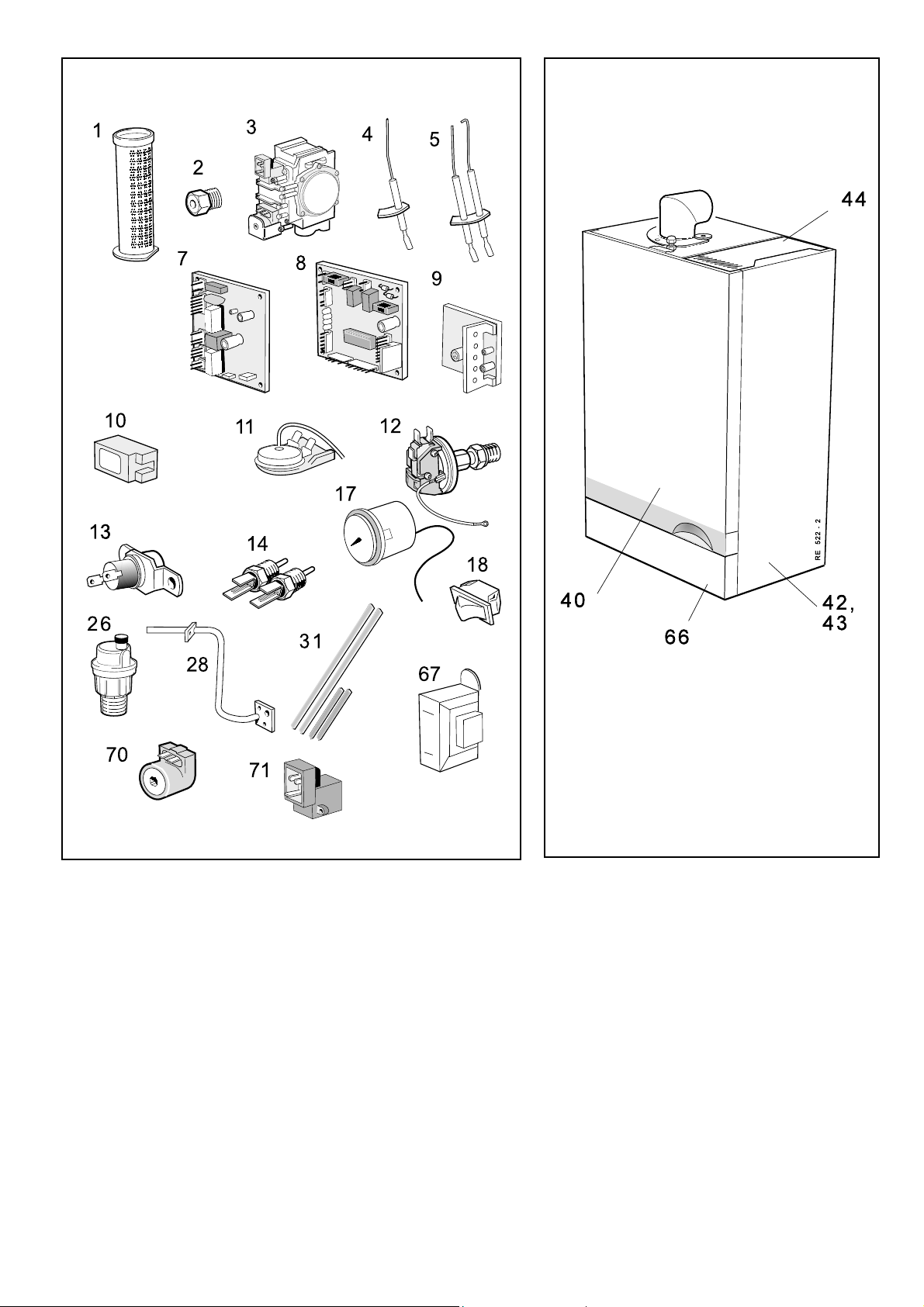
89
SHORT PARTS LIST
SHORT LIST OF PARTS
90
BOILER CASING ASSEMBLY
Res 5972
Response 80 / 100 / 120
- Installation
61
Page 62

NOTES
62
Response 80 / 100 / 120
- Installation
Page 63

NOTES
Response 80 / 100 / 120
- Installation
63
Page 64

The code of practice for the installation,
commissioning & servicing of central heating systems
Technical Training
The Ideal Boilers Technical Training Centre offers a series
of first class training courses for domestic, commercial and
industrial heating installers, engineers and system
specifiers.
For details of courses please ring: ............ 01482 498 432
CERTIFIED PRODUCT
Manufactured under a BS EN ISO 9001: 1994
Quality System accepted by BSI
Ideal Boilers,
HU5 4JN. Telephone: 01482 492 251 Fax: 01482 448 858.
Registration No. London 322 137.
Caradon Ideal Limited pursues a policy of continuing
improvement in the design and performance of its products. The
right is therefore reserved to vary specification without notice.
P.O. Box 103, National Ave, Kingston upon Hull,
I
deal Installer/Technical Helpline: 01482 498663
www.idealboilers.com
April 2003 UIN 152 318 A12
 Loading...