How it Works
Log In / Sign Up
Buy Points
How it Works
FAQ
Contact Us
Questions and Suggestions
Users
ideal
Loading...
M
Mexico Super 100 FF
Mexico Super 40 FF
Mexico Super CF 3/100
Mexico Super CF 3/100P
Mexico Super CF 3/140P
Mexico Super CF 3/40
Mexico Super CF 3/60P
Mexico Super CF 4120
Mexico Super CF 445
Mexico Super FF 4100
Mexico Super FF 440
Mexico Super RS 3/100
Mexico Super RS 3/100P
2
Mexico Super RS 3/40
Mexico Super RS 3/60P
Mexico Super RS 4100
Mexico Super RS 440
Mini C24
2
Mini HE C24
MiniLite-Strip
Minimiser FF 30
N
ND 1075-1
ND-1735
ND2291
ND2292
ND2350
ND2351
ND2353
ND2354
ND2356
ND2365
ND2366
ND2385
ND2396
ND2838
ND-3410
ND 3860-2
ND 4950-3
ND 4960-2
ND 4969-2
ND5435
ND 5481-4
ND–5499
ND-7609-3UK
Networks Navitek IE
NF 230
NF 240
NF 250
NF 260
NF 280
NF 30
NF 40
NF 50
NF 60
NF 70
NF 8О
O
Optia FF 100
Optia HE 12
OTDR
P
PowerBlade
PowerBlade 35-078
PowerBlade 750
PRAKTIK MIG 200 IGBT MMA
R
RD109
RD112
RD115
RD118
RD121
RD124
RD130
Response 100
Response FF80
Response SE
2
RF
RF Electronic
RPS2000
RS1800
RS 230
RS 240
RS 250
RS 260
RS 275
RS30
RS30l RS40
RS 330
RS 340
RS 350
RS 360
RS40
RS 50
2
RS60
S
S15
S18
S24
S30
SCC1000
SCD1000
SCD1000EM
SCD1001
SCD1002
Loading...
Loading...
Nothing found
NF 30
User guide
32 pgs
10.94 Mb
0
Table of contents
Loading...
ideal NF 30, NF 40, NF 50, NF 60, NF 70 User guide
...
ideal NF 30, NF 40, NF 50, NF 60, NF 70, NF 8О User guide
Download
Specifications and Main Features
Frequently Asked Questions
User Manual
Download
Page 1
Page 2
Page 3
Page 4
Page 5
Page 6
Page 7
Page 8
Page 9
Page 10
Page 11
Page 12
Page 13
Page 14
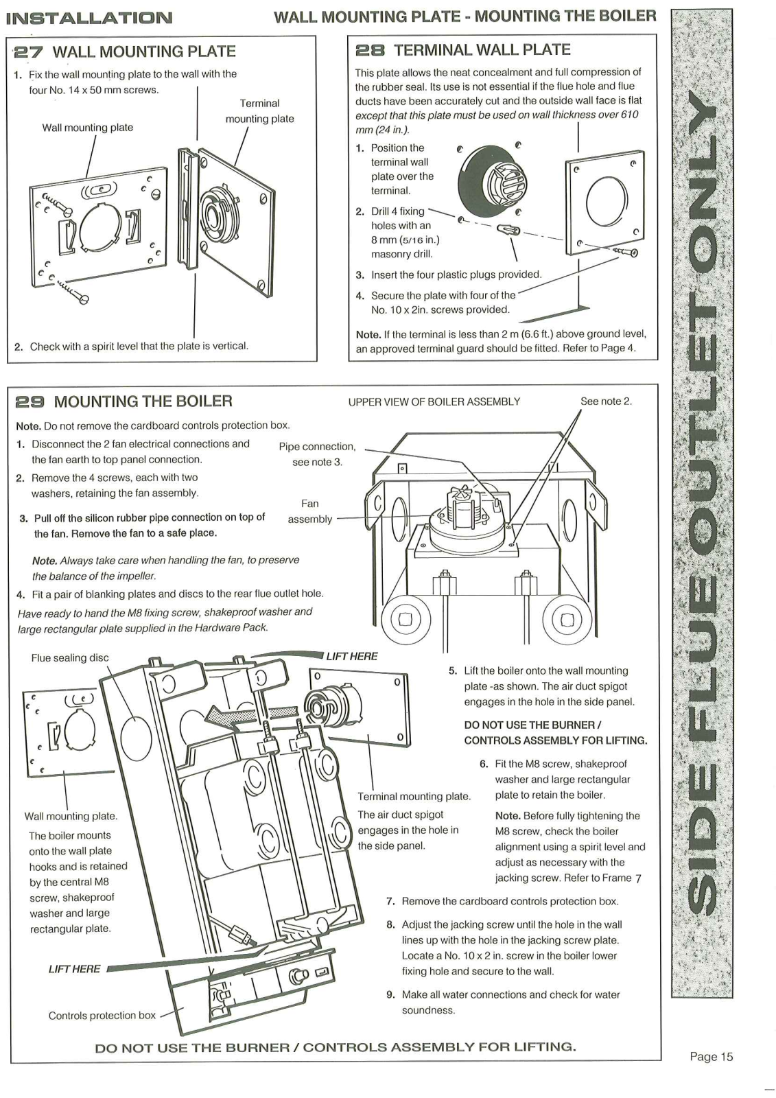
Page 15
Page 16
Page 17
Page 18
Page 19
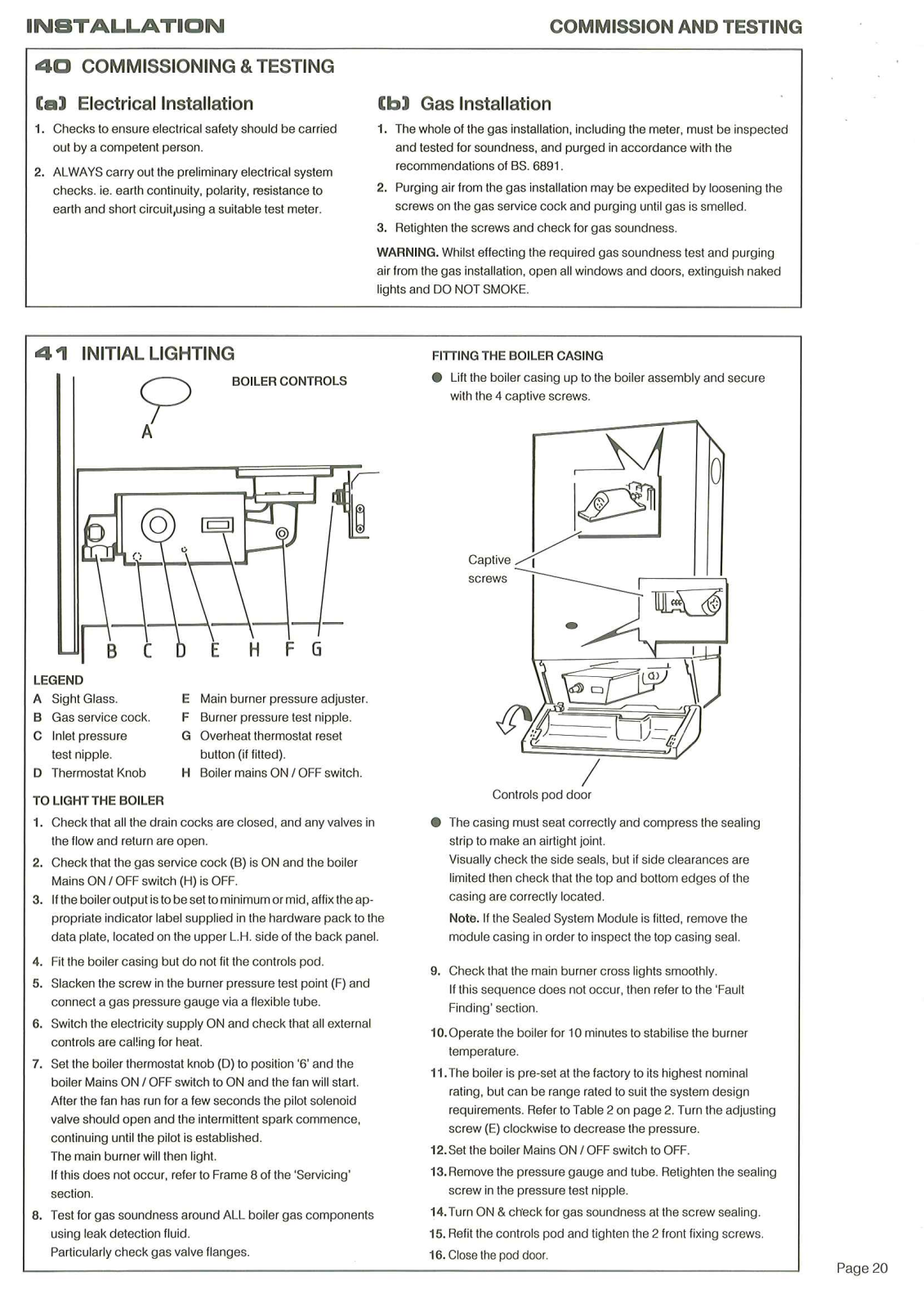
Page 20
Page 21
Page 22
Page 23
Page 24
Page 25
Page 26
Page 27
Page 28
Page 29
Page 30
Page 31
Page 32
Loading...
+
hidden pages
Unhide
You need points to download manuals.
1 point = 1 manual.
You can buy points or you can get point for every manual you upload.
Buy points
Upload your manuals