

Page 1
#ThermalVision™ PRO SW
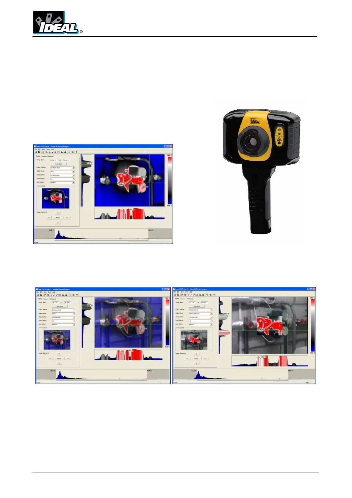
ThermalVision™ PRO PC Software
Instruction Manual
© 2011 IDEA L INDUSTR IES, INC . No part of this pu blication ma y be reprodu ced without pr ior perm iss ion in wri tin g fro m ID EAL. Wh ile
IDEAL will endeavor to ensure that any data contained in this product infor mation is correc t, IDEA L does not warrant its accuracy or
accept liability for any reliance on it. IDEAL reserves the right to change the specification of the products and descriptions in this
publication without notice. Prior to ordering products please ch eck with IDEAL for curre nt specification details. A ll brands and product
names are acknowledged and may be trademarks or registered trademarks of their respective holders.
ND-7609-3UK Page 1 of 21
Page 2

#ThermalVision™ PRO SW
Contents
1. Installing the ThermalVision™ PRO series software onto a PC. ................................... 3
2. Transferring saved images from the camera to the PC. ............................................. 3
2.1. Direct from Camera ........................................................................................ 3
2.2. From Micro-SD Card ........................................................................................ 4
3. Using the ThermalVision™ PRO series software. ....................................................... 4
3.1. Starting the Software. ..................................................................................... 4
3.2. Opening an image. ......................................................................................... 4
3.3. Analysis Tools ................................................................................................ 6
3.4. Menus and Toolbar s ...................................................................................... 11
4. Report Writer ..................................................................................................... 17
4.1. Title Page .................................................................................................... 17
4.2. Image tab.................................................................................................... 18
4.3. Inspection data tab. ...................................................................................... 20
ND-7609-3UK Page 2 of 21
Page 3
#ThermalVision™ PRO SW
1. Installing the ThermalVision™ PRO series software onto a PC.
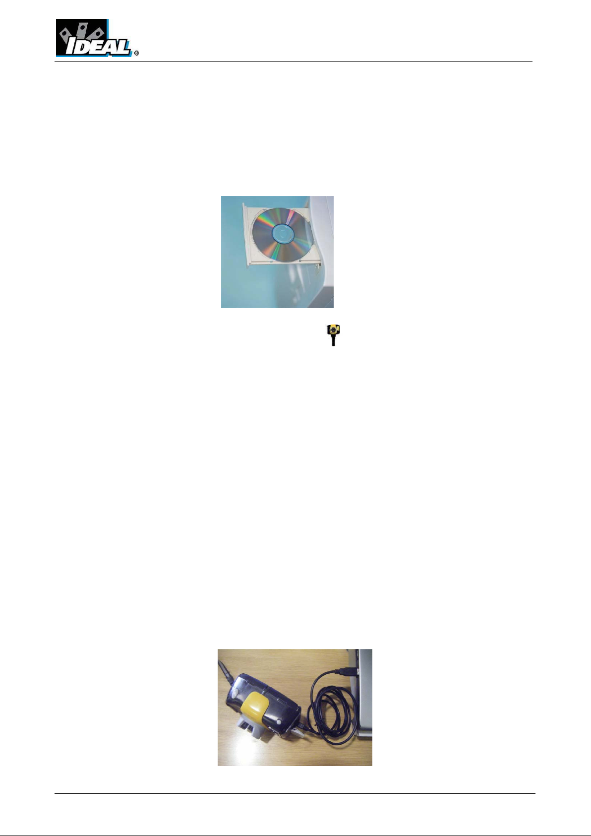
To install the ThermalVision™ PRO software onto a PC:
1. Insert the CD into the PC.
2. Use Windows Exp lorer to view the files on the CD.
3. Open and run the file “ThermalVision PRO PC setup.exe”.
4. This will install the software on to the PC.
Once the software has successfully been installed an
icon appears on the PC Desktop.
2. Transferring saved images from the 61-846 or 61-848 camera to the PC.
In the camera the images are saved on a micro-SD card and are in folders. A new folder is
created every time the camera is switched on. The folder also contains the voice message file
if it is recorded. Each saved image will therefore consist of two or three files.
a. A BMP file containing the thermal and visual image.
b. An IR5 file containing the temperature data.
c. A WAV file if a voice recording was made when the image was saved.
Note: Do not use the Microso ft Scanner and Camera Wizard to download images.
Use Windows Explorer.
There are two ways to transfer images to the PC.
2.1. Direct from Camera
a) Connect the camera to the PC via the USB cable.
b) Use Windows Explorer and filing system to locate the micro-SD card in the camera.
This will nor mally be shown as a removable disk.
c) Copy the complete folders from the micro-SD card on to the PC. Note that there
are at least two files for each image, which must be kept together.
ND-7609-3UK Page 3 of 21
Page 4
#ThermalVision™ PRO SW
2.2. From Micro-SD Card
a) Take the micro-SD card out of the camera and insert into a suitable card reader.
b) Connect the card reader to the PC.
c) Use Windows Explorer to locate the files with the images on the micro-SD card and
copy the complete folders on to the PC. Note that there are at least two files for
each image, which must be kept together.
3. Using the ThermalVision™ PRO s er ies so ft w a r e.
The PC software has two main parts.
1. Analysis Mode – Allows the user to analyse the image and also alter the settings for
how the image is displayed.
2. Report Writer Mode - Allows the user to create a report of the thermal images for
records and administration and opera tional use.
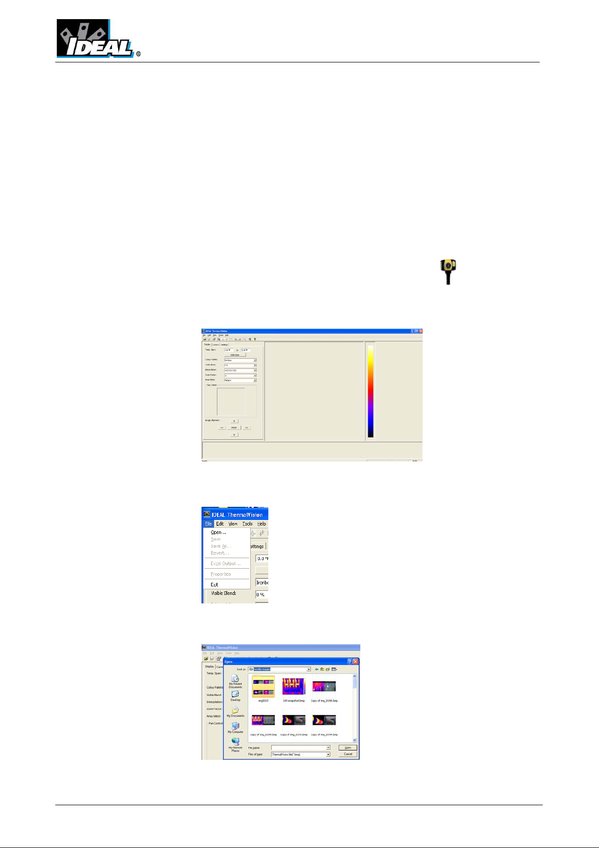
3.1. Starting the Software.
Double Click on the ThermalVision™ PRO series icon to start the software .
The following window will appear.
Note it may be necessary to maximise the window.
3.2. Opening an image.
Click on the drop down File menu and click on “Open”.
Use the Win d ows Exp lorer to locate the folder where the images are saved. If viewing images
directly from the camera this will be shown as a removable disk.
Once the folder is located, double click on the image to be loaded.
ND-7609-3UK Page 4 of 21
Page 5
#ThermalVision™ PRO SW
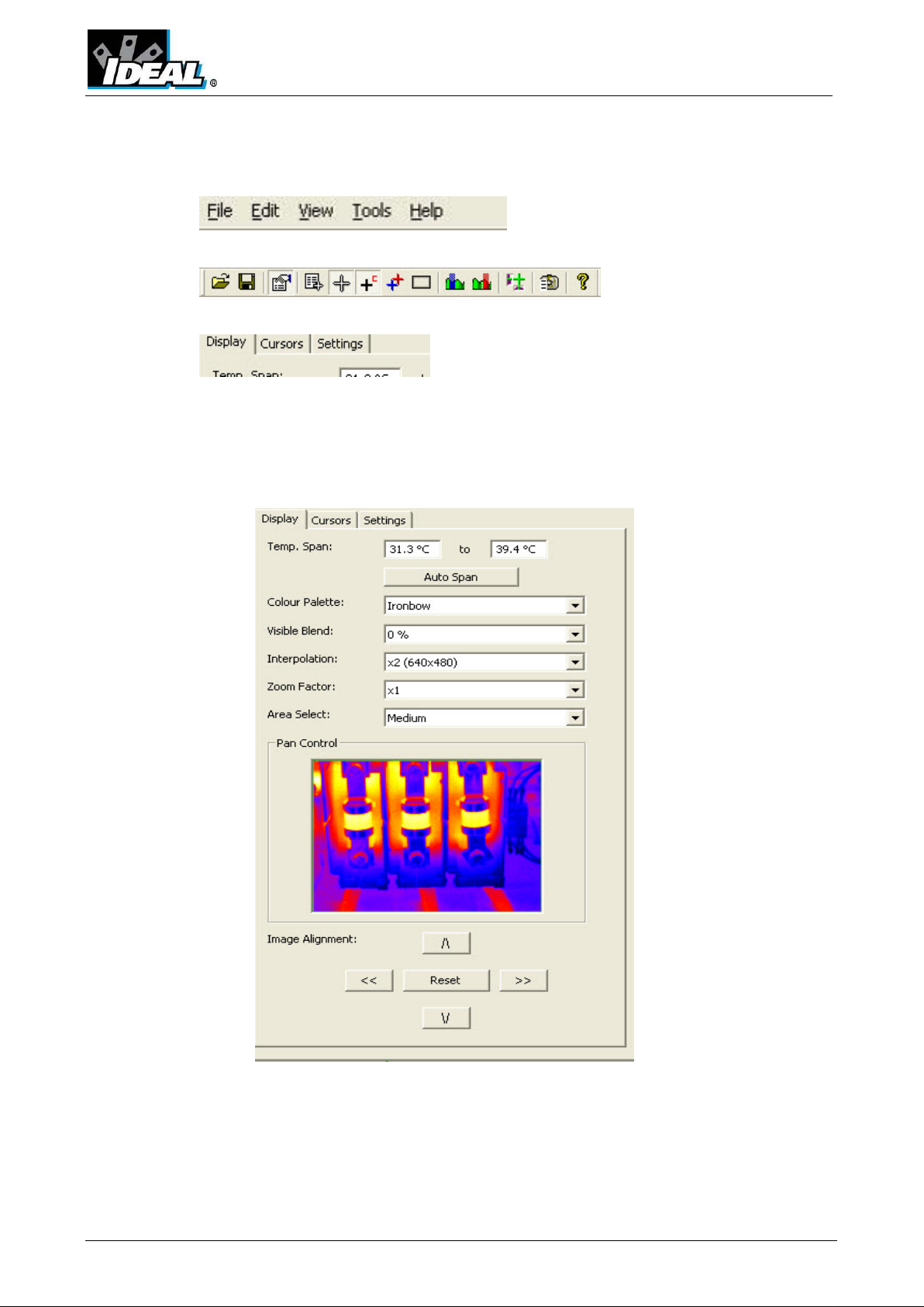
Opening Screen shot.
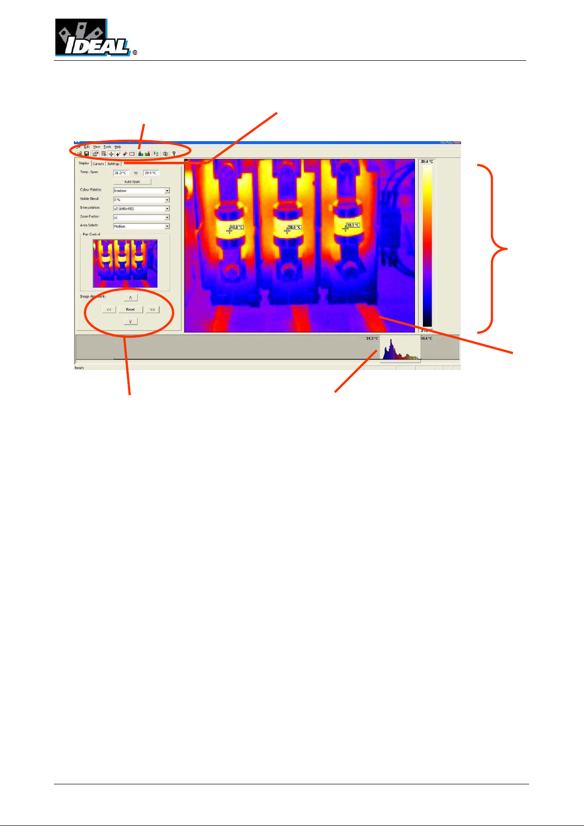
The window format shown below should be displayed. It may be necessary to maximise the
window in order to see all the features.
Toolbar
Image Descript ion
The thermal image i s seen on t he right hand side of the screen. A temperature scal e relati ng
to the colours is displayed to the right of the image. An adjustable span, also showing a
histogram of temperatures in the image is shown at the bottom of the screen. The re is a d rop
down menu bar and an icon toolbar. A set of Tabs is on the left hand side of the image. On
start up the display tab is shown.
Visible and thermal
image alignment
Tabs for Display, Cursors, Settings
and Annotation
Temperature
scale for the
image
Image
Level and Span Adjustment bar
ND-7609-3UK Page 5 of 21
Page 6
#ThermalVision™ PRO SW
3.3. Analysis Tools
To analyse an image and change its presentation the tools available are:
1. Drop down menus.
2. Icon Toolbar.
3. Tabs.
TABS
Display Tab
ND-7609-3UK Page 6 of 21
Page 7
#ThermalVision™ PRO SW
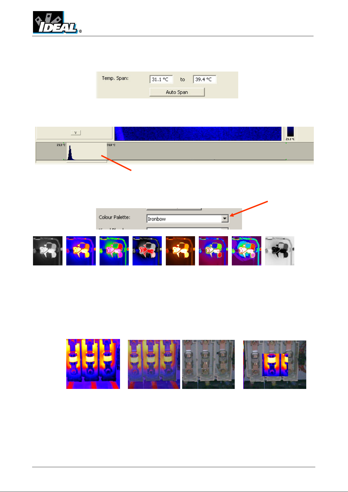
1. Temperature span allows the image display span values to be alt ered manually
by clicking on the Figures in the b oxes and changing them. Auto span set s the
temperature span values based on the temperature values in the image.
The temperature span can also be adjusted using a mouse in the level and span
adjustment bar (see below). To adjust span click on the dark grey and light grey
border and drag. To adjust level click in the middle of the light gre y area and
move.
Level and span
adjustment bar.
2. Colour palette. To change the col our palette, click on the arrow button.
1 2 3 4 5 6 7 8
1. White Hot Mono.
2. Ironbow.
3. Rainbow.
4. Isotherm Style.
5. Hot Met al.
6. High Contrast.
7. 16 step Rainbow.
8. Black Hot Mono.
3. Visible blend. To change the visible/infrared ratio click on the arrow button.
0% Thermal. 50% Thermal 100% Visible. Picture in picture
50% Visible
ND-7609-3UK Page 7 of 21
Page 8

#ThermalVision™ PRO SW
4. Interpolation. To change the interpolation click on the arrow button.
x 1 (320X240) x 2 (640 x 480)
5. Zoom factor. To change the zoom setting click on the arrow button. The
following four settings are available X1, X2, X3, X4
(examples of X1, X2 and X4 shown below).
x1 Zoom X3 Zoom X4 Zoom
When zoomed to x2 or more, the part of the image diplayed can be selected by
means of the mouse in the Pan Control box.
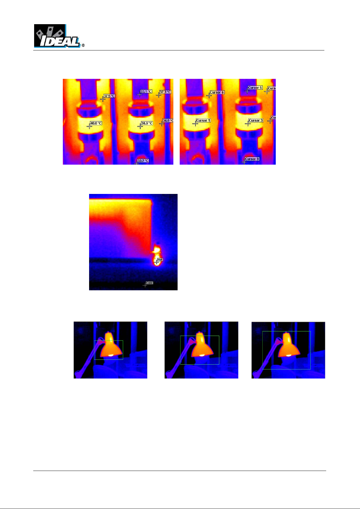
6. Area Select. Use the arrow button to select a small, medium, or large area for
measurement (see page 14).
7. Image alignment. This allows the vertical and horizontal alignment of the
thermal and visible images. Clicking on the navigation arrows will move the
visible i mag e whi le t he in frar ed i ma ge remai n s st ati on ary. It is easiest to adjust
with a 50% thermal and 50% visible image.
Note: Clicking on the reset button returns the alignment to the setting when the file
was opened.
ND-7609-3UK Page 8 of 21
Page 9

Cursors tab
Up to 10 cursors can be added to the display.
The list of cursors within the box shows:-
#ThermalVision™ PRO SW
8. To add a cursor to the image, double click o n the image on the screen.
The cursor can be moved by the drag and drop method.
9. To rem ove cursors either double click on it or highlight the cursor in the box and
click remove.
1. The temperature of the cursors.
2. The position of those cursors.
3. The emissivity value. This can be set individuall y.
a. Select the cursor by clicking on its name in the table.
b. Then either click on the double arrow on the side to call up the
emissvity look up table.
c. Or use the emissivity value box adjustment box and then click on the
set button.
Emissivity Setting Look up table
ND-7609-3UK Page 9 of 21
Page 10

Settings tab
#ThermalVision™ PRO SW
1. Units:
2. Reflected Temp.: Change using the arrow butto ns.
3. Global Emissivity: 0.01 to 1.00. Change using the arrow buttons or
4. Capture Time: Change if required us ing the a rro w buttons.
5. Capture Date: Change if required using the arrow buttons.
6. Comments: Type in any comments in the box.
7. Caption Any text caption typed when saving the image will appear
8. Voice annotation Voice notes recorded when saving the image can be
o
C, oF, K. Change using the arrow button.
>> button. Access the emissivity look up table
here.
replayed via the play button. These can be heard from the
PC’s speakers.
ND-7609-3UK Page 10 of 21
Page 11

#ThermalVision™ PRO SW
3.4. Menus and Toolbars
Use either the drop down menus or the icons on the toolbar to carry out various op e rat ions.
Drop down menus
Icons toolbar.
File
Items 1 and 2 below are also available via the icons on the toolbar.
1. Open. Use Windows Explorer to open an image.
2. Save. To save changes to the image.
3. Save As. To save the image with a different file name.
4. Revert. To discard all changes since the last save.
5. Excel output. Selecting this provides the temperatu r e va lues of all pi xel s in a CSV
format allowing it to be saved as a file. This can then be read as an Excel
spreadsheet. Note that the file must be opened from within the Excel application
(not by “double-clicking” on the file) and selecting comma delimite rs.
ND-7609-3UK Page 11 of 21
Page 12

Edit
#ThermalVision™ PRO SW
1. Copy…
2. Copy To Bitmap…
This offers the option to copy the ima ge to the clipboard or to save as a bitmap. Both
of these options will allow three choices - Full window, Snapshot or Snapshot+.
Full window.
Full window saves the complete
window.
Snapshot.
Snapshot saves the
image only.
Snapshot +.
Snapshot + saves the
image and the colour
temperature scale.
ND-7609-3UK Page 12 of 21
Page 13

View
#ThermalVision™ PRO SW
Items 3 onwards are also available via the icons on the toolbar.
1. Toolbar. Turns on/off the icon toolbar.
2. Status Bar. Turns on/off the status bar at the bottom of the screen.
3. Measu rement Cursors List. Toggles to show the t emperature val ue and positi on
of the selected cursors. The value of the hottest and coldest points in the image
(see item 5 below) and the area box values (item 6 below).
4. Measurement Cursors. Toggles between displaying or removing the cursor/s on
the image.
Cursors on image No Curs ors.
ND-7609-3UK Page 13 of 21
Page 14
#ThermalVision™ PRO SW
5. Cu rso r Tem perature. Toggles between displaying cur sor /s with temperature
values besides them or the cursor number.
6. Hot & Cold Cursors. Allows the display of the hottest and coldest point of the
whole image.
7. Area Select. Selects an area in the middle of the image. The maximum,
minimum and average temperatures of the area box are displayed in the cursor
list (item 3 above). Three different area sizes are available (see page 8).
Small Area Medium Area Large Area
ND-7609-3UK Page 14 of 21
Page 15

blocks in the level and span
To adjust level click in the colour
The temperature difference
between the centre of the two
isotherms is displayed at the
#ThermalVision™ PRO SW
8. Blue Isotherm.
9. Red Isotherm.
Isotherms are r egions within the scene of the same temperature range and are
shown in the same colour. This i s best seen u sing either the white hot or Black
hot colour schemes.
Red Isotherm Blue isotherm Both Isotherms
The red and blue isotherms ca n be
set by adjusting the red and blue
adjustment bar. This can be done
using a mouse.
To adjust the isotherm width, click
on the colour block edge and drag.
block and move.
bottom.
10. Profiles. A temperature profile is a histogram showing the temperature values
through a cross-section of the scene. The profiles are displayed as shown below.
The cross-section lines can be moved by the user.
ND-7609-3UK Page 15 of 21
Page 16

Tools
#ThermalVision™ PRO SW
11. Options. Toggles to display the Tabs panel.
Options on – Tabs displayed Option off
12. Report Writer. This will toggle between the Analysis Mode and Report Writer
Mode.
Help
1. Res et Is ot h e rm s. Reset the isotherms to the default values.
2. Language. The following languages can be selected. Once a language is selected
exit the IR series software and re-start it to activate the selection.
About. Shows the software version.
160
ND-7609-3UK Page 16 of 21
Page 17

#ThermalVision™ PRO SW
4. Report Writer
It is possible to toggle between the ThermalVision™ 160 Analysis Mode and the Report Writer
Mode from the drop down view menu or the toolbar.
There are three steps to create a report. There is a separate tab for each function.
1. Title page. Enter details that should appear in the title page of the repor t.
2. Image select. This allows the selection of the images needed for the report.
3. Inspection Data. Information and additional data about each image can be added
and then the report can be generated.
4.1. Title Page tab
1. When the Report Writer Mode is opened the title page appears as shown above. There is
an empty space where a logo or other image can be placed to appear on the front page of
the final report.
2. Press the select image button.
3. Windows Explorer can now be used to find an image.
4. Click on the open button to select a nd place an image or logo in the title page.
Enter the rest of the details required for the front page of the report.
ND-7609-3UK Page 17 of 21
Page 18

#ThermalVision™ PRO SW
4.2. Image select tab.
1. The screen shown below appears.
2. Click on the browse button to open Windows Ex p lorer.
3. Highlight an image and click on the open button, or simply double click on a IR series
image.
ND-7609-3UK Page 18 of 21
Page 19

#ThermalVision™ PRO SW
4. All the Images in that folder will now appear in the browser selection on the left of the
window.
5. Click on a selected image in the browser section and it appears in the image preview
section on the right of the window.
6. The add/add all remove/remove all buttons allow the selection and removal of images as
required.
7. Selected Image/s will appear in the inspection section in the centre of the window.
ND-7609-3UK Page 19 of 21
Page 20

#ThermalVision™ PRO SW
8. Each image, when selected, may be edited by means of the “Edit Image” button. This
switches to the Analysis Mode. When editing is complete, switch back to the Report
Writer Mode by means of the “Toggle Report Writer” button.
4.3. Inspection Data T ab
1. The inspection Data window will appear.
1. Complete and enter data as required for the report. The image can be edited if required
by clicking on the edit image button.
2. Once data is entered press the Save Project Report button to save the full report. This
allows the report to be edited later if required.
3. Press the Generate PDF Report button when ready to create the report.
4. A report is now generated and can be saved where required.
ND-7609-3UK Page 20 of 21
Page 21

#ThermalVision™ PRO SW
Warranty Statement:
Any implied warranties arising out of the sale of an IDEAL product, including but not limited
warranties of merchantability and fitness for a particular purpose, are limited to the above. The
manufacturer shall not be liable for loss or damage to computer equipment, peripheral
equipment or other incidental or consequential damages, expenses, or economic loss, or for
any claim or claims for such damage, expenses or economic loss.
Country laws vary, so the above limitations or exclusions may not apply to you. This warranty
gives you specific legal rights, and you may also have other rights which vary from country to
country.
IDEAL IN D U STRIES
Unit 3, Europa Court Europa Boulevard
Westbrook, Warrington, WA5 7TN Cheshire, UK
Tel.: +44 (0)1925 44 44 46
Fax: +44 (0)1925 44 55 01
UKsales@idealnwd.com
www.idealindustries.co.uk
www.europe.idealindustries.de
ND-7609-3UK Page 21 of 21
 Loading...