

Page 1
2
#61-802
800 Series
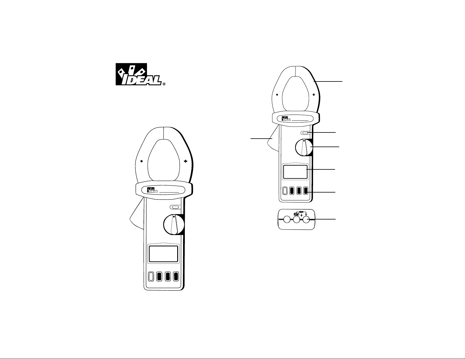
Power Clamp Meter
1. Transformer Jaw
2. Transformer Trigger
3. Data Hold Button
4. Rotary Function Switch
5. LCD Display
6. Function Buttons
7. Input Terminals
1
3
4
5
6
7
2
61-802
Power Clamp
OLD
F
3ØP
C
A
0
0
2
0
0
2
KVARKVA
D
+
0
0
H
C
F
OF
W
K
W
K
F
P
A
V
z
H
VA
3Ø3W
3Ø4W
True RMS
61-802
Power Clamp
OLD
HzV
VA
3Ø4W
PFKW
H
OFF
3ØPF
AC+DC
2000KW
2000A
KVARKVA
3Ø3W
True RMS
Ø
3
DC
A/W
ZERO
READ
KVAR
REC
XT
E
N
KVA
CAT III - 600V
Ø
3
C
D
/W
A
O
R
E
Z
C
D
A
E
R
C
VAR
E
K
R
T
X
E
N
VA
K
V
0
III - 60
T
A
Page 2

43
WARNING!
1. DO NOT UNDER ANY CIRCUMSTANCES EXCEED THESE
RATINGS:
- Voltage is not to exceed 800 Volts.
- Wattage, Resistance and Continuity functions are not to
be performed on circuits capable of delivering greater than
600 Volts.
- Current measurements are not to be performed on circuits capable of delivering greater than 500 Volts
2. To avoid electrical shock hazards and/or damage to the
meter:
- Do not exceed the voltage ratings for the meter. Use
caution when measuring voltage.
- Do not use during electrical storms. AC power sources
with inductive loads or electrical storms may result in high
voltage. High energy transients can damage meter and present a dangerous shock hazard.
- Turn off power to the circuit or device being measured
before taking resistance and capacitance measurements.
Fully discharge all capacitors before measuring.
3. Ensure meter is in proper working order before using.
Visually inspect meter for damage. Performing a continuity
check can verify proper operation. If the meter reading goes
from overload to zero, this typically means the meter is in
proper working order.
4. Visually inspect leads for damage before using. Replace if
insulation is damaged or leads appear suspect.
5. Never ground yourself when taking electrical measurements.
Do not touch exposed metal pipes, outlets, fixtures etc.
Keep your body isolated from ground by using dry clothing,
rubber shoes, mats, or any other approved insulating material. Keep your fingers behind the finger guards on the
probes. Work with others.
6. Before beginning all unknown measurements, set meter to
highest possible range.
7. Before breaking a circuit for testing, turn off the power to the
circuit. When disconnecting from a circuit, disconnect the
hot lead first, then the common lead.
8. Disconnect the meter from the circuit before turning off any
indicator, including motors, transformers, and solenoids.
Data Hold Button
• The data hold button is used to capture and hold a reading
on the LCD display.
• Press the button again to release the reading.
LCD Display
• 3-3/4 digit display with maximum indication of 3999.
• Function symbols, units, analog bargraph, low battery sym-
bol, min/max symbols, relative symbol, and zero symbol are
included.
Function Buttons
DC A/W ZERO Button
• The DC A/W Zero button is used to zero out the DCA residual value.
• Press this button until the LCD displays a zero value and
the zero symbol.
• This button does not force the meter into manual range
mode.
• Press and hold the DC A/W Zero button for 2 seconds to
disable this function.
REC Button
• The meter can store 4 data points in memory.
• Pressing the REC button will store the current value into
memory.
• The data point number (1-4) will be shown on the upper
display, and the stored data will be shown on the main display for approximately 3 seconds.
• After all four data points have been stored, the meter will
display FULL on the secondary display when the REC button is pressed.
• When data is stored in memory, the REC symbol is shown
on the LCD display.
• This data can be viewed by pressing the READ NEXTbutton.
• This data is stored until the meter is turned off.
Page 3
5
3φKVAR KVA Button
• The 3φKVAR KVA button toggles between the KVAR/KVA
measurements and the PF/kW measurements in the 3φ3W
or 3φ4W functions.
• Toggling between these measurements can only be done
after the power clamp has calculated the power factor and
kW measurement.
Read Next Button
In 3φ3W Function
• Pressing the read next button stores the measured values
for kW
RS(L1L2)
/kVA
RS(L1L2)
and moves to the next measurement.
• Pressing read next after the kW
TS(L2L3)
/kVAR
TS(L2L3)
stores the
values and calculates the kW and PF values for the 3φ3W
system.
• After these values have been calculated, press the 3φKVAR
KVA button to display the KVAR and KVA values for the system.
• To start another calculation, press the read next button again
to return and take a measurement for the kW
RS(L1L2)
/kVARS
(L1L2)
values.
In 3φ4W Function
• Pressing the read next button stores the measured values
for W
R(L1)
/PF
R(L1)
and moves to the next measurement.
• Pressing read next after the W
S(L2)
/PF
S(L2)
stores the values
and moves on to the next measurement.
• Pressing read next after the W
T(L3)
/PF
T(L3)
stores the values
and calculates the kW and PF values for the 3φ4W system.
• After these values have been calculated, press the 3φKVAR
KVA button to display the KVAR and KVA values for the system.
• To start another calculation, press the read next button again
to return and take a measurement for the W
R(L1)
/PF
R(L1)
values.
6
In any other function
• Pressing the read next button in any other function displays
the measurement values stored with the REC button.
• The REC NO. symbol will be shown on the LCD display and
the record number will flash on the secondary display to notify the user of what values are being displayed.
• Pressing this button after the meter displays last stored data
point returns to the first stored data point.
• To exit the read next mode, turn the function switch to any
other function. This will exit without losing the stored data.
Kilowatt/Power Factor Measurements
Kilowatt Range Resolution Accuracy Voltage/Current
(AC+DC True Power) Range
0-99.99kW 0.01kW ±(2.0% +0.05) 600VAC, 800VDC
100-999.9kW 0.1kW 2000A AC/DC
1000-1600kW 1kW ±(2.0% +5)
Power Factor 0.2-1.0 for 1φ2W, 1φ3W, 3φ3W, and 3φ4W
Autoranging Table 0-200VAC 200-600VAC
0-200VDC 200-800VDC
0-200A 0.00-40.00kW 0.00-99.99kW
100.0-160.0kW
200-2000A 0.0-400.0kW 0.0-999.9kW
1000-1600kW
61-802
Power Clamp
HOLD
F
3ØP
C
D
+
C
A
F
OF
W
K
0
0
0
2
W
K
F
P
A
0
0
0
2
V
z
H
VA
KVARKVA
3Ø3W
3Ø4W
True RMS
Ø
3
C
D
D
A
E
R
R
A
C
V
E
K
R
W
/
A
T
NEX
A
V
K
O
R
E
Z
V
0
0
6
-
I
I
I
T
A
C
Page 4
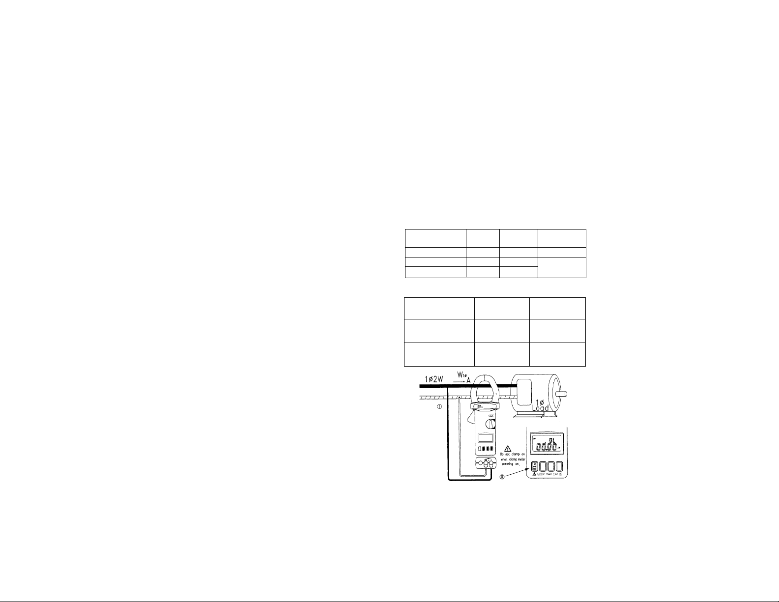
To measure Kilowatts and Power Factor in a single
phase 2-wire system
• Set rotary switch to PF/kW without jaws clamping onto any
wire
• If the watt reading is not zero, press the DC A/W ZERO
button once to zero out the watt reading.
• Insert the black test lead into the COM terminal and the red
test lead into the + terminal.
• Connect the black test probe to the neutral conductor and
the red test probe to the hot conductor.
• Using the trigger to open the jaws, fully enclose the hot
conductor within the clamp.
• Release the trigger and be sure that the jaws have closed
completely.
• The power clamp selects the appropriate range based on the
Autoranging table.
• Power Factor (PF) is a calculated value based on the
formula
PF=_______
• The kW value is shown on the main display and the PF
value is shown on the upper display.
• Positive PF (+) indicates an inductive load, while negative
PF (-) indicates a capacitive load.
8
To measure Kilowatts and Power Factor in a single
phase 3-wire system
See section on 1φ3W AC+DC Power Measurements
AC+DC Voltage/Frequency Measurements
Voltage Resolution Accuracy Accuracy Input
Range (50/60Hz) (40-400Hz) Impedance
0-200V 0.1V ±(1.5% +5) ±(2.0% +5) 10M
200-500V
500-600VAC 1V
500-800VDC
Overload Protection: 800V
TRMS Measurements
Accuracies specified at Crest Factor <3.5
Frequency Range Accuracy Sensitivity
50/60Hz ±(0.5% + 2) >5V
10-400Hz
To Measure Voltage and Frequency
• Set the rotary switch to V/Hz
• Insert the black test lead into the COM terminal and the red
test lead into the + terminal.
• Connect the test probes in parallel with the load or circuit.
• The power clamps automatically selects the proper range.
Note: The “+” sign on the jaw must face the power source for
correct measurement.
kW
kVA
3ØPF
AC+DC
2000KW
2000A
OFF
PFKW
HzV
3Ø3W
3Ø4W
KVARKVA
VA
D
C
A
/
W
Z
E
R
O
R
E
C
3
Ø
K
V
A
R
K
V
A
R
E
A
D
NEX
T
HOLD
CAT III - 600V
P
o
w
e
r
C
l
a
m
p
True
R
M
S
6
1
-
8
0
2
7
Page 5

• The voltage value is shown on the main display and the frequency value is shown on the upper display.
AC+DC Current and Voltage Measurement
AC+DC Current Resolution Accuracy Accuracy
Range (50/60Hz) (40-400Khz)
0-200A 0.1A ±(1.5% +5) ±(2.0% +5)
200-500A ±(2.0% +5) ±(2.5% +5)
500-2000A 1A
Overload Protection: 3000A
TRMS Measurements
Accuracies specified at Crest Factor <3.5
Voltage Resolution Accuracy Accuracy Input
Range (50/60Hz) (40-400Hz) Impedance
0-200V 0.1V ±(1.5% +5) ±(2.0% +5) 10M
200-500V
500-600VAC
500-800VDC 1V
Overload Protection: 800V
TRMS Measurements
Accuracies specified at Crest Factor <3.5
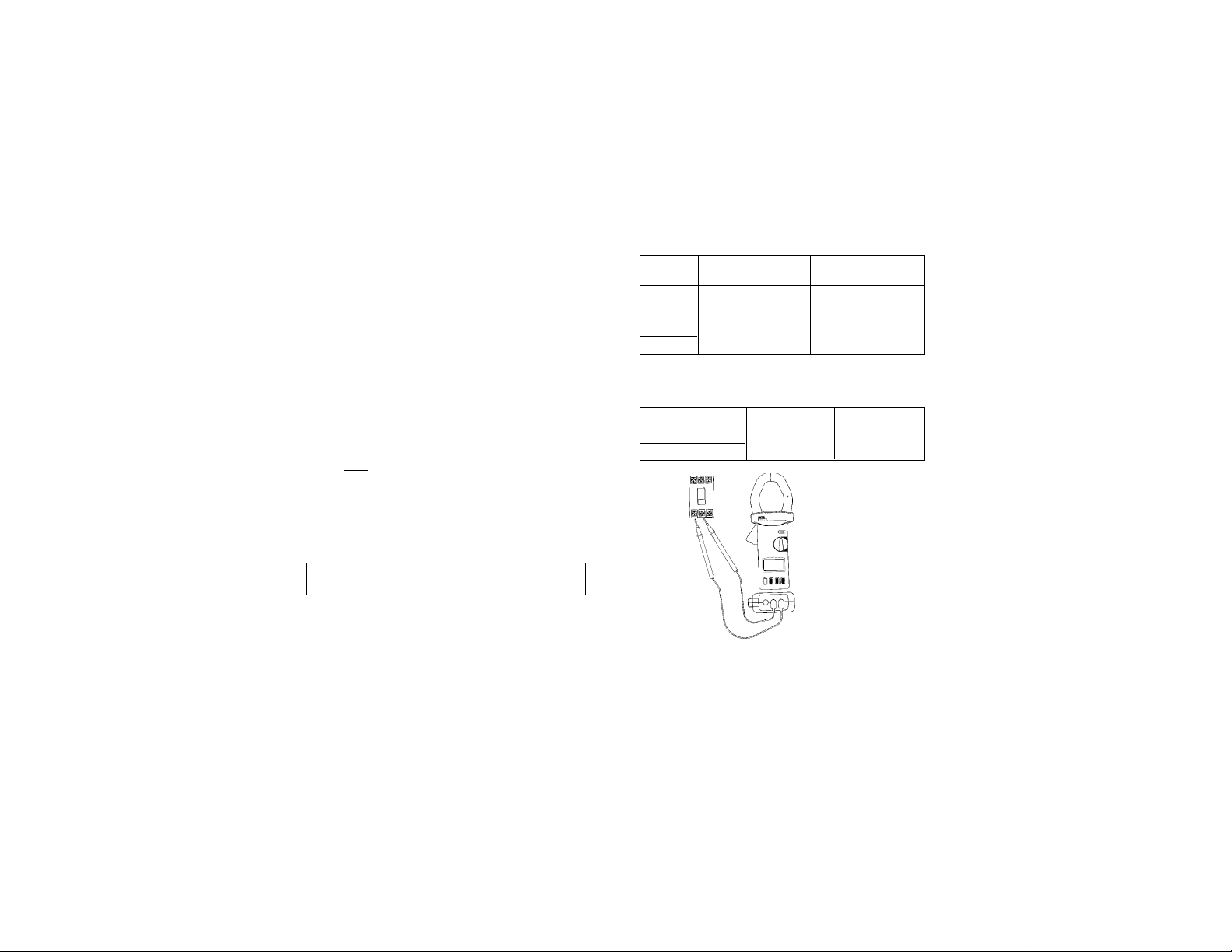
To Measure AC+DC Current and Voltage in a single
phase 2-wire system
• Set rotary switch to A/V
• Press the DC A/W ZERO button to zero the reading
• Using the trigger to open the jaws, fully enclose the con-
ductor within the clamp.
• Release the trigger and be sure that the jaws have closed
completely.
• Insert the black test lead into the COM terminal and the red
test lead into the + terminal.
• Connect the test probes in parallel with the load or circuit.
• The power clamp automatically selects the proper range.
• The current value is shown on the main display and the
voltage value is shown on the upper display.
AC + DC Apparent Power/Reactive Power
Measurement (kVA/kVAR)
10
3ØP
F
A
C
+
D
C
2
0
0
0
K
W
2
0
0
0
A
OF
F
P
F
K
W
H
z
V
3Ø3W
3Ø4W
KVARKVA
VA
D
C
A
/W
Z
E
R
O
R
E
C
3
Ø
K
V
A
R
K
V
A
R
E
A
D
NEX
T
HOLD
C
A
T
I
II -
6
0
0
V
P
o
w
e
r
C
l
a
m
p
True
R
M
S
6
1
-
8
0
2
Note: If the frequency is <10Hz, the display will show 0Hz. If
the frequency is >1000Hz, the display will show OL.
9
Note: Before taking a kVA/kVAR measurement, the DC A/W
ZERO button must be used to zero the current reading. If the
current reading is not zero, the kVA and kVAR values might
be incorrect.
61-802
Power Clamp
HOLD
F
3ØP
C
D
+
C
A
F
OF
W
K
0
0
0
2
W
K
F
P
A
0
0
0
2
V
z
H
VA
KVARKVA
3Ø3W
3Ø4W
True RMS
Ø
3
C
D
D
A
E
R
R
C
A
V
E
K
R
W
/
A
T
NEX
A
V
K
O
R
E
Z
V
0
0
6
-
I
I
I
T
A
C
Page 6

To Measure AC+DC Apparent and Reactive Power
(kVA/kVAR) in a single phase 2-wire system
• Set the rotary switch to A/V.
• Press the DC A/W ZERO button to zero the reading.
• Set the rotary switch to kVA/kVAR.
• Insert the black test lead into the COM terminal and the red
test lead into the + terminal.
• Connect the black test probe to the neutral conductor and
the red test probe to the hot conductor.
• Using the trigger to open the jaws, fully enclose the hot
conductor within the clamp.
• Release the trigger and be sure that the jaws have closed
completely.
• Apparent Power (kVA) is a calculated value based on the
formula
kVA =
• Reactive Power (kVAR) is a calculated value based on the
formula
kVAR =
• To obtain a more accurate kVAR value when the power factor (PF) is greater than 0.91, use the 3φ3W function.
• The kVA value is shown on the main display and the kVAR
value is shown on the upper display.
• Positive kVAR (+) indicates a capacitive load, while negative
kVAR (-) indicates an inductive load.
To measure AC+DC Apparent and Reactive Power
(kVA/kVAR) in a single phase 3-wire system
See section on 1φ3W AC+DC Power Measurements
3φ3W AC+DC Power Measurements
Kilowatt Range Resolution Accuracy Voltage/Current
(AC+DC True Power) Range
0-99.99kW 0.01kW ±(2.0% +0.05) 600VAC, 800VDC
100-999.9kW 0.1kW 2000A AC/DC
1000-1200kW 1kW ±(2.0% +5)
Power Factor 0.2-1.0 for 1
φ
2W, 1φ3W, 3φ3W, and 3φ4W
KVAR Range Resolution Accuracy Voltage/Current
(AC+DC Reactive Power) Range
0-99.99kW 0.01kW ±(2.0% +0.05) 600VAC, 800VDC
100-999.9kW 0.1kW 2000A AC/DC
1000-1200kW 1kW ±(2.0% +5)
In a three phase 3-wire system, the 61-802 power clamp measures
the true power (kW), power factor (PF), apparent power (kVA), and
reactive power (kVAR) of the system. These values are calculated
based on the formulas
kW
3φ3W
= kW
RS(L1L2)
+ kW
TS (L3L2)
PF
3φ3W
=
kVA
3φ3W
=
kVAR
3φ3W
=kVA
RS(L1L2)
+ kVA
RTS(L1L2)
To Measure AC+DC Power Measurements in a three
phase 3-wire system
• Set rotary switch to 3φ3W without jaws clamping onto any
wire.
• The LCD display will show a flashing R to indicate that the
meter is ready for the first measurement.
• If the watt reading is not zero, press the DC A/W ZERO button
once to zero out the watt reading.
• Insert the black test lead into the COM terminal and the red test
lead into the + terminal.
12
VA
1000
(kVA)2- (kW)
2
Note: The “+” sign on the jaw must face the power source for
correct measurement.
11
kW 3φ3W
kVA 3φ3W
kW
2
3φ3W
- kVAR
2
3φ3W
Page 7

13
L1L2 Measurement
• Select one phase to be the common phase. (eg. S or L2)
• Connect the black test probe to the common phase (S or L2)
and the red test probe to another phase (eg. R or L1).
• Using the trigger to open the jaws, fully enclose the phase
(R or L1) within the clamp.
• Release the trigger and be sure that the jaws have closed
completely.
• Wait until the reading is stable, and press the READ NEXT
button to capture the reading, storing the data in memory.
• The LCD display will show a flashing T to indicate that the
meter is ready for the next measurement.
• Remove the clamp and test probes from the phases tested in
the first measurement.
L3L2 Measurement
• Connect the black test probe to the common phase (S or L2)
and the red test probe to the third phase (eg. T or L3)
• Using the trigger to open the jaws, fully enclose the phase (T
or L3) within the clamp.
• Release the trigger and be sure that the jaws have closed
completely.
• Wait until the reading is stable, and press the READ NEXT
button to capture the reading, storing the data in memory.
Calculations
14
Note: Once a phase is selected as common, this selection
cannot be changed. For example, if S or L2 phase is selected, S is always connected to COM during measurement of
W
RS(L1L2)
in 3φ3W unbalanced power.
3ØP
F
A
C
+
D
C
2
0
0
0
K
W
2
0
0
0
A
OF
F
P
F
K
W
H
z
V
3
Ø3W
3Ø4W
KVARKVA
VA
D
C
A
/
W
Z
E
R
O
R
E
C
3
Ø
K
V
A
R
K
V
A
R
E
A
D
N
E
X
T
HOLD
C
A
T
I
I
I
-
6
0
0
V
Power Clamp
True RMS
6
1
-
8
0
2
3ØPF
AC+DC
2000KW
2000A
OFF
PFKW
HzV
3Ø3W
3Ø4W
KVARKVA
VA
DC
A/W
ZERO
REC
3
Ø
K
V
AR
KVA
READ
NE
X
T
HOLD
CAT III - 600V
P
o
w
e
r
C
l
a
m
p
True
R
M
S
6
1
-
8
0
2
3ØPF
AC+DC
2000KW
2000A
OFF
PFKW
HzV
3Ø3W
3Ø4W
KVARKVA
VA
DC
A/W
ZERO
REC
3
Ø
KV
AR
KVA
READ
NEXT
HOLD
CAT III - 600V
P
o
w
e
r
C
l
a
m
p
True
R
M
S
6
1
-
8
0
2
Page 8

15
• The power clamp processes the two sets of data and calculates the true power (kW) of the system, which is shown on
the main display, and the power factor (PF), which is shown
on the upper display. RST is shown on the LCD display to
indicate that this is a measurement of the total system.
• Pressing the 3φKVAR KVA button toggles to display the
apparent power (kVA) of the system, which is shown on the
main display, and the reactive power (kVAR), which is
shown on the upper display.
• Pressing the READ NEXT button clears the stored data from
memory and readies the power clamp for another three
phase 3-wire calculation.
1φ3W AC+DC Power Measurements
The measurements for a single phase 3-wire system are similar
to a three phase 3-wire unbalanced measurements, except the
nomenclature is different.
To Measure AC+DC Power Measurements in a single
phase 3-wire system
• Set rotary switch to 3φ3W without jaws clamping onto any
wire.
• The LCD display will show a flashing R to indicate that the
meter is ready for the first measurement.
• If the watt reading is not zero, press the DC A/W ZERO button once to zero out the watt reading.
• Insert the black test lead into the COM terminal and the red
test lead into the + terminal.
16
L1G Measurement
• Connect the black test probe to ground and the red test
probe to the first phase (R or L1).
• Using the trigger to open the jaws, fully enclose the phase
(R or L1) within the clamp.
• Release the trigger and be sure that the jaws have closed
completely.
• Wait until the reading is stable, and press the READ NEXT
button to capture the reading, storing the data in memory.
• The LCD display will show a flashing T to indicate that the
meter is ready for the next measurement.
• Remove the clamp and test probes from the phases tested in
the first measurement.
L2G Measurement
Note: The “+” sign on the jaw must face the power source for
correct measurement.
Note: In the 3φ3W unbalanced power measurement, one of
WRSor WTScould be negative. Make sure all the connections
and clamping are correct to obtain correct power and power
factor measurements.
3ØP
F
A
C
+
D
C
2
0
0
0
K
W
2
0
0
0
A
OF
F
P
F
K
W
H
z
V
3Ø3W
3Ø4W
KVARKVA
VA
D
C
A
/
W
Z
E
R
O
R
E
C
3
Ø
K
V
A
R
K
V
A
R
E
A
D
NE
X
T
HOLD
C
A
T
I
I
I
-
6
0
0
V
Power Clamp
True RM
S
6
1
-
8
0
2
3ØP
F
A
C
+
D
C
2
0
0
0
K
W
2
0
0
0
A
OF
F
P
F
K
W
H
z
V
3Ø3W
3Ø4W
KVARKVA
VA
D
C
A
/
W
Z
E
R
O
R
E
C
3
Ø
K
V
A
R
K
V
A
R
E
A
D
NE
X
T
HOLD
C
A
T
I
I
I
-
6
0
0
V
Power Clamp
True RM
S
6
1
-
8
0
2
Page 9

1817
• Connect the black test probe to ground and the red test
probe to the second phase (T or L2).
• Using the trigger to open the jaws, fully enclose the phase
(T or L2) within the clamp.
• Release the trigger and be sure that the jaws have closed
completely.
• Wait until the reading is stable, and press the READ NEXT
button to capture the reading, storing the data in memory.
• The power clamp processes the two sets of data and calculates the true power (kW) of the system, which is shown on
the main display, and the power factor (PF), which is shown
on the upper display. RST is shown on the LCD display to
indicate that this is a measurement of the total system.
• Pressing the 3φKVAR KVA button toggles to display the
apparent power (kVA) of the system, which is shown on the
main display, and the reactive power (kVAR), which is
shown on the upper display.
• Pressing the READ NEXT button clears the stored data from
memory and readies the power clamp for another single
phase 3-wire calculation.
3φ4W AC+DC Power Measurements
Kilowatt Range Voltage/Current
(AC+DC True Power) Resolution Accuracy Range
0-99.99kW 0.01kW ±(2.0% +0.05) 600VAC, 800VDC
100-999.9kW 0.1kW 2000A AC/DC
1000-1200kW 1kW ±(2.0% +5)
Power Factor 0.2-1.0 for 1
φ
2W, 1φ3W, 3φ3W, and 3φ4W
In a three phase 4-wire system, the 61-802 power clamp measures the true power (kW), power factor (PF), apparent power
(kVA), and reactive power (kVAR) of the system. These values
are calculated based on the formulas
kW
3φ4W
= kW
3φ4W
= kW
R(L1)
+ kW
S(L2)
+ kW
T(L3)
PF
3φ4W
=
kVA
3φ4W
=
kVAR
3φ4W
=kVAR
R(L1)
+ kVAR
S(L2)
+ kVAR
(TL3)
To Measure AC+DC Power Measurements in a three
phase 4-wire system
• Set rotary switch to 3φ4W without jaws clamping onto any
wire.
• The LCD display will show a flashing R to indicate that the
meter is ready for the first measurement.
• If the watt reading is not zero, press the DC A/W ZERO button once to zero out the watt reading.
• Insert the black test lead into the COM terminal and the red
test lead into the + terminal.
kW 3φ4W
kVA 3φ4W
kW
2
3φ4W
+ kVAR
2
3φ4W
Page 10

20
L1 Measurement
• Connect the black test probe to neutral and the red test
probe to the first phase (R or L1).
• Using the trigger to open the jaws, fully enclose the phase
(R or L1) within the clamp.
• Release the trigger and be sure that the jaws have closed
completely.
• Wait until the reading is stable, and press the READ NEXT
button to capture the reading, storing the data in memory.
• The LCD display will show a flashing S to indicate that the
meter is ready for the next measurement.
• Remove the clamp and test probe from the first phase.
L2 Measurement
• Connect the black test probe to neutral and the red test probe
to the second phase (S or L2)
• Using the trigger to open the jaws, fully enclose the second
phase (S or L2) within the clamp.
• Release the trigger and be sure that the jaws have closed
completely.
• Wait until the reading is stable, and press the READ NEXT
button to capture the reading, storing the data in memory.
• The LCD display will show a flashing T to indicate that the
meter is ready for the next measurement.
• Remove the clamp and test probe from the second phase.
L3 Measurement
• Connect the black test probe to neutral and the red test probe
to the third phase (T or L3)
• Using the trigger to open the jaws, fully enclose the third
phase (T or L3) within the clamp.
• Release the trigger and be sure that the jaws have closed
completely.
• Wait until the reading is stable, and press the READ NEXT
button to capture the reading, storing the data in memory.
3ØP
F
A
C
+
D
C
2
0
0
0
K
W
2
0
0
0
A
OF
F
P
F
K
W
H
z
V
3Ø3W
3
Ø
4W
KVARKVA
VA
D
C
A
/
W
Z
E
R
O
R
E
C
3
Ø
K
V
A
R
K
V
A
R
E
A
D
NE
X
T
HOLD
C
A
T
I
I
I
-
6
0
0
V
P
o
w
e
r
C
la
m
p
True
R
M
S
6
1
-
8
0
2
3ØPF
AC+DC
2000KW
2000A
OFF
PFKW
HzV
3Ø3W
3Ø4W
KVARKVA
VA
D
C
A
/
W
Z
E
R
O
R
E
C
3
Ø
K
V
A
R
K
V
A
R
E
A
D
NEX
T
HOLD
CAT III - 600V
P
o
w
e
r
C
l
a
m
p
True
R
M
S
6
1
-
8
0
2
3ØPF
AC+DC
2000KW
2000A
OFF
PFKW
HzV
3
Ø3W
3Ø
4W
KVARKVA
VA
D
C
A
/
W
Z
E
R
O
R
E
C
3
Ø
K
V
A
R
K
V
A
R
E
A
D
NE
X
T
HOLD
CAT III - 600V
P
o
w
e
r
C
l
a
m
p
True
R
M
S
6
1
-
8
0
2
19
Page 11

2221
Power Calculations
• The power clamp processes the three sets of data and calculates the true power (kW) of the system, which is shown
on the main display, and the power factor (PF), which is
shown on the upper display. RST is shown on the LCD display to indicate that this is a measurement of the total system.
• Pressing the 3φKVAR KVA button toggles to display the
apparent power (kVA) of the system, which is shown on the
main display, and the reactive power (kVAR), which is
shown on the upper display.
• Pressing the READ NEXT button clears the stored data from
memory and readies the power clamp for another three
phase 3-wire calculation.
Power Factor Corrections
A positive power factor indicates that an inductive load has
brought the power system out of phase. Based on the kVAR
values of the system, capacitors are available to improve the
power factor. By measuring the frequency, phase voltage and
kVAR of the system, you can calculate the capacitive load
required for this correction. Single phase capacitors can be
used in a 1φ2W or 3φ4W systems. Three phase capacitors are
available for 3φ3W and 3φ4W systems.
Determining the Required Capacitor Value
• Measure the kVAR
3φ3W
value of the power system.
• The capacitor value required can be calculated based on the
following equation:
Capacitance (Farad) =
f = frequency rating of the system
V = phase voltage
• It is recommended that the KVAR value of the capacitor be a
little less that the measured value.
General Specifications
Indoor Use
Conductor Size: Cable φ55mm (approx.)
Bus Bar 65mm (D) x 24mm (W)
Battery Type: 9V
Display: 2 x 4 Digits Dual Display LCD
Range Selection: Auto
Overload Indication: OL
Power Consumption: 25mA (approx.)
Low Battery Indication:
Sampling Time: 0.5 sec. (V and A)
1.6 sec. (W)
Operating Temperature: 4°C to 50°C
Operating Humidity: Less than 85% relative
Altitude: Up to 2000M
Storage Temperature: -20°C to 60°C
Storage Humidity: Less than 75% relative
Note: The “+” sign on the jaw must face the power source
for correct measurement.
Note: In the 3φ4W power measurement, all three WRor W
T
or WSmust be positive. If one of the three phases has a
negative power, check the connections and clamping and
re-measure the phase to obtain correct power and power
factor measurements.
kVAR *1000
2π fV
2
Page 12

23
IDEAL INDUSTRIES, INC.
Sycamore, IL 60178, U.S.A.
800-304-3578 Customer Assistance
www.testersandmeters.com
ND 2396-1 Made in Taiwan
General Specifications (Continued)
Indoor Use
Dimension: 271mm (L) x 112mm (W) x 46mm
(H)
10.7” (L) x 4.4” (W) x 1.8” (H)
Weight: 647 g/22.8 oz. (batteries included)
Accessories: Carrying bag x 1
Users manual x 1
9V battery x 1 (installed)
Maintenance
Battery Replacement
Warning
Do not touch or adjust any components inside the clamp
when the back case is removed.
Warning
To avoid electrical shock, remove test leads before opening
the cover. Repairs or servicing not covered in this manual
should only be performed by qualified personnel.
• Turn the power off and remove the test leads from the clamp
meter.
• Remove the screws from the back case.
• Lift and remove the back case.
• Remove the old battery and insert a new 9V batter y.
• Replace the back case, and secure the case screws.
Lifetime Limited Warranty
This meter is warranted to the original purchaser against
defects in material or workmanship for the lifetime of the meter.
During this warranty period, IDEAL INDUSTRIES, INC. will, at
its option, replace or repair the defective unit, subject to verification of the defect or malfunction.
This warranty does not apply to defects resulting from abuse,
neglect, accident, unauthorized repair, alteration, or unreasonable use of the instrument.
Any implied warranties arising out of the sale of an IDEAL
product, including but not limited to implied warranties of merchantability and fitness for a particular purpose, are limited to
the above. The manufacturer shall not be liable for loss of use
of the instrument or other incidental or consequential damages,
expenses, or economic loss, or for any claim or claims for
such damage, expenses or economic loss.
State laws vary, so the above limitations or exclusions may not
apply to you. This warranty gives you specific legal rights, and
may also have other rights which vary from state to state.
the data for future analysis.
 Loading...