

Page 1
MIN/MAX
~Hz PEAK
HOLD
Data Acquisition
2
2
#61-492
490 Series
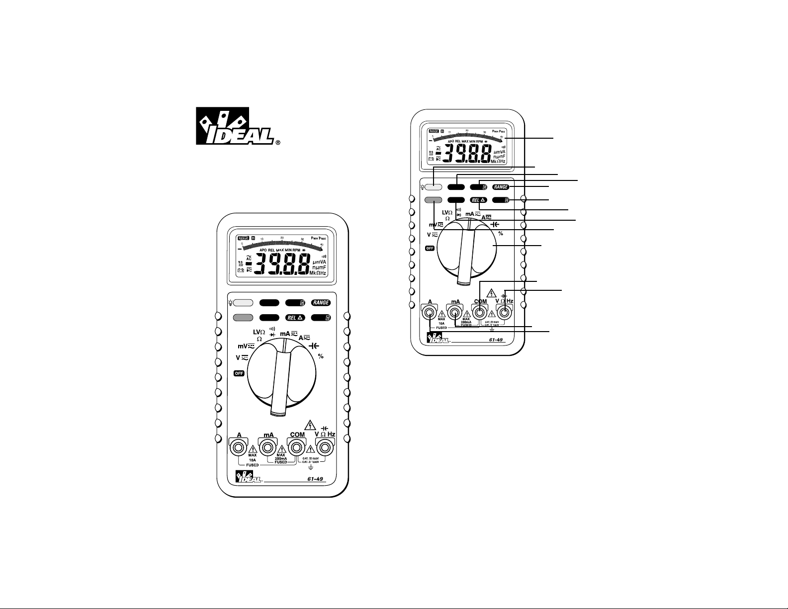
Industrial Grade Multimeter
1. LCD Display
2. Rotary Function Switch
3. COM Input Terminal
4. VΩHz Input Terminal
5. mA Input Terminal
6. A Input Terminal
7. Backlight Button
8. ~Hz Button
9. Peak H Button
10.Range Button
11.Blue Switch Button
12.Min/Max Button
13.REL∆ Button
14.Hold Button
1
10
14
7
2
3
4
5
6
11
12
13
8
9
~Hz PEAK
MIN/MAX
Data Acquisition
HOLD
2
Page 2

4
Function Buttons
The meter beeps once for every valid key-press, and beeps
twice for every invalid key-press.
Backlight Button
• The light button is used to turn the backlight on or off.
~ Hz Button
• Pressing the ~Hz button in AC voltage or current mode
enters frequency counter mode with automatic range
selection.
• Pressing range switch in VAHz mode also changes the full
scale range of the original voltage or current mode after
VAHz mode is cancelled.
Peak Hold Button
• The peak hold button toggles the peak hold function on or
off.
• The precision of peak hold measurement can be enhanced
by calibration.
• Peak hold can be calibrated by pressing the peak hold button for > 2 seconds. “caL will be shown on the main display.
• Press the peak hold button to toggle between PMAX and
PMIN.
• Press peak hold for > 2 seconds to escape the peak hold
measurement.
Range Button
• Pressing the range button changes the unit to manual
ranging and toggles between the ranges of the measurement function.
• Pressing the range button for > 2 seconds returns the unit
to auto ranging.
Blue Button
• The blue button toggles between the black and blue functions on the dial.
3
WARNING!
1. DO NOT UNDER ANY CIRCUMSTANCES EXCEED THESE
RATINGS:
- Voltage is not to exceed 1000 Volts.
- Resistance, Capacitance, Logic and Continuity functions are not to be performed on circuits capable of delivering greater than 600 Volts.
- Current measurements are not to be performed on circuits capable of delivering greater than 500 Volts
2. To avoid electrical shock hazards and/or damage to the
meter:
- Do not exceed the voltage ratings for the meter. Use
caution when measuring voltage.
- Do not use during electrical storms. AC power sources
with inductive loads or electrical storms may result in high
voltage. High energy transients can damage meter and
present a dangerous shock hazard.
- Turn off power to the circuit or device being measured
before taking resistance and capacitance measurements.
Fully discharge all capacitors before measuring.
3. Ensure meter is in proper working order before using.
Visually inspect meter for damage. Performing a continuity check can verify proper operation. If the meter reading
goes from overload to zero, this typically means the meter
is in proper working order.
4. Visually inspect leads for damage before using. Replace if
insulation is damaged or leads appear suspect.
5. Never ground yourself when taking electrical measurements. Do not touch exposed metal pipes, outlets, fixtures
etc. Keep your body isolated from ground by using dry
clothing, rubber shoes, mats, or any other approved insulating material. Keep your fingers behind the finger
guards on the probes. Work with others.
6. Before beginning all unknown measurements, set meter to
highest possible range.
7. Before breaking a circuit for testing, turn off the power to
the circuit. When disconnecting from a circuit, disconnect
the hot lead first, then the common lead.
8. Disconnect the meter from the circuit before turning off
any indicator, including motors, transformers, and solenoids.
Page 3

6
Auto Power Off Feature
• If the meter is idle for more than 30 minutes, power is
automatically turned off.
• The APO annunciator on the display indicates that this feature is enabled.
• To disable this feature, power up the meter while pressing
the MIN/MAX, REL , or Hold button.
• The meter will give an audible indication 15 seconds prior
to powering down the meter.
• Power can be restored, with the display in the saved state
by pressing any of the buttons.
• Power can also be restored by changing the rotary switch.
5
MIN MAX Button
• The MIN/MAX button toggles between the stored minimum, and maximum values.
• Pressing the button the first time displays the minimum
value, the second time displays the maximum value, and
pressing the third time displays the actual measurement
with the MIN and MAX annunciators blinking.
• Pressing hold while in this function stops the meter from
updating the minimum and maximum values.
• To escape this function, press the MIN/MAX button for 2
seconds.
REL Button
• This function displays the differential between the actual
measurement and the last value displayed before pressing
the REL button.
• Pressing the hold button while in this function stops the
display from updating the new differential value.
• Pressing the REL button for >2 seconds enables the
recall function.
Hold Button
• Pressing the hold button stops the meter from updating
the LCD display.
• Enabling the hold function in normal measurement will
switch the meter from auto-ranging to manual ranging, but
will not change the full scale range. The meter can be
returned to auto-ranging by pressing the range, blue or
hold button.
• When the hold button is used in conjunction with the peak
hold, MIN/MAX, or RELr functions, the hold function must
be released by pressing the button prior to returning to
exiting the function.
Overload Protection
Function Overload Protection
VAC & VDC 1000V
AAC & ADC 1A/500V
10A/500V
Ohms (Ω) 600VAC/600VDC
Diode 600VAC/600VDC
Continuity 600VAC/600VDC
Unit of Measure Multipliers
For your reference, the following symbols are often used to
make measurement easier:
Symbol
Verbal Multiplier
M mega x 1,000,000
K kilo x 1,000
m milli ÷ 1,000
µ micro ÷1,000,000
Page 4
8
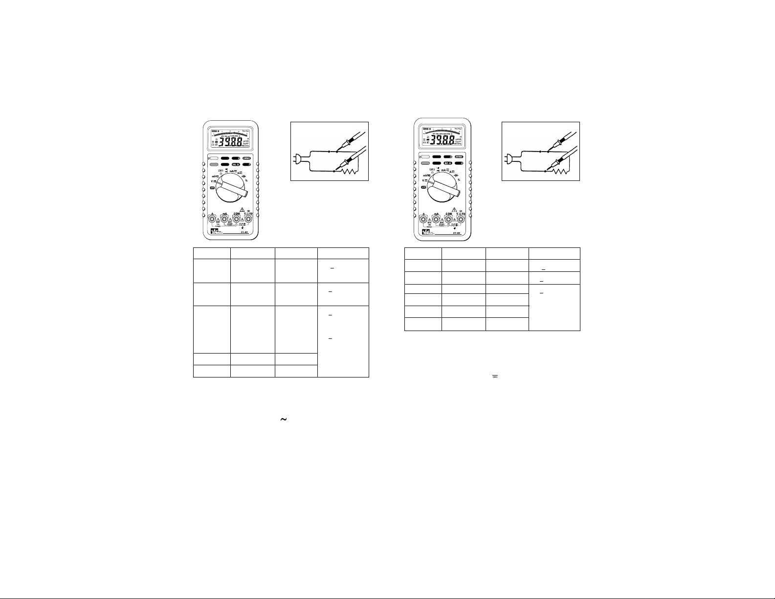
DC Volts
Range Resolution Max Display Accuracy
400mV 0.1mV 400.0 +
(1.5% +8)
400mV 100µV 400.0 +(0.3% +2)
4V 1mV 4.000 +
(0.1% +2)
40V 10mV 40.00
400V 100mV 400.0
1000V 1V 1000
To Measure DC Voltage:
1. Plug the Black test lead into the COM port and the Red
test lead into the Ω port.
2. Set the rotary switch to the V position.
3. Push the blue button until DC is shown on the display.
4. Connect the meter in parallel with the load or circuit.
5. Measure DC Voltage
Input Impedance: 10MΩ (over 1000MΩ in 400mV range)
MIN/MAX
~Hz PEAK
HOLD
Data Acquisition
2
Circuit Connection:
7
AC Volts
Range Resolution Max Display Accuracy
400mV 0.1mV 400.0 +
(1.5% +8)
40Hz ~ 60Hz
4V 1mV 4.000 +(1.0% +5)
40Hz ~ 500Hz
40V 10mV 40.00 +(0.5% +5)
50Hz ~ 60Hz
+(1.0% +5)
40Hz ~ 1kHz
400V 100mV 400.0
750V 1V 750
To Measure AC Voltage:
1. The Plug the Black test lead into the COM port and the
Red test lead into the VΩHz port.
2. Set the rotary switch to the V position.
3. Push the blue button until AC is shown on the display.
4. Connect the meter in parallel with the load or circuit.
5. Measure AC Voltage
Input Impedance: 10MΩ less than 100PF
MIN/MAX
~Hz PEAK
HOLD
Data Acquisition
2
Circuit Connection:
Page 5

DC Current
Range Resolution Max Display Accuracy Voltage
Burden
40mA 10µA 40.00 +
(0.4% +2) 300mV max
400mA 0.1mA 400.0 +
(0.5% +2)
3V max
10A 10mA 10.00 +
(1.0% +3) 3V max
To Measure DC Current:
1. Plug the Black test lead into the COM port and the Red
test lead into the mA or A port.
2. Set the rotary switch to the mA or A position.
3. Push the blue button until DC is shown on the display.
4. Connect the meter in series with the load or circuit.
5. Measure DC Voltage.
Overload Protection: 1A, 600V IR 10kA fuse for mA input
15A, 600V IR 100kA fuse for A input
10
MIN/MAX
~Hz PEAK
HOLD
Data Acquisition
2
Circuit Connection:
AC Current
Range Resolution Max Display Accuracy Voltage
Burden
40mA 1µA 40.00 +
(1.0% +5) 300mV max
400mA 0.1mA 400.0 3V max
10A 10mA 10.00 +(2.0% +5) 3V max
To Measure AC Current:
1. Plug the Black test lead into the COM port and the Red
test lead into the mA or A port.
2. Set the rotary switch to the mA or A position.
3. Push the blue button until AC is shown on the display.
4. Connect the meter in series with the load or circuit.
5. Measure AC Voltage.
Frequency Response: 40Hz ~ 1kHz
Overload Protection: 1A, 600V IR 10kA fuse for mA input
15A, 600V IR 100kA fuse for A input
9
MIN/MAX
~Hz PEAK
HOLD
Data Acquisition
2
Circuit Connection:
Page 6

12
Resistance (Ohms)
Range Resolution Max Display Accuracy
400Ω 0.1Ω 400.0 ±(0.7% +3)
4kΩ 1Ω 4.000 ±(0.4% +2)
40kΩ 10Ω 40.00
400kΩ 100Ω 400.0
4MΩ 1KΩ 4.000 ±(0.6% +3)
40MΩ 10KΩ 40.00 ±(1.5% +5)
To Measure Resistance:
1. Turn the power off to the circuit or device that is to be
measured and discharge all capacitors before attempting a
measurement.
2. Plug the Black test lead into the COM port and the Red test
lead into the VΩHz port.
3. Set the rotary switch to the Ω position.
4. For correct reading, ensure that the device being tested
contains no voltage.
5. Press the range button to select the proper range of the
meter.
Overload Protection: 600V
Open Circuit Voltage: -1.3V (approx.)
MIN/MAX
~Hz PEAK
HOLD
Data Acquisition
2
Circuit Connection:
11
Frequency/RPM
Range Resolution Max Display Sensitivity Accuracy
4kHz/40kRPM 1Hz/30RPM 4.000/40.00 150mV Frequency:
≥2.0 Hz 0.01% +1
1.5V < 20 Hz RPM:
0.01% + 10
40kHz/400kRPM 10Hz/300RPM 40.00/400.0
400kHz/4MRPM 100Hz/3KRPM 400.0/4.000
4MHz/40MRPM 1kHz/30KRPM 4.000/40.00 300mV
40MHz/400MRPM 10kHz/300KRPM 40.00/400.0 1V
400MHz/4000MRPM 100kHz/3MRPM 400.0/4000 ***
*This spec is not guaranteed.
To Measure Frequency:
1. Plug the Black test lead into the COM port and the Red
test lead into the VΩHz port.
2. Set the rotary switch to the HZ RPM position.
3. For RPM, Push the blue button until RPM is shown on the
display.
4. Connect the meter in parallel with the load or circuit.
5. Measure Frequency or RPM.
Overload Protection: 600V
MIN/MAX
~Hz PEAK
HOLD
Data Acquisition
2
Circuit Connection:
Page 7

14
Diode Testing
Function Resolution Accuracy Max. Test Max. Open
Current Circuit
Voltage
1mV +
(1.5% +5) 1.5mA 3V
* For 0.4V to 0.8V.
Diode Check:
1. Turn off power to the device or circuit that is being tested
and discharge all capacitors.
2. Plug the Black test lead into the COM port and the Red
test lead into the VΩHz port.
3. Set the rotary switch to the Ω position.
4. Press the blue button until is shown on the display
5. Connect the test leads to the diode. Normally the forward
voltage drop of a good silicone diode is shown between
400V and 0.9V. If the diode under test is defective, “000”
(short circuit) or “OL” (non-conductive) is displayed.
Overload Protection: 600V max
MIN/MAX
~Hz PEAK
HOLD
Data Acquisition
2
Circuit Connection:
Capacitance
Range Resolution Max Display Accuracy
4nF 1pF 4.000 +
(3.0% +10)
40nF 10pF 40.00 +(3.0% +5)
400nF 100pF 400.0
4µF 1nF 4.000
40µF 10nF 40.00
400µF 100nF 400.0
4mF 1µF 4.000 +
(5.0% +20)*
40mF 10µF 40.00
* In these two ranges the reading may be rolling within specification
To Measure Capacitance:
1. Turn the power off to the circuit or device that is to be measured
and discharge all capacitors before attempting a measurement.
2. Plug the Black test lead into the COM port and the Red test lead
into the VΩHz port.
3. Set the rotary switch to the position.
4. Connect the leads to the circuit to be measured.
5. Measure Capacitance
In order to ensure the best accuracy in measurement of low capacitance,
open the test leads before measurement and
memorize the test probe capacitance. It is necessary to
subtract the capacitance of the test probes themselves, or use the relative mode to compensate for the test leads.
Overload Protection: 600V
13
MIN/MAX
~Hz PEAK
HOLD
Data Acquisition
2
Circuit Connection:
Page 8

16
PEAK Hold Measurements
Function Range Accuracy Function Range Accuracy
DC 400mV unspecified AC 400mV unspecified
Voltage Voltage
4V +
(1.5% +300) 4V +(1.5% +300)
40V +
(1.5% +60) 40V +(1.5% +60)
400V 400V
1000V 750V
DC 40mA +
(3% +60) AC 40mA +(3% +60)
Current Current
400mA 400mA
10A +
(1.5% +60) 10A +(1.5% +60)
Note: With zero calibrated before measurement
4V ranges specify readings above 10% of full scale
Current ranges specify reading <90% of full scale
Noise generating fields may affect intervals
MIN/MAX
~Hz PEAK
HOLD
Data Acquisition
2
Continuity Check
To Verify Continuity:
1. A continuity test ensures that all circuit connections are
intact.
2. Plug the Black test lead into the COM port and the Red
test lead into the Ω port.
3. Set the rotary switch to the Ω position.
4. Press the blue button until is shown in the display.
5. Connect the test leads to the circuit to be measured. The
buzzer will sound if the resistance of the circuit measured
is lower than 30Ω.
15
MIN/MAX
~Hz PEAK
HOLD
Data Acquisition
2
Circuit Connection:
Page 9

18
The function packet indicates the measurement mode of
the meter. Status, option 1 and option 2 gives the status of
the meter. CR and LF are delimiters used to separate the
blocks.
The meter always outputs the current input value to the
serial port. Each block is repeated twice in one conversion
cycle. The detailed data format of each packet is listed
below.
- Function
This packet indicates the measurement mode of the meter.
The following table summarizes the transmitted code for
each mode.
Code Measurement Mode
0111011 Voltage
0111101 µA Current
0111001 mA Current
0111111 A Current
0110011 Ω
0110101 Continuity
0110001 Diode
0110010 Frequency / RPM
1
0110110 Capacitance
Note 1: The judge bit in the Status packet determines whether it is frequency
mode or RPM mode.
17
Data Acquisition Function
1. Auto Power Off (APO)
The APO sign on the LCD panel indicates the meter is
working in the Auto Power Off mode. If the meter idles for
more than 30 minutes, the meter automatically turns the
power off. When this happens, the state (non-logic
measurement) of the meter is saved, the meter can be
turned back on by pushing any key switch, except back
light switch, or changing the rotary switch. If the meter is
Re-Powered on by pushing key switch, the LCD displays
the saved state when meter auto power off itself, pushing
Hold key switch to disable the hold state. The meter will
give periodic alarm in 15 seconds before automatically
turns power off by itself, any key press or rotary change
reset Auto Power Off.
2. Disable Auto Power Off
In order to disable auto power off function, power on the
meter with pressing anyone of the switches, except the
HOLD switch, back light switch or BLUE switch (for
function change) is pressed down.
3. RS232
Sent a single pulse to the multimeter to enable or disable
the RS232 when enable the RS232 the LCD display shows
the RS232 annunciator
The serial data is sent from RS232 cable twice every A/D
conversion cycle. The data format complies with JIS 7BIT
transmission code with a baud rate of 2400. The user can
use RS232 interface to read the data. A single dada packet
includes a start bit (always 0), 7 data bits, an odd parity
check bit, and a stop bit (always 1). The following figure
shows the data format of a single packet. The LSB is sent
first and the MSB is sent last.
One data block consists of 11 packets, or 110 bits. The
following figure shows the format of a data block. The
range packet indicates the full scale range of the meter.
Digit 3 through digit 0 is just the digits on the LCD panel.
Page 10

20
- Digit 3 - Digit 0
Digit 3 i the most significant digit on the LCD panel, and
digit 0 is the least significant digit. When the LCD panel
shows OL, the serial port outputs 4000.
Digit Code
0 0110000
1 0110001
2 0110010
3 0110011
4 0110100
5 0110101
6 0110110
7 0110111
8 0111000
9 0111001
- Status
The format of this packet is shown below. The Judge field
is meaningful only when the Function packet indicates
Frequency / RPM mode.
In Frequency / RPM mode, judge is 1 if the meter operates
in Frequency mode; otherwise, it is 0. Sign field indicates
whether the minus sign on the LCD panel is on or off.
BATT field is 1 if battery low condition is true. OL indicates
input overflow.
0 1 1 Judge Sign BATT OL
Bit 6 Bit 5 Bit 4 Bit 3 Bit 2 Bit 1 Bit 0
19
- Range
This packet indicates the full scale range of the meter.
When the meter operates in continuity mode, diode mode
or current (A) mode, this packet is always 0110000 since
the full scale range in these modes are fixed. The following
table lists the code for each range in each measurement
mode.
Code V mA Ω Frequency RPM Capacitance
0110000 400.0mV 40.00mA 400.0Ω 4.000KHz 40.00KRPM 4.000nF
0110001 4.000V 400.0mA 4.000KΩ 40.00KHz 400.0KRPM 40.00nF
0110010 40.00V 40.00KΩ 400.0KHz 4.000MRPM 400.0nF
0110011 400.0V 400.0KΩ 4.000MHz 40.00MRPM 4.000µF
0110100 4000V 4.000MΩ 40.00MHz 400.0MRPM 40.00µF
0110101 40.00MΩ 400.0MHz 4000MRPM 400.0µF
0110110 4.000mF
0110111 40.00mF
Page 11

22
21
- Option 1
This packet contains information on special measurement
modes. The format of this packet is shown below. The
three non-constant fields is set to one when the meter
operates in the corresponding special modes.
01 1P
MAXPMAX
0 VAHZ
Bit 6 Bit 5 Bit 4 Bit 3 Bit 2 Bit 1 Bit 0
- Option 2
This packet contains information on the operations mode
of the meter. The format is shown below. The DC field
indicates that the meter operates in DC measurements
mode, either voltage or current. The AC field indicates that
the meter operates in AC measurement mode. The AUTO
field is set to 1 if the meter operates in automatic mode,
and is set to 0 when the meter operates in manual mode.
The APO field indicates whether Auto Power Off function is
enabled or not.
0 1 1 DC AC AUTO APO
Bit 6 Bit 5 Bit 4 Bit 3 Bit 2 Bit 1 Bit 0
-CR
Carriage return. The transmitted code is 0001101.
-LF
Line Feed. The transmitted code is 0001010.
CUS
General Specifications
Display: The Liquid Crystal Display (LCD)
with a maximum reading of 4000 and
82 segments bar graph.
Polarity Indication: Automatic, positive implied, negative
indicated.
Over range indication: (OL) or (-OL)
Low Battery Indication: is displayed when the battery
voltage drops below operating
voltage.
Sampling: 2 times/sec for digit.
12 times/sec for analog bargraph.
Auto Power Off: Approx 30 Minutes
Operating Ambient: 0°C - 30°C (≤80%R.H.),
30°C - 40°C (≤75%R.H.),
40°C - 50°C (≤45%R.H.)
Temperature Coefficient: 0.15 x (Spec Acc’y) / °C,
<18°C or >28°C.
Power Requirements: IEC LR03, AM4 or AAA size 1.5V x 2.
Battery Life: Alkaline 500 hours.
Dimensions (WxHxD):
90mmx200mmx42mm,
with out holster
100mmx212mmx55mm, with holster
Accessories: Protective Holster, battery (installed)
instruction manual, test leads.
Environmental Conditions
Indoor use.
Maximum Altitude: 2000 Meter.
Installation Category: IEC 1010, 1000V Cat. II, 600V Cat. III
Pollution Degree: 2
Page 12

23
Lifetime Limited Warranty
This meter is warranted to the original purchaser against defects in
material or workmanship for the lifetime of the meter. During this
warranty period, IDEAL INDUSTRIES, INC. will, at its option,
replace or repair the defective unit, subject to verification of the
defect or malfunction.
This warranty does not apply to defects resulting from abuse,
neglect, accident, unauthorized repair, alteration, or unreasonable
use of the instrument.
Any implied warranties arising out of the sale of an IDEAL product,
including but not limited to implied warranties of merchantability
and fitness for a particular purpose, are limited to the above. The
manufacturer shall not be liable for loss of use of the instrument or
other incidental or consequential damages, expenses, or economic
loss, or for any claim or claims for such damage, expenses or economic loss.
State laws vary, so the above limitations or exclusions may not
apply to you. This warranty gives you specific legal rights, and you
may also have other rights which vary from state to state.
IDEAL INDUSTRIES, INC.
Sycamore, IL 60178, U.S.A.
800-304-3578 Customer Assistance
www.testersandmeters.com
ND 2385-1 Made in Taiwan
Maintenance
Battery Installation or Replacement:
The #61-492 is powered by 2 1.5 volt batteries.
1. Remove the test leads from the front terminals and turn the
meter off.
2. Remove the screw from the battery cover and lift to
remove.
3. Replace batteries.
4. Make sure the battery box leads do not become pinched
between the case and battery cover before replacing the
battery cover and screw.
Fuse Replacement
1. Remove the test leads from the front terminals and turn the
meter off.
2. Remove the screw from the battery cover and lift to
remove.
3. Remove the battery.
4. Remove the two screws connecting the top and bottom
cases of the meter.
5. Remove the defective fuse by gently prying one end of the
fuse loose and sliding the fuse out of the fuse holder.
6. Install a new fuse of the same size and rating.
7. Make sure the fuse is centered in the fuse holder
8. Reconnect the top and bottom case.
9. Re-install the battery and batter y cover.
Warning
To avoid electrical shock, remove test lead before opening the
cover. Repairs or servicing not covered in this manual should
only be performed by qualified personnel.
 Loading...