

Page 1
2
#61-482
480 Platinum Pro Series
Commercial Contractor
Grade Multimeter
True RMS
Symbols in this Manual
This symbol indicates where cautionary or other
information is found in the manual.
Fuse
Battery
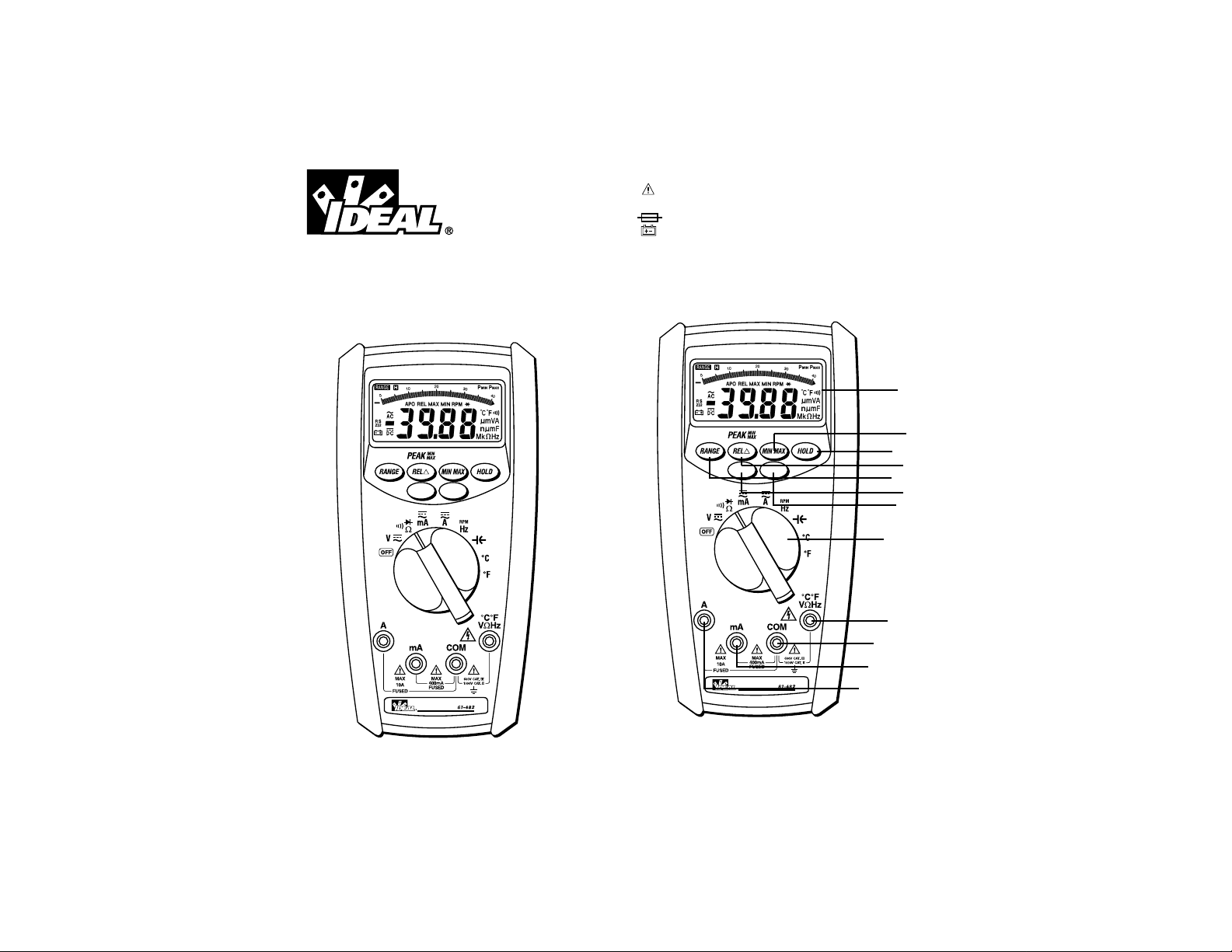
Refer to Figure 1 and to the following numbered steps to
familiarize yourself with the meter’s front panel controls
and connectors.
True RMS
1
4
2
3
5
8
11
12
9
6
10
7
Page 2

43
1. Digital Display – The digital display has 4000 counts
LCD readout with 82 segments analog bar graph, auto
polarity, decimal point, “ ” AC, DC RANGE,
APO and unit annunciators.
2. Rotary Switch – Select the Function and Range desired.
3. COM Input Terminal –Ground input connector.
4. °C °F VΩHz Input Terminal –Positive input connector
for Volts, Ohms Frequency, and Temperature.
5. mA Input Terminal –Positive input connector for Amp
measurements (up to 400mA).
6. A Input Terminal –Positive input connector for Amp
measurements (up to 10A).
7. Range Switch, (Manual Range) – “Range” switch is
pushed to select manual ranging and to change ranges.
When “Range” switch is pushed on “Range” annunciator on
the LCD appears. Push “ Range ” switch to select
appropriate range to be used. Push “Range” switch and
hold 2 seconds to return to Autoranging.
8. REL (PEAK MIN/MAX) Switch – For resistance,
frequency, capacitance and temperature measurements, this
button enables the relative change function. When pressed
the value is stored, and all new measurements are displayed
as their relative difference from the stored value. In current
and voltage measurements, this button performs a peak
hold finction. The peak hold mode must be calibrated prior
to use. To calibrate the peak hold, press the key until the
meter displays “CAL”. Short the test leads to calibrate.
9. MIN/MAX Switch – Press this switch to toggle between
the minimum and maximum values. Pressing the button for
2 seconds to escape MIN/MAX mode.
10.Hold Switch – This switch is used to hold the measured
value for all functions. The held value is displayed along
with the annunciator. Measurements are made ,but the
display is not updated. This function can be used in
MIN/MAX mode or PEAK MIN/MAX mode.
11.Light Switch – This switch turns the backlight on and off.
12.Blue Switch – Push the switch to measure AC
Voltage/Current or DC Voltage/Current in the
Voltage/Current mode, or to measure Resistance or
Continuity or Diode in Ω/ / mode, or to measure
frequency or RPM in Hz/RPM mode.
WARNING!
1. DO NOT UNDER ANY CIRCUMSTANCES EXCEED THESE
RATINGS:
• Voltage is not to exceed 1000 Volts.
• Resistance, Capacitance, Logic and Continuity functions
are not to be performed on circuits capable of delivering
greater than 600 Volts.
• Current measurements are not to be performed on
circuits capable of delivering greater than 500 Volts
2. To avoid electrical shock hazards and/or damage to the meter:
• Do not exceed the voltage ratings for the meter. Use
caution when measuring voltage.
• Do not use during electrical storms. AC power sources
with inductive loads or electrical storms may result in
high voltage. High energy transients can damage meter
and present a dangerous shock hazard.
• Turn off power to the circuit or device being measured
before taking resistance and capacitance measurements.
Fully discharge all capacitors before measuring.
3. Ensure meter is in proper working order before using.
Visually inspect meter for damage. Performing a continuity
check can verify proper operation. If the meter reading goes
from overload to zero, this typically means the meter is in
proper working order.
4. Visually inspect leads for damage before using. Replace if
insulation is damaged or leads appear suspect.
5. Never ground yourself when taking electrical measurements.
Do not touch exposed metal pipes, outlets, fixtures etc.
Keep your body isolated from ground by using dry clothing,
rubber shoes, mats, or any other approved insulating
material. Keep your fingers behind the finger guards on the
probes. Work with others.
6. Before beginning all unknown measurements, set meter to
highest possible range.
7. Before breaking a circuit for testing, turn off the power to the
circuit. When disconnecting from a circuit, disconnect the
hot lead first, then the common lead.
8. Disconnect the meter from the circuit before turning off any
indicator, including motors, transformers, and solenoids.
H
H
Page 3
65
True RMS AC Volt
Range Resolution Max Display Accuracy
400mV 0.1mV 400.0 ±(2.0% +8)
40Hz to 60Hz
4V 1mV 4.000 ±(1.3% +5)
40Hz to 1kHz
40V 10mV 40.00 ±(1.3% +5)
400V 100mV 400.0 40Hz to 1kHz
750V 1V 750
AC Conversion Type:AC conversions are AC-coupled, true
RMS responding, calibrated to the RMS value sine wave input.
Input and Impedance: 10MΩ less than 100 PF.
Crest Factor: +1.5% additional error for C.F. from 1.4 to 3
+3.0% additional error for C.F. from 3 to 4
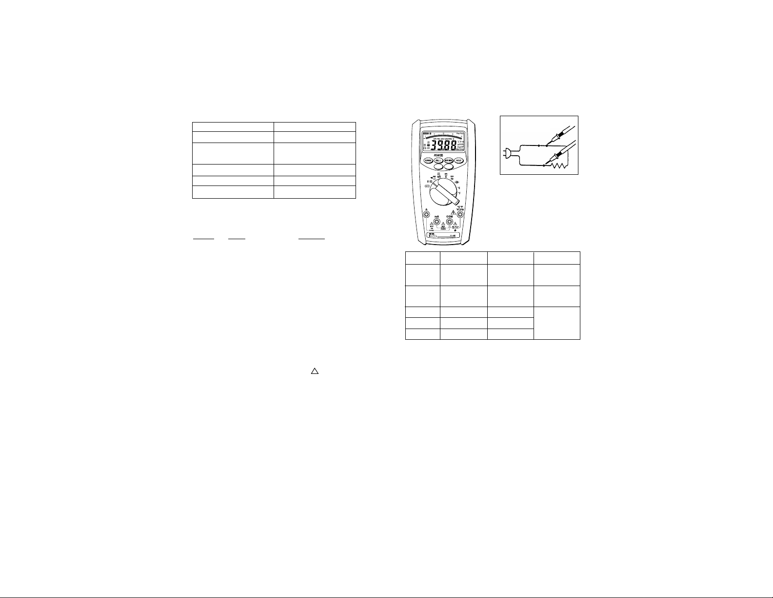
To Measure True RMS AC Voltage:
1. Plug the black test lead into the COM port and the red test
lead into the °C°F VΩHz port.
2. Set the rotary switch to the V position.
3. Push the blue button until AC is shown on the display.
4. Connect the meter in parallel with the load or circuit.
5. Measure AC Voltage.
Overload Protection
Function Overload Protection
VAC & VDC 1000V
AAC & ADC 1A/500V
16A/500V
Ohms (Ω) 600VAC/600VDC
Diode 600VAC/600VDC
Continuity 600VAC/600VDC
Unit of Measure Multipliers
For your reference, the following symbols are often used to
make measurement easier:
Symbol Verbal Multiplier
M mega x 1,000,000
k kilo x 1,000
m milli ÷ 1,000
µ micro ÷ 1,000,000
Auto Power Off (APO)
The APO sign on the LCD panel indicates the meter is working
in the Auto Power Off mode. If the meter idles for more than 30
minutes, the meter automatically turns the power off. When this
happens, the state (non-logic measurement) of the meter is
saved, the meter can be turned back on by pushing any key
switch or changing the rotary switch. The meter will give an
alarm in 15 seconds before the meter automatically turns the
power off. To disable the auto power off function, power up the
meter while pressing either the range, REL or min/max
switch.
˜
Circuit Connection:
True RMS
Page 4
87
DC Volts
Range Resolution Max Display Accuracy
400mV 100µV 400.0 ±(0.25% +5)
4V 1mV 4.000 ±(0.4% +1)
40V 10mV 40.00 ±(0.25% +1)
400V 100mV 400.0
1000V 1V 1000
Input Impedance: 10MΩ (over 1000MΩ in 400mV range)
To Measure DC Voltage:
1. Plug the black test lead into the COM port and the red test
lead into the °C°F VΩHz port.
2. Set the rotary switch to the V position.
3. Push the blue button until DC is shown on the display.
4. Connect the meter in parallel with the load or circuit.
5. Measure DC Voltage
True RMS AC Current
Range Resolution Max Accuracy Voltage
Display Burden
40mA 10µA 40.00 ±(2.0% +5) 200mV max
400mA 0.1mA 400.0 2Vmax
10A 10mA 10.00 ±(2.5% +5) 2V max
AC Conversion Type:AC conversions are AC-coupled, true
RMS responding, calibrated to the RMS value sine wave input.
Overload Protection: 1A (500V) fast blow fuse for mA input
16A (500V) fast blow fuse for A input
Crest Factor: +1.5% additional error for C.F. from 1.4 to 3
+3.0% additional error for C.F. from 3 to 4
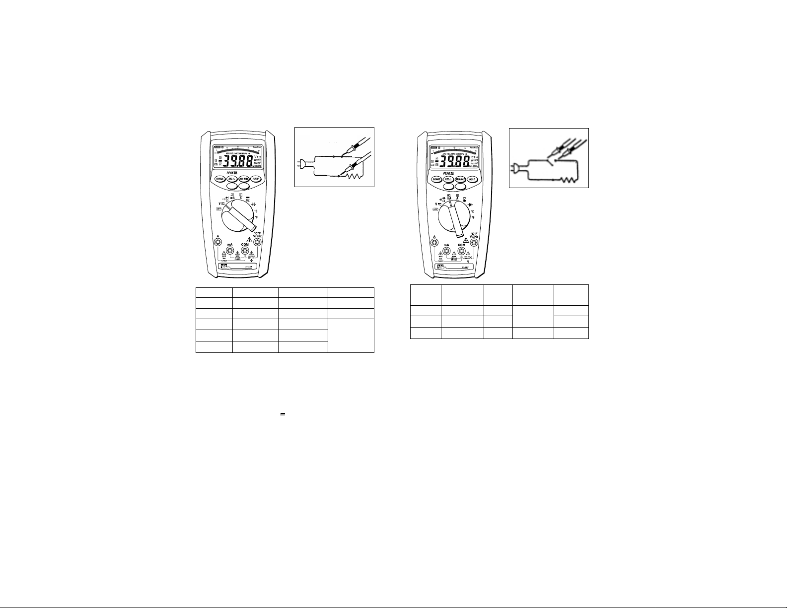
To Measure True RMS AC Current:
1. Plug the black test lead into the COM port and the red test
lead into the mA or A port.
2. Set the rotary switch to the mA or A position.
3. Push the blue button until AC is shown on the display.
4. Connect the meter in series with the load or circuit.
5. Measure AC Current.
˜
Circuit Connection:
Circuit Connection:
True RMS
True RMS
Page 5

Frequency/RPM
Range Resolution Sensitivity Accuracy
4.0KHz/40KRPM 1Hz/30RPM 100mV rms* Frequency:
40KHz/400KRPM 10Hz/300RPM 0.01% ±1 digit
400KHz/4MRPM 100Hz/3KRPM
4MHz/40MRPM 1KHz/30KRPM 250mV rms RPM:
40MHz/400MRPM 10KHz/300KRPM IV rms 0.01% ±10 digits
Overload Protection: 600V rms
*Less than 20Hz the sensitivity is 1.5V
To Measure Frequency:
1. Plug the black test lead into the COM port and the red test
lead into the °C°F VΩHz port.
2. Set the rotary switch to the HZ RPM position.
3. For RPM, Push the blue button until RPM is shown on
the display.
4. Connect the meter in parallel with the load or circuit.
5. Measure Frequency or RPM.
109
DC Current
Range Resolution Max Accuracy Voltage
Display Burden
40mA 10µA 40.00 ±(0.6% +2) 200mVmax
400mA 0.1mA 400.0 ±(0.7% +2) 2Vmax
10A 10mA 10.00 ±(1.0% +3) 2V max
Overload Protection: 1A (500V) fast blow fuse for mA input
16A (500V) fast blow fuse for A input
To Measure DC Current:
1. Plug the black test lead into the COM port and the red test
lead into the mA or A port.
2. Set the rotary switch to the mA or A position.
3. Push the blue button until
DC is shown on the display.
4. Connect the meter in series with the load or circuit.
5. Measure DC Current.
Circuit Connection:
Circuit Connection:
True RMS
True RMS
Page 6
1211
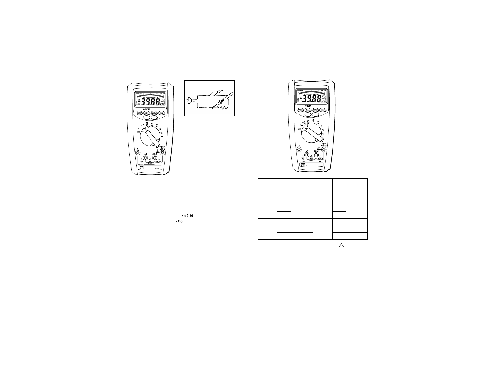
Resistance (Ohms)
Range Resolution MaxDisplay Accuracy
400Ω 0.1Ω 400.0 ±(0.7% +3)
4kΩ 1Ω 4.000 ±(0.4% +3)
40kΩ 10Ω 40.00
400kΩ 100Ω 400.0
4MΩ 1kΩ 4.000 ±(0.6%+3)
40MΩ 10kΩ 40.00 ±(1.5% +5)
Open Circuit Voltage: -1.3V approx.
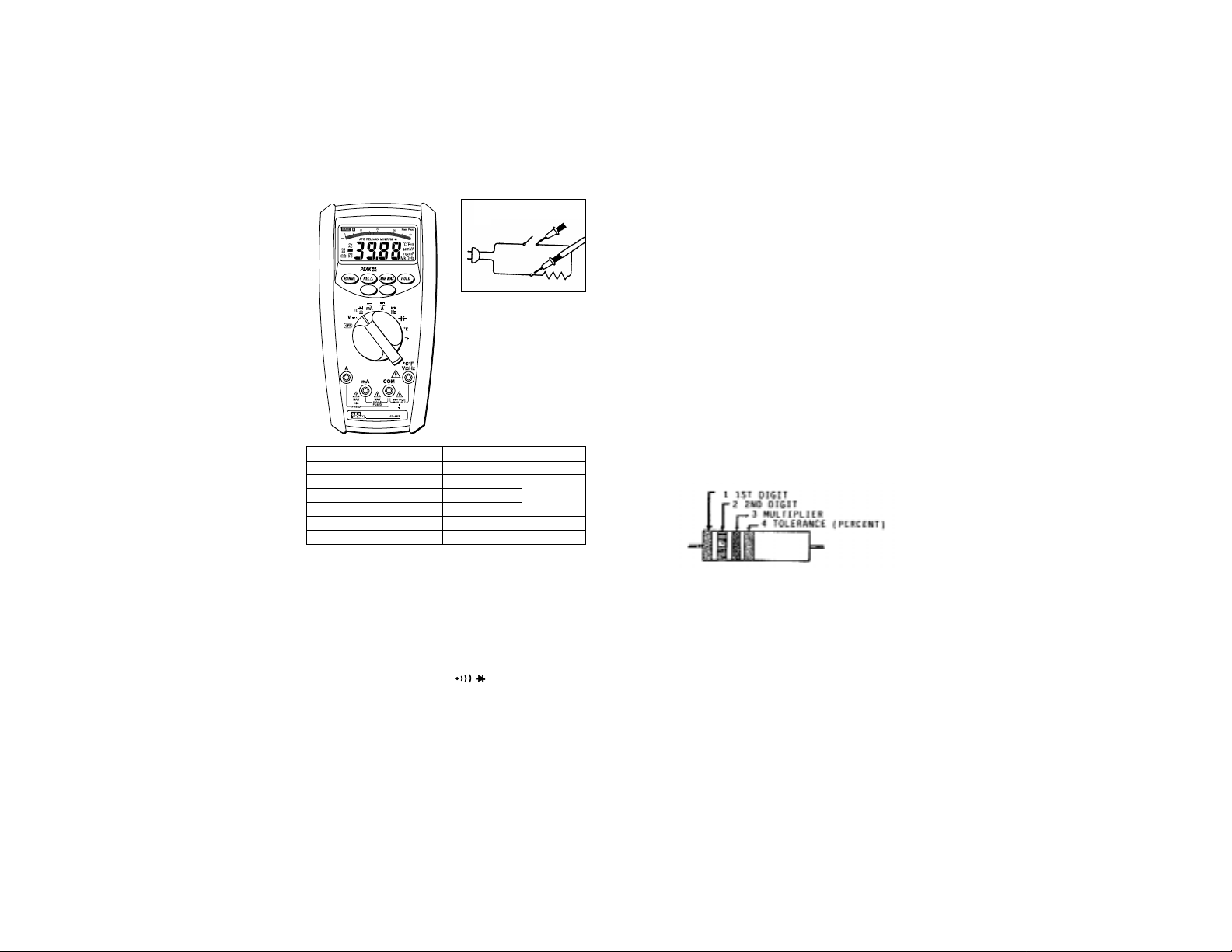
To Measure Resistance:
1. Turn the power off to the circuit or device that is to be
measured and discharge all capacitors before attempting a
measurement.
2. Plug the black test lead into the COM port and the red test
lead into the °C°F VΩHz port.
3. Set the rotary switch to the Ω position.
4. For correct reading, ensure that the device being tested
contains no voltage.
5. Press the range button to select the proper range of the
meter.
6. Measure resistance.
Circuit Connection:
Range Guide for Ohms (Ω):
400 = Meter indicates actual resistance
4k = Multiply meter display reading by 1,000 to
acquire actual resistance.
40k = Multiply meter display reading by 1,000 to
acquire actual resistance.
400k = Multiply meter display reading by 1,000 to
acquire actual resistance.
4M = Multiply meter display reading by
1,000,000 to acquire actual resistance
400M= Multiply meter display reading by
1,000,000 to acquire actual resistance.
The meter displays total resistance through all possible paths between the probe-tips. These multiple
paths may result in measurements that do not correspond to the ohm value indicated by the resistor
color code.
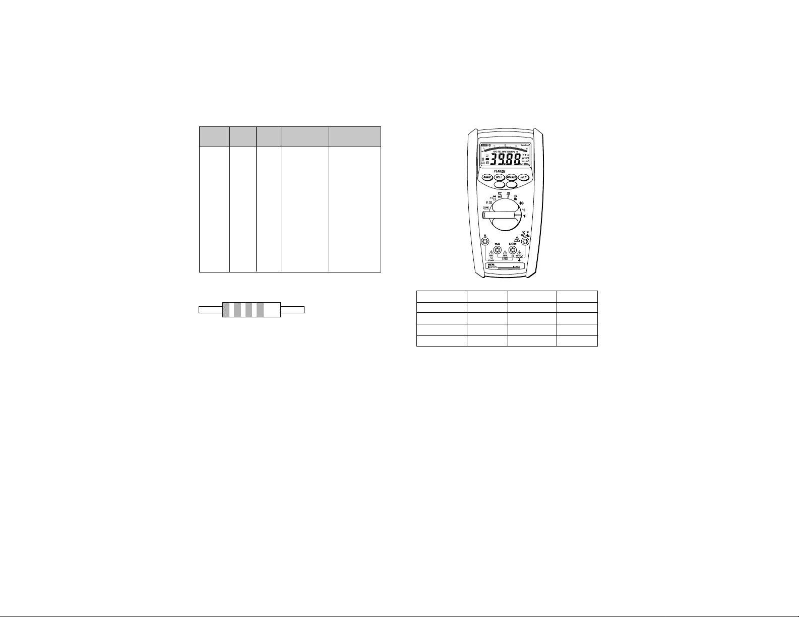
Determining Resistor Values:
To determine the value of a resistor, use the color bands on the
resistor and the table on the following page.
True RMS
Page 7
1413
Resistor Color Code Table
1st 2nd Tolerance
Color Digit Digit Multiplier (Percentage)
Black 0 0 1
Brown 1 1 10
Red 2 2 100
Orange 3 3 1,000
Yellow 4 4 10,000
Green 5 5 100,000
Blue 6 6 1,000,000
Violet 7 7 10,000,000
Gray 8 8 100,000,000
White 9 9 1,000,000,000
Gold +/- 5%
Silver +/- 10%
No Color +/- 20%
Example:
1st color band is blue so the first digit is a 6
2nd color band is red so the second digit is a 2
3rd color band is yellow so multiply 62 x 10,000
4th color band is gold so the tolerance is ±5%
Your Resistor value is 620,000 Ohms (620kΩ) with a tolerance
of ±5%.
Blue
Red
Yellow
Gold
Temperature
Temperature Accuracy Temperature Accuracy
-4°F ~ 32°F ±(2% + 8°F) -20°C ~ 0°C ±(2% + 4°C)
33°F ~ 212°F ±(1% + 6°F) 1°C ~ 100°C ±(1% + 3°C)
213°F ~ 932°F ±(2% + 6°F) 101°C ~ 500°C ±(2% + 3°C)
933°F ~ 1472°F ±(3% + 4°F) 501°C ~ 800°C ±(3% + 2°C)
Overload Protection: 600V rms
To Measure Temperature:
1. Connect the thermocouple to the temperature adapter with
the “+” on the thermocouple lining up with the “+” on the
adapter and the “K” on the thermocouple lining up with the
“-” on the adapter.
2. Plug the temperature adapter into the 61-492 with the “+”
inserted into the port and the “-” inserted into the COM port.
3. Set the rotary switch to either the °F or °C position.
4. Measure temperature.
True RMS
Page 8

16
15
Diode Testing
Function Resolution Accuracy Max.Test Max.Open
Current Circuit
Voltage
1mV +(1.5% +5)* 1.5mA 3V
* For 0.4V to 0.8V.
Overload Protection: 600V rms max
Diode Check:
To ensure a proper functioning diode, the meter will develop a
voltage across the component from a test current. The diode
test function allows measurements of forward voltage drops
across diode and transistor junctions.
1. Turn off power to the device or circuit that is being tested
and discharge all capacitors.
2. Plug the black test lead into the COM port and the red test
lead into the °C°F VΩHz port.
3. Set the rotary switch to the Ω position.
4. Press the blue button until is shown on the display
5. Connect the test leads to the diode. Normally the forward
voltage drop of a good silicone diode is shown between
400V and 90V. If the diode under test is defective, “000”
(short circuit) or “OL” (non-conductive) is displayed.
Circuit Connection:
Capacitance
Range Resolution Accuracy
4nF 1pF ±(3% + 10 digits)
40nF 10pF
400nF 100pF ±(2% + 6 digits)
4µF 1nF
40µF 10nF
400µF 100nF
4mF 1µF ±(5% + 20 digits)
40mF 10µF
Overload Protection: 600V rms
To Measure Capacitance:
1. Plug the black test lead into the COM port and the red test
lead into the °C°F VΩHz port.
2. Set the rotary switch to the position.
3. Connect the test leads to the circuit to be measured.
4. Measure capacitance.
True RMS
True RMS
Page 9
1817
Continuity Check
To Verify Continuity:
A continuity test ensures that all circuit connections are intact.
1. Plug the black test lead into the COM port and the red test
lead into the °C°F VΩHz port.
2. Set the rotary switch to the Ω position.
3. Press the blue button until is shown in the display.
4. Connect the test leads to the circuit to be measured. The
buzzer will sound if the resistance of the circuit measured is
lower than 30Ω.
Circuit Connection:
Peak Hold Measurements
Function Range Accuracy Function Range Accuracy
DC Voltage 400mV Unspecified AC Voltage 400mV Unspecified
4V ±(1.5% +300) 4V ±(1.5% +300)
40V ±(1.5% +60) 40V ±(1.5% +60)
400V 400V
1000V 750V
DC Current 40mA ±(3% +60) AC Current 40mA ±(3% +60)
400mA 400mA
10A ±(1.5% +60) 10A ±(1.5% +60)
In current and voltage measurements, the REL button
performs a peak hold function. The peak hold mode must be
calibrated prior to use. To calibrate the peak hold, press the key
until the meter displays “CAL”. Short the test leads to calibrate.
True RMS
True RMS
Page 10

19
20
Accessories
For AC Current Clamp (61-450):
1. Plug the black test lead into the COM port and the red test
lead into the VΩHz port.
2. Remove the probe tips from the end of the leads.
3. Attach the leads to the current clamp. (polarity will not effect
reading)
4. Set the rotary switch to the V position.
5. Push the blue button until
AC is shown on the display.
6. Snap the jaw of the current clamp around one of the current
carrying conductors.
True RMS
˜
General Specifications
LCD Display: 4000 count maximum reading
Bar Graph Display: 82 segment analog bar graph
Polarity Indication: Automatic, negative indicated,
positive implied
Overrange Indication: “OL” or “-OL”
Low Battery Indication: “ ” when the battery voltage
drops below operating
voltage
Size (WxHxD): 88mm x 180mm x 33.5mm
(without holster)
94mm x 188mm x 40mm
(with holster)
Sampling: 2 times/sec LCD Display,
12 times/sec bar graph
Auto Power Off: Approx. 30 min.
Operating Temperature: 0°C ~ 30°C (<80% RH),
30°C ~ 40°C (<75% RH),
40°C ~ 50°C (<45% RH)
Storage Temperature: -20°C ~ 60°C (0~80% RH)
when battery removed from meter
Temperature Coefficient: 0.15 x (specified accuracy) /
°C, <18°C or >28°C
Power Requirements: 9V NEDA 1604, 1EC bf 22,
J1S 006P
Battery Life: 300 hours (alkaline )
Installation Category: IEC 1010, 1000V Cat. II,
600V Cat III
Environmental Conditions
Indoor Use
Maximum Altitude: 2000 Meter
Installation Category: IEC 1010, 1000V Cat II,
600V Cat. III
Pollution Degree: 2
C
Page 11

21
Maintenance
Battery Installation or Replacement:
The #61-480 is powered by one 9V battery.
1. Remove the test leads from the front terminals and turn the
meter off.
2. Remove the screw from the battery cover and lift to remove.
3. Replace battery.
4. Make sure the battery box leads do not become pinched
between the case and battery cover before replacing the
battery cover and screw.
Fuse Replacement
1. Remove the test leads from the front terminals and turn the
meter off.
2. Remove the screw from the battery cover and lift to remove.
3. Remove the screws from the bottom case and the inside of
the battery cover and lift the case bottom until it unsnaps
from the case top.
4. Remove the defective fuse by gently prying one end of the
fuse loose and sliding the fuse out of the fuse holder.
5. Install a new fuse of the same size and rating. Make sure it
is centered in the fuse holder.
6. Make sure the battery box leads do not become pinched
between the case and battery cover before replacing the
bottom case and battery cover.
22
Warning
To avoid electrical shock, remove test lead before opening the
cover. Repairs or servicing not covered in this manual should
only be performed by qualified personnel.
Page 12

IDEAL INDUSTRIES, INC.
Sycamore, IL 60178, U.S.A.
800-304-3578 Customer Assistance
www.testersandmeters.com
ND 2366-1 Made in Taiwan
Lifetime Limited Warranty
This meter is warranted to the original purchaser against
defects in material or workmanship for the lifetime of the meter.
During this warranty period, IDEAL INDUSTRIES, INC. will, at
its option, replace or repair the defective unit, subject to
verification of the defect or malfunction.
This warranty does not apply to defects resulting from abuse,
neglect, accident, unauthorized repair, alteration, or
unreasonable use of the instrument.
Any implied warranties arising out of the sale of an IDEAL
product, including but not limited to implied warranties of
merchantability and fitness for a particular purpose, are limited
to the above. The manufacturer shall not be liable for loss of
use of the instrument or other incidental or consequential
damages, expenses, or economic loss, or for any claim or
claims for such damage, expenses or economic loss.
State laws vary, so the above limitations or exclusions may not
apply to you. This warranty gives you specific legal rights, and
you may also have other rights which vary from state to state.
 Loading...