

Page 1
2
#61-805
800 Series
Power Analyzer Energy & Harmonics Program
1
2
5
3
4
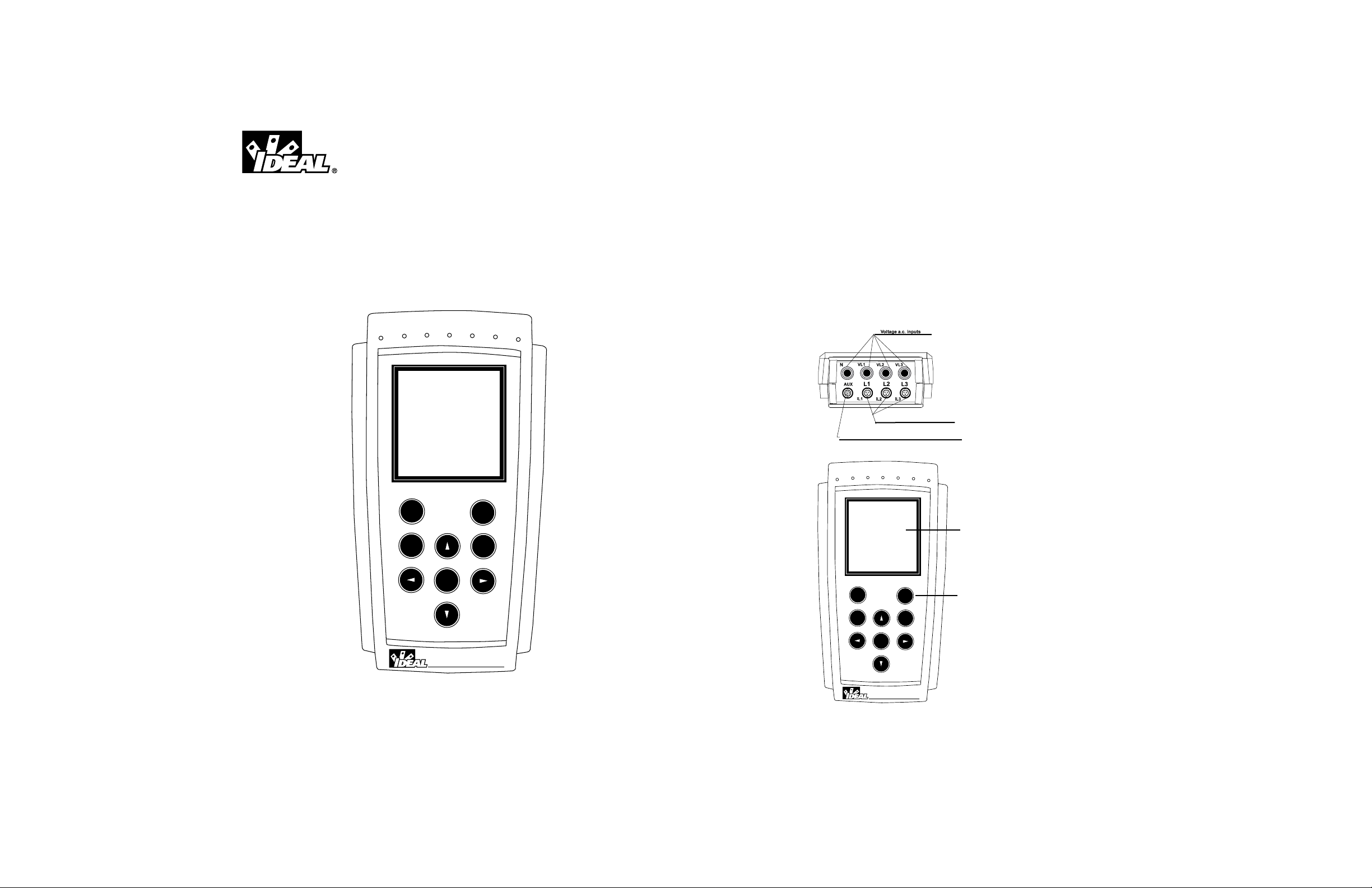
1. LCD Display
2. Keypad
3. Voltage Input Terminals
4. Amp Clamp Input Terminals
WARNING!
1. DO NOT UNDER ANY CIRCUMSTANCES EXCEED THESE RATINGS:
- 500VAC phase-neutral
- 866VAC phase-phase
2. To avoid electrical shock hazards and/or damage to the meter:
- Do not exceed the voltage ratings for the meter. - Use caution when measuring voltage.
- Do not use during electrical storms. Electrical storms may result in high voltage. High-energy transients can
damage meter and present a dangerous shock hazard.
3. Ensure meter is in proper working order before using. Visually inspect meter for damage.
4. Never ground yourself when taking electrical measurements. Do not touch exposed metal pipes, outlets, fixtures etc.
Keep your body isolated from ground by using dry clothing, rubber shoes, mats, or any other approved insulating
material. Keep your fingers behind the finger guards on the probes. Work with others.
5. Before breaking a circuit for testing, turn off the power to the circuit. When disconnecting from a circuit, disconnect
the hot lead first, then the common lead.
6. Disconnect the meter from the circuit before turning off any inductor, including motors, transformers, and solenoids.
Power Analyzer
ON
ESC
OFF
ENTER
SET
61-805
Power Analyzer
ON
ESC
OFF
ENTER
SET
61-805
Page 2
3 4
LCD Display
160 x 160 pixel display that permits the visualization of measurement values, graphs and waveforms depending on the
software program selected.
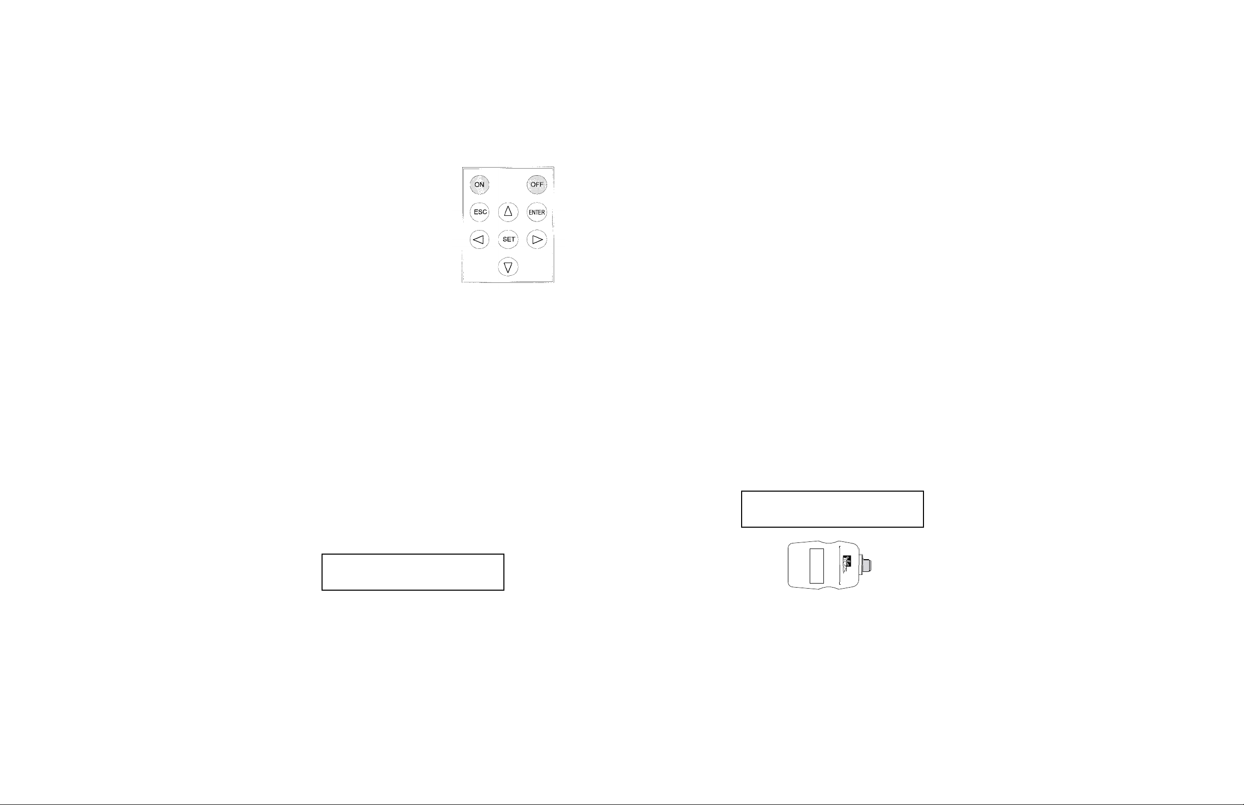
Keypad
• ON and OFF buttons to turn the 61-805 on and off.
• ▲, ,▼, and buttons to select among options and
move through the menu of the 61-805.
• SET button to access setting options.
• ENTER button to validate a setting option or to program
software parameters.
• ESC button to select different displays during operation or
to exit menu settings.
Voltage Input Terminals
• Always use the test leads supplied with the 61-805.
• The maximum phase to neutral voltage is 500VAC.
• The maximum phase to phase voltage is 866VAC.
Amp Clamp Input Terminals
• The 61-805 comes standard with three 1000AAC Clamp Adapters.
• Clamp adapters with other current ratings are available, and can be ordered though your local IDEAL distributor.
• The primar y and secondar y transformer ratings are set-up within the menu of the power analyzer. (See page 15.)
Auxiliary Input
• This connection is used to power the meter, recharge the batter or download data by connecting to the power supply/serial adapter or use to download new software by connecting to a software loader.
Powering up the 61-805
1. The battery of the Power Analyzer must be charged, or plugged into the power supply prior to start-up. The power
supply needs to be plugged into a 120VAC supply at a grounded outlet.
2. Press the ON button on the keypad. The power analyzer introduction screen should appear on the LCD display.
3. After a few seconds the program selection screen appears to choose among the software analysis programs loaded
onto the analyzer. Up to four software programs can be loaded onto the power analyzer.
4. Use the arrow buttons to navigate through the selections
5. Press enter to select the appropriate software program.
6. If a selection is not made within a few seconds, the analyzer will automatically begin the first software program.
7. All software programs have different set-ups and operating parameters. Refer to the manual for the selected software for instructions.
▲
▲
Recharging the Battery
The battery life of the 61-805 is 4 to 10 hours, depending on the measurement settings selected within the menu. For
long term analysis, it is recommended to plug into the power supply/serial adapter. The 61-805 is equipped with an
intelligent energy charging system that continuously checks the state of the battery. The charging process stops when
the battery is at its maximum charge level, increasing the life of the battery.
1. Plug the power supply in at a grounded outlet.
2. Connect the power supply to the power analyzer.
3. Turn the power analyzer on by pressing the ON button.
4. If the battery is exhausted, the charging process should last at least 3 hours with no interruption.
5. A charging period of 16 hours is advisable in order to completely charge the battery.
6. The 61-805 displays a battery charge indicator on the LCD.
Auto Display Shutoff
The 61-805 has an auto display shutoff to save power. If no key is pressed for at least 5 minutes, the display automatically shuts off. The analyzer continues to record data, but nothing appears on display. The display will be automatically on when any key is pressed.
Loading a New Program
IDEAL offers a wide variety of software programs to troubleshoot power quality issues such as harmonics and electrical
disturbances. Up to four software programs can be stored and run on a single power analyzer.
1. Before loading new software, check to make sure the 61-805 battery is charged. Loading programs cannot be done
when the power supplier is connected to the power analyzer.
2. Turn the meter off.
3. Connect the cartridge to the auxiliary input of the meter.
4. Turn the meter on.
5. Select LOAD PROGRAM with the arrow keys and press the ENTER button to confirm this operation.
6. Select the position to save the program into.
7. The 61-805 will perform a test to ensure that the cartridge has been properly connected.
8. If an un-serialized software cartridge is detected, the program will be loaded. The power analyzer will update the
software program cartridge, matching it to the serial number of the 61-805. Each software program cartridge can
be used more than once, but only with the matching power analyzer.
9. Once the loading is completed, turn off the power analyzer.
10. If no cartridge was found or a loading mistake occurred, turn off the power, and restart the above loading steps.
Note: The 61-805 comes standard with the Energy
Program. The set-up and operation instructions for this
program are located in this manual.
Note: A cartridge will be only valid for the analyzer which
the program was for the first time loaded into. Note on the
cartridge the serial number of its related 61-805.
Serial #
61-805 Serial #
Page 3
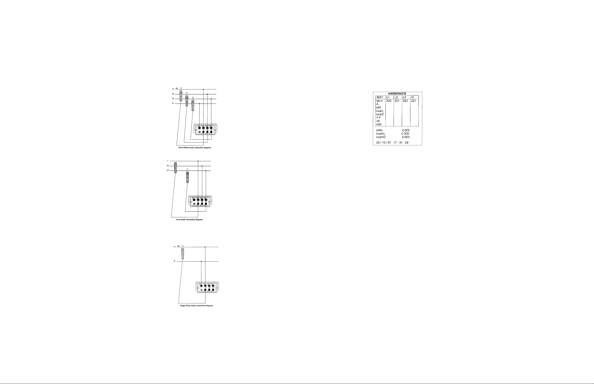
Connecting to your Electrical System
The 61-805 power analyzer can be configured for three types of electrical systems: three-phase systems, aron systems
(rotary input), and single-phase systems. Enclosed are connection diagrams for each of these electrical systems.
Three-Phase Mode Connection Diagram
Aron Mode Connection Diagram
Single-Phase Mode Connection Diagram
5
Operating the Power Analyzer
All measured values, as well as maximum and minimum, can be read on a 160 x 160 pixel, liquid, crystal display. Data
is viewed on a variety of screens. Pressing the [ESC] key will change the screen view on the power analyzer.
Base Screen
The base screen appears when the power analyzer first enters the harmonic program.
INST, MAX or MIN
An indication of the type of data being displayed is shown at the upper right corner: INST (Instantaneous), MAX
(Maximum) or MIN (Minimum).
Maximum and minimum values displayed correspond to the maximum and minimum values obtained from the instantaneous values.
Vp-n (voltage phase to neutral)
Readout of the instantaneous RMS value measured at each phase (L1, L2 & L3) and the average value of the instantaneous values of the three phases (III).
A (current)
Readout of the instantaneous RMS value measured at each phase (L1, L2 & L3) and the average value of the instantaneous values of the three phases (III).
kW (active power)
The active power is calculated from instantaneous voltage and current data. The readout gives the instantaneous values
of the active power of each phase and also the three phase total instantaneous active power, which is the addition of each
phase value.
kvarL(inductive reactive power)
The inductive reactive power is calculated from instantaneous voltage and current data. The readout gives the instantaneous values of the inductive reactive power of each phase and also the three phase total instantaneous inductive reactive power, which is the addition of each phase value.
KvarC (capacitive reactive power)
The capacitive reactive power is calculated from instantaneous voltage and current data. The readout gives the instantaneous values of the capacitive reactive power of each phase and also the three phase total instantaneous capacitive reactive power, which is the addition of each phase value.
P.F. (power factor)
Readout of the power factor of each phase and the three phase average value.
6
Page 4

Hz (frequency)
Readout of the instantaneous value of the frequency.
KVA (apparent power)
Readout of the three phase total instantaneous apparent power, which is the addition of each phase value.
KWh, kvarhL, kvarhC (energy measurements)
Readout of active, inductive reactive, and capacitive energy counters from the moment that the energy counters were reset
to zero (see section Error! Reference source not found.)
Date and Time
Readout of present time and date.
Expanded View Screen
In this view, three parameters of your choice can be displayed in a larger type for easier viewing.
Only three instantaneous readings may be viewed at once. The parameters can be selected in the display section of the
programming menu.
Bar Graph Screen
This screen gives a graphic representation of the three phases (L1, L2 & L3) of the selected parameter.
The parameter and the bar graph scale can be selected in the display section of the programming menu.
8
Oscilloscope Screen
This screen displays the voltage and current wave forms of each phase (L1, L2 & L3).
Both the voltage and the current waveforms of the captured cycle are shown on the screen together with their respective
effective values.
• The [ ] & [ ] keys move along the ordinate axis, to display the voltage and current values.
• The [ ] & [ ] keys move up and down the left menu bar to acquire a new wave form, or zoom in on an individual
waveform.
-Select “Adq” and press enter to acquire a new wave form.
-Select “L1”, “L2” or “L3” for either the voltage or current to zoom in on an individual wave form.
Zoom View of the Wave Form
This view shows the individual wave form in detail.
• The indicates the phase of the voltage or current wave form that is being displayed in the zoom view.
• The [ ] & [ ] keys move along the ordinate axis, to display the voltage and current values.
• The [ ] & [ ] keys move up and down the left menu bar to acquire a new wave form, or zoom in on an individual
waveform.
-Select Adq and press enter to acquire a new wave form.
-Select L1, L2 or L3 for either the voltage or current to zoom in on an individual wave form.
7
▲
▲
▲
▲
▲
▲
▲
▲
▲
Page 5

Harmonic Factorization Screen
In this screen, the harmonic factorization of the signal is displayed in a bar graph.
• The indicates the phase of the voltage or current wave form that is being displayed in the zoom view.
• The [ ] & [ ] keys move along the ordinate axis, to display the individual harmonic and distortion level in the table.
• The [ ] & [ ] keys move up and down the left menu bar to acquire a new wave form, or zoom in on an individual
waveform.
-Select “Adq” and press enter to acquire a new wave form.
-Selecting ODD or EVEN switches between even or odd
harmonics.
-Select L1, L2 or L3 for voltage or current to change the selected phase for harmonic factorization.
Setup Screen
This screen displays the selected setup parameters for the power analyzer.
The screen on the left is the one shown on the analyzer’s display. The screen on the right explains the meaning of each
term. “A5I Type” will only be shown when a harmonic type file (A5I) is programmed to determine which harmonic file
is selected (“Harm. 30” or “Harm. 50”)
HARMONICS HARMONICS
25/10/97 7:31:29 Present date
Warning Messages
Some warning messages can appear at the visualization screens. These messages inform about the 61-805 performance:
STOP: The analyzer is not recording data.
TRIG?: Trigger conditions are not met. No data is being recorded.
M. Full: Memory is full.
M.Error: There is an error in the memory. The memory must be formatted. Analyzer’s battery status. When only
one bar is displayed the battery should be recharged since the analyzer may be off at any moment.
10
WARNING MAX 500 V: The maximum allowable phase to neutral voltage of 500 V has been exceeded during the mea-
suring process. When measuring phase to phase voltages the limit is set at 866 V.
Programming the 61-805
To access the 61-805 setup options, press the key [SET]. The analyzer prompts for a password, consisting of a key
sequence. The user has 15 seconds to enter the correct password, or the analyzer returns to run mode.
Once this password is entered, the analyzer will permit the user to modify any Setup parameters.
All programs have an independent setup. Check the setup to ensure a proper operation, since any modification will only
affect the active operation program.
The initial programming menu allows access to the power analyzers setup, display, run, files and clear menus.
• Select one option with keys [ ] & [ ].
• To access any menu option use [ ] or [ENTER].
• To close the menu press [ ] or [ESC]. If a any setup parameter was changed, a confirmation is requested before
closing.
Setup Menu
The power analyzer can be configured to customize the data collection.
• Press [ ] or [ ] keys to select the sub menu within the setup menu.
• Press [ENTER] to enter the sub menu or [ESC] to exit without modification.
▲
▲
▲
▲
▲
SETUP
Type of measuring circuit
V.T. ratio C.T. ratio
Name and type of file
Recording period Type A51
Trigger: parameter
Max. Value Min. Value
Trigger: date/time On
Trigger: date/time Off
Communication parameters
SETUP
Measure: Triphasic
1/1V 5A
File: Std-prog. A5M
00:15:00 Harm. 50
Trigger: Auto
00
00/00/92 00:00:00
00/00/92 00:00:00
Com: 9600 / No / 8 / 1
9
▲
▲
▲
▲
▲
▲
Page 6

Trigger
The power analyzer can be set up so that values are saved in memory only when certain conditions are met. The two
types of trigger conditions are:
Level
• Sets the analyzer up to record data when a selected parameter falls outside a specified range.
• Select the parameter to trigger measurement. (Vp-p, Vp-n, A, kW, kvarL, kvarC, PF, Hz, kVA, Auto (None)).
• Set the maximum value of the range. If the measurement rises above this value, data collection will begin.
• Set the minimum value of the range. If the measurement falls below this value, data collection will begin.
• To void this trigger condition, set the parameter to Auto.
Time
• Programs a start and stop time for the power analyzer.
day/month/year hour:minute:second
day/month/year hour:minute:second
• To void the time trigger, all values must be zero.
If both the level and time triggers are set, both conditions have to be met for data to be saved. If they are met, the data
within the entire period will be stored.
Name
• Set the file name.
• Maximum of 8 characters (no extension)
• A keyboard will appear on the screen to enter a file name.
• Select each character with the arrow keys, [ ], [ ], [ ] or
[ ] and press [SET] to validate each character.
• Select “ “ on the keyboard + [SET] to delete a
character.
• Press [ENTER] to validate the file name or [ESC] to exit with no modification.
• If the file name and extension already exist in memor y, a conformation is requested before overwriting.
Measure Submenu
Within the measure submenu, the analyzer can be set up for the configuration and voltage and current levels of the
electrical system under test.
• Press [ ] or [ ] keys to select the parameters within the measure submenu.
• Press [ENTER] to select or [ESC] to exit without modification.
Circuit
Available circuit types are Three phase systems, or ARON systems (rotary input). For single-phase systems, select a
three-phase configuration, connect the clamp adapter to L1 and the voltage leads to the N and VL1.
TR. REL
Select TR.REL to adjust the transformer ratios.
• If the voltage is measured directly, set the primary voltage and secondary voltage to 1.
• The current transformers included with the 61-805 have a primar y current of 1000A and a secondar y voltage of 2V.
• Always use IDEAL clamp adapters specified for the power analyzer.
• Never connect a direct current measurement to the 61-805.
Record Submenu
The parameters of the data collection are accessed in the record submenu.
Press [ ] or [ ] keys to select the parameters within the record submenu.
Press [ENTER] to select or [ESC] to exit without modification.
Period
• Each data point stored within the 61-805 consists of the average values measured during the period.
• The recording period can be set to ever y second 1 second to ever y four hours for .A5M and .A5T file extensions.
• For harmonic file extensions, .A5I, the recording period can be set from ever y five seconds to ever y 4 hours.
11 12
▲
▲
▲
▲
RECORD
PERIOD
TRIGGER
NAME
TYPE
PARAM
hh:mm:ss (1 s to 4 h or 5 s to 4 h) acc. file type
Level, time
File name (8 characters)
File type: standard or special
Special file parameters
TIME .ON
00/00/00 00:00:00
TIME .OFF
00/00/00 00:00:00
NAME
STD-PROG
▲
▲
➔
▲
▲
Page 7

14
Comm Submenu
Within the Comm submenu, the communications parameters for the RS232 connection can be configured.
Baud Parity Length Stop Bits
• Move through the parameters with the left and right arrow keys [ ] or [ ].
• With the up and down keys, [ ] and [ ] change the value of the parameter.
• Press [ENTER] to validate the changes or [ESC] to exit with no modification.
Clock Submenu
Within the clock submenu, the power analyzers internal clock can be changed.
day/month/year hour:minute:second
• Move through the parameters with the left and right arrow keys [ ] or [ ].
• With the up and down keys, [ ] and [ ] change the value of the parameter.
• Press [ENTER] to validate the changes or [ESC] to exit with no modification.
Recall Submenu
Within the recall submenu, the power analyzers setup can be reset to factory configured parameters.
With the arrow keys, [ ] & [ ], select yes or no, and then press [ENTER].
A confirmation is requested before changes are made.
The “Standard” operation parameters are:
- C.T. Ratio (SET + A) : 5
- V.T. Ratio (SET + V) : 1 / 1
- TRI/ ARON : Three phase (TRIPH).
- Period (SET + PERIOD) : 15 minutes
- TRIGGERS (Time and parameter) : All set to zero
- File name (FILE Name) : STD-PROG
- FILE type : .A5M
- Communication parameters : 9600,No,8,1
- RUN : RUN
Display Menu
Within the display menu, the power analyzer’s display screen can be configured for specific measurement values.
13
Type
• Select the file type wanted for data recording with the arrow keys, [ ] or [ ].
• Choose from the following file types: Standard, Custom, Harm30 or Harm50.
• A5M Standard file (preset parameters).
• A5T Custom file (user-selected parameters).
• A5I Harmonic file (preset parameters + wave forms). Harm30 captures factorization to the 30th harmonic and Harm50
captures factorization to the 50th harmonic.
Length of data saving records is different as per each file type. Memory autonomy for a 15 min recording period is listed below:
File Type Extension Record Length 61-805 1Mb
Standard A5M 200 bytes 52 days
Custom A5T 4*no.par+10 bytes days
Harm. 30 A5I 1000 bytes 10.4 days
Harm. 50 A5I 1800 bytes 5.9 days
If the file name and extension already exist in memory, a conformation is requested before overwriting.
Param
• Set the parameters to be saved.
• A table will appear containing the full listing of available parameters.
• Use the arrow keys, [ ], [ ], [ ] or [ ], to navigate through the table.
• Press [SET] to change the state of the parameter from saved or not saved.
• Parameters to be saved are on a black background, and the ones not saved are on a white background.
• By selecting INST (Instantaneous values) and pressing [SET], you can toggle between the instantaneous values,
maximum values and minimum values.
• Press [ENTER] to validate the choice or [ESC] to exit with no modification.
A5M A5I
Parameters L1 L2 L3 III L1 L2 L3 III
Phase-Neutral Voltage x x x x x x x x
Max Phase-Neutral Voltage x x x x x x
Min Phase-Neutral Voltage x x x x x x
Current x x x x x x x x
Max Current x x x x x x
Min Current x x x x x x
Active Power x x x x x x x x
Inductive Power x x x x x x x x
Capacitive Power x x x x x x x x
Power Factor x x x x x x x x
Active Energy x x
Inductive Energy x x
Capacitive Energy x x
Frequency x x
Wave form V x x x
Wave form I x x x
▲
▲
1000000-192
(4*n° var+10)*96
▲
▲
▲
▲
COMM
9600 NO 8 1
TIME .ON
00/00/00 00:00:00
▲
▲
▲
▲
▲
▲
▲
▲
▲
▲
DISPLAY
OPTIONS
CONTRAST
DISPLAY MENU
☞
Page 8

16
Files Menu
Up to 1 Meg of data can be stored in the memory of the
61-805. Once full, the power analyzer will cease recording new data, and the display shows: “MEMORY FULL.” Old
data will not be overwritten.
DIR (Directory)
This sub menu selection displays a directory of all files saved in memory.
61-805 - DIR
STD-PROG. 61-805 xxxxx bytes File name/File size
dd / mm / yy hh : mm : ss Day / Time
TEST1. A5T xxxxx bytes
dd / mm / yy hh : mm : ss
STD-PROG. A5T xxxxx bytes
dd / mm / yy hh : mm : ss
...... / .............
Free bytes: xxxxxxxxxx Number of free bytes in memory
• The [ ] or [ ] keys scroll up and down through the files in case that all files stored by the power analyzer cannot
be shown in only one screen.
• Press [ENTER] or [ESC] to exit.
Delete
From this submenu, any file can be deleted from the internal memory.
61-805 – DELETE
STD-PROG. A5M xxxxx bytes File name / File size
TEST1. A5T xxxxx bytes
STD-PROG. A5T xxxxx bytes
...... ............
• With the arrow keys, [ ] & [ ], select the file to be deleted.
• Press [ENTER] to confirm selected file erasing. A confirmation is required.
• Press [ESC] to exit without deleting a file.
Format
This submenu formats the internal memory of the 61-805.
61-805 – FORMAT
15
Options Submenu
Within the options submenu, you can set up the parameters to be visualized on the screens, and the display
contrast.
Measure
• Set up the parameters to be visualized on display in the bar graph and expanded view screen
Bar Graph
• Select the measurement parameter to be viewed on the bar graph.
• Scroll through the options with the up and down keys, [ ] or [ ].
• Press [ENTER] to validate selection or [ESC] to exit with no modification.
• Set the scale by selecting the zero scale and full scale measurement values
Expand
To choose three instantaneous parameters to be bigger-size displayed for a clearer reading.
• Select three measurement parameters to be viewed on the expanded view screen.
• Scroll through the table of options with the up and down keys, [ ] or [ ].
• Press [ENTER] to validate selection or [ESC] to exit with no modification.
Volt
This submenu permits the user to select the voltage readout in the main visualization screen. It can correspond to the
voltage between phases (Vp-p) or between phase and neutral (Vp-n).
• Select with the up and down arrow keys [ ] or [ ].
• Press [ENTER] to validate the choice or [ESC] to exit with no modification.
Options Submenu
Within this submenu, the contrast of the 61-805 display can be modified.
• Press the [ ] to intensify the display contrast and [ ] to lower the screen contrast.
LOW HIGH %
Run Menu
The data collection and logging action of the power analyzer can be enabled or disabled from the run menu.
• Press [ ] or [ ] keys to RUN or STOP data collection.
• Press [ENTER] to validate or [ESC] to exit with no modification.
OPTIONS
MEASURE
VOLT
Bar graphs, expanded param (3 parameters)
Vphase-phase or Vphase-neutral
(Vp-p or Vp-n)
▲
▲
▲
▲
▲
▲
▲
▲
CONTRAST
➔
➔
RUN
Run / Stop
▲
▲
☞
☞
▲
▲
☞
▲
▲
Page 9

18
Commands
COMMAND CONCEPT QUESTION ANSWER
VER Read 61-805 version $00 VER ch $00 4 digits + ch
DIN Number of files $00 DIN ch $00 5 digits + ch
in memory
DIR Directory of one $00 DIR + 5 $00 + 12 file name
file in memory number of the ext + 7 num.
file to be Bytes + 17 date of
displayed + ch file creation + ch
SZC Ask for a file $00 SZC + 12 $00 initial date + end date +ch
file name. The AR5 starts to communicate
ext + ch under Zmodem protocol.
$00 ERR00 + ch
61-805 in Setup menu.
$00 ERR if file does not exist
SZP Ask for a part $00 SZP $00 ACK + ch.
of a file + 12 file name The 61-805 starts to communicate
.ext + initial under Zmodem protocol.
date + end
date ch $00 ERR00 + ch.
AR5 in Setup menu.
$00 ERR + ch. if file does not
exist or initial date > end date
DIF Consult a file $00 DIF 12 $00 12 file name.ext + initial
content file name.ext date + end date + 6 number
+ ch bytes ASCII + ch
Note: The date format is “DD/MM/AA hh:mm:ss” with a 17 bytes length.
Communication Wiring
The connection of the PC to the 61-805 must be done through the power supplier set, which needs to be connected to
power. Perform the connection using the two wires factory-delivered with the 61-805.
One cable links the 61-805 to the power supplier, and the other cable is a standard RS232 connector.
When starting communication tasks take into account:
• Communication parameters of the 61-805 and the PC must fully coincide.
• Connections must go through the power supply.
• The 61-805 cannot be into the setup menu.
Communications Software
The 61-805 power analyzer comes complete with a powerful software package, Power Vision, to assist in analyzing the
data captured by the power analyzer. See the Power Vision instruction sheet for complete details on the operation of
this software.
A confirmation is required prior to formatting the internal memory. Formatting the memory of the power ana-
lyzer will delete all stored data.
Note: Do not turn the 61-805 off during the memory format process, the display will show an error message and the
process should be redone.
Clear Menu
The clear menu resets saved parameters within the power analyzer.
Energy
The power analyzer has several energy counters, which keep their values even after the analyzer is turned off. These
values can be reset by selecting the energy submenu and pressing enter.
MAX/MIN:
The maximum and minimum values are stored by the 61-805, even after the analyzer is turned off. These values can be
reset by selecting the MAX/MIN submenu and pressing enter.
Communications Protocal
Demand format
The demand format is: $00CCCAA.... ch [LF]
(example = $00RVI75 )
The answer format is: $00AA.... ch [LF]
$ Any message starts with this symbol (ASCII-36)
PP The identification code for the portable AR5 is always 00
CCC COMMAND
AA ARGUMENT (decimal-ASCII)
Ch CHECK-SUM: Check-sum of all the elements forming the message. It is calculated
with the decimal addition of all the previous bytes in ASCII and translating the result
to hexadecimal. Two digits are taken.
example = $00RVI —> 36 + 48 + 48 + 82 + 86 + 73 = 373
373 decimal ∫175 hexad. CHECK-SUM = 75 —> $00RVI75
[LF] [ LF ] LINE FEED indicates the end of the message (ASCII-10)
17
Page 10

Mechanical Characteristics (continued)
EM IMMUNITY
- EN 50082-2 (1995), Industrial immunity
- EN 61000-4-2 (1995), ESD
- ENV 50140 (1993), EM Radiated field of RF
- EN 61000-4-4 (1995), EFT burst
- ENV 50141 (1993), RF common mode
- EN 61000-4-8 (1995), 50 Hz H-field
- EN 50082-1 (1997), Residential Immunity
- EN 61000-4-5 (1995), Surges
- EN 61000-4-11 (1994), Dips, Interruptions.
(as shown in the test report reference number: 08077IEM.002)
SAFETY WARNINGS
Note that the instrument should not be operated or powered up while the cover is off. The analyzer has been designed
and tested to meet IEC 348 standard and is factory-shipped in proper conditions.
Maintenance
Please send units in need of repair to:
IDEAL INDUSTRIES, INC.
Becker Place
Sycamore, Illinois 60178
Technical Service
Please call our toll free technical support hotline at 800-435-0705 for any questions, or check out our website at
www.testersandmeters.com
19
Technical Specifications
Supply voltage:
Through an external power supplier set 120 VAC (+10% / -15%)
Frequency: 50...60 Hz
Burden: 8 VA
Operation temperature: 0 / 50 ºC
Measuring circuit: THREE PHASE, ARON
Safety: Category II - 600 V, as per EN 61010
Voltage measurement
Measuring range: 20 to 500 V a.c. (phase-neutral)
20 to 866 V a.c. (between phases) automatic scale adjustment
Other voltages: through suitable voltage transformers
Frequency: 45 to 65 Hz
Current measurement
Measuring range: see available current clamps
Current transducer ratio: user-programmable
Measurement units: automatic scale adjustment
Built-in clock with rechargeable battery: Date and time
Display: LCD; 160 x 160 pixels
RS-232 output: serial type output
Internal memory: 256 kbytes or 1 Mb according to the model
Accuracy
Voltage: 0.5 % of readout ± 2 digits
Current 0.5 % of readout ±2 digits
Active power 1.0 % of readout ± 2 digits
Reactive power 1.0 % of readout ± 2 digits
Measuring conditions to assure accuracy class:
- Errors due to voltage and current transformer not included
- Temperature range: 5 ºC to 45 ºC
- Power factor: 0.5 to 1
- Measuring rang: between 5 % and 100 %
Mechanical Characteristics
Case: Portable case.
Dimensions: 220 x 60 x 130 mm
Connection terminals: input/output terminals
Keyboard/ display: in frontal panel
Weight: 0,8 kg.
RELEVANT STANDARDS
EN 60664,EN 610110, EN 61036, VDE 110, UL 94
EM EMISSION
- EN 61000-3-2 (1995), Harmonics
- EN 61000-3-3 (1995), Fluctuations de tensión
- EN 50081-2 (1993), Industrial emission
- EN 55011 (1994): Conducted (EN 55022 - Clase B)
- EN 55011 (1994): Radiated (EN 55022 - Clase A)
IDEAL INDUSTRIES, INC.
Sycamore, IL 60178, U.S.A.
800-304-3578 Customer Assistance
www.testersandmeters.com
ND 2354-2 Made in Spain
Warning
Take into account all installation instructions referred in
sections INSTALLATION AND STARTUP, CONNECTION
INSTRUCTIONS and TECHNICAL SPECIFICATIONS OF THE
ANALYZER.
 Loading...