

Page 1
2
#61-156
#61-157
#61-158
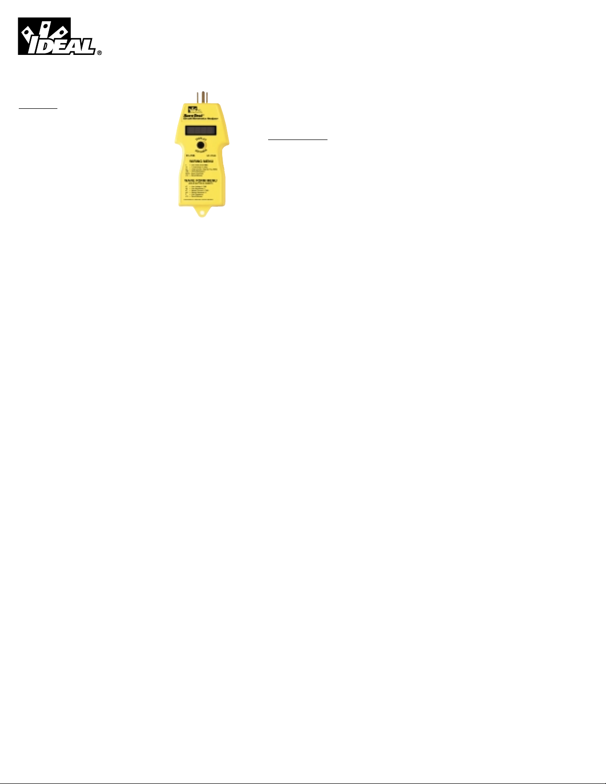
SureTest®Model ST-1TH D & ST-1THDC
Instructions
Introduction
The SureTest®family of Circuit/distortion analyzers
identify problems common to electrical circuits and
harmonic distortion quickly, easily and accurately.
They have a patented voltage drop test, which applies a
full 15-ampere load without causing interruption to
equipment on the circuit. This family also features 64K
of memory to store and recall up to 36 hours of testing.
Product Features
• Identifies and Locates
Loose Wire Connections
Bad Splices/Receptacles
High Resistance Grounds
False (Bootleg) Grounds
Shared Neutrals
• Verifies
Proper GFCI Operation
Dedicated Circuit Presence
Isolated Ground Presence (with the 61-176 Adapter)
• Measures
True RMS Line Voltage
Resistance of Hot and Neutral Conductors
Ground Impedance
% Voltage Drop by Conducting an Actual Full 15 Amp Load Test
% Voltage Drop by Simulating a 20 Amp Load Test
GFCI Trip Time
True RMS Neutral-to-Ground Voltage
Estimated Load on Circuit
Line Frequency
Power Consumption Power Factor
% Total Harmonic Distortion (THD) in the Line Voltage (to the 31st
Harmonic)
Product Features
• Measures
% THD in the Neutral Current (to the 31st Harmonic)
True RMS Current with the 61-181 Clamp Adapter (ST-1THDC)
• Event Recording
Captures up to 36 hours of testing
Min/Max/Avg/Peak Line Voltage
Resistance in Hot, Neutral, and Ground Conductors
Min/Max/Avg/Peak Neutral-to-Ground Voltage
% THD in the Line Voltage and Neutral Current
% THD per Harmonic up to the 31st Harmonic
Line Frequency
General Operation
The SureTest Models ST-1THD and ST-1THDC Circuit/Distortion Analyzers
take only seconds to test each outlet and circuit under a full load. The
ST-1THD features two easy to use operating menus. The Wiring Menu
gives access to measurements of line voltage, voltage drop at a full 15
amperes and 20 amperes, ground-to-neutral voltage, resistance of the hot a
neutral conductor, ground impedance. A ground fault circuit interrupter
(GFCI) test is also performed that will disrupt the electrical supply if a functional GFCI is present.
The Wave Form Menu gives access to measurements of % line voltage total
harmonic distortion (THD), line voltage harmonics to the 31st harmonic, %
neutral current THD, neutral current harmonics to the 31st harmonic and
line frequency.
In addition to these two programming menus, the ST-1THDC features a third
menu when used with the #61-181 Amp Clamp Adapter. The Clamp
Adapter Menu gives access to measurements of True RMS current, THD,
and harmonics to the 31st harmonic.
Any discrepancies from a normal reading indicate that a problem has been
detected in the circuit.
For use in 3-prong (grounded) outlets, inset the ST-1THD into the receptacle with the ground pin extended. For use in 2-prong (non-grounded) outlets, leave the ground pin retracted. In non-grounded (2-prong) outlets
many of the tests will be non-functional due to an absence of ground.
Page 2
4
WARNING
Do not use on outputs from UPS systems, light dimmers or square
wave generating equipment.
Insert the unit into the receptacle; observe test results and then move on to
the next receptacle. Allow at least 20 seconds between insertions.
Repeatedly inserting the SureTest into a receptacle will exceed its ability to
dissipate heat within the unit, resulting in fluctuating readings or damage to
the unit.
Wiring Verification
The St-1THD will test the wiring of a receptacle to identify if errors are present. Error messages will be displayed for polarity reversal, no ground, and
false ground conditions.
“E_rP” on the LED display indicates that the hot and neutral wires are
reversed.
“E_nG” on the LED display indicates that no ground is present. The ST1THD will not perform any of the tests involving the ground circuit if a no
ground condition is detected.
“E_FG” on the LED display indicates a false ground condition. False
ground is defined as a short between the ground and neutral wires very
close to the receptacle. A false ground may also be indicated if the receptacle is within 15 feet of the neutral-ground bonding point at the panel, or if
conduit is being used as the ground conductor.
Specifications
Case Construction: GE Cycolac plastic molded
Operating Range:
All measurements except
voltage drop, FG, drop, FG,
conductor resistances: 80-300 Volts AC @ 50-60 Hz
Voltage drop, False
Ground & Conductor
Resistances: 80-150 Volts
Harmonic Display: Odd, 3 - 15 + Bal. To 31
All Measurements: True R.M.S.
Specifications (continued)
Crest Factor: Peak / True R.M.S.
Memory Hold/Recall: 36 Hours
Power Use: 2 Watts continuous, 1800 W peak
Digital Display: Seven segment L.E.D., 3”
Accuracy, Display: 1% of full scale +/- 1 digit
Operating Temp: 0º C to 50º C
Storage Temp: -20º C to +65º C
Dimensions: 7” X 3” X 1.5”
Weight: 7 ounces
#61-181 Amp Clamp
Adapter: 3 to 500 Amps, Jaw opening -1.3 inches
Test Procedures
The programming menus feature a simple single button operation to
advance between various measurements. The programming set the measurements in a series of menu and submenu options to make navigation
through the menu structure easier.
3
®
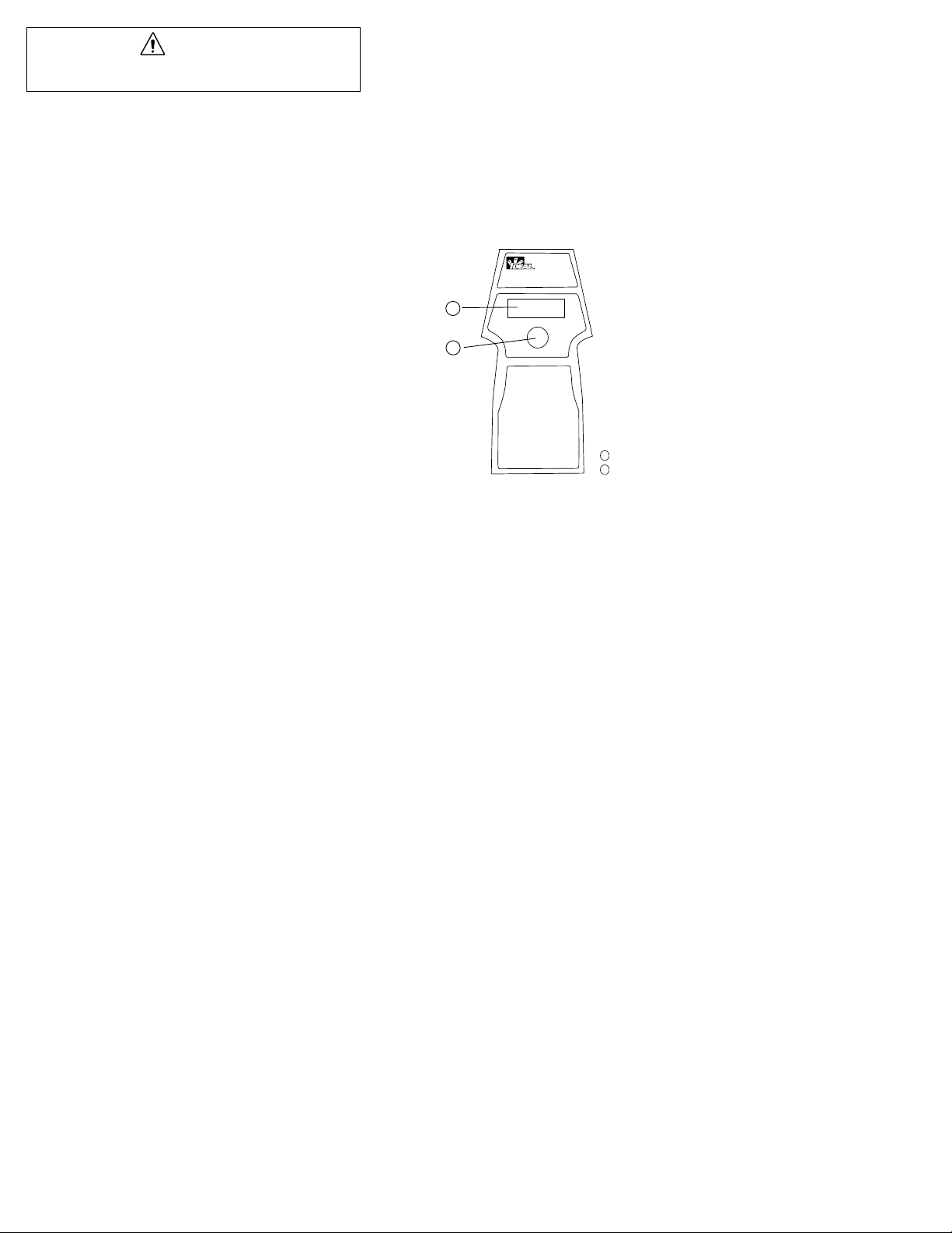
1
2
LED Display
Display Advance Button
1
2
SureTest
Circuit/Harmonics Analyzer
L
P
A
S
I
Y
D
A
E
D
C
V
N
A
61-156 ST-1THD
WIRING MENU
L = Line Volts (True RMS)
15 = % Volt Drop 15 Amp.
Gn = Volts Ground - Neutral (True RMS)
rES = Ohms Resistance
GFCI = Exact Trip Point
rCL = Recall Memory
WAVE FORM MENU
(HOLD BUTTON & INSERT)
LT = Line Voltage % THD
LH = Line Harmonics %
nT = Neutral Current % THD
nH = Neutral Harmonic %
F = Line Frequency
rCL = Recall Memory
Press Button for 3 Seconds to Access Sub Menu
Page 3
65
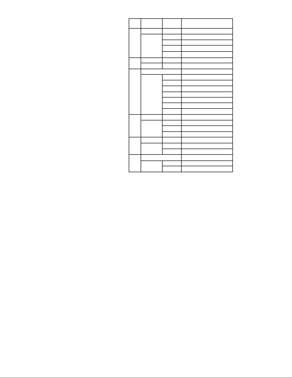
Menu Structure for Outlet Circuit Testing
Submenu
Display Menu Display Measurement
L- Line Voltage True RMS Line Voltage
Hi= Highest Line Voltage
Lo= Lowest Line Voltage
A= Average Line Voltage
P= Peak Line Voltage
15= Voltage Drop % Voltage Drop at 15 Ampere Load
20= % Voltage Drop at 20 Ampere Load
Gn= Ground-to-Neutral Voltage TRMS Ground-to-Neutral Voltage
Hi= Highest Ground-to-Neutral Voltage
Lo= Lowest Ground-to-Neutral Voltage
A= Average Ground-to-Neutral Voltage
P= Peak Ground-to-Neutral Voltage
ELL= Estimated Load on Circuit
Ld= Load (Watts)
PF= Power Factor of Load
rES= Resistance
rn= Neutral Conductor Resistance
rH= Hot Conductor Resistance
rG= Ground Impedance
GFCI= GFCI Trip time
Countdown
of Trip Time Testing GFCI Time to Trip
rCL= Recall Memory
Blinking rCL SureTest is Recording Data
Sto Recording Completed
Outlet Circuit Testing
Unless a wiring error exists, the ST-1THD will show "Out" in the LED display. This indicates that the unit is calibrating itself prior to testing. After
this calibration is performed, the ST-1THD automatically enters into the outlet circuit testing programming menu. The LED display cycles between the
menu heading, and the measurement every four seconds. Press and hold
the display advance button for one second to move to the menu. To enter
the submenu, press the display advance button for three seconds. To navigate from measurement to measurement within the submenu, press the display advance button. While in the submenu, pressing and holding the display advance button for three seconds brings the unit back to the menu
structure.
1. Insert the ST-1THD into the receptacle
2. The LED display shows “Out” indicating self-calibration of the unit
3. The LED display cycles between “L_”, indicating that True RMS Line
Voltage is being measured, and the Line Voltage measurement every four
seconds.
4. Press and hold the display advance button for three seconds to access
the Line Voltage submenu.
5. The LED display alternates between “Hi”, indicating that the highest line
voltage is being measured, and the measurement every four seconds
6. Press the display advance button for one second to move to the next test
within the Line Voltage submenu.
7. Press and hold the display advance button for three seconds to return to
the main menu.
Page 4
87
Line Voltage Menu
• Menu Heading - “L-”
• Measurement at Menu Heading - True RMS Line Voltage
• Submenu - yes
“Hi=” - Highest Line Voltage
“Lo=” - Lowest Line Voltage
“A=” - Average Line Voltage
“P=” - Peak Line Voltage
The submenu values are the highest, lowest, average and peak values taken
since the SureTest was plugged in.
Voltage Drop Menu
• Menu Heading - “Gn-”
• Measurement at Menu Heading - % Voltage Drop under a full 15 Amp
Load
• Submenu - yes
“20=” - Voltage Drop under 20 Amp Load
The test results for the 20 Amp load test are simulated based on an actual
15 Amp load.
Ground-to-Neutral Voltage Menu
Ground-to-neutral voltage results from current flowing in the neutral conductor from other equipment on the circuit. High ground-to-neutral voltage
indicates that the circuit may be loaded near its capacity or the neutral conductor may be shared or carrying harmonic distortion. A reading of less
than 2 volts usually indicates a usable outlet. An excessive ground-to-neutral voltage may result in inconsistent or intermittent equipment performance
This test can also be used to verify a dedicated circuit. A measurement
greater than 0.1 volts indicates that the receptacle under test is not on a
dedicated circuit.
• Menu Heading - “Gn-”
• Measurement at Menu Heading - True RMS Voltage, Ground-to-Neutral
• Submenu - yes
“Hi=” - Highest Ground-to-Neutral Voltage
“Lo=” - Lowest Ground-to-Neutral Voltage
“A=” - Average Ground-to-Neutral Voltage
“P=” - Peak Ground-to-Neutral Voltage
“ELL=” - Estimated Load on Circuit
“Ld=” - Load (Watts)
“PF=” - Power Factor of Load
The submenu values are the highest, lowest, average and peak values taken
since the SureTest was plugged in.
After the display is advanced to “Ld” in the submenu, it will cycle between
the load and power factor measurements. Pressing the display button will
not advance the unit through the programming sequence. After these measurements are taken, the unit must be removed from the receptacle and reinserted.
Resistance Menu
• Menu Heading - “rES-”
• Measurement at Menu Heading - None
• Submenu - yes
“rn=” - Resistance of Neutral Conductor
“rH=” - Resistance of Hot Conductor
“rG=” - Ground Impedance
The St-1THD checks ground impedance by pulsing 15 amperes from hot-toground to ensure that the resistance is less than 1 Ohm.
GFCI Menu
The ST-1D applies 6mA to ground through a fixed resistor to trip the GFCI.
A functional GFCI will disconnect the power. The reset may be at the outlet
or at the panel.
WARNING
When testing 3-wire outlets, do not proceed with the GFCI test if the
Wiring Indicator lights indicate a “No Ground” condition exists.
Repair the ground circuit first.
Page 5
109
GFCI Menu (continued)
• Menu Heading - “GFC=”
• Measurement at Menu Heading - None
• Submenu - No
Pressing the display advance button for three seconds will activate the GFCI
test. The ST-1THD applies 6mA to ground through a fixed resistor to trip
the GFCI. A functional GFCI will disconnect the power. The reset may be at
the outlet or at the panel. The tester will display the calculated time to trip,
apply the current and count up to the calculated time.
• If the GFCI is functioning properly, the circuit will disconnect, and the
LED display on the ST-1THD will go out. When the circuit is reset, and
power is returned, the LED display will show the actual time to trip.
• If the GFCI fails to trip, the LED display will show "bAd", which indicates
that the GFCI may be installed incorrectly, or the GFCI may be defective.
WARNING
In order to test GFCI’s in a 2-wire system (no ground wire), the #61-175
ground continuity adapter must be used. Connect the ground lead on
the adapter to a ground, such as a metal water or gas pipe.
Recall Memory Menu (Event Recording)
Stored data can be viewed from the Recall Memory menu. Pressing the display advance button for three seconds enters the submenu. The submenu is
identified by a blinking “rCL” on the LED display. Once in the submenu,
pressing the display advance button gives access to the stored values from
memory. These values are accessed through the outlet circuit testing menu.
While stored values are being displayed, the LED will blink to differentiate
these values from the “live” values being captured in standard testing mode.
Navigating through the outlet circuit testing menu while in recall memory
mode is identical to navigation through the menu in standard operation.
While the ST-1THD is in operation, the unit will analyze and store data on
the various measurements. These values can be permanently stored into the
memory from the Recall Memory submenu. Pressing the display advance
button for three seconds when a blinking “rCL” is shown on the display will
store all of the data into memory, overwriting any previous data in memory.
It is important to note that pressing the blinking "rCL" to exit viewing
recorded data stores new data into permanent memory. If you wish to maintain the stored data, but want to return to standard operation mode, unplug
the SureTest and re-insert it into the receptacle. The SureTest will return to
operation mode.
• Menu Heading - “rCL-”
• Measurement at Menu Heading - None
• Submenu - yes
Blinking “rCL” - Allows access to stored values from memory
“Sto” - Stores values into memory
Harmonic Wave Form Testing
To access the harmonic wave form programming menu, press the display
advance button and insert the ST-1THD into the receptacle. "HAr" will be
shown on the LED display . The LED display cycles between the menu
heading, and the measurement every four seconds. Press and hold the display advance button for one second to move to the menu. To enter the submenu, press the display advance button for three seconds. To navigate from
measurement to measurement within the submenu, press the display
advance button. While in the submenu, pressing and holding the display
advance button for three seconds brings the unit back to the menu structure.
1. Press the display advance button and insert the ST-1THD into the receptacle
2. The LED display shows “HAr” indicating self-calibration of the unit
3. The LED display cycles between “Lt_”, indicating that % Line Voltage
Total Harmonic Distortion (THD) is being measured, and the THD measurement every four seconds.
4. Press and hold the display advance button for three seconds to access
the Line Voltage submenu.
5. The LED display alternates between “Hi”, indicating that the highest distortion is being measured, and the measurement every four seconds
6. Press the display advance button for one second to move to the next test
within the % Line Voltage THD submenu.
7. Press and hold the display advance button for three seconds to return to
the main menu.
Page 6

12
11
Menu Structure for Wiring Harmonic Distortion Testing
Submenu
Display Menu Display Measurement
Lt- % Line Voltage THD Line Voltage THD
Hi= Highest Line Voltage THD
Lo= Lowest Line Voltage THD
A= Average Line Voltage THD
LC= Crest Factor
LH- Line Voltage Harmonics
h3= %THD at 3rd Harmonic
h5=...h15= % THD for each odd numbered
Harmonic through the 15th
Harmonic
bAL= Total of the remaining % THD from
17th Harmonic to 31st Harmonic
nt- % Neutral Current THD Neutral Current THD
Hi= Highest Neutral Current THD
Lo= Lowest Neutral Current THD
A= Average Neutral Current THD
nC= Crest Factor
nH- Neutral Current Harmonics
h3= %THD at 3rd Harmonic
h5=Öh15= Hot Conductor Resistance
bAL= Total of the remaining % THD from
17th Harmonic to 31st Harmonic
Frequency Value Line Frequency
rCL= Recall Memory
Blinking rCL SureTest is Recording Data
Sto Recording Completed
% Line Voltage THD Menu
• Menu Heading - “LT-”
• Measurement at Menu Heading - % Line Voltage THD
• Submenu - yes
“HI=” - Highest % THD
“Lo=” - Lowest % THD
“A=” - Average % THD
“LC=” - Crest factor of the line voltage
The submenu values are the highest, lowest, and average values taken since
the SureTest was plugged in.
Line Voltage Harmonics Menu
• Menu Heading - “LH-”
• Measurement at Menu Heading - None
• Submenu - yes
“h3=” - % THD at 3rd harmonic
“h5=” - % THD at 5th harmonic
“h7=”...”h15” - % THD is given for every odd harmonic to the 15th
harmonic
“bAL=” - Total of the remaining %THD from the 17th to 31st harmonic
% Neutral Current THD Menu
• Menu Heading - “nt-”
• Measurement at Menu Heading - % Neutral Current THD
• Submenu - yes
“Hi=” - Highest % THD
“Lo=” - Lowest % THD
“A=” - Average % THD
“nC=” - Crest factor of the neutral current
Neutral Current Harmonics Menu
• Menu Heading - “nC-”
• Measurement at Menu Heading - None
• Submenu - yes
“h3=” - % THD at 3rd harmonic
“h5=” - % THD at 5th harmonic
“h7=”...”h15” - % THD is given for every odd harmonic to the 15th harmonic
“bAL=” - Total of the remaining %THD from the 17th to 31st harmonic
Page 7

1413
Line Frequency
Within this menu selection, the ST-1THD displays the line frequency of the
current. There is no submenu for this menu selection.
Recall Memory Menu (Event Recording)
Stored data can be viewed from the Recall Memory menu. Pressing the
display advance button for three seconds enters the submenu. The submenu is identified by a blinking “rCL” on the LED display. Once in the submenu, pressing the display advance button gives access to the stored values from memory. These values are accessed through the outlet circuit
testing menu. While stored values are being displayed, the LED will blink
to differentiate these values from the "live" values being captured in standard testing mode. Navigating through the outlet circuit testing menu while
in recall memory mode is identical to navigation through the menu in standard operation.
While the ST-1THD is in operation, the unit will analyze and store data on
the various measurements. These values can be permanently stored into
the memory from the Recall Memory submenu. Pressing the display
advance button for three seconds when a blinking “rCL” is shown on the
display will store all of the data into memory, overwriting any previous data
in memory.
It is important to note that pressing the blinking “rCL” to exit viewing
recorded data stores new data into permanent memory. If you wish to
maintain the stored data, but want to return to standard operation mode,
unplug the SureTest and re-insert it into the receptacle. The SureTest will
return to operation mode.
• Menu Heading - “rCL”
• Measurement at Menu Heading - None
• Submenu - yes
Blinking “rCL” - Allows access to stored values from memory
“Sto” - Stores values into memory
Testing with the #61-181 Clamp Adapter
These tests can only be accessed by using the #61-181 amp clamp adapter
with the model ST-1THDC. Power must be supplied to the unit by an extension cord or battery pack to test the unit with the clamp adapter.
When the adapter is plugged into the ST-1THDC, the LED display will show
“Ct” indicating that the adapter is correctly plugged into the unit. The ST1THDC will then automatically enter into the current probe programming
menu. The LED display cycles between the menu heading, and the measurement every four seconds. Press the display advance button for one second
to move to the menu. To enter the submenu, press the display advance button for three seconds. To navigate from measurement to measurement within the submenu, press the display advance button. While in the submenu,
pressing and holding the display advance button for three seconds brings
the unit back to the menu structure.
1. Insert the #61-181 adapter into the ST-1THDC
2. The LED display shows “Ct” indicating recognition of the adapter
3. The LED display cycles between “cA”, indicating that True RMS current
is being measured through the amp clamp adapter, and the current measurement every four seconds.
4. Press and hold the display advance button for three seconds to access
the Current submenu.
5. The LED display alternates between “Hi”, indicating that the highest current is being measured, and the measurement every four seconds
6. Press the display advance button for one second to move to the next test
within the Current submenu.
7. Press and hold the display advance button for three seconds to return to
the main menu.
Page 8

1615
Menu Structure for Current Probe Menu Testing (ST-1THDC Only)
Submenu
Display Menu Display Measurement
cA- Current Current
Hi= Highest Current
Lo= Lowest Current
A= Average Current
ct- % Current THD % Current THD
Hi= Highest Current THD
Lo= Lowest Current THD
A= Average Current THD
P= Peak Current THD
cH- Current Harmonics
h3= %THD at 3rd Harmonic
H5=...H15= % THD for each odd numbered
Harmonic through the 15th
Harmonic
bAL= Total of the remaining % THD from
17th Harmonic to 31st Harmonic
Optional Accessories
#61-175 Ground Continuity Adapter
This adapter allows the operator to verify that a cabinet or equipment chassis has been properly connected to the power system ground. Plugging
into the #61-175 adapter will isolate the SureTest from the power source
ground. The LED display of the ST-1THD will read “E-nG”. If the equipment is properly grounded, then touching the alligator clip from the ground
continuity adapter to the cabinet or equipment chassis should return the circuit to a Normal condition.
WARNING
This is a static test and will not confirm the current carrying capacity
With the ST-1D, this adapter can be used to check the ground impedance of
a cabinet or equipment chasis. See section 3.4 for test instructions.
This adapter can also be used to test GFCI receptacles on 2-wire circuits.
Connect the ground lead on the adapter to a ground, such as a metal water
or gas pipe, prior to GFCI testing.
#61-176 Isolated Ground Adapter
This adapter allows the operator to verify that a receptacle is completely isolated from the other grounds between the receptacle and the entry panel.
WARNING
The receptacle should be tested for proper grounding prior to testing
for ground insulation.
Test the ground impedance of the receptacle and make a note of the results.
See the section on outlet circuit testing for details. Remove the SureTest
from the receptacle and plug it into the #61-176 adapter. Clip the ground
wire to the metal outlet, center receptacle screw, or the metal outlet box.
Re-insert the ST-1THD into the receptacle and retest for ground impedance.
Make a note of the result.
If the two resistance readings are the same, then the receptacle is not isolated. If the receptacle is isolated, the reading with the #61-176 will be lower.
A reading of half when the adapter is used is common, because a parallel
ground path has been introduced by attaching the ground wire to the
grounding point of the receptacle.
#61-177 Extension Cord
The ST-1THD is supplied with an extension cord to make testing easier on
hard-to-reach outlets. Replacement extension cords can be purchased from
your authorized IDEAL distributor.
#61-179 CARRYING CASE
The ST-1THD is supplied with a lightweight carrying case to protect the
units and store the instruction sheet and accessories. Replacement cases
can be purchased from your authorized IDEAL distributor.
Page 9
1817
#61-181 500AAC Clamp Adapter
This adapter can only be used with the ST-1THDC. This adapter is used for
True RMS current measurements up to 500-amperes. #61-158
Circuit/Harmonics Analyzer kit includes both the #61-157 Circuit/Harmonics
Analyzer and the #61-181 500AAC Clamp Adapter in one convenient package.
T
roubleshooting
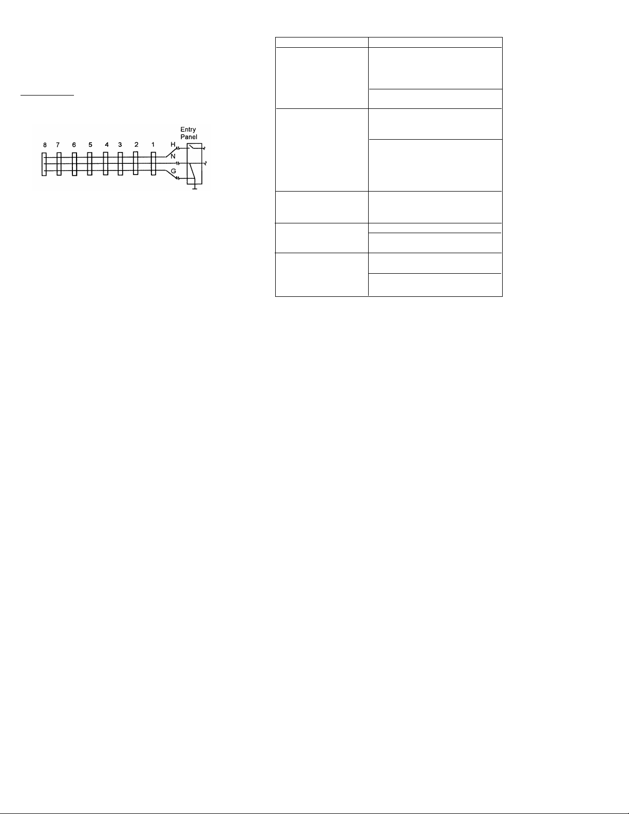
Locating Loose (High Resistance) Connectors and Splices
Loose connections, splices and bad connections can be isolated by using the
SureTest to test receptacles in sequence along the branch circuit.
For example if the voltage drop at receptacle 5 is unacceptable, checking the
other receptacles in the branch can help isolate the problem. If receptacles 1
through 4 and 6 through 8 check out OK, than further investigation should
take place at the connection to receptacle 5. The additional resistance could
be due to a loose connection/splice. If receptacles 6 through 8 are also
unacceptable, chances are that the problem is in either the hot or neutral
conductor in the wall between receptacles 4 and 5.
If all of the branch receptacles have unacceptable voltage drops, the problem
is most likely in the circuit between the panel and the first receptacle or at the
panel. If all branches are in high resistance, the problem may be in the circuit from the meter, or from the transformer to the service entrance.
Using the SureTest will help identify problem areas for further investigation
of the receptacles and/or branch circuit.
Troubleshooting Tips
Problem Possible Causes/Solutions
High/Low Line Voltage • Too much load on branch - also causing
excessive voltage drop
• Poor connection at receptacle
• Supply voltage too high/low
• Clean and tighten receptacle connections
• Consult power company
High Voltage Drop • Too much load on branch
(5% recommended by NEC) • Too many outlets on branch
• Diameter of wire too small
• Check and tighten connection at
receptacle
• Clean any corroded wires
• Replace outlet, switch
• Replace circuit breaker
High Ground-to-Neutral • Current flowing in the neutral conductor
Voltage (Greater than • Locate/repair source
2 Volts) • Install surge suppression
High Ground Impedance • Loose ground connection
(Greater than 1 Ohm) • Check and tighten ground connections
• Clean any corroded wires
Failure of GFCI Test • GFCI may be installed incorrectly
(GFCI will not trip) • GFCI may be defective
• Check for proper connections
• Replace outlet
Page 10

19
Other Sur
eTest Models from IDEAL
SureTest Circuit Analyzers
SureTest Circuit/Harmonics Analyzers
Warranty limited solely to repair or replacement; no warranty of merchantability, fitness for a particular purpose or consequential damages.
IDEAL INDUSTRIES, INC.
Sycamore, IL 60178, U.S.A.
800-435-0705 Customer Assistance
www.idealindustries.com
ND 2292-1 Made in U.S.A.
SureTest®Selection Guide
Identifies and Locates
Loose Wire Connections ••••
Bad Splices/Receptacles ••••
High Resistance Grounds ••••
False (Bootleg) Grounds •••
Shared Neutrals ••
Indicates
Proper Wiring in 3-Wire Receptacles ••••
Min/Max Line Voltage •••
Pass/Fail Voltage Drop •••
Pass/Fail Ground Impedance •
Pass/Fail Neutral-to-Ground Voltage •
Verifies
Dedicated Circuit Presence ••
Isolated Ground Presence (with #61-176 Adapter) •••
Proper GFCI Operation ••••
Measures
Line Voltage •••
Ground Impedance (Ohms) ••
% Voltage Drop under 15 ampere load •••
% Voltage Drop under 20 ampere load ••
GFCI Trip Time •••
Neutral-to-Ground Voltage ••
Estimated Load on Circuit (Amps) ••
Additional Features
220 VAC Operation •
61-150
ST-1
61-151
ST-1P+
61-152
ST-1D
61-153
ST-1D
SureTest®Selection Guide
Identifies and Locates
Loose Wire Connections •••
Bad Splices/Receptacles •• •
High Resistance Grounds •••
False (Bootleg) Grounds •••
Shared Neutrals •••
Verifies
Dedicated Circuit Presence •••
Isolated Ground Presence (with #61-176 Adapter) ••
Proper GFCI Operation •• •
Measures
Line Voltage •••
Ground Impedance (Ohms) •••
% Voltage Drop under 15 ampere load •••
% Voltage Drop under 20 ampere load •••
GFCI Trip Time •••
Neutral-to-Ground Voltage •••
Estimated Load on Circuit (Amps) •••
True RMS Measurements (Voltage) •• •
True RMS Measurements (Current)
(with #61-181 Adapter) • •
Line Frequency •••
Power Consumption (Watts) •••
Distortion to 31st Harmonic •••
Additional Features
220 VAC Operation
For use with #61-181 500AAC Adaptor ••
Included with #61-181 500AAC Adaptor •
Event recording •• •
61-156
ST-1THD
61-157
ST-1THDC
61-158
ST-1THDC
 Loading...