

Page 1

installation and
servicing
Mexico Super
Your Ideal installation and servicing guide
See reverse for
Mexico Super
users guide
ENGINEERED FOR PEACE OF MIND
When replacing any part on this appliance use only spare parts that you can be
assured conform to the safety and performance specification that we require. Do not
use reconditioned or copy parts that have not been clearly authorised by Ideal Boilers.
RS440, RS450 RS460 & RS470
May 2004 UIN 200 941 A02
Page 2
GENERAL
Table 1 - General Data
Boiler Size RS440 RS450 RS460 RS470
Gas Supply Connection in. BSP Rc 1/2 (1/2)
Number of Boiler Sections 2 3 3 3
Flow and Return Connections Rc 1 (1" BSP)
MAXIMUM Static Water Head m (ft.) 30.5 (100) (3 bar)
MINIMUM Static Water Head m (ft.) 1.0 (3.3)
Electrical Supply 230 V ~50 Hz
External Fuse Rating (Power Consumption) 3 A (5 W)
Water Content litre (gal.) 5.0 (1.1) 7.4 (1.6) 7.4 (1.6) 7.4 (1.6)
Dry Weight kg. (lb.) 71 (157) 93 (206) 93 (206) 93 (206)
Max. Inst Weight kg. (lb.) 64 (141) 87 (192) 87 (192) 87 (192)
Boiler Size Height mm (in.) 850 (33.5)
Width mm (in.) 440. (17.4)
Depth mm (in.) 533 (21.0)
Gas Type Natural 2 H
Gas Supply Pressure 20 mb
Table 2 - Performance Data
Boiler Size RS440 RS450 RS460 RS470
Boiler Input
Gas Consumption kW (Btu/h) 14.4 (49 100) 17.9 (61 100) 21.7 (74 000) 25.1 (85 600)
3
/h) 0.37 (47.3) 0.46 (58.9) 0.56 (71.3) 0.65 (82.5)
l/s (ft.
Boiler Output to Water kW (Btu/h) 11.7 (40 000) 14.7 (50 000) 17.6 (60 000) 20.5 (70 000)
Burner Setting Pressure (hot) mbar (in w.g.) 9.9 (4.0) 11.5 (4.6) 12.8 (5.1) 11.4 (4.6)
Flue Gas Flow Rate g/s 6.7 8.3 10.2 11.8
O
Flue Gas Temperature
C 102 107 119 137
*Seasonal Efficiency (SEDBUK) Band D [78.5]% [79.0]% [78.9]% [78.9]%
*The value is used in the UK government's Standard Assessment Procedure (SAP) for energy rating of dwellings.
The test data from which it has been calculated have been certified by Advantica 0087.
Note.
Key to symbols
Gas consumption is calculated using a calorific value of 38.7 MJ/
m3 (1038 Btu/ft3) gross or 34.9 MJ/m3 (935 Btu/ft3) nett. To obtain
the gas consumption at a different calorific value:-
IE = Ireland (Countries
GB = United Kingdom of destination)
a. For l/s - divide the gross heat input (kW) by the gross C.V. of
the gas (MJ/m
3
b. For ft
/h - divide the gross heat input (Btu/h) by the gross C.V.
3
)
of the gas (Btu/ft3)
PMS = Maximum operating pressure of water
= A room sealed appliance designed for connection via ducts
C
11
to a horizontal terminal, which admits fresh air to the burner
and discharges the products of combustion to the outside
without a fan in the combustion products circuit.
c. The appliance is preset at the factory to the highest nominal
rating.
= An appliance designed for use on 2nd Family gas, Group H
I
2H
only.
CAUTION. To avoid the possibility of injury during the installation, servicing or cleaning of this
appliance, care should be taken when handling edges of sheet steel components.
2
Mexico Super RS440 - RS470 - Installation & Servicing
Page 3

GENERAL
CONTENTS
Air Supply. ............................................................................. 6
Boiler Assembly - Exploded view ...................................... 11
Boiler Clearances .................................................................5
Burner Assembly - Exploded view .................................... 35
Electrical Connections ....................................................... 17
Electrical Diagram ..............................................................17
Electrical Supply ................................................................... 7
Fault Finding ........................................................................30
Flue Fitting ...........................................................................15
Flue Installation ..................................................................... 6
Gas Safety Regulations ........................................................ 4
Gas Supply ............................................................................ 6
Initial Lighting ......................................................................21
Installation .......................................................................... 11
Mandatory Requirements ....................................................4
Pump ..................................................................................... 8
Servicing ............................................................................. 23
Short List of Parts .............................................................. 31
System Diagrams (Electrical) ............................................ 18
Terminal Guards. .................................................................. 6
Terminal Sizes. ................................................................... 14
Water Connections ..................................................... 4 & 16
Water Systems ..................................................................... 8
Water Treatment ................................................................16
Mexico Super RS
B.G. Certified - P.I. No. 87AT14
Destination Countries: GB & IE Appliance type: C
Models G.C. Appliance No.
Mexico Super RS440 ..................... 41 392 74
Mexico Super RS450 ..................... 41 392 75
Mexico Super RS460 ..................... 41 392 76
Mexico Super RS470 ..................... 41 392 77
Natural Gas only
11
INTRODUCTION
The Mexico Super RS range is of floor standing, natural
draught, balanced flue gas boilers. They are rated to provide
central heating outputs of 11.7 kW (40,000 Btu/h) to 20.5 kW
(70,000 Btu/h).
The boiler has a cast iron heat exchanger and is supplied fully
assembled, complete with a white enamelled mild steel
casing.
A door at the top of the casing front panel hinges down, revealing
the boiler thermostat control (and programmer, if fitted).
The boilers are suitable, as standard, for connection to openvented systems ONLY - an overheat thermostat kit is available
to allow the boiler to be used on sealed water systems.
The systems may be:
• pumped or gravity circulating indirect DHW only
• pumped central heating only
• pumped central heating combined with either a pumped or
gravity circulating indirect DHW circuit.
For GB, to comply with Building Regulations Part L1 (Part J in Scotland) the boiler should be fitted in accordance with the
manufacturer's instructions. Self-certification that the boiler has been installed to comply with Building Regulations can be
demonstrated by completing and signing the Benchmark log book.
BENCHMARK LOG BOOK DETAILS
Boiler Page
Make and model ....................................................... 3
Appliance serial no. on data badge ........................ 11
SEDBUK No. % .........................................................2
Controls
Time and temperature control to heating ......... 18/19
Time and temperature control to hot water ...... 18/19
Heating zone valves .......................................... 18/19
TRV's ......................................................................... 7
Auto bypass ............................................................... 7
Boiler interlock ..........................................................7
For all boilers
Flushing to BS.7593 .............................................. 16
Inhibitor ................................................................... 16
Central heating mode
Heat input ................................................. to be calculated
Burner operating pressure ....... measure and record
Central heating flow temp. ........ measure and record
Central heating return temp. ..... measure and record
For combination boilers only
Scale reducer ......................................................... n/a
Hot water mode
Heat input ............................................................... n/a
Max. operating burner pressure ............................n/a
Max. operating water pressure ..............................n/a
Cold water inlet temp ............................................. n/a
Hot water outlet temp. ............................................n/a
Water flow rate at max. setting ............................... n/a
For condensing boilers only
Condensate drain .................................................. n/a
For all boilers: complete, sign & hand over to customer
For assistance see Technical Helpline on the back page
Page
NOTE TO THE INSTALLER:
LEAVE THESE
INSTRUCTIONS ADJACENT TO THE GAS METER.
ALSO COMPLETE THE BENCHMARK LOG BOOK
AND GIVE THIS TO THE CUSTOMER.
Mexico Super RS440 - RS470 - Installation & Servicing
3
Page 4

GENERAL
This boiler may require 2 or more operatives to move it to its
installation site, remove it from its packaging base and during
movement into its installation location. Manoeuvring the boiler
may include the use of a sack truck and involve lifting, pushing
and pulling. The use of 1” pipe stubs of suitable lengths may
be temporarily screwed into the boiler tappings to act as
handles.
Caution should be exercised during these operations.
Operatives should be knowledgeable in handling techniques
when performing these tasks and the following precautions
should be considered:
• Split the boiler down to reduce the weight, e.g. remove
casing and hardware pack. Refer to Frame 9.
• Be physically capable.
• Use PPE as appropriate, e.g. gloves, safety footwear.
During all manoeuvres and handling actions, every attempt
should be made to ensure the following unless unavoidable
and/or the weight is light.
• Keep back straight.
• Avoid twisting at the waist.
• Avoid upper body/top heavy bending.
• Always grip with the palm of the hand.
• Use designated hand holds.
• Keep load as close to the body as possible.
• Always use assistance if required.
OPTIONAL EXTRA KITS
Programmer Kit
Fits neatly within the casing. Separate fitting instructions are
included with this kit.
Overheat Available to allow the boiler to be used
Thermostat Kit on sealed water systems.
GAS SAFETY
CURRENT GAS SAFETY (INSTALLATION AND USE)
REGULATIONS OR RULES IN FORCE.
The appliance is suitable only for installation in GB and IE and
should be installed in accordance with the rules in force.
In GB, the installation must be carried out by a CORGI
Registered Installer, or in IE a competent person. It must be
carried out in accordance with the relevant requirements of the:
• Gas Safety (Installation and Use) Regulations
• The appropriate Building Regulations either The Building
Regulations, The Building Regulations (Scotland), Building
Regulations (northern Ireland).
• The Water Fittings Regulations or Water byelaws in
Scotland.
• The Current I.E.E. Wiring Regulations.
Where no specific instructions are given, reference should be
made to the relevant British Standard Code of Practice.
In IE, the installation must be carried out by a Competent
Person and installed in accordance with the current edition of
I.S.813 "Domestic Gas Installations", the current Building
Regulations and reference should be made to the current ETCI
rules for electrical installation.
Detailed recommendations are contained in the following British
Standard Codes of Practice:
BS. 6891 Low pressure installation pipes.
BS. 6798 Installation of gas fired hot water boilers of rated
input not exceeding 60 kW.
BS. 5449:1 Forced circulation hot water systems (small bore and
microbore domestic central heating systems).
BS. 5546 Installation of gas hot water supplies for domestic
purposes (2nd Family Gases).
BS. 5440: 1 Flues for gas appliances of rated input not
exceeding 60 kW.
BS. 5440: 2 Ventilation for gas appliances of rated input not
exceeding 60 kW.
BS 7593 Treatment of water in Domestic Hot Water Central
Heating Systems.
Health and Safety Document No. 635.
The Electricity at Work Regulations, 1989.
Manufacturer’s notes must NOT be taken in any way as overriding
statutory obligations.
IMPORTANT. These appliances are certificated by the British
Standards Institution for safety and performance. It is important,
therefore, that no external control devices, e.g. flue dampers,
economisers etc., are directly connected to these appliances unless
covered by these Installation and Servicing Instructions or otherwise
recommended by Caradon Ideal Limited in writing. If in doubt please
enquire.
Any direct connection of a control device not approved by Caradon
Ideal Limited could invalidate the BSI Certification and the normal
appliance warranty. It could also infringe the Gas Safety Regulations
and the above regulations or other statutory requirements.
SAFE HANDLING OF SUBSTANCES
Care should be taken when handling the boiler insulation panels,
which can cause irritation to the skin. No asbestos, mercury or
CFCs are included in any part of the boiler.
LOCATION OF BOILER
The boiler must be installed on a flat and level floor, capable of
adequately supporting the weight of the boiler and any ancillary
equipment.
The boiler may be fitted on a combustible floor.
Insulation is not necessary, unless required by the local authority.
The boiler must not be fitted outside.
Timber Framed Buildings
If the boiler is to be fitted in a timber framed building it should be
fitted in accordance with the Institute of Gas Engineering
document IGE/UP/7:1998.
Bathrooms
The boiler may be installed in any room or internal space,
although particular attention is drawn to the requirements of the
current I.E.E. (BS 7671) Wiring Regulations and, in Scotland, the
electrical provisions of the building regulations applicable in
Scotland with respect to the installation of the boiler in a room or
internal space containing a bath or shower. For Ireland reference
should be made to the current ETCI rules for electrical
installations and I.S. 813: 2002.
Where a room-sealed appliance is installed in a room containing
a bath or shower then the appliance and any electrical switch or
appliance control utilising mains electricity should be so situated
that it cannot be touched by a person using the bath or shower.
Where installation will be in an unusual location, special
procedures may be necessary and BS.6798 gives detailed
guidance on this aspect.
Compartment Installations
A compartment used to enclose the boiler MUST be designed
and constructed specially for this purpose.
An existing cupboard or compartment may be used, providing it is
modified for the purpose.
4
Mexico Super RS440 - RS470 - Installation & Servicing
Page 5
1
BOILER WATER CONNECTIONS
1. This appliance is NOT suitable for use in
a direct hot water system.
2. If the boiler is to be used on a sealed
system, an Overheat Thermostat Kit is
available and must be installed in
accordance with the instructions
supplied with the kit.
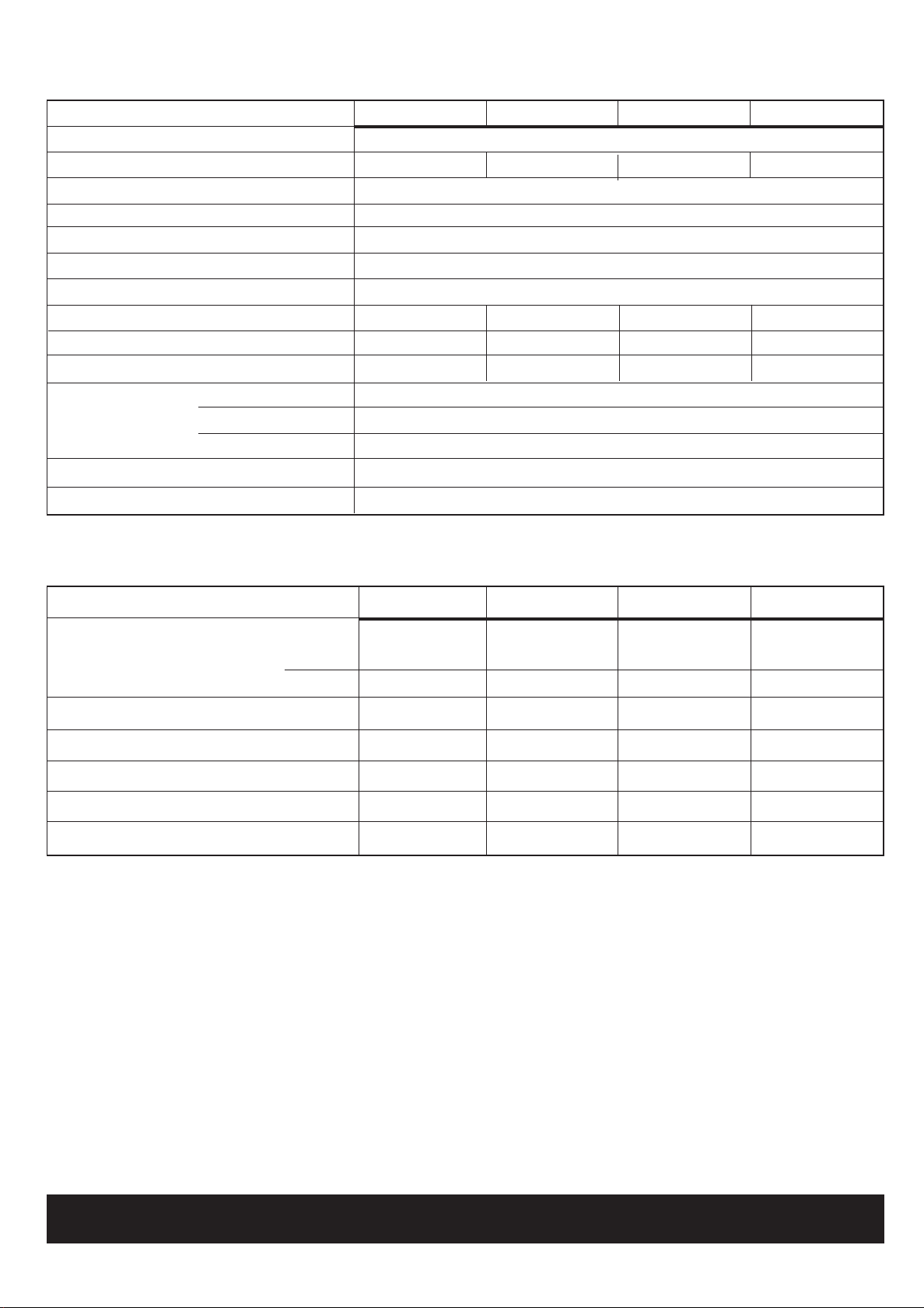
Boiler Dimension A
RS440 152mm (6")
RS450, RS460 226mm (8 7/8")
RS470
GENERAL
2
FLOOR MOUNTING AND BOILER CLEARANCES
Flammable materials must not be placed in close proximity
to the appliance. Materials giving off flammable vapours
must not be stored in the same room as the appliance.
Floor mounting
1. The floor must be flat, level and of suitable load bearing
capacity.
2. The back of the boiler may be fitted up to the wall.
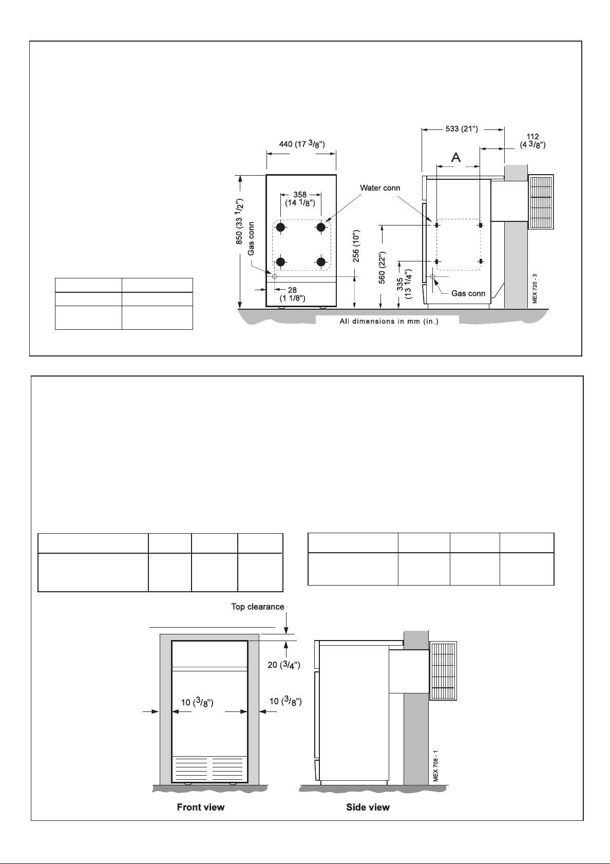
Boiler clearances
The minimum overall dimensions of the space in which the
boiler is to operate and to facilitate servicing are as follows:-
Boiler Size Width Depth Height
RS440, RS450, 460 mm 533 mm 870 mm
RS460 & RS470. (18") (21") (34 1/4")
Additional space will be required for installation, depending
upon site conditions.
IMPORTANT.
In order to facilitate gas connection, a clearance of at least
100 mm (4") must be available at either the LH side or the
RH side DURING installation. Refer to Frame 14.
In addition a MINIMUM clearance of 533 mm (21") MUST be
available at the front of the boiler, for servicing.
Terminal sizes
Boiler Size Depth Height Width
RS440, RS450, 152 338 372
RS460 & RS470
Mexico Super RS440 - RS470 - Installation & Servicing
5
Page 6
GENERAL
In both cases details of essential features of cupboards/
compartment design, including airing cupboard installation,
are to conform to the following:
!!
! BS. 6798.
!!
!!
!
The position selected for installation MUST allow
!!
adequate space for servicing in front of the boiler
and for air circulation around the boiler.
Side clearance is only necessary for installation. The amount
of side clearance will depend upon the type of connection used.
! This position MUST also permit the provision of a satisfactory
flue termination.
! For the minimum clearances required for safety, and
subsequent service, see Frame 2.
GAS SUPPLY
The local gas supplier should be consulted, at the installation
planning stage, in order to establish the availability of an adequate
supply of gas. An existing service pipe must NOT be used without
prior consultation with the local gas supplier.
The boiler is to be installed only on a gas supply with a governed meter.
A gas meter can only be connected by the local gas supplier or by
a local regional contractor.
Check that the appliance is suitable for the proposed gas
supply. An existing meter should be checked, preferably by the
gas supplier, to ensure that the meter is adequate to deal with
the rate of gas supply required. A minimum gas pressure of
20 mbar MUST be available at the boiler inlet, with the boiler
operating.
Installation pipes MUST be fitted in accordance with BS. 6891. In
IE refer to I.S. 813:2002. Pipework from the meter to the boiler
MUST be of an adequate size.
The complete installation MUST be tested for gas soundness
and purged as described in the above code.
Table 3 - Balanced flue terminal position
Terminal Position
1a. Directly BELOW an opening, 600
air brick,opening window etc. (24") (60")
1b. Directly ABOVE an opening, 300
air brick,opening window etc. (12") (12")
1c. HORIZONTALLY to an opening, 400
air brick,opening window etc. (16") (24")
2. Below guttering, drain pipes or soil
pipes 300 mm (12")
3. Below eaves 300 mm (12")
4. Below balconies or a car port roof 600 mm (24")
From vertical drain pipes or soil pipes
5.
6. From an internal or external corner or
to a boundary alongside the terminal 600 mm (24")
7. Above adjacent ground, roof or
balcony level 300 mm (12")
8. From a surface or a boundary
facing the terminal 600 mm (24")
9. From a terminal facing a terminal 600 mm (24")
10. From an opening in a car port
(e.g. door or window) into dwelling 1200 mm (48")
11. Vertically from a terminal on the
same wall 1500 mm (60")
Horizontally from a terminal on the wall
12.
Minimum Spacing
440
450,460,470
mm
1500
mm
mm
300 mm
mm
600
mm
300 mm (12")
300 mm (12")
FLUE INSTALLATION
Some pluming may occur at the termination so terminal positions
where this could cause a nuisance should be avoided.
The flue must be installed in accordance with the
recommendations of BS. 5440-1:2000. In IE refer to I.S.
813:2002.
The following notes are intended for general guidance:-
1. The boiler MUST be installed so that the terminal is exposed
to external air.
2. It is important that the position of the terminal allows the free
passage of air across it at all times.
3. Minimum acceptable spacing from the terminal to
obstructions and ventilation openings are specified in
Table 3.
4. Where the lowest part of the terminal is fitted less than 2m (6'
6") above a balcony, above ground or above a flat roof to which
people have access then the terminal MUST be protected by a
purpose designed guard.
Terminal guards are available from boiler suppliers. In case of
difficulty seek advice from:
Grasslin (UK) Ltd., Tower House, Vale Rise, Tonbridge, Kent
TN9 1TB.
Tel: +44 (0) 1732 359 888. Fax: +44 (0) 1732 354 445
www.tfc-group.co.uk
Ensure that the guard is fitted centrally
5. Where the terminal is fitted within 1000mm (39 1/2") of a
plastic or painted gutter or 500mm (19 1/2") of painted eaves
then an aluminium shield at least 1000mm (39 1/2") long
should be fitted to the underside of the gutter or painted
surface.
6. The air inlet/products outlet duct and the terminal of the boiler
MUST NOT be closer than 25mm (1") to combustible material.
Detailed recommendations on the protection of combustible
material are given in BS. 5440-1:2000.
In IE refer to I.S.
813:2002.
IMPORTANT.
It is absolutely ESSENTIAL to ensure, in practice, that products of
combustion discharging from the terminal cannot re-enter the
building or any other adjacent building through ventilators, windows,
doors, other sources of natural air infiltration or forced ventilation/air
conditioning. If this should occur, the appliance MUST be turned
OFF, labelled 'unsafe' and corrective action taken.
TERMINAL
The terminal assembly can be adapted to accommodate various
wall thicknesses. Refer to Frame 8.
AIR SUPPLY
Detailed recommendations for air supply are given in BS.5440:2. In
IE refer to I.S. 813:2002.
The following notes are for general guidance:
1. It is NOT necessary to have a purpose provided air vent in the
room or internal space in which the boiler is installed.
2. If the boiler is to be installed in a cupboard or compartment,
permanent air vents are required (for cooling purposes) in the
cupboard/compartment, at both high and low levels. The air vents
must either communicate with room/internal space, or be direct
to outside air. The minimum effective areas of the permanent air
vents, required in the cupboard/compartment, are specified as
follows and are related to maximum rated heat input.
6
Mexico Super RS440 - RS470 - Installation & Servicing
Page 7
GENERAL
FLOW RATE (l/min)
FLOW RATE (gals/hr.)
PRESSURE LOSS (ft. water)
PRESSURE LOSS (mbar)
RS 440
RS 450
RS 460
RS 470
RS 440
RS 450 & RS 460
RS 470
Mex 1945
3. Both air vents MUST communicate with the same room or internal
space or MUST be on the same wall to outside air.
4. In siting the air vents care must be taken to avoid the freezing of
pipework.
Table 4 - High and low vent areas
Boiler Air from room/internal Air direct from
space cm
2
(in.2) outside cm2 (in.2)
High level Low level High level Low level
RS440 143 (23) 143 (23) 72 (12) 72 (12)
RS450 173 (27) 173 (27) 87 (14) 87 (14)
RS460 208 (33) 208 (33) 104 (17) 104 (17)
RS470 245 (38) 245 (38) 123 (19) 123 (19)
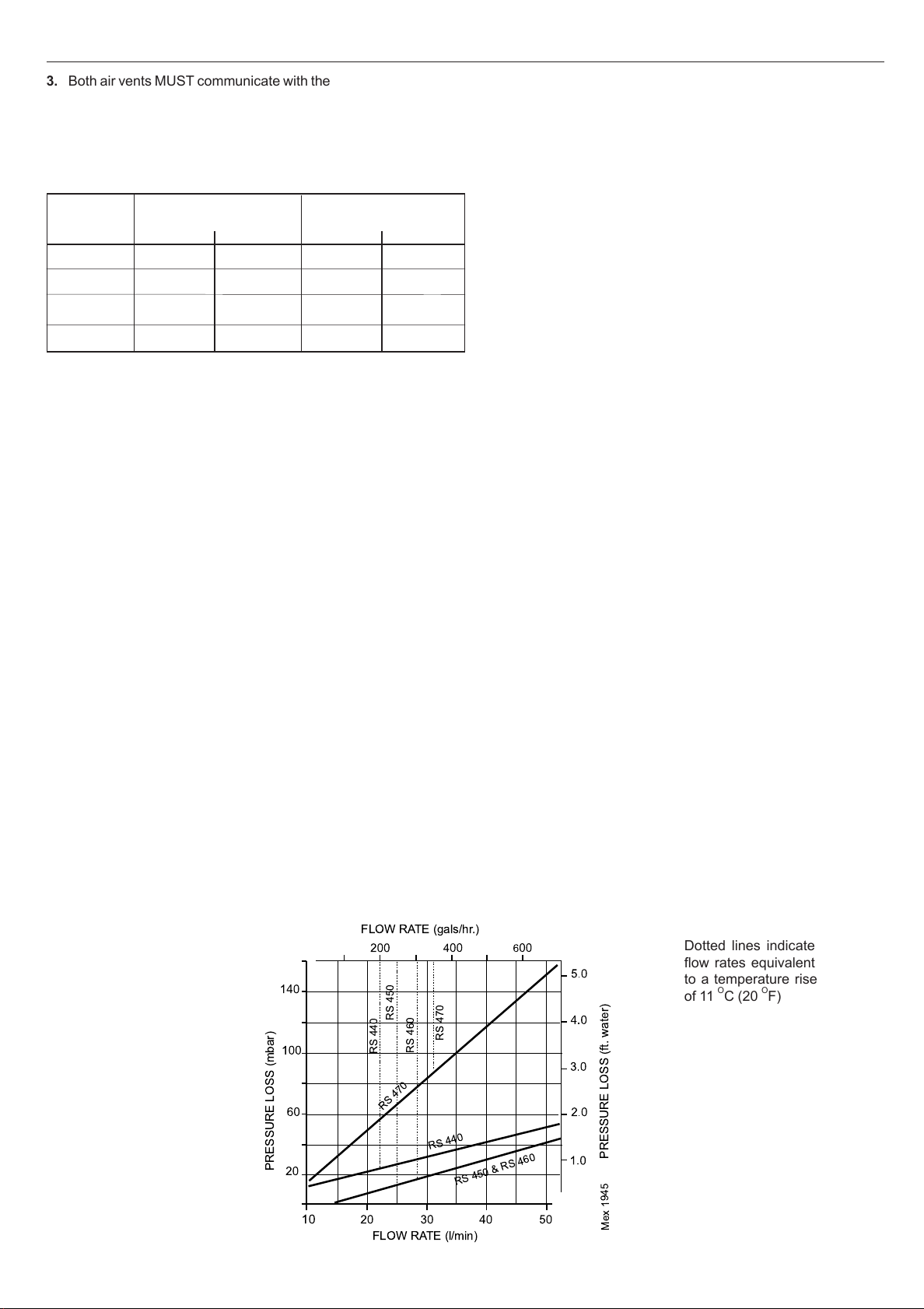
WATER CIRCULATION SYSTEM
The boiler must NOT be used for direct hot water supply. The boiler
is suitable for connection to pumped open vent central heating
systems, pumped central heating combined with pumped or gravity
indirect domestic hot water supply systems.
The boiler is NOT suitable for gravity heating systems. The hydraulic
resistance of the boilers at maximum output with 11 OC (20 OF)
temperature differentials are shown in the graph below.
The central heating system should be in accordance with
BS. 6798 and, in addition, for smallbore and microbore systems,
BS. 5449:1.
The domestic hot water system, if applicable, should be in
accordance with the relevant recommendations of BS. 5546.
Copper tubing to BS. 2871:1 is recommended for water carrying
pipework.
The hot water storage cylinder MUST be of the indirect type and
should preferably be manufactured of copper.
Single feed, indirect cylinders are not recommended and MUST
NOT be used on sealed systems.
The hot water cylinder and ancillary pipework not forming part of the
useful heating surface should be lagged to prevent heat loss and
any possible freezing - particularly where pipes run through roof
spaces and ventilated underfloor spaces.
IMPORTANT
A minimum length of 2 metres of copper pipe MUST be fitted to
both flow and return connections from the boiler before
connection to any plastic piping.
The boiler must be vented. If venting cannot be done via a flow
connection a separate vent MUST be fitted by the installer.
Draining taps MUST be located in accessible positions, which
permit the draining of the whole system - including the boiler
and hot water storage vessel. They should be at least 1/2" BSP
nominal size and be in accordance with BS. 2879.
If required, a drain tap (not supplied) may be fitted to an
unused bottom (1" BSP) tapping on the front of the boiler.
BOILER CONTROL INTERLOCKS
Caradon Ideal Limited recommend that heating systems utilising
full thermostatic radiator valve control of temperature in individual
rooms should also be fitted with a room thermostat controlling
the temperature in a space served by radiators not fitted with
such a valve as stated in BS. 5449.
Central heating systems controls should be installed to ensure the
boiler is switched off when there is no demand for heating or hot water.
When thermostatic radiator valves are used, the space heating
temperature control over a living / dining area or hallway having a
heating requirement of at least 10% of the boiler heat output
should be achieved using a room thermostat, whilst other rooms
are individually controlled by thermostatic radiator valves.
However, if the system employs thermostatic radiator valves on
all radiators, or two port valves without end switches, then a
bypass circuit must be fitted with an automatic bypass valve to
ensure a flow of water should all valves be in the closed position.
ELECTRICAL SUPPLY
WARNING. The appliance MUST be efficiently earthed.
Wiring external to the appliance MUST be in accordance with the
current I.E.E. (BS 7671) Wiring Regulations and any local
regulations which apply. For Ireland reference should be made
to the current ETCI rules for electrical installations.
The boiler is supplied for 230 V ~ 50 Hz single phase. The fuse
rating is 3A.
Connection must be made in a way that allows complete isolation
of the electrical supply - such as a double pole switch, having a
1/8") contact separation in both poles, or a plug and socket
3mm (
serving only the boiler and system controls.
The means of isolation must be accessible to the user after
installation.
For bathroom installations the point of connection to the mains
must be situated outside the bathroom.
Water Flow Rate and Pressure Loss
Mexico Super RS440 - RS470 - Installation & Servicing
Dotted lines indicate
flow rates equivalent
to a temperature rise
of 11 OC (20 OF)
7
Page 8
GENERAL
3
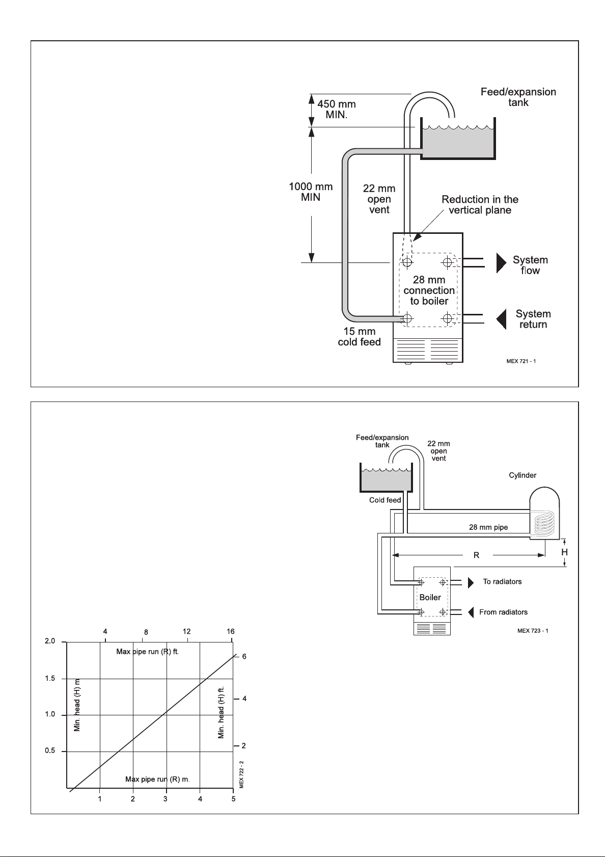
MINIMUM REQUIREMENTS Fully pumped systems
1. Open vent and cold feed connections must be made to
the boiler flow and return tappings according to the
options shown in Frame 11.
2. The boiler is assumed to be the highest point of the
circulating system.
3. The circulating pump is positioned on the FLOW and
the vertical distance, between the pump and feed/
expansion tank, must comply with the pump
manufacturer's minimum requirements, to avoid
cavitation. Should these conditions not apply, either
lower the pump position or raise the feed/ expansion
tank above the minimum requirements of Caradon Ideal
Limited.
4. The water velocity through the boiler flow / return pipes
is assumed to be below 1 m/s (3 ft./s), whilst the pump
flow rate is set to provide a temperature difference of
o
C (20 oF) across the boiler flow / return, at design
11
input.
5. This information is intended as a GUlDE ONLY and
cannot take into account instantaneous changes in
head caused by the operation of motorised valves,
pumps etc.
Due allowance MUST be made if surging is liable to
occur.
If in any doubt, contact Caradon Ideal Limited.
4
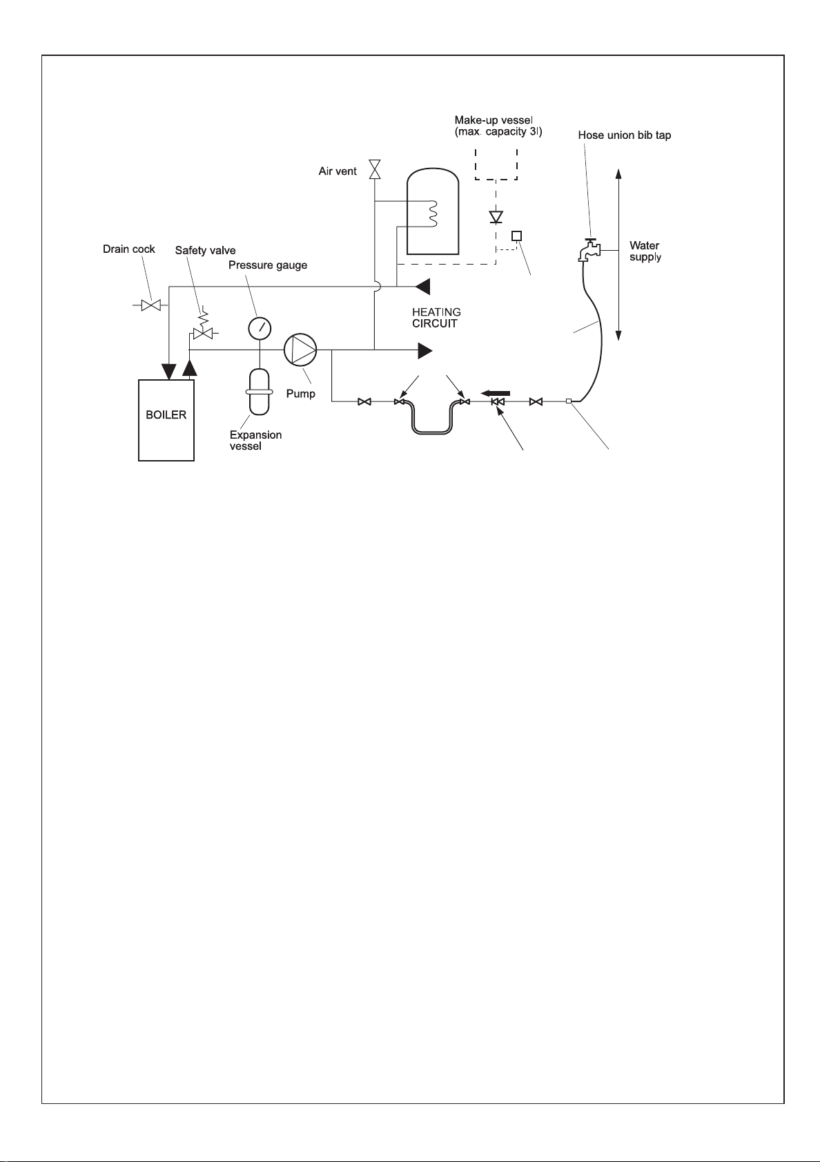
GRAVITY HOT WATER & PUMPED CENTRAL HEATING
1. Separate flow and return connections are used for each service. All
possible configurations are given in Frame 11 and ONLY those
shown should be used.
2. The schematic pipework graph is based on the assumption that
NO MORE than 8 elbows are used in the gravity loop, including
entry to the boiler.
3. For each extra elbow in excess of 8 (R) MUST be reduced by 300
mm (12") or (H) increased by 100 mm (4")
4. Whatever value is selected for (R), the value of (H) MUST be at least
that indicated by the graph.
(R) = the horizontal distance between the centre line of the cylinder
and the boiler tappings used - measured along the pipe run.
(H) = the vertical distance between the top of the boiler and the
base of the cylinder.
Notes.
a. Flow and return pipes should rise vertically on leaving
b. Horizontal pipes should be ABOVE ceiling level and as
c. A MINIMUM inclination of 25 mm per 3 m run (1" per 10')
If the above conditions cannot be met pumped primaries
should be used.
the boiler.
short as possible.
is required to avoid air locks.
8
Mexico Super RS440 - RS470 - Installation & Servicing
Page 9
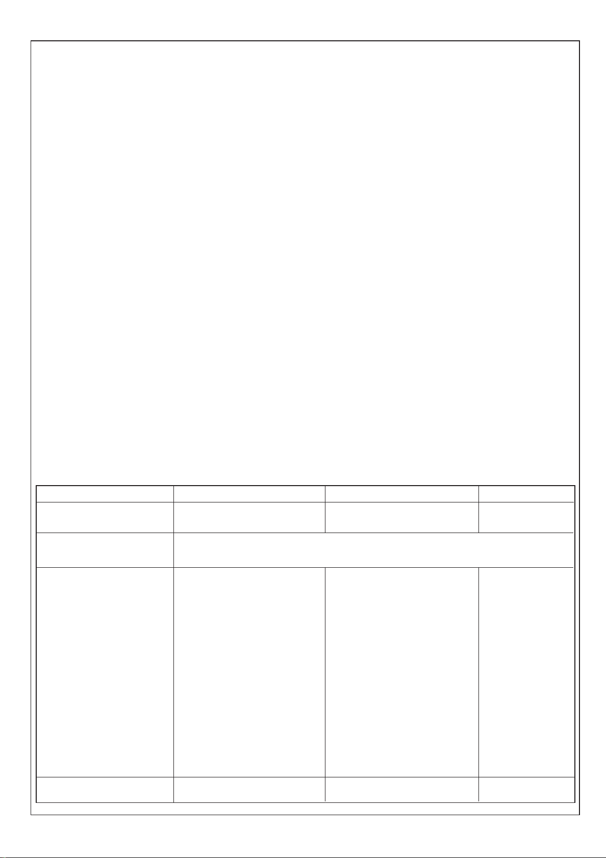
SEALED SYSTEM REQUIREMENTS
5
ecl6060
GENERAL
Hose unions
Temporary hose
(disconnect
after filling)
Non-return
valve
Automatic
air vent
Hosepipe
(disconnect
after filling)
Additional
stop valve
Double check valve
assembly
(note direction of flow)
Hose connector
Note.
The method of filling, refilling, topping up or flushing sealed
primary hot water circuits from the mains via a temporary hose
connection is only allowed if acceptable to the local water
authority.
1. General
a. The installation must comply with the requirements of
BS.6798 and BS.5449.
b. The installation should be designed to work with flow
temperatures of up to 82
o
C.
c. All components of the system, including the heat
exchanger of the indirect cylinder, must be suitable for a
working pressure of 3 bar (45 lb/in
2
) and temperature of
110oC. Care should be taken in making all connections
so that the risk of leakage is minimised.
2. Safety Valve
A spring loaded safety valve complying with the relevant
requirements of BS.6759 must be fitted in the flow pipe, as
close to the boiler as possible and with no intervening valve
or restriction. The valve should have the following features:
a. A non-adjustable preset lift pressure not exceeding 3 bar
(45 lb./in
2
)
b. A manual testing device.
c. Provision for connection of a discharge pipe. The valve
or discharge pipe should be positioned so that the
discharge of water or steam cannot create a hazard to
the occupants of the premises or cause damage to
electrical components and wiring.
3. Pressure Gauge
A pressure gauge covering at least the range 0-4 bar (0-60
lb./in2) must be fitted to the system. The gauge should be
easily seen from the filling point and should preferably be
connected at the same point as the expansion vessel.
4. Expansion Vessel
a. A diaphragm type expansion vessel must be
connected at a point close to the inlet side of the
pump, the connecting pipe being not less than 15mm
1/2" nominal) size and not incorporating valves of any
(
sort.
b. The vessel capacity must be adequate to accept the
expansion of the system water when heated to 110
(230oF)
c. The charge pressure must not be less than the static
water head above the vessel The pressure attained in
the system when heated to 110
least 0.35 bar (5lb/in
2
) less than the lift pressure of the
o
C (230oF) should be at
safety valve.
For guidance on vessel sizing refer to Table 5, Frame 6.
For further details refer to BS.5449. For IE refer to the
current edition of I.S. 813.
5. Cylinder
The cylinder must be either of the indirect coil type or a
direct cylinder fitted with an immersion calorifier which is
suitable for operating on a gauge pressure of 0.35 bar
2
(5lb./in
) in excess of the safety valve setting. Single feed
indirect cylinders are not suitable for sealed systems.
6. Make-up Water
Provision must be made for replacing water loss from
the system, either:
a. From a manually fitted make-up vessel with a readily
visible water level. The vessel should be mounted at
least 150mm (6") above the highest point of the
system and be connected through a non-return valve
to the system, fitted at least 300mm (12") below the
make-up vessel on the return side of the domestic hot
water cylinder or radiators.
b. Where access to a make-up vessel would be difficult by
pre-pressurisation of the system. Refer to 'Filling.'
o
C
Mexico Super RS440 - RS470 - Installation & Servicing
9
Page 10
GENERAL
6
SEALED SYSTEM REQUIREMENTS - continued
7. Mains Connection
There must be no direct connection to the mains water
supply or to the water storage tank supplying domestic
water, even through a non-return valve, without the approval
of the local water authority.
8. Filling
The system may be filled by one of the following methods:
a. Through a cistern, used for no other purposes, via a
ball valve permanently connected directly to a service
pipe and / or a cold water distributing pipe.
The static head available from the cistern should be
adequate to provide the desired initial system design
pressure. The cold feed pipe from the cistern should
include a non-return valve and a stop valve with an
automatic air vent connected between them, the stop
valve being located between the system and the
automatic air vent. The stop valve may remain open
during normal operation of the system if automatic
water make-up is required.
b. Through a self-contained unit comprising a cistern,
pressure booster pump (if required) and, if
necessary, an automatic pressure reducing valve and
flow restrictor. The cistern should be supplied through
a temporary connection from a service pipe or cold
water distributing pipe.
This unit may remain permanently connected to the
heating system to provide limited automatic water
make-up. Where the temporary connection is
supplied from a service pipe or distributing pipe
which also supplies other draw-off points at a lower
level then a double check valve shall be installed
upstream of the draw-off point.
c. Through a temporary hose connection from a draw-off tap
supplied from a service pipe under mains pressure. Where
the mains pressure is excessive a pressure-reducing valve
shall be used to facilitate filling.
The following fittings shall form a permanent part of the
system and shall be fitted in the order stated:
A stop valve complying with the requirements of
BS. 1010, Part 2 (the hose from the draw-off tap shall be
connected to this fitting).
A test cock.
A double check valve of an approved type.
• Thoroughly flush out the whole of the system with cold
water, without the pump in position.
• With the pump fitted, fill and vent the system until the
pressure gauge registers 1.5 bar (21.5lb/in
Examine for leaks.
• Check the operation of the safety valve by manually
raising the water pressure until the valve lifts. This
should occur within ± 0.3 bar (± 4.3lb/in
lift pressure.
• Release water from the system until the initial system
design pressure is reached.
• Light the boiler and heat the system to the maximum
working temperature. Examine for leaks.
• Turn off the boiler and drain the system while still hot.
• Refill and vent the system.
2
).
2.
) of the preset
Sizing procedure for expansion vessels: The volume of the expansion vessel (litres) fitted to a sealed system shall not be
less than that given by Table 5, multiplied by a factor of 0.8 (for flow temperatures of less than 88 oC).
Table 5
Safety valve setting 3.0 bar 2.5 bar 2.0 bar
Vessel charge and initial 0.5 1.0 1.5 0.5 1.0 1.5 0.5 1.0
system pressure bar bar bar bar bar bar bar bar
Total water content of system Expansion vessel volume
(litres) (litres)
25 2.1 2.7 3.9 2.3 3.3 5.9 2.8 5.0
50 4.2 5.4 7.8 4.7 6.7 11.8 5.6 10.0
75 6.3 8.2 11.7 7.0 10.0 17.7 8.4 15.0
100 8.3 10.9 15.6 9.4 13.4 23.7 11.3 20.0
125 10.4 13.6 19.5 11.7 16.7 29.6 14.1 25.0
150 12.5 16.3 23.4 14.1 20.1 35.5 16.9 30.0
175 14.6 19.1 27.3 16.4 23.4 41.4 19.7 35.0
200 16.7 21.8 31.2 18.8 26.8 47.4 22.6 40.0
225 18.7 24.5 35.1 21.1 30.1 53.3 25.4 45.0
250 20.8 27.2 39.0 23.5 33.5 59.2 28.2 50.0
275 22.9 30.0 42.9 25.8 36.8 65.1 31.0 55.0
300 25.0 32.7 46.8 28.2 40.2 71.1 33.9 60.0
Multiplying factors for
other system volumes 0.0833 0.109 0.156 0.094 0.134 0.237 0.113 0.20
10
Mexico Super RS440 - RS470 - Installation & Servicing
Page 11

INSTALLATION
Mex 1921
12
94
49
44
5
1
7
Tie rod
8
46
Data badge
28
18
30
24
6
69
68
2
4
3
47
Terminal
grille
7
BOILER ASSEMBLY - Exploded View
Mexico Super RS with casing removed for clarity - RS450/460 shown.
INSTALLATION
Detail of distributor
tube alignment
Index mark on
Mex 2215
section boss
Distributor tube
Mexico Super RS440 - RS470 - Installation & Servicing
LEGEND
1. Heat exchanger assy.
2. Front section.
3. Middle section.
4. Section alignment rings and 'O' rings.
5. Back section.
6. Thermostat pocket.
7. Distributor tube.
8. Combustion chamber.
12. Collector hood.
18. Front plate.
24. Gas control valve.
28. Gas cock.
30. PCB.
44. Air/flue duct assy.
46. Baseplate.
49. Flue baffle.
68. Phial clip.
69. Split pin.
94. Cleanout cover.
11
Page 12

8
UNPACKING
The boiler is supplied fully assembled in Pack A,
together with either one of 3 packs: B, B1 or C.
Packs B, B1 or C contain the flue terminal appropriate
to the wall thickness
Unpack and check the contents.
FLUE PACKS
INSTALLATION
! Flue terminal assembly
INSTALLATION
PACK 'A' CONTENTS
! Complete boiler assembly
! The Hardware Pack (listed separately below)
! These Installation and Servicing/Users
Instructions
complete
boiler
assembly
! Sachet of sealing mastic - 2 off
Packs B, B1 and C contents
HARDWARE PACK
! 1" BSP plugs - 5 off
! 1" x 1/2" BSP reducing bush - 1 off
! Cable strap - 2 off
! Distributor tube
! 28mm Comp nut - 1 off
! 28mm olive - 1 off
! Thermostat pocket -1 off
! Thermostat clip (RS450,
RS460 & RS470 only) - 1 off
! Thermostat retaining pin - 1 off
12
Table 6. This table shows the flue pack required for the given wall thicknesses
Wall thickness Flue
Dimension (duct length) X shown above pack
Boiler fitted flush with wall Boiler fitted in line with 600 mm kitchen units required
114 to 191 mm (4
229 to 305 mm (9" to 12") 163 to 242 mm (6
318 to 394 mm (12
1/2" to 7 1/2") up to 125 mm (up to 5") C
1/2" to 9 1/2") B
1/2" to 15 1/2") 253 to 332 mm (10" to 13") B1
Mexico Super RS440 - RS470 - Installation & Servicing
Page 13

9
MEX 2180
7
8
6
11
8
MEX 1930
Baffles
Cleanout cover
BOILER CASING REMOVAL
INSTALLATION
To install the boiler the casing MUST be removed.
1. Undo the 2 screws and lift off the lower front
panel.
2. Remove 2 screws and lift off the grille assembly.
3. Disconnect the in-line connector on the PCB
lead.
4. Remove the Burner On neon cable from the
back of the control panel.
5. Remove the 2 screws securing the control panel
and disengage the panel by lowering and
pulling it forward.
6. Remove the 2 screws securing the top panel to
the side.
7. Draw the top panel forward and lift it off the
boiler.
8. Remove the 2 screws securing the LH side
panel to the flue collector and baseplate.
9. Pull the panel forward, lifting it clear of the
locating peg and remove.
5
2
MEX 1941
1
Control
panel
Grille
Assy.
INSTALLATION
10. Repeat steps 8 and 9 to remove the RH panel.
11. The boiler is held to the packaging base by 4 x
M6 hex head screws. Remove the front screws,
slacken the rear screws and remove the boiler
from the packaging base.
10
CHECKING THE FLUEWAY BAFFLES
1. Remove the flue cleanout cover.
2. Ensure that the baffles are fully inserted in the flueways.
RS 440
RS 450 & RS 460
RS 470
Side view of boiler
sections showing the
baffle arrangements
Mex 1947
Mexico Super RS440 - RS470 - Installation & Servicing
13
Page 14

INSTALLATION
248
(9
3/4
")
672
(26
1/2
")
440 (17
3/8
")
850 (33
1/2
")
mex 6040
533 (21")
280 (11")
All dimensions in mm (in.)
Hole
required
in wall
Dim 'X' - Refer to Frame 8
11
PREPARING THE BOILER
Table 7 - Fully Pumped Systems
Connections - as viewed at front Thermostat Position
Back Section Front Section
Flow Return Top
LH LH LH
LH RH LH
RH RH RH
RH LH RH
INSTALLATION
Table 8 - Gravity Domestic Hot Water
and Pumped Central Heating
Connections - as viewed at front Thermostat Position
Back Section Front Section
CH DHW
Flow Return Flow Return Top
LH LH RH RH LH
LH RH RH LH LH
RH RH LH LH RH
RH LH LH RH RH
Note.
! Before placing the boiler in the selected position any
gas and water connections at the rear of the boiler
should be prepared, due to the possible lack of
access.
1. Screw the distributor tube (supplied with a 1" BSP x
28mm copper adaptor) into the selected heating return
tapping, using an appropriate jointing material.
IMPORTANT.
It is IMPERATIVE that the index mark on the distributor
tube bush is in alignment with the mark on the section
boss, as shown in Frame 7.
DO NOT disturb it when connecting subsequent
pipework.
Fully pumped systems using more than 1 pump,
serving separate zones, must have a common return
connection to the distributor tube.
2. Select the desired pumped flow tapping.
3. Screw the supplied boiler thermostat pocket into the
appropriate front section tapping, using an approved
jointing material. Refer to Tables 7 and 8.
4. Connect pipe fittings to the rear tappings and plug any
unused tappings.
Note. If using iron elbows fit a short straight connector into
the boiler tapping first, to clear the casing.
12
PREPARING THE
WALL
1. Cut the appropriate hole in the
wall for insertion of the terminal
assembly.
Notes.
a. Make good the hole on the
INSIDE of the building to the
given dimensions BEFORE
fitting the boiler, to facilitate
sealing between the terminal
and the wall when the boiler
is in position.
b. The terminal MUST NOT
come into contact with a
combustible material such
as that used in nonstandard
construction of timber frame
and plasterboard etc.
2. Place the boiler in the selected
position.
3. Make good the brickwork
around the air duct inside.
14
Mexico Super RS440 - RS470 - Installation & Servicing
Page 15

13
FITTING THE FLUE ASSEMBLY
INSTALLATION
Flue terminal shown in position
A. Air duct join
B. Flue duct join
Legend
1.Boiler air duct.
2.Boiler flue duct.
3.Terminal air duct.
4.Terminal flue duct.
1. Remove the 2 screws and separate the
terminal grille, terminal air duct and terminal
flue duct.
2. From OUTSIDE of the building, pass the
terminal air duct through the wall opening and
slide it into the extension air duct, locating it
as shown.
3. Push the duct fully in until the fixing brackets
contact the wall face.
4. Ensure that the duct is level and make good
between the wall and the duct from OUTSIDE
of the building.
5.Terminal grille assembly.
6.Terminal grille.
7.Securing screws - 2 off.
8.Splitter plate.
INSTALLATION
5. From OUTSIDE the building, seal the
duct join (A) with the mastic provided.
6. From OUTSIDE the building, pass
the terminal flue duct through the wall
opening and slide it into the boiler
flue duct pushing the flue duct fully in,
up to the locating stops. Locate it as
shown.
7. From OUTSIDE of the building, seal
the duct join (B) with the mastic
provided.
8. Fasten the terminal grille to the duct
assembly.
Mexico Super RS440 - RS470 - Installation & Servicing
15
Page 16

14
GAS CONNECTION
1. A MINIMUM working gas pressure of 20 mbar
(8 in.w.g.) MUST be available at the boiler inlet,
with the boiler operating.
2. Extend a gas supply pipe NOT LESS THAN
15mm (
the gas cock situated at the front LH side of the
boiler.
3. Test the gas installation for soundness and
purge in accordance with BS.6891: 1988.
Refer to Frame 26.
Boiler Dimension A
INSTALLATION
RS440 327 (12
RS450 - 470 400 (15
15
1/2") OD to the boiler and connect to
7/8")
3/4")
WATER CONNECTIONS
INSTALLATION
1. Connect the system flow and return pipework to the
boiler as appropriate. Refer to Frames 3 and 4 for
guidance on system design.
Note. When the required output exceeds 14.4 kW
(49,000 Btu/h) then 28mm (1") pumped flow and return
pipes should be used, both to and from the boiler.
Gravity connections MUST be at least 28mm (1").
16
WATER TREATMENT
These boilers incorporate a cast iron heat exchanger.
IMPORTANT. The application of any other treatment to this product may render the guarantee of Caradon Ideal Limited INVALID.
Caradon Ideal Limited recommend Water Treatment in accordance with the Benchmark Guidance Notes on Water Treatment in
Central Heating Systems.
Caradon Ideal Limited recommend the use of Fernox, GE Betz Sentinel or Salamander water treatment products, which must be
used on accordance with the manufacturers instructions.
For further information contact:
Fernox Manufacturing Co. Ltd, Cookson Electronics, Forsyth Road, Sheerwater, Woking, Surrey. GU21 5RZ. Tel. +44 (0) 1799 521133
or
G E Betz Ltd, Sentinel Division, Foundry Lane, Widnes, Cheshire, WA8 8UD. Tel. +44 (0) 151 424 5351
or
Salamander Engineering Ltd, Unit 24, Reddicap Trading Estate, Sutton Coldfield, West Midlands B75 7BU. Tel. +44 (0) 121 378 0952
2. Ensure that all valves are open. Fill and vent the system
and check for water soundness.
Notes.
a. Isolating valves must be fitted as close to the pump as
possible.
b. The boiler is not suitable for use with a direct hot water
cylinder.
Notes.
1. It is most important that the correct concentration of the water treatment products is maintained in accordance with the
manufacturers' instructions.
2. If the boiler is installed in an existing system any unsuitable additives MUST be removed by thorough cleansing.
BS7593:1992 details the steps necessary to clean a domestic heating system.
3. In hard water areas, treatment to prevent limescale may be necessary - however the use of artificially softened water is NOT
permitted.
4. Under no circumstances should the boiler be fired before the system has been thoroughly flushed.
16
Mexico Super RS440 - RS470 - Installation & Servicing
Page 17

INSTALLATION
G
MEX 2553
r
r
br
b
bk
bk
MAINS SUPPLY
y/g
b
br
br
y/g
y/g
b
bk
Ignition/
Detection
electrode
Burner
On
neon
w
w
Control
thermostat
Gas valve
LHL
G
N
L
17
ELECTRICAL CONNECTIONS
WARNING: The appliance MUST be efficiently earthed.
A mains supply of 230 V ~ 50 Hz is required.
The fuse rating should be 3A.
All external controls and wiring MUST be suitable for mains
voltage.
Wiring should be in 3-core PVC insulated cable NOT LESS
than 0.75 mm
Wiring external to the boiler MUST be in accordance with current
l.E.E. (BS.7671) Wiring Regulations and local regulations. For
Ireland reference should be made to the current ETCI rules for
18
INTERNAL WIRING
2
(24 x 0.2 mm) to BS.6500, Table 16.
electrical installations.
Connection must be made in a way that allows complete
isolation of the electrical supply - such as a double pole switch,
having a 3mm (1/8") contact separation in both poles, or a plug
and socket serving only the boiler and system controls.
The means of isolation must be accessible to the user after
installation.
This connection should be readily accessible and be made
adjacent to the boiler (except in the case of bathroom
installations for domestic boilers where the point of connection
to the mains MUST be outside of the bathroom.)
INSTALLATION
Flow and pictorial wiring diagrams are shown in
Frames 19 and 20.
19
EXTERNAL CONTROLS
External wiring must be in accordance with the current I.E.E.
(BS 7671) Wiring Regulations. For Ireland reference should
be made tot he current ETCI rules for electrical installations.
The wiring diagrams illustrated in Frames 21-23 cover the
systems most likely to be fitted to this appliance.
For wiring external controls to the Mexico Super 4 RS boiler
reference should be made to the system wiring diagrams
supplied by the relevant manufacturer, in conjunction with the
flow wiring diagram below and also Frame 24.
Difficulty in wiring should not arise, providing the following
directions are observed:
1. Controls that switch the system ON and OFF, e.g. a time
switch, MUST be wired, in series, in the live mains lead to
the boiler.
2. Controls that override an on/off control, e.g. a frost
thermostat, MUST be wired into the mains lead, in parallel,
with the control(s) to be overridden. Refer to Frame 24.
Mexico Super RS440 - RS470 - Installation & Servicing
1. Remove the securing screw and lift off the
control box cover.
2. Route the electrical leads into the box and
wire into the terminal strip, as shown.
Notes.
a. Secure each lead with one of the cable
clamps.
b. The mains lead connection MUST be made
so that, should the lead slip from its
anchorage, the current conductors become
taut before the earthing conductor.
Flow Wiring Diagram
PCB
From systems controls
Boiler
thermostat
3. If a proprietary system is used, follow the instructions supplied
by the manufacturer.
Advice on required modifications to the wiring may be obtained
from the component manufacturers.
Note. If there are no external controls the circulating pump MUST
be wired into the control box.
Gas valve
MEX 1926
17
Page 18

20
PICTORIAL WIRING
LEGEND
w white
r red
bk black
br brown
b blue
y/g yellow/green
INSTALLATION
INSTALLATION
r
b
r
MAINS SUPPLY
br
b
br y/g
w
w
Neon
Control box
earth screw
Ignition/Detection electrode
bk
bk
Control thermostat
b
bk
bk
br
w
w
b
br
bk
21
MID POSITION VALVE
Pumped only
Notes.
1. Some earth wires are omitted for clarity.
Ensure proper earth continuity when wiring.
2. Numbering of terminals on thermostats is
specific to the manufacturer indicated.
3. This is a fully controlled system - set the boiler
thermostat to maximum.
4. 'Switchmaster Midi' is similar in operation but
the wiring differs slightly; see manufacturer's
literature.
b
b
bk
w
Room
Thermostat
Terminal
y/g
w
br
Mex 2554
Mid Position
valve details
Cylinder
Thermostat
Terminal
MEX 6037
LEGEND
b blue
bk black
br brown
r red
or orange
w white
gy grey
y/g yellow/green
18
Terminal strip
suitably
Pump
MAINS
Boiler supply connector
enclosed
Typical programmer CH may
be selected independently
Mexico Super RS440 - RS470 - Installation & Servicing
Page 19

22
TWO SPRING CLOSED VALVES
Pumped only
Notes.
1. Some earth wires are omitted for clarity.
Ensure proper earth continuity when
wiring.
2. Numbering of terminals on thermostats is
specific to the manufacturer.
3. This is a fully controlled system - set the
boiler thermostat to maximum.
4. 'Switchmaster Autozone' has grey and
orange auxiliary switch leads but the
GREY (NOT the orange) wire must be
connected to the incoming live supply.
LEGEND
b blue
bk black
br brown
r red
w white
or orange
y/g yellow/green
gy grey
INSTALLATION
Pump
MAINS
Boiler supply connector
Terminal strip
suitably
enclosed
mex 6038
INSTALLATION
Typical programmer CH may
be selected independently
23
HONEYWELL 'C' PLAN
Gravity HW & Pumped CH
Notes.
1. Some earth wires are omitted for clarity.
Ensure proper earth continuity when
wiring
2. Numbering of terminals on thermostats
is specific to the manufacturer.
LEGEND
w white
r red
bk black
br brown
or orange
b blue
gy grey
y/g yellow/green
Pump
N
E
L
MAINS
Boiler supply connector
Terminal strip
suitably
enclosed
MEX 6039
Typical programmer CH may
be selected independently
Mexico Super RS440 - RS470 - Installation & Servicing
19
Page 20

24
MEX 2181
5
FROST PROTECTION
Central heating systems fitted wholly inside the house
do not normally require frost protection as the house
acts as a 'storage heater' and can normally be left at
least 24 hrs. without frost damage. However, if parts of
the pipework run outside the house or if the boiler will
be left off for more than a day or so then a frost 'stat
should be wired into the system.
This is usually done at the programmer, in which case
the programme selector switches are set to OFF and
all other controls MUST be left in the running position.
INSTALLATION
The frost 'stat should be sited in a cold place but where
it can sense heat from the system.
INSTALLATION
Wiring should be as shown, with minimal disturbance
to other wiring of the programmer.
Designation of the terminals will vary, but the
programmer and thermostat manufacturer's leaflets will
give full details.
25
FITTING THE CASING
1. Offer up the RH side panel, locating it with the peg in the
baseplate, and push the panel back.
2. Secure the panel to the baseplate and collector hood.
3. Repeat steps 1 and 2 to refit the LH side panel.
4. Place the top panel and push back.
5. Secure the top panel to the side panels.
IMPORTANT. Wiring within the boiler casing must be neatly secured
with the cable straps provided and MUST NOT be allowed to touch the
burner front plate, or the cleanout cover and the collector hood.
6. Reconnect the in-line connector to the PCB lead and the Burner
On neon cable to the back of the control panel.
Thermostat phial
Phial retaining
clip
Split pin
Thermostat pocket
MEX 729
Diagram A shows a double pole frost thermostat, which should
suffice for all systems which do not use the OFF terminals of the
programmer.
Diagram B shows a 'change-over' frost thermostat, which will cover
most systems which do use CH OFF. If, however, on such a system
the HW pipework is in an isolated part of the house, a second frost
thermostat may be used to protect it.
If in doubt, ask your installer for advice.
7. Replace the control box cover and refit the control
panel using the screws previously removed.
8. Insert the thermostat phial and phial retaining clip into
the thermostat pocket. Take care not to kink the
thermostat capillary as it is unwound and secure it
with the split pin, as shown.
9. Refit the grille assembly
26
COMMISSIONING AND TESTING
The Benchmark Log Book or equivalent self certification should be completed and signed to demonstrate compliance with
Building Regulations.
A. ELECTRICAL INSTALLATION
1. Checks to ensure electrical safety should be carried
out by a competent person.
2. ALWAYS carry out preliminary electrical system checks,
i.e. earth continuity, polarity, resistance to earth and
short circuit using a suitable test meter.
WARNING. Whilst effecting the required gas soundness test and purging air from the gas installation,
open all windows and doors, extinguish naked lights and DO NOT SMOKE.
20
B. GAS INSTALLATION
1. The whole of the gas installation, including the meter, MUST
be inspected and tested for soundness, and purged in
accordance with the recommendations of BS. 6891. In IE
refer to I.S.813:2002.
2. Purging air from the gas installation may be expedited by
loosening the union on the gas service cock on the boiler and
purging until gas is detected.
3. Retighten the union and check for gas soundness.
Mexico Super RS440 - RS470 - Installation & Servicing
Page 21

27
MEX 2138
INITIAL LIGHTING
INSTALLATION
INSTALLATION
LEGEND
A. Gas control valve.
B. Burner pressure test point.
C. Main burner pressure adjuster.
D. Inlet pressure test point.
TO LIGHT THE BOILER
1. Check that all the drain cocks are closed and any valves in
the flow and return are open.
2. Check that the gas service cock (E) is OPEN and the boiler
mains on/off switch is OFF.
3. Slacken the screw in the burner pressure test point (B)
and connect a gas pressure gauge via a flexible tube.
4. Switch the electricity supply ON and check that all external
controls are calling for heat.
5. Set the boiler thermostat knob (G) to position 6. The pilot
solenoid valve will open and the intermittent spark
commence, continuing until the pilot is established. The
main burner will then cross-light smoothly. If this sequence
does not occur, refer to the Fault Finding section.
E. Gas service cock.
F. Sightglass.
G. Boiler thermostat knob.
H. Main burner 'On' neon.
J. Overheat thermostat reset button (optional).
7. Operate the boiler for 10 minutes to stabilise the burner
temperature.
8. The boiler is preset at the factory to its nominal rating. If
the burner setting pressure requires adjustment remove
the sealing cap and turn the adjusting screw clockwise to
increase/anticlockwise to decrease the pressure until the
required burner pressure is achieved. Refer to Table 2,
page 2. Refit the sealing cap.
9. Set the boiler mains on/off switch to OFF.
10. Remove the pressure gauge and tube. Retighten the
sealing screw in the pressure test point.
11. Turn ON and check for gas soundness at the pressure
test point.
6. Test for gas soundness around ALL boiler gas
components using leak detection fluid.
Mexico Super RS440 - RS470 - Installation & Servicing
21
Page 22

28
GENERAL CHECKS
INSTALLATION
Make the following checks for correct operation:
1. Turn the boiler thermostat OFF and ON to check that the
main burner is extinguished and relit in response.
2. Check that the programmer, if fitted, and all other system
controls function correctly.
Operate each control separately and check that the main
burner or circulating pump (as the case may be)
responds.
3. Water circulation System
a. With the system HOT, examine all water connections
INSTALLATION
for soundness.
b. With the system still hot, turn off the gas, water and
electricity supplies to the boiler and drain down, in
order to complete the flushing process.
c. Refill and vent the system, clear all air locks and again
check for water soundness.
d. Balance the system.
4. Finally, set the controls to the user's requirements, refit the
lower front panel and close the controls door.
WARNING. The boiler must not be operated with the casing removed
Notes.
!!
! If an optional programmer kit is fitted refer to the
!!
separate Programmer Kit Installation Instructions and
Programmer Kit User's Instructions.
!!
!
The temperatures quoted below are approximate and
!!
vary between installations.
Thermostat Flow Temperature
Knob Setting
2 60 140
3 66 150
4 71 160
5 77 170
6 82 180
o
C
o
F
29
HANDING OVER
After completing the installation and commissioning of the system the
installer should hand over to the householder by the following actions:
1. Hand the User's Instructions to the householder and
explain his or her responsibilities under the current Gas
Safety (Installation and Use) Regulations or rules in
force.
2. Draw attention to the lighting instruction label affixed to
the inside of the controls door.
3. Explain and demonstrate the lighting and shutting down
procedures.
4. The operation of the boiler and the use and adjustment
of ALL system controls should be fully explained to the
householder, to ensure the greatest possible fuel
economy consistent with household requirements of
both heating and hot water consumption.
Advise the User of the precautions necessary to prevent
damage to the system and to the building in the event of
the system remaining inoperative during frosty
conditions.
5. Explain the function and the use of the boiler thermostat
6. Explain and demonstrate the function of time and
7. If an optional Programmer Kit is fitted then draw attention
8. After installation, commissioning and customer hand-
9. Stress the importance of regular servicing by a CORGI
and external controls.
temperature controls, radiator valves etc., for the
economic use of the system.
to the Programmer Kit User's Instructions and hand them
to the householder.
over please complete the
book and leave this with the customer. For IE, it is
necessary to complete a "Declaration of Conformity" to
indicate compliance to I.S. 813:2002.
registered installer and that a comprehensive service
should be carried out AT LEAST ONCE A YEAR. In IE
servicing work must be carried out by a Competent Person.
appliance log
22
Mexico Super RS440 - RS470 - Installation & Servicing
Page 23

SERVICING
MEX 1927
6
2
Control
panel
Grille
Assy.
30
SCHEDULE
To ensure the continued safe and efficient operation of the
appliance it is recommended that it is checked at regular
intervals and serviced as necessary. The frequency of
servicing will depend upon the installation condition and
usage but should be carried out at least annually .
It is the law that any service work must be carried out by a
CORGI registered installer. In IE servicing work must be
carried out by a Competent Person.
a. Light the boiler and carry out a pre-service check, noting
any operational faults.
b. Clean the main burner.
c. Clean the heat exchanger.
d. Clean the main injectors.
WARNING. The boiler must not be operated with the casing removed
31
BOILER CASING REMOVAL
e. Check that the flue terminal is unobstructed and that the
flue system, including the flue cleanout cover, is sealed
correctly.
f. If the appliance has been installed in a compartment,
check that the ventilation areas are clear.
The servicing procedures are covered more fully in Frames
31-35 and MUST be carried out in sequence.
WARNING. Always turn OFF the gas supply at the gas
service cock and switch OFF and DISCONNECT the electrical
supply to the appliance BEFORE SERVICING.
IMPORTANT. After completing the servicing or exchange of
components always test for gas soundness and carry out
functional checks as appropriate.
1. Remove the 2 screws and lift off the lower front
panel.
2. Remove the 2 screws and lift off the grille assembly.
3. Disconnect the in-line connector on the PCB lead.
4. Remove the Burner On neon cable from the back of
the control panel.
5. Remove the thermostat phial from the pocket as
shown.
Thermostat phial
Phial retaining
clip
Split pin
Thermostat pocket
6. Remove the 2 screws
securing the control panel
and pull down to release
the tabs from under the top
panel.
7. If the boiler is not fitted
under a work top, access
for flue cleaning will be
improved by removing the
top panel.
MEX 729
SERVICING
3
Mexico Super RS440 - RS470 -
MEX 1928
Installation & Servicing
4
23
Page 24

SERVICING
MEX 1930
Baffles
Cleanout cover
32
BURNER AND CONTROLS ASSEMBLY REMOVAL
1. Remove the 2 screws, lift off the
front panel and remove the grille
assembly. Refer to Frame 31.
2. Disconnect the electrical leads
from the gas valve.
3. Disconnect the ignition lead
from the PCB.
4. Undo the gas cock union.
Remove the 4 wing nuts and
withdraw the burner and controls
assembly, complete, from the
boiler.
5. Place on a convenient working
surface.
33
CLEANING THE BURNER ASSEMBLY
MEX 12182
1. Brush off any deposits that may have fallen onto the burner
head (ensuring that the flame ports are unobstructed) and
remove any debris that may have collected.
Note. Brushes with metallic bristles MUST NOT be used.
2. Remove the main burner injector .Check, clean or replace,
as required.
3. Refit the injector, using an approved jointing compound.
4. Inspect the pilot burner and ignition electrode; ensure they
are clear and in good condition.
SERVICING
34
CLEANING THE FLUEWAYS
1. Remove the 2 wing nuts and lift off the cleanout cover.
2. Lift out the flue baffles.
3. Remove all loose deposits from the heat exchanger,
especially from between the fins, using a suitable
brush. Remove all debris from the combustion chamber
base
4. Check that the flue outlet duct is unobstructed.
Check that:
a. The pilot burner is clean and unobstructed.
b. The ignition electrode is clean and undamaged.
c. The ignition lead is in good condition and securely
connected.
d. The spark gap is correct. Refer to Frame 44.
5. Clean or renew components as necessary.
5. Refit the flue baffles. Refer to Frame 10.
35
REASSEMBLY
Reassemble the boiler in the following order :
1. Refit the flue cleanout cover, renewing any damaged or
deteriorating sealing gasket.
2. Refit the casing top panel.
3. Reconnect the electrical wiring and refit the control panel,
ensuring that the thermostat phial and phial retaining clip
are correctly located in the thermostat pocket and secured
by the split pin. Refer to Frame 31.
24
4. Check the sightglass in the front plate - clean or renew as
necessary.
5. Renew any damaged or deteriorating front plate gasket.
6. Refit the burner and controls assembly.
7. Reconnect the gas service cock.
8. Refit the grille assembly.
Mexico Super RS440 - RS470 - Installation & Servicing
Page 25

SERVICING
36
GAS PRESSURE ADJUSTMENT
1. Pilot Pressure
Pilot adjustment is factory set to maximum and no
adjustment is possible.
2. Main Burner Pressure
After servicing, reference should be made to Table 2, which
quotes details of the rated output with the related burner
pressure and heat input. Any required adjustments should
be made using the pressure adjustment screw. Refer to
Frame 27, 'Initial Lighting.
Refit the lower front panel
REPLACEMENT OF PARTS
37
GENERAL
When replacing any component:
1. Isolate the electricity supply.
2. Undo the 2 screws and remove the lower front panel grille assembly.
3. Turn off the gas supply at the boiler.
For replacement of programmer units refer to the separate Programmer Kit Instructions.
38
SIGHTGLASS REPLACEMENT
1. Refer to Frame 37.
2. Unfasten the 2 M5 hexagon nuts and
washers. Remove the assembly from the front
plate.
3. Fit the new sightglass and reassemble, as
shown.
4. Retighten the 2 M5 hexagon nuts to ensure an
airtight seal. Do NOT overtighten.
39
PILOT BURNER REPLACEMENT
1. Refer to Frame 37.
2. Undo the 2 screws, lift off the front panel
and remove the grille assembly. Refer
to Frame 31.
3. Disconnect the electrical leads from the
gas valve.
4. Disconnect the ignition lead from the
PCB.
5. Undo the gas cock union. Remove the 4
wing nuts and withdraw the burner and
controls assembly, complete, from the
boiler.
6. Prise the retaining clip out of the groove
in the electrode, using a small
screwdriver, and withdraw the electrode.
SERVICING
7. Undo the pilot supply pipe
connection and ease clear of the
pilot burner. DO NOT LOSE the
pilot injector, which is a push-fit
in the pilot burner housing.
8. Remove the 2 securing screws
and washers, and withdraw the
pilot burner.
9. Fit the new pilot burner and
reassemble in reverse order,
ensuring that:
a. The injector is in position
when refitting the pilot supply.
b. A gas-tight joint is made.
c. The spark gap is correct.
Refer to Frame 44.
Mexico Super RS440 - RS470 - Installation & Servicing
25
Page 26

40
CONTROL THERMOSTAT REPLACEMENT
SERVICING
8
Control
thermostat
Thermostat
bracket
9
10
7
Cover
3
6
Mex 2198
4
1. Refer to Frame 37.
2. Remove 2 screws and lift off
the front lower panel. Refer to
Frame 31.
3. Pull off the thermostat knob.
4. Remove the 2 screws and pull
down the control panel tabs
clear of the top panel.
5. Remove the thermostat phial
from the pocket. Refer to Frame
31.
6. Remove the bottom screw and
remove the cover.
7. Remove the top screw and
ease the control box off the
control panel.
8. Remove the 2 screws to
release the thermostat bracket.
9. Disconnect the electrical leads.
10. Unscrew the thermostat nut to
withdraw the thermostat.
11. Fit the new thermostat and
reassemble in reverse order.
41
SERVICING
IGNITION LEAD REPLACEMENT
MEX 1931
1. Refer to Frame 37.
2. Remove the 2 screws, lift off the
front panel and remove the grille
assembly . Refer to Frame 31.
3. Disconnect the electrical leads
from the gas valve.
4. Disconnect the ignition lead from
the PCB.
5. Undo the gas cock union.
Remove the 4 wing nuts and
withdraw the burner and controls
assembly, complete, from the
boiler.
6. Remove the purse clip.
7. Undo the 2 securing nuts and
washers. Remove the sealing
plate and gasket.
8. Disconnect the ignition lead from
the base of the electrode and the
PCB, and withdraw the lead.
9. Fit the new lead and reassemble
in reverse order.
26
Mexico Super RS440 - RS470 - Installation & Servicing
Page 27

42
"
mex2209
CONTROL PANEL REPLACEMENT
SERVICING
1. Refer to Frame 37.
2. Remove the 2 screws and lift off the
lower front panel. Refer to Frame 31.
3. Pull off the thermostat knob.
4. Disconnect the in-line electrical
connector between the control box
and PCB box.
5. Unscrew the 2 screws and pull
down the control panel so that
the 2 tabs clear the top panel.
6. Remove the thermostat phial
from the pocket. Refer to Frame
31.
7. Remove the bottom screw and
remove the cover from the
control box.
8. Remove the top screw and ease
the control box off the control
panel.
9. Disconnect the mains electrical
supply from the terminal strip and
release from its clamp.
Control
thermostat
Thermostat
bracket
8
9
Clamp
7
Mex 2184
3
5
10. Assemble new control box and
panel and fit to the casing in reverse
order.
11. Insert control thermostat phial into
pocket and secure with the split pin.
43
OVERHEAT THERMOSTAT REPLACEMENT (if fitted)
1. Refer to Frame 37.
2. Remove the 2 screws and lift off the
lower front panel. Refer to Frame 31.
3. Slacken the screw at the thermostat
pocket and withdraw the phial from the
pocket.
4. Remove the thermostat retaining nut and
withdraw the thermostat from the control
panel.
5. Transfer the electrical leads from the old
thermostat to the replacement (polarity is
not important).
6. Fit the new thermostat, ensuring that the
alignment peg on the thermostat sits in
the small hole adjacent to the main fixing
hole, and reassemble in reverse order.
7. Replace the lower front panel and
secure with the 2 fixing screws.
8. Check the operation of the boiler.
12. Refit the in-line electrical connector between the control box
13. Remove control box cover and remake electrical supply
and the PCB box.
connections to the terminal strip.
SERVICING
Mexico Super RS440 - RS470 - Installation & Servicing
27
Page 28

44
IGNITION ELECTRODE REPLACEMENT
1. Refer to Frame 37.
2. Remove the 2 screws, lift off the lower front panel
then remove the grille assembly. Refer to Frame
31.
3. Disconnect the electrical leads from the gas valve.
4. Disconnect the ignition lead from the PCB.
SERVICING
Detail of pilot flame length and spark gap
5. Undo the gas cock union. Remove the 4 wing nuts and
withdraw the burner and controls assembly, complete,
from the boiler.
5.
45
MAIN BURNER REPLACEMENT
1. Refer to Frame 37.
2. Remove the 2 screws, lift off the
SERVICING
lower front panel then remove
the grille assembly. Refer to
Frame 31.
3. Disconnect the electrical leads
from the gas valve.
4. Disconnect the ignition lead
from the PCB.
5. Undo the gas cock union.
Remove the 4 wing nuts and
withdraw the burner and
controls assembly, complete,
from the boiler.
6. Prise the retaining clip out of the groove in the
electrode, using a small screwdriver, and withdraw the
electrode.
7. Push in the new electrode until the retaining clip
locates in the groove and reassemble in reverse order.
6. Remove the 2 screws securing
the pilot burner and pull the
assembly clear of the main
burner.
7. Remove the 2 nuts and
washers securing the burner to
the front plate and manifold.
Withdraw the burner.
8. Fit the new burner and reassemble in reverse
order, taking care not to damage the main burner
injector which is screwed into the burner manifold.
28
Mexico Super RS440 - RS470 - Installation & Servicing
Page 29

46
MAIN BURNER INJECTOR REPLACEMENT
1. Refer to Frame 37.
2. Remove the 2 screws, lift off the lower front
panel then remove the grille assembly. Refer to
Frame 31.
3. Disconnect the electrical leads from the gas
valve.
4. Undo the gas cock union. Remove the 4 wing
nuts and withdraw the burner and controls
assembly, complete, from the boiler.
5. Disconnect the ignition lead from the PCB.
6. Undo the pilot supply connection.
7. Undo the manifold securing nuts and remove
the manifold from the front plate.
8. Unscrew the burner injector from the manifold.
9. Fit the new injector, using an approved jointing
compound, and reassemble in reverse order.
SERVICING
8
MEX 2197
4
7
Burner
manifold
5
Ignition
lead
47
GAS VALVE REPLACEMENT
1. Refer to Frame 37.
2. Remove the 2 screws, lift off the lower front panel then
remove the grille assembly. Refer to Frame 31.
3. Disconnect the electrical leads from the gas valve.
4. Disconnect the ignition lead from the PCB.
5. Undo the gas cock union. Remove the 4 wing nuts and
withdraw the burner and controls assembly, complete, from
the boiler.
6. Undo the pilot supply connection.
7. Unscrew the gas inlet pipe from the valve.
'O' ring seal
Gas control
valve
8. Remove the 4 securing screws and withdraw the valve
from the burner manifold.
9. Fit the new gas valve, ensuring that:
a. The valve is fitted the correct way round - an arrow
engraved on the valve indicates the direction of flow.
b. The sealing 'O' ring supplied with the valve is
correctly fitted at the outlet flange.
c. An approved jointing compound is used when
reconnecting the gas inlet pipe.
Pilot supply connection
6
8
Securing
screws
SERVICING
7
Gas inlet
pipe
4
MEX 2217
Burner manifold
Mexico Super RS440 - RS470 - Installation & Servicing
29
Page 30

SERVICING
48
PRINTED CIRCUIT BOARD (PCB) REPLACEMENT
6
4
1. Refer to Frame 37.
2. Remove the 2 screws and lift off the
lower front panel. Refer to Frame 31.
3. Undo the PCB cover fixing screw and
remove the cover.
4. Remove the HT lead from the PCB
5. Remove the 6 push-in connectors
from the PCB.
6. Compress the barbs on the PCB
stand-offs to release the PCB from
the box
7. Fit the new PCB and reassemble in
reverse order.
5
3
MEX 2325
8. Refit the boiler casing.
9. Check the operation of the boiler.
30
Mexico Super RS440 - RS470 - Installation & Servicing
Page 31

FAULT FINDING
Before attempting any electrical fault finding ALWAYS carry
out preliminary electrical system checks, i.e. earth continuity,
polarity and resistance to earth using a suitable meter.
Detailed instructions on the cleaning and adjustment or
replacement of faulty components are contained in the
'Servicing' section of this publication.
Check mains neon on PCB.
Is it illuminated?
YES
Is there a live supply to
both terminals of overheat
'stat?(If no overheat 'stat
fitted go to next step).
YES
Check the control 'stat is
set to max and mains
switch is on.
Is there a regular spark
from tube SG1 on the
PCB?
YES
Is there a spark at the
ignition electrode?
YES
NO
NO
NO
NO
Has the fuse on the PCB blown?
Replace the PCB.
Check gap at ignition electrode. Check electrode and leads are not damaged.
Check mains supply and fuses. Check controls are
calling for heat. Check boiler wiring connections are OK.
Can the overheat thermostat
be reset with the system cold?
NO
Check the lead is not shorting to earth. Rectify as necessary.
YES
Replace fuse but before restoring power check for short circuit
between L/N and L/Earth on all components plugged into the
NO
YES
Replace the overheat 'stat.
'stat to maximum. Allow the boiler to
reach temperature - if the overheat 'stat
trips again, measure flow temperature.
If above 90°C replace control 'stat.
If below 90°C replace overheat 'stat.
Reset the overheat 'stat. Set control
PCB.
Does the pilot burner light?
YES
Does the spark stop
after the pilot is lit?
YES
Does the main burner
cross-light from the pilot?
YES
NO
crossed over. Is there a supply voltage at the pilot
NO
NO
Is there a gas supply to the boiler &
has the gas supply been purged of
air?
YES
Ensure pilot and main gas valve leads are not
gas valve?
YES
Is the pilot injector
blocked or the pilot
supply pipe damaged?
Check polarity of mains supply. Check
continuity of ignition lead.
Does spark now stop when pilot is lit?
YES
Is there a supply voltage at the main gas valve?
YES
Is the main injector blocked?
YES
YES
NO
YES
NO
NO
NO
NO
NO
Rectify or replace as necessary
NO
NO
Replace main gas solenoid valve.
Connect or rectify and
purge the system of air.
Check connections at the gas
valve and rectify as necessary.
If no connection fault found
replace PCB.
Replace gas valve
Check connections
to PCB.
If no fault change
PCB.
Does the main burner light?
Clear blockage and refit.
Does main burner light?
Boiler
operating
YES
satisfactorily
Mexico Super RS440 - RS470 - Installation & Servicing
YES
Check for correct gas
supply pressure.
Rectify as necessary.
NO
Replace
gas
valve
FAULT FINDING FAULT FINDING FAULT FINDING FAULT FINDING
31
Page 32

SHORT LIST OF PARTS
The following are parts commonly required as replacement components,
due to damage or expendability. Their failure or absence is likely to affect
safety or performance of this appliance.
The list is extracted from the British Gas List of Parts, which contains all
available spare parts.
The full list is held by British Gas, Caradon Ideal Limited distributors and
merchants.
When replacing any part on this appliance, use only spare parts that you can be assured conform to the safety and performance
specification that we require. Do not use reconditioned or copy parts that have not been clearly authorised by Ideal Boilers.
Key No. G.C. Part No. Description Qty. Product No.
17 319 494 Sightglass assembly. 1 079 334
20 385 876 Main burner RS440 1 113 187
385 877 Main burner RS450 & RS460 1 113 188
382 957 Main burner RS470 1 013 857
Main burner injector
21 398 051 Main burner injector RS440 1 004 190
398 055 Main burner injector RS450 1 003 361
398 059 Main burner injector RS460 1 004 305
398 064 Main burner injector RS470 1 004 049
When ordering spares please quote:
1. Boiler model
2. Appliance G.C. number
3. Description
4. Quantity
5. Product no.
22 382 944 Pilot burner with injector (Key No. 23) 1 079 355
23 381 656 Pilot injector 1 003 825
24 Gas valve assembly 1 153 726
26 397 945 Ignition electrode - with HT lead 1 004 713
27 E26 397 HT lead - 900 mm 1 058 826
30 H20-882 PCB25E 1 173 799
66 E05 070 Thermostat 1 151 903
67 308 557 Thermostat knob 1 111 904
32
Mexico Super RS440 - RS470 -
Installation & Servicing
Page 33

SHORT PARTS
17
20
21
22
23
24
30
67
66
26
27
Mex 1949
48
LIST OF PARTS
Mexico Super RS440-470 - Installation & Servicing
33
Page 34

49
BOILER CASING ASSEMBLY
Legend
46. Baseplate.
62. Casing complete.
63. Controls panel complete.
73. Side panel.
LIST OF PARTS
76
63
75. Casing front panel.
76. Top panel.
77. Grille assy.
78. Casing fixing pack (not shown)
50
BOILER CONTROL PANEL - Exploded View
Legend
63. Control panel complete.
65. Control box .
66. Control thermostat.
67. Control thermostat knob.
71. Control front panel (door).
73
Mex 1953
66
73
75
77
46
65
Thermostat
bracket
Thermostat
nut
72. Magnetic strip.
34
PCB
lead
Cover
Cable clamps
67
72
71
64
Mex 2214
Mexico Super RS440 - RS470 - Installation & Servicing
Page 35

LIST OF PARTS
51
BURNER AND CONTROLS ASSEMBLY - Exploded View
Legend
16. Front plate assy.
28
19
272524
17. Sightglass assy.
18. Burner manifold assy.
19. Pilot burner pipe
20. Main burner
21. Main burner injector
22. Pilot burner assy.
24. Gas valve
25. 'O' ring.
26. Ignition electrode
27. HT lead
28. Gas cock.
50. Sealing plate gasket.
51. Sealing plate.
22
26
20
21
Mex 1951
16
18
17
18
51
50
52
PCB BOX - Exploded View
Legend
29. PCB chassis assy.
30. PCB sub-assy.
33. PCB support.
37. PCB cover.
33
29
37
30
Mexico Super RS440 - RS470 - Installation & Servicing
MEX 2324
35
Page 36

The code of practice for the installation,
commissioning & servicing of central heating systems
THIS SYMBOL IS YOUR
ASSURANCE OF QUALITY
These appliances are designed for use with Natural Gas
only. They have been tested and conform with the
provisions of BS. 6332 and BS. 5258.
Technical Training
The Ideal Boilers Technical Training Centre offers a series
of first class training courses for domestic, commercial and
industrial heating installers, engineers and system
specifiers.
For details of courses please ring: ............ 01482 498 432
CERTIFIED PRODUCT
Manufactured under a BS EN ISO 9001: 2000
Quality System accepted by BSI
Ideal Boilers,
HU5 4JN. Telephone: 01482 492 251 Fax: 01482 448 858.
Registration No. London 322 137.
Caradon Ideal Limited pursues a policy of continuing
improvement in the design and performance of its products. The
right is therefore reserved to vary specification without notice.
P.O. Box 103, National Ave, Kingston upon Hull,
I
deal Installer/Technical Helpline: 01482 498663
www.idealboilers.com
 Loading...