

Page 1

Wall hung, balanced
flue, gas fired boilers
Classic RS 330-360
Page 2

GENERAL
Table 1 - General Data
Boiler Size RS 330 RS 340 RS 350 RS 360
Gas supply connection Rc 1/2 (1/2) 1/2" (BSP Female)
Flow connection 22mm copper
Return connection 22mm copper
Maximum static water head m (ft.) 30.5 (100)
Minimum static water head m (ft.) 0.45 (1.5)
Electrical supply 230 V 50 Hz
Fuse rating External: 3A
Water content litre (gal.) 3.65 (0.8) 4.6 (1.0)
Dry Weight kg (lb.) 46.3 (107.1) 54.2 (119.5)
Maximum installation weight kg (lb.) 34.7 (76.5) 42.7 (94.2)
Boiler size Height mm (in.) 600 (23.6)
Width mm (in.) 380 (15.0)
Depth mm (in.) 300 (11
3/4")
Table 2 - Performance Data
Boiler Size RS 330 RS 340 RS 350 RS 360
Boiler input kW 10.9 14.5 17.8 21.7
(Btu/h) (37 200) (49 500) (60 750) (74 000)
3
Gas consumption l/s (ft
/h) 0.28 (36.1) 0.38 (48.2) 0.46 (58.6) 0.56 (71.3)
Boiler output kW 8.8 11.7 14.7 17.6
(Btu/h) (30 000) (40 000) (50 000) (60 000)
Burner setting pressure (HOT) mbar (in.w.g.) 6.4 (2.6) 11.0 (4.4) 13.1 (5.3) 14.1 (5.7)
Seasonal Efficiency (SEDBUK)* Band D [78.4]% [78.9]% [80.3]% [79.0]%
* The value is used in the UK Government's Standard Assessment Procedure (SAP) for energy rating of dwellings.
The test data from which it has been calculated have been certified by a notified body.
To obtain gas consumption
3
(a) For l/s: divide heat input (kW) by C.V. of the gas (Btu/ft
3
(b) For ft
/h; divide by C.V. of the gas (Btu/ft3).
)
Heat inputs are preset to the highest nominal rating.
CAUTION.
To avoid the possibility of injury during the installation, servicing or cleaning of this
appliance, care should be taken when handling edges of sheet steel components
2
Classic RS -
Installation & Servicing
Page 3

GENERAL
Classic RS
Data Badge: on top of the controls support
B.G. Certified - P.I. No. 87AP108
Destination Countries: GB & IE Appliance type: C
Models G.C. Appliance No.
Classic RS 330 .............................41 392 09
Classic RS 340 .............................41 392 10
Classic RS 350 .............................41 392 11
Classic RS 360 .............................41 392 12
Key to symbols
IE
= Ireland
GB
= United Kingdom
PMS = Maximum operating pressure of water
= A room sealed appliance designed for connection
C
12
via ducts to a horizontal terminal, which admits
fresh air to the burner and discharges the products
of combustion to the outside through orifices which,
in this case, are concentric.
= An appliance designed for use on 2nd Family gas,
I
2H
Group H only.
Natural Gas only: I
2H
12
CONTENTS
Air Supply. ...................................................................... 6
Boiler Assembly - Exploded view ................................. 8
Boiler Clearances .......................................................... 5
Burner Assembly - Exploded view ............................. 31
Electrical Connections ................................................ 15
Electrical Diagram ....................................................... 15
Electrical Supply ............................................................ 7
Fault Finding .................................................................28
Flue Fitting ....................................................................14
Flue Installation .............................................................. 6
Gas Safety Regulations ................................................. 4
Gas Supply ..................................................................... 6
Health & Safety Document No 635 ............................... 4
Initial Lighting ............................................................... 19
Installation ..................................................................... 8
Mandatory Requirements ............................................. 4
Pump ............................................................................ 10
Servicing ...................................................................... 21
Short List of Parts ....................................................... 29
System Diagrams ........................................................ 16
Terminal Guards. ........................................................... 6
Water and Systems ...................................................... 7
For GB, to comply with Building Regulations Part L1 (Part J in Scotland) the boiler should be fitted in accordance with the
manufacturer's instructions. Self-certification that the boiler has been installed to comply with Building Regulations can be
demonstrated by completing and signing the Benchmark log book.
BENCHMARK LOG BOOK DETAILS
Boiler Page
Make and model .......................................................3
Appliance serial no. on data badge ..........................8
SEDBUK No. % .........................................................2
Controls
Time and temperature control to heating ......... 16/17
Time and temperature control to hot water ...... 16/17
Heating zone valves .......................................... 16/17
TRV's .........................................................................7
Auto bypass ............................................................... 7
Boiler interlock ..........................................................7
For all boilers
Flushing to BS.7593 .................................................7
Inhibitor......................................................................7
Central heating mode
Heat input ................................................. to be calculated
Burner operating pressure ....... measure and record
Central heating flow temp. ........ measure and record
Central heating return temp. ..... measure and record
For combination boilers only
Scale reducer ......................................................... n/a
Hot water mode
Heat input ............................................................... n/a
Max. operating burner pressure ............................n/a
Max. operating water pressure ..............................n/a
Cold water inlet temp ............................................. n/a
Hot water outlet temp. ............................................n/a
Water flow rate at max. setting ...............................n/a
For condensing boilers only
Condensate drain .................................................. n/a
For all boilers:
For assistance see Technical Helpline on the back page
complete, sign & hand over to customer
Page
Classic RS -
Installation & Servicing
3
Page 4

GENERAL
INTRODUCTION
The Classic RS 330-360 is a range of automatically fully
controlled, wall mounted, balanced flue, gas boilers.
The boiler casing is of white enamelled mild steel.
The boilers are supplied with a standard flue kit, suitable for
rear outlet applications from 229mm (9") to 305mm (12").
The boilers are suitable for connection to pumped, open
vented central heating systems; pumped central heating
combined with pumped or gravity indirect domestic hot water
systems; gravity or pumped indirect domestic hot water supply
systems.
See Frame 1 for details of the correct boiler tappings to use.
The boiler casing has a removable controls pod containing a
drop-down door. The boiler thermostat is located behind the
drop-down door.
OPTIONAL EXTRA KITS
Programmer kit fits neatly within the casing. Separate
fitting instructions are included with this
kit.
Extension ducts up to 394 mm (15 1/2").
Overheat allows the boiler to be used on sealed
Thermostat Kit systems.
Sealed System Unit fits on top of the appliance
GAS SAFETY
CURRENT GAS SAFETY (INSTALLATION AND USE)
REGULATIONS OR RULES IN FORCE.
The appliance is suitable only for installation in GB and IE and
should be installed in accordance with the rules in force.
In GB, the installation must be carried out by a CORGI
Registered Installer. It must be carried out in accordance with
the relevant requirements of the:
• Gas Safety (Installation and Use) Regulations
• The appropriate Building Regulations either The Building
Regulations, The Building Regulations (Scotland), Building
Regulations (northern Ireland).
• The Water Fittings Regulations or Water byelaws in
Scotland.
• The Current I.E.E. Wiring Regulations.
Where no specific instructions are given, reference should be
made to the relevant British Standard Code of Practice.
In IE, the installation must be carried out by a Competent Person
and installed in accordance with the current edition of I.S.813
"Domestic Gas Installations", the current Building Regulations
and reference should be made to the current ETCI rules for
electrical installation.
Detailed recommendations are contained in the following British
Standard Codes of Practice:
BS. 6891 Low pressure installation pipes.
BS. 6798 Installation of gas fired hot water boilers of rated
input not exceeding 60 kW.
BS. 5449 Forced circulation hot water systems.
BS. 5546 Installation of gas hot water supplies for domestic
purposes (2nd Family Gases).
BS. 5440: Part 1 Flues for gas appliances of rated input not
exceeding 60 kW.
BS. 5440: Part 2 Ventilation for gas appliances of rated input
not exceeding 60 kW.
BS 7593 Treatment of water in Domestic Hot Water Central
Heating Systems.
Health & Safety Document No. 635.
The Electricity at Work Regulations, 1989.
Manufacturer’s notes must NOT be taken in any way as
overriding statutory obligations.
IMPORTANT. These appliances are certificated by the British
Standards Institution for safety and performance. It is important,
therefore, that no external control devices, e.g. flue dampers,
economisers etc., are directly connected to these appliances
unless covered by these Installation and Servicing instructions
or otherwise recommended by Caradon Ideal Limited in writing.
If in doubt please enquire.
Any direct connection of a control device not approved by
Caradon Ideal Limited could invalidate the BSI Certification and
the normal appliance warranty. It could also infringe the Gas
Safety Regulations and the above regulations.
SAFE HANDLING OF SUBSTANCES
Care should be taken when handling the boiler insulation
panels, which can cause irritation to the skin. No asbestos,
mercury or CFCs are included in any part of the boiler.
LOCATION OF BOILER
The boiler must be installed on a flat and vertical wall, capable
of adequately supporting the weight of the boiler and any
ancillary equipment.
The boiler may be fitted on a combustible wall and insulation
between the wall and the boiler is not necessary - unless
required by the local authority.
The boiler must not be fitted outside.
Timber Framed Buildings
If the boiler is to be fitted in a timber framed building it should be
fitted in accordance with the Institute of Gas Engineering document
IGE/UP/7:1998.
Bathrooms
The boiler may be installed in any room or internal space, although
particular attention is drawn to the requirements of the current
I.E.E. (BS 7671) Wiring Regulations and, in Scotland, the electrical
provisions of the building regulations applicable in Scotland with
respect to the installation of the boiler in a room or internal space
containing a bath or shower. For Ireland reference should be
made to the current ETCI rules for electrical installations and
I.S. 813: 2002.
Where a room-sealed appliance is installed in a room containing
a bath or shower then the appliance and any electrical switch or
appliance control utilising mains electricity should be so situated
that it cannot be touched by a person using the bath or shower.
Where installation will be in an unusual location, special
procedures may be necessary and BS.6798 gives detailed
guidance on this aspect.
......continued on page 6.
NOTE TO THE INSTALLER:
LEAVE THESE
INSTRUCTIONS ADJACENT TO THE GAS METER.
ALSO COMPLETE THE BENCHMARK LOG BOOK
AND GIVE THIS TO THE CUSTOMER.
4
Classic RS -
Installation & Servicing
Page 5

1
BOILER WATER CONNECTIONS
1. This appliance is NOT suitable for use in a direct hot
water system.
2. If the boiler is to be used on a sealed system, an
Overheat Thermostat Kit is available and must be
installed in accordance with the instructions supplied with
the kit.
3. If the boiler is to be used for gravity domestic hot water
supply then cut off the spun ends of the gravity flow and
return pipes and fit a 22 mm to 28 mm copper connection
at the boiler gravity flow and return connections, in order
to run the gravity circuits in 28 mm pipe.
2
BOILER CLEARANCES
The following minimum clearances must
be maintained for operation and
servicing. Additional space will be
required for installation, depending upon
site conditions.
GENERAL
Front clearance: 450mm
3/4") from the front of
(17
the boiler casing.
Minimum front clearance
when built in to cupboard is
75mm (3")
If using the Classic Sealed System
Unit then refer to the instructions
packed with the unit for the necessary
clearances.
Gravity flow pipe
Pumped return pipe
FRONT VIEW SIDE VIEW
Gravity
380 (15")
332 (13")
232 (9
1/8
")
return
pipe
Pumped
flow pipe
300 (12")
31
(1
1/4"
)
Classic RS -
Flue terminal
Gas conn.
Cla 6035
Installation & Servicing
130 (5
1/8
600
(24")
200
(8")
")
Gas
conn.
(1
48
7/8
")
30
(1
1/8
")
5
Page 6

GENERAL
Compartment Installations
A compartment used to enclose the boiler MUST be designed and
constructed specially for this purpose. An existing cupboard or
compartment may be used, providing it is modified for the purpose.
In both cases details of essential features of cupboards/
compartment design, including airing cupboard installation, are
to conform to the following:
!!
! BS. 6798.
!!
!!
! The position selected for installation MUST allow adequate
!!
space for servicing in front of the boiler and for air circulation
around the boiler; see section on 'Air Supply'.
! For the minimum clearances required for safety and
subsequent service, see Frame 2. In addition, sufficient
boiler clearance may be required to allow lifting access to
the wall mounting plate.
GAS SUPPLY
The local gas supplier should be consulted, at the installation
planning stage, in order to establish the availability of an adequate
supply of gas. An existing service pipe must NOT be used without
prior consultation with the local gas supplier.
A gas meter can only be connected by the local gas supplier or by
a local regional contractor.
An existing meter should be checked, preferably by the gas supplier,
to ensure that the meter is adequate to deal with the rate of gas
supply required. A minimum gas pressure of 20 mbar MUST be
available at the boiler inlet, with the boiler operating.
Installation pipes MUST be fitted in accordance with BS. 6891. In
IE refer to I.S. 813:2002. Pipework from the meter to the boiler
MUST be of an adequate size.
The complete installation MUST be tested for gas soundness and
purged as described in the above code.
FLUE INSTALLATION
Pluming may occur at the terminal so terminal positions which
would cause a nuisance should be avoided.
The flue must be installed in accordance with the
recommendations of BS. 5440-1:2000. In IE refer to I.S. 813:2002.
The following notes are intended for general guidance:-
1. The boiler MUST be installed so that the terminal is exposed
to external air.
2. It is important that the position of the terminal allows the free
passage of air across it at all times.
3. Minimum acceptable spacing from the terminal to
obstructions and ventilation openings are specified in Table
3.
4. Where the lowest part of the terminal is fitted less than 2m
(6' 6") above a balcony, above ground or above a flat roof to
which people have access then the terminal MUST be protected
by a purpose designed guard.
Terminals guards are available from boiler suppliers. Ask for
TFC Flue Guard, Model A. In case of difficulty seek advice from:
Grasslin (UK) Ltd., Tower House, Vale Rise, Tonbridge,
Kent TN9 1TB.
Tel: +44 (0) 1732 359 888. Fax: +44 (0) 1732 354 445
www.tfc-group.co.uk
Ensure that the guard is fitted centrally.
Table 3 - Balanced flue terminal position
Terminal Position
1a. Directly BELOW an opening, 600mm 1500mm
air brick, opening window etc. (24") (60")
1b. Directly ABOVE an opening, 300mm 300mm
air brick, opening window etc. (12") (12")
1c. HORIZONTALLY to an opening, 400mm 600mm
air brick, opening window etc. (16") (24")
2. Below guttering, drain pipes or
soil pipes 300 mm (12")
3. Below eaves 300 mm (12")
4. Below balconies or a car port roof 600 mm (24")
5. From vertical drain pipes or 300 mm (12")
soil pipes
6. From an internal or external corner or
to a boundary alongside the terminal 600 mm (24")
7. Above adjacent ground, roof or
balcony level 300 mm (12")
8. From a surface or a boundary
facing the terminal 600 mm (24")
9. From a terminal facing a terminal 600 mm (24")
10. From an opening in a car port
(e.g. door or window) into dwelling 1200 mm (48")
11. Vertically from a terminal on the
same wall 1500 mm (60")
12. Horizontally from a terminal on
the wall 300 mm (12")
5. If a natural draught terminal is fitted less than 1m below a
plastic gutter or less than 0.5m below painted eaves or any
other painted surface a suitable shield at least 1m long
should be fitted to protect the surface.
6. The air inlet/products outlet duct and the terminal of the boiler
MUST NOT be closer than 25mm (1") to combustible material.
Detailed recommendations on the protection of combustible
material are given in BS.5440-1:2000. In IE refer to I.S. 813:2002.
IMPORTANT. It is absolutely ESSENTIAL to ensure, in practice,
that products of combustion discharging from the terminal cannot
re-enter the building or any other adjacent building through
ventilators, windows, doors, other sources of natural air infiltration
or forced ventilation/air conditioning.
If this should occur, the appliance MUST be turned OFF, labelled
'unsafe' and corrective action taken.
Minimum Spacing
330-340 350-360
TERMINAL
The terminal assembly can be adapted to accommodate various
wall thicknesses. Refer to Frame 4 - Unpacking.
AIR SUPPLY
Detailed recommendations for air supply are given in BS.5440:2.
In IE refer to I.S. 813:2002.
The following notes are for general guidance:
1. It is NOT necessary to have a purpose provided air vent in the
room or internal space in which the boiler is installed.
2. If the boiler is to be installed in a cupboard or compartment,
permanent air vents are required (for cooling purposes) in the
cupboard/compartment, at both high and low levels. The air
vents must either communicate with room/internal space, or
be direct to outside air. The minimum effective areas of the
permanent air vents, required in the cupboard/compartment,
are specified in Table 4 and are related to maximum rated heat
input.
6
Classic RS -
Installation & Servicing
Page 7

GENERAL
3. Both air vents MUST communicate with the same room or
internal space or MUST be on the same wall to outside air.
4. In siting the air vents care must be taken to avoid the freezing of
pipework.
Table 4 - High and low vent areas
Boiler Air from room/internal Air direct
Space cm
RS 330 102 (16) 51 (8)
RS 340 135 (21) 68 (11)
RS 350 170 (26) 83 (13)
RS 360 198 (31) 102 (16)
2
(in.2) Outside cm2 (in.2)
WATER CIRCULATION SYSTEM
The boiler must NOT be used for direct hot water supply. For the
types of system and correct piping procedure refer to 'Introduction'
and Frame 1.
The central heating system should be in accordance with
BS. 6798 and, in addition, for smallbore and microbore systems,
BS. 5449.
The domestic hot water system, if applicable, should be in
accordance with the relevant recommendations of BS. 5546.
Copper tubing to BS. 2871:1 is recommended for water carrying
pipework.
The hot water storage cylinder MUST be of the indirect type and
should preferably be manufactured of copper.
Single feed, indirect cylinders are not recommended and MUST
NOT be used on sealed systems.
The hot water cylinder and ancillary pipework not forming part of
the useful heating surface should be lagged to prevent heat loss
and any possible freezing - particularly where pipes run through
roof spaces and ventilated underfloor spaces.
IMPORTANT. The boiler must be vented
For sealed system installations copper tubing to BS2871:1 MUST
be used throughout the heating system
Draining taps MUST be located in accessible positions, which
permit the draining of the whole system - including the boiler and
hot water storage vessel. They should be at least 1/2" BSP nominal
size and be in accordance with BS. 2879.
The boiler is fitted with a special drain plug (provided) to drain the
BOILER ONLY, in the event of the system drain plug being unable
to do so. The hydraulic resistance of the boilers, at MAXIMUM
OUTPUT with an 110C (20 0F) temperature differential, are shown
in Table 5.
Table 5 - Water flow rate and pressure loss
Boiler Size RS 330 RS 340 RS 350 RS 360
(not on sealed systems.)
Caradon Ideal Limited recommend Water Treatment in
accordance with the
Treatment in Central Heating Systems.
Caradon Ideal Limited recommend the use of Fernox, GE Betz
Sentinel or Salamander water treatment products, which must
be used on accordance with the manufacturers instructions.
For further information contact:
Fernox Manufacturing Co. Ltd, Cookson Electronics, Forsyth Road,
Sheerwater, Woking, Surrey. GU21 5RZ. Tel. +44 (0) 1799 521133
or
G E Betz Ltd, Sentinel Division, Foundry Lane, Widnes, Cheshire,
WA8 8UD. Tel. +44 (0) 151 424 5351
or
Salamander Engineering Ltd, Unit 24, Reddicap Trading Estate,
Sutton Coldfield, West Midlands B75 7BU. Tel. +44 (0) 121 378 0952
Notes.
Benchmark
Guidance Notes on Water
1. It is most important that the correct concentration of the water
treatment products is maintained in accordance with the
manufacturers' instructions.
2. If the boiler is installed in an existing system any unsuitable
additives MUST be removed by thorough cleansing.
BS7593:1992 details the steps necessary to clean a
domestic heating system.
3. In hard water areas, treatment to prevent limescale may be
necessary - however the use of artificially softened water is
NOT permitted.
4. Under no circumstances should the boiler be fired before the
system has been thoroughly flushed.
BOILER CONTROL INTERLOCKS
Caradon Ideal Limited recommend that heating systems utilising
full thermostatic radiator valve control of temperature in individual
rooms should also be fitted with a room thermostat controlling the
temperature in a space served by radiators not fitted with such a
valve as stated in BS. 5449.
Central heating systems controls should be installed to ensure the
boiler is switched off when there is no demand for heating or hot water.
When thermostatic radiator valves are used, the space heating
temperature control over a living / dining area or hallway having a
heating requirement of at least 10% of the boiler heat output should
be achieved using a room thermostat, whilst other rooms are
individually controlled by thermostatic radiator valves. However, if
the system employs thermostatic radiator valves on all radiators,
or two port valves without end switches, then a bypass circuit must
be fitted with an automatic bypass valve to ensure a flow of water
should all valves be in the closed position.
Boiler kW 8.8 11.7 14.7 17.6
Output Btu/h 30 000 40 000 50 000 60 000
Water flow l/min 11.4 15.2 19.0 22.9
Rate gal/h 150 200 250 300
Pressure mbar 16.5 22.0 37.5 45
Loss in wg 6.6 9.0 15 18
WATER TREATMENT
These boilers incorporate a cast iron heat exchanger.
IMPORTANT. The application of any other treatment to this
product may render the guarantee of Caradon Ideal Limited
INVALID.
Classic RS -
Installation & Servicing
ELECTRICAL SUPPLY
Wiring external to the appliance MUST be in accordance with the
current I.E.E. (BS. 7671) Wiring Regulations and any local
regulations which apply. For Ireland reference should be made to
the current ETCI rules for electrical installations.
The point of connection to the mains should be readily accessible
and adjacent to the boiler, except for bathroom installations; the
point of connection to the mains MUST be situated outside of the
bathroom.
Where a room sealed appliance is installed in a room
Note.
containing a bath or shower then the appliance and any electrical
switch or appliance control utilising mains electricity should be so
situated that it cannot be touched by a person using the bath or
shower.
7
Page 8

3
BOILER ASSEMBLY - Exploded View
Classic RS 330 shown
INSTALLATION
INSTALLATION
34
4.2
4.3
5
4.1
47
34
6
2
53
22
25
3
7
LEGEND
1. Heat exchanger
2. Flue baffles
3. Hook bolt kit assy.
4.1 Pipe - RH flow
1
Programmer
18.1
12
5. Pipe - Return assy.
6. Collector hood
7. Combustion chamber
12. Main burner
26
Controls support
Data badge
Clas 1998
25. Boiler thermostat
26. Control thermostat knob
34. Balanced flue terminal
44B. Programmer (optional)
4.2 Pipe - LH flow
4.3 Pipe - Return
8
18.1. Detection electrode
22. Thermostat pocket
47. Gasket, grommet & bush kit
53. Wall mounting plate
Classic RS -
Installation & Servicing
Page 9

4
UNPACKING
INSTALLATION
The boiler is supplied fully assembled in Pack A, together with a
standard flue assembly for lengths up to 305mm (12") in Pack B.
Unpack and check the contents.
FLUE PACKS Note.
PACK B - contains a balanced flue terminal suitable for wall thicknesses from 229mm (9") to 305mm (12")
PACK B1 - contains a balanced flue terminal suitable for wall thicknesses from 318mm (12
PACK C - contains a balanced flue terminal suitable for wall thicknesses from 114mm (4 1/2") to 191mm (7 1/2")
All flue packs contain 2 sachets of sealant
Pack A Contents
- Hardware Pack (listed below)
- Installation & Servicing Instructions
- User's Instructions.
Hardware Pack
! 50mm x No. 14 wood screw - 3 off
! 50mm x No. 10 wood screw - 3 off
! Wall plug - 6 off
! Cover plate, painted
1/2") to 394mm (15 1/2")
INSTALLATION
Note.
Wall thicknesses outside those specified cannot be accommodated. An overlap of at least 50mm at any duct joint
must be allowed.
5
PACKAGING AND CASING REMOVAL
1. Unpack the boiler
2. Remove the casing as follows and place to one
side to avoid damage.
a. Release the controls pod fixing screws (a) 3 full
turns only.
Remove the pod by pulling it forward to
disengage from the keyhole slots.
b. Undo the 3 screws (b), retaining the casing to
the back panel.
c. Remove the casing in the direction of the
arrows.
3. Remove the boiler from its packaging base. The
boiler may now be stood on its controls support
protection frame to ease handling and installation
4. Unpack the boiler terminal box and, if applicable,
the extension flue box(es).
Classic RS -
Installation & Servicing
9
Page 10

INSTALLATION
6
OPEN VENT SYSTEM REQUIREMENTS - Fully pumped
The system should be vented directly off the boiler flow pipe, as close to the boiler
as possible. The cold feed entry should be inverted and MUST be positioned
between the pump and the vent, and not more than 150mm (6") away from the
vent connection.
There should be a minimum height - 450mm (18") - of open vent above the cistern
water level. If this is impossible refer below.
The vertical distance between the highest point of the system and the feed/
expansion cistern water level MUST not be less than 450mm (18").
The pump MUST be fitted on the flow side of the boiler.
A suitable pump is a domestic circulator capable of providing an 11°C (20°F)
temperature differential (e.g. Grundfos UPS 15/50 or equivalent). The vertical
distance between the pump and feed/expansion cistern MUST comply with the
INSTALLATION
pump manufacturer's minimum requirements to avoid cavitation. Should these
conditions not apply, either lower the pump position or raise the cistern above the
minimum requirement specified by Caradon Ideal Limited.
A cold water feed must be available back to the boiler when all automatic
Note.
valves are in the closed position (refer to BS. 6798) and, when close coupled, the
feed must not be in a vertical leg.
7
LOW HEAD INSTALLATIONS
The Classic range of boilers can be installed in low head
situations by fitting a 'surge arrester' in the expansion pipe,
as shown.
The following conditions MUST be observed:
1. The surge arrester must be at least 42mm in diameter x
150mm long, thus ensuring a MINIMUM air gap and a
MINIMUM depth of water below the static water level
(cold) of 75mm.
2. The static water level (cold) must be at least 200mm
above the top of the horizontal flow pipe, fitted as shown.
The vent connection MUST NOT be made immediately
off the top of the boiler, as venting is made less efficient.
3. The maximum practical length of 15mm cold feed pipe
should be used in order to reduce the effective volume of
system water expanding into the feed/expansion cistern
to a minimum.
Note.
manufacturers minimum
requirements must be
complied with.
450
(18)
Min.
Return
The pump
75 (3)
Min.
200
(8)
Min.
Feed / expansion
cistern
Water
level
(cold)
22mm
Open vent
System
return
Surge
arrester
75 (3) Min.
Flow
Highest
point of
flow or
return
Connections
to boiler
15mm
Cold
feed
Inverted cold
feed entry
Feed / expansion
cistern
22 (3/4)
Open vent
150
(6)
Max
Max. practical
length
Minimum Requirements
All dimensions in mm (in.)
NB: Imperial dimensions are approximate
450 (18")
Mimimum
450 (18")
Mimimum
150 (6")
Max
System
flow to
pump
Cold
water
level
To pump
8
REQUIREMENTS FOR CORRECT GRAVITY HOT WATER PERFORMANCE
NOTE.
Gravity horizontal pipes should be ABOVE ceiling level and as SHORT as
possible. A MINIMUM inclination of 25mm per 3m run (1" per 10') is required to
avoid air locks. If these conditions cannot be met, pumped primaries MUST be used.
The above graph assumes 8 elbows in the gravity circuit. For each elbow in excess
of 8, (R) must be reduced by 300 mm (12 in.) or (H) increased by 100 mm (4 in.)
10
Classic RS -
Installation & Servicing
Page 11

SEALED SYSTEM REQUIREMENTS
9
INSTALLATION
Non-return
valve
Automatic
air vent
ecl6060
Note.
The method of filling, refilling, topping up or flushing sealed
primary hot water circuits from the mains via a temporary hose
connection is only allowed if acceptable to the local water
authority.
1. General
a. The installation must comply with the requirements of
BS.6798 and BS.5449.
b. The installation should be designed to work with flow
temperatures of up to 82
o
C.
c. All components of the system, including the heat
exchanger of the indirect cylinder, must be suitable for a
working pressure of 3 bar (45 lb/in
2
) and temperature of
110oC. Care should be taken in making all connections
so that the risk of leakage is minimised.
2. Safety Valve
A spring loaded safety valve complying with the relevant
requirements of BS.6759 must be fitted in the flow pipe, as
close to the boiler as possible and with no intervening valve
or restriction. The valve should have the following features:
a. A non-adjustable preset lift pressure not exceeding 3 bar
(45 lb./in2)
b. A manual testing device.
c. Provision for connection of a discharge pipe.
The valve or
discharge pipe should be positioned so that the discharge
of water or steam cannot create a hazard to the
occupants of the premises or cause damage to electrical
components and wiring.
3. Pressure Gauge
A pressure gauge covering at least the range 0-4 bar (0-60
lb./in2) must be fitted to the system. The gauge should be
easily seen from the filling point and should preferably be
connected at the same point as the expansion vessel.
Hosepipe
(disconnect
Hose unions
Temporary hose
(disconnect
after filling)
(note direction of flow)
after filling)
Additional
stop valve
Double check valve
assembly
Hose connector
4. Expansion Vessel
a. A diaphragm type expansion vessel must be connected
at a point close to the inlet side of the pump, the
connecting pipe being not less than 15mm (
nominal) size and not incorporating valves of any sort.
b. The vessel capacity must be adequate to accept the
expansion of the system water when heated to 110
(230oF)
c. The charge pressure must not be less than the static
water head above the vessel The pressure attained in the
system when heated to 110oC (230oF) should be at least
0.35 bar (5lb/in2) less than the lift pressure of the safety
valve.
For guidance on vessel sizing refer to Table 6, Frame 10.
For further details refer to BS.5449. For IE refer to the
current edition of I.S. 813.
5. Cylinder
The cylinder must be either of the indirect coil type or a
direct cylinder fitted with an immersion calorifier which is
suitable for operating on a gauge pressure of 0.35 bar (5lb./
2
in
) in excess of the safety valve setting.
Single feed indirect
cylinders are not suitable for sealed systems.
6. Make-up Water
Provision must be made for replacing water loss from the
system, either:
a. From a manually fitted make-up vessel with a readily
visible water level. The vessel should be mounted at least
150mm (6") above the highest point of the system and be
connected through a non-return valve to the system, fitted
at least 300mm (12") below the make-up vessel on the
return side of the domestic hot water cylinder or radiators.
b. Where access to a make-up vessel would be difficult by
pre-pressurisation of the system. Refer to 'Filling.'
1/2"
INSTALLATION
o
C
Classic RS -
Installation & Servicing
11
Page 12
INSTALLATION
10
SEALED SYSTEM REQUIREMENTS - continued
7. Mains Connection
There must be no direct connection to the mains water supply
or to the water storage tank supplying domestic water, even
through a non-return valve, without the approval of the local
water authority.
8. Filling
The system may be filled by one of the following methods:
a. Through a cistern, used for no other purposes, via a ball
valve permanently connected directly to a service pipe
and / or a cold water distributing pipe.
The static head available from the cistern should be
INSTALLATION
adequate to provide the desired initial system design
pressure. The cold feed pipe from the cistern should
include a non-return valve and a stop valve with an
automatic air vent connected between them, the stop
valve being located between the system and the
automatic air vent. The stop valve may remain open
during normal operation of the system if automatic water
make-up is required.
b. Through a self-contained unit comprising a cistern,
pressure booster pump (if required) and, if necessary, an
automatic pressure reducing valve and flow restrictor.
The cistern should be supplied through a temporary
connection from a service pipe or cold water distributing
pipe.
This unit may remain permanently connected to the
heating system to provide limited automatic water makeup. Where the temporary connection is supplied from a
service pipe or distributing pipe which also supplies other
draw-off points at a lower level then a double check
valve shall be installed upstream of the draw-off point.
c. Through a temporary hose connection from a draw-off tap
supplied from a service pipe under mains pressure. Where
the mains pressure is excessive a pressure-reducing valve
shall be used to facilitate filling.
The following fittings shall form a permanent part of the
system and shall be fitted in the order stated:
A stop valve complying with the requirements of
BS. 1010, Part 2 (the hose from the draw-off tap shall be
connected to this fitting).
A test cock.
A double check valve of an approved type.
• Thoroughly flush out the whole of the system with cold
water, without the pump in position.
• With the pump fitted, fill and vent the system until the
pressure gauge registers 1.5 bar (21.5lb/in
Examine for leaks.
• Check the operation of the safety valve by manually
raising the water pressure until the valve lifts. This
should occur within ± 0.3 bar (± 4.3lb/in2.) of the pre-set
lift pressure.
• Release water from the system until the initial system
design pressure is reached.
• Light the boiler and heat the system to the maximum
working temperature. Examine for leaks.
• Turn off the boiler and drain the system while still hot.
• Refill and vent the system.
2
).
Sizing procedure for expansion vessels: The volume of the expansion vessel (litres) fitted to a sealed system shall not be less
than that given by Table 6, multiplied by a factor of 0.8 (for flow temperatures of less than 88 oC).
Table 6
Safety valve setting 3.0 bar 2.5 bar 2.0 bar
Vessel charge and initial 0.5 1.0 1.5 0.5 1.0 1.5 0.5 1.0
system pressure bar bar bar bar bar bar bar bar
Total water content of system Expansion vessel volume
(litres) (litres)
25 2.1 2.7 3.9 2.3 3.3 5.9 2.8 5.0
50 4.2 5.4 7.8 4.7 6.7 11.8 5.6 10.0
75 6.3 8.2 11.7 7.0 10.0 17.7 8.4 15.0
100 8.3 10.9 15.6 9.4 13.4 23.7 11.3 20.0
125 10.4 13.6 19.5 11.7 16.7 29.6 14.1 25.0
150 12.5 16.3 23.4 14.1 20.1 35.5 16.9 30.0
175 14.6 19.1 27.3 16.4 23.4 41.4 19.7 35.0
200 16.7 21.8 31.2 18.8 26.8 47.4 22.6 40.0
225 18.7 24.5 35.1 21.1 30.1 53.3 25.4 45.0
250 20.8 27.2 39.0 23.5 33.5 59.2 28.2 50.0
275 22.9 30.0 42.9 25.8 36.8 65.1 31.0 55.0
300 25.0 32.7 46.8 28.2 40.2 71.1 33.9 60.0
Multiplying factors for
other system volumes 0.0833 0.109 0.156 0.094 0.134 0.237 0.113 0.20
12
Classic RS -
Installation & Servicing
Page 13
INSTALLATION
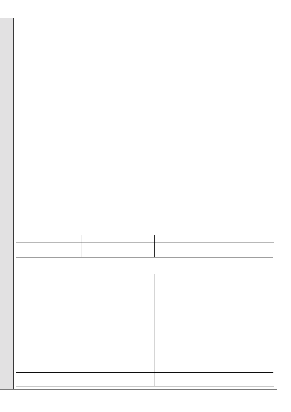
11
WALL MOUNTING TEMPLATE
1. Tape the template to the wall in the selected position.
Ensure squareness by use of a plumbline, as shown.
2. Mark out the position of the 3 wallplate screws, choosing
one from each group of 3 holes. Also mark the position of
the hole for the duct, the jacking screw and the top cover
plate screws.
3. Drill the 3 holes, 8 mm (
plugs. Drill the jacking screw and the top cover plate
screw holes 7mm (9/32") and insert the plastic plugs.
4. Remove the template from the wall.
12
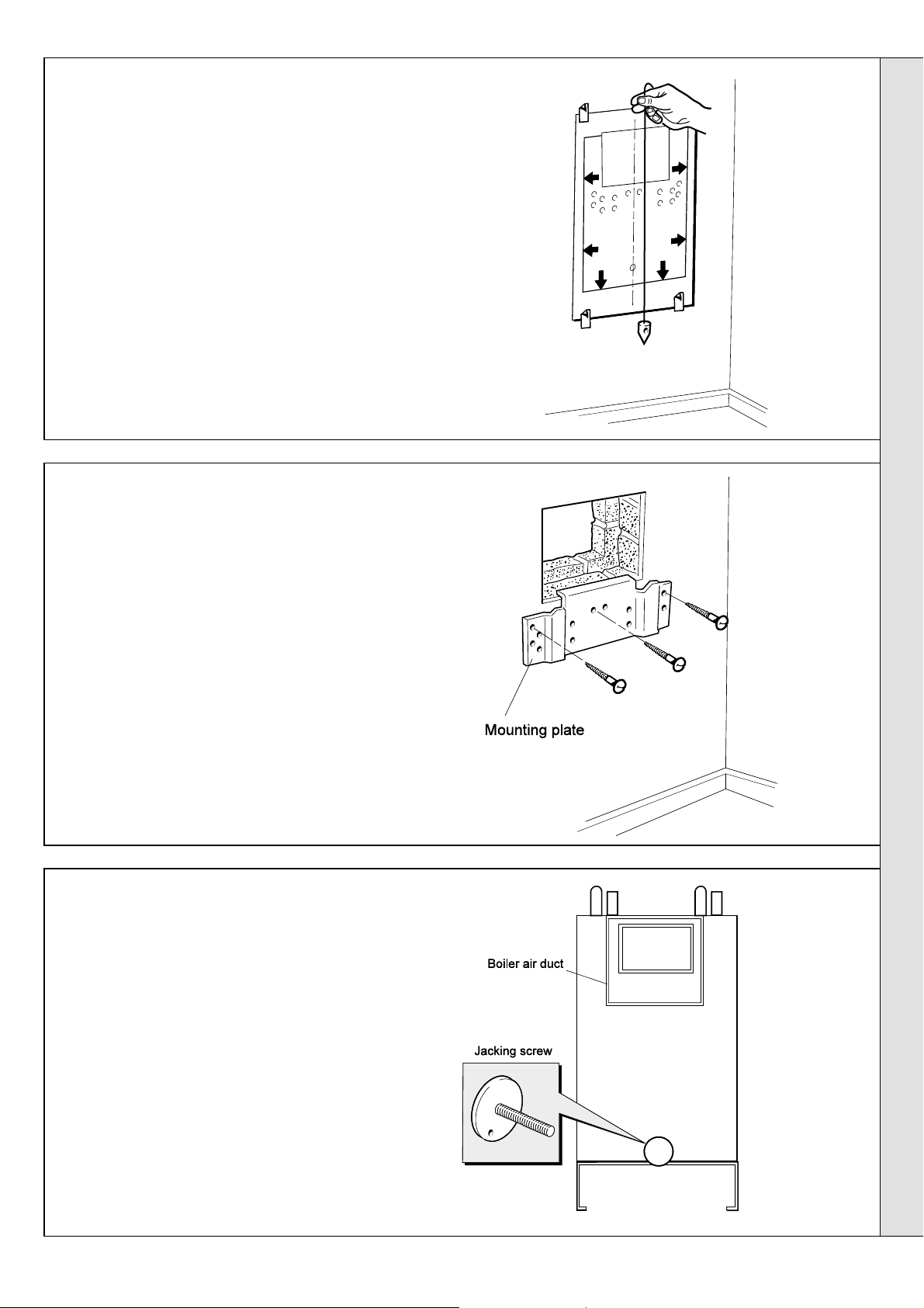
PREPARING THE WALL
5/16" ), and insert the 3 plastic
IMPORTANT.
The wall must be of suitable load bearing capacity.
1. Cut the appropriate hole in the wall for insertion
of the terminal assembly.
The terminal must not come into contact
Note.
with a combustible material such as that used
in the non-standard construction of timber
framework and plasterboard etc.
2. Fix the mounting plate to the wall with the 3
No.14 x 50 mm screws provided.
INSTALLATION
13
CHECKING THE BOILER
Check the jacking screw is fitted and screwed home.
Rear View of Boiler
Classic RS -
Installation & Servicing
13
Page 14

14
MOUNTING THE BOILER
INSTALLATION
Flue Alignment
1. Lift the boiler onto the wall mounting plate, entering the
projecting flue duct into the opening cut in the wall, and
lowering the 2 slots in the boiler back panel onto the angled
tabs on the top of the wall mounting plate.
DO NOT USE THE BURNER ASSEMBLY FOR LIFTING.
Top cover plate
LIFT HERE
Flue collector hood
LIFT HERE
INSTALLATION
Wall mounting plate
Boiler flue duct
Do NOT use the
burner assembly
for lifting
Clas 1999
LIFT HERE
It is
most
important
that the
boiler is
installed
in the
vertical
position
LIFT HERE
The wall must be of suitable load-bearing capacity
2. Adjust the flue to its horizontal
position by tilting the boiler forward at
the bottom then turning the jacking
screw. Release and check alignment
with a spirit level. Secure the jacking
screw with a No.10 x 50 mm wood
screw.
3. Fit the top cover plate in position
above the boiler air duct with the 2
No.10 x 50 mm screws provided.
15
FITTING THE FLUE ASSEMBLY
FLUE TERMINAL ASSEMBLY
Legend
1.Boiler air duct.
2.Boiler flue duct.
3.Terminal air duct.
4.Terminal flue duct.
1. Remove the 2 securing screws (6) and separate the
terminal grille (5), terminal flue duct (4) and terminal air
duct (3).
2. Smear sealant around outer the perimeter of the terminal
air duct at the opposite end to the brackets and on the
mating face of the boiler air duct (use one sachet of
sealant).
3. Push the terminal air duct fully in until the fixing brackets
contact the wall face.
5.Terminal grille.
6.Terminal grille securing screws
A. Air duct joint
B. Flue duct joint
FLUE TERMINAL SHOWN IN POSITION
4. Make good between the wall and duct, from OUTSIDE
of the building.
5. From OUTSIDE of the building, pass the terminal flue
duct through the wall opening and slide it over the boiler
flue duct. Locate it as shown.
6. Seal the flue duct joint (B) with the remaining sachet of
sealant provided.
7. Fasten the terminal grille to the flue and air ducts, using
6
the 2 securing screws (
) provided.
14
Classic RS -
Installation & Servicing
Page 15

16
GAS CONNECTION
INSTALLATION
17
WATER CONNECTIONS
A MINIMUM gas pressure of 20 mbar (8 in.w.g.) MUST be available at the boiler
inlet, with the boiler operating.
The main gas cock is on the left hand side of the gas control valve, as shown.
To facilitate connection the gas cock may removed from the gas control valve.
18
ELECTRICAL CONNECTIONS
WARNING.
The appliance must be efficiently earthed.
A mains supply of 230 V ~ 50 Hz is required.
All external controls and wiring must be suitable for mains voltage. Wiring
should be in 3-core PVC insulated & sheathed cable, not less than 0.75mm
2
(24 x 0.2mm) to BS. 6500 Table 16 Wiring Regulations and local regulations.
For IE reference should be made to the current ETCI rules for electrical
installations.
Connection must be made in a way that allows complete isolation of the
electrical supply - such as a double pole switch, having a 3mm (1/8") contact
separation in both poles or a plug and socket, serving only the boiler and
system controls. The means of isolation must be accessible to the user
after installation.
LEGEND
b blue
bk black
br brown
gy grey
or orange
pk pink
r red
v violet
w white
y/g yellow/green
Note.
the instructions provided with the kit and Frame 19.
Flow wiring diagram
Programmer unit
L
ALL EARTHS must be connected
(Not all earths are shown for clarity)
br
or
B
y
w
r
L
Off On Off On
8 Pin connector to
sytem controls
Connect
to
L
N
b
B
Control
thermostat
O/heat thermostat
(if fitted)
L
L
PCB 25
NC
C
NO
bk
bk
N
GV 1
bk
br
GV 2
Combined spark &
sending electrode
b
y/g
Pilot gas
b
Mains gas
Clas 2109
1. Remove the plastic plugs from the
flow and return pipes.
2. Make all water connections and check
for water soundness.
INSTALLATION
If an optional programmer is to be fitted refer to
1. Remove the control box securing screws (M4
pozi). Pull the box forward to disengage.
Refer to Frame 39.
2. Route the mains cable through the grommet
in the plate of the control box.
3. Remove the screw and release the mains
connection plate. Unscrew the cable clamp
screws and remove the clamp.
4. Connect the mains cable wires to the
terminal strip.
5. Replace the control box and fasten to the
controls support.
Optional Programmer Kit
19
EXTERNAL CONTROLS
External wiring must be in accordance with the current I.E.E.
(BS 7671) Wiring Regulations. For Ireland reference should be made
to the current ETCI rules for electrical installations.
The wiring diagrams illustrated in Frames 21-24 cover the systems
most likely to be fitted to this appliance.
For wiring external controls to the Classic RS boiler, reference should
be made to the system wiring diagrams supplied by the relevant
manufacturer, in conjunction with the wiring diagrams shown in Frames
21-24.
Difficulty in wiring should not arise, providing the following directions
are observed:
1. Controls that switch the system ON and OFF, e.g. a time switch,
MUST be wired, in series, in the live mains lead to the boiler.
2. Controls that override an ON/OFF control, e.g. a frost thermostat,
MUST be wired into the mains lead, in parallel, with the control(s)
to be overridden. Refer to Frame 24.
Classic RS -
Installation & Servicing
Boiler
For details of PCB wiring refer to Frame 20
3. Controls that switch the circulation pump only ON and OFF, e.g. a
room thermostat, MUST be wired in series with the pump in the live
pump lead.
4. If a proprietary system is used, follow the instructions supplied by
the manufacturer.
5. SYSTEM DESIGNS FEATURING CONTROLS OR WIRING
ARRANGEMENTS WHICH ALLOW THE BOILER TO FIRE WHEN THERE
IS NO PUMPED OR GRAVITY CIRCULATION TAKING PLACE SHOULD
NOT BE FITTED.
Advice on required modifications to the wiring may be obtained from the
component manufacturers.
Notes
1. Connections between a frost thermostat and the time
control should be made without disturbing other wiring.
2. A frost thermostat should be sited in a cool place in the house, but
where it can sense heat from the system.
15
Page 16

20
PICTORIAL WIRING
LEGEND
b blue
bk black
br brown
r red
y yellow
INSTALLATION
w white
or orange
v violet
p pink
gy grey
y/g yellow/green
Printed ciruit
board
Clas 2110
INSTALLATION
Ignition/
detection
electrode
y/g
bk
bk
y/g
gy
y/g
Gas valve
MAINS
b
br
y/g
r
b
br
bk
b
y/g
br
br
Overheat thermostat (if fitted)
21
MID POSITION VALVE
Pumped only
Notes.
1. Some earth wires are omitted for
clarity. Ensure proper earth
continuity when wiring.
2. Numbering of terminals on
thermostats is specific to the
manufacturer.
3. This is a fully controlled system - set
the boiler thermostat to maximum.
4. Switchmaster 'Midi' is similar in
operation but the wiring differs
slightly; see manufacturer's
literature.
LEGEND
b blue
bk black
br brown
r red
or orange
w white
gy grey
y/g yellow/green
16
Classic RS -
Installation & Servicing
Page 17

22
TWO SPRING CLOSED VALVES
Pumped only
Notes.
1. Some earth wires are omitted for clarity.
Ensure proper earth continuity when
wiring.
2. Numbering of terminals on thermostats is
specific to the manufacturer.
3. This is a fully controlled system - set the
boiler thermostat to maximum.
INSTALLATION
4. Switchmaster valve has grey and orange
auxiliary switch leads but the grey wire
must be connected to the live supply.
LEGEND
b blue
bk black
br brown
r red
w white
or orange
y/g yellow/green
gy grey
23
HONEYWELL 'C' PLAN
Gravity HW and Pumped CH
Notes.
INSTALLATION
1. Some earth wires are omitted for
clarity. Ensure proper earth continuity
when wiring
2. Numbering of terminals on
thermostats is specific to the
manufacturer.
LEGEND
w white
r red
bk black
br brown
or orange
b blue
gy grey
y/g yellow/green
Classic RS -
Installation & Servicing
17
Page 18

24
INSTALLATION
INSTALLATION
FROST PROTECTION
Central heating systems fitted wholly inside the house do not
normally require frost protection as the house acts as a 'storage
heater' and can normally be left at least 24 hrs. without frost
damage. However, if parts of the pipework run outside the house
or if the boiler will be left off for more than a day or so, then a frost
'stat should be wired into the system.
This is usually done at the programmer, in which case the
programme selector switches are set to 'Off' and all other controls
MUST be left in the running position. The frost 'stat should be
sited in a cold place but where it can sense heat from the system.
Wiring should be as shown, with minimal disturbance to other
wiring of the programmer.
25
COMMISSIONING AND TESTING
The Benchmark Log Book or equivalent self certification should be completed and signed to demonstrate compliance with
Building Regulations.
A. ELECTRICAL INSTALLATION
Designation of the terminals will vary, but the programmer and
thermostat manufacturer's leaflets will give full details.
Diagram A shows a double pole frost 'stat, which should suffice
for all systems which do not use the 'OFF' terminals of the
programmer.
Diagram B shows a 'change-over' frost 'stat, which will cover
most systems which do use 'CH OFF.' If, however, on such a
system the HW pipework is in an isolated part of the house, a
second frost 'stat may be used to protect it. If in doubt, ask
your installer for advice.
B. GAS INSTALLATION
1. Checks to ensure electrical safety should be
carried out by a competent person.
2. ALWAYS carry out preliminary electrical
system checks, i.e. earth continuity, polarity,
resistance to earth and short circuit ,using a
suitable test meter.
WARNING.
Whilst effecting the required gas soundness test and purging air from the gas installation,
open all windows and doors, extinguish naked lights and DO NOT SMOKE.
18
1. The whole of the gas installation, including the meter,
MUST be inspected and tested for soundness, and
purged in accordance with the recommendations of
BS. 6891. In IE refer to I.S.813:2002.
2. Purging air from the gas installation may be
expedited by loosening the union on the gas service
cock on the boiler and purging until gas is detected.
3. Retighten the union and check for gas soundness.
Classic RS -
Installation & Servicing
Page 19

26
INITIAL LIGHTING
INSTALLATION
AD
CL2111
B
1. Check that all drain cocks are CLOSED and any valves in
the flow and return lines are OPEN.
2. Check that the gas service cock (B) is OPEN and that the
boiler thermostat knob (D) is OFF.
Fit the boiler casing but do not fit the controls casing pod
(Frame 26).
C
0
1
6
5
2
4
3
F
E
G
LEGEND
A Sightglass
B Gas service cock
C Inlet pressure test point
D Thermostat knob
E Main burner pressure
adjuster
F Burner pressure test point
G Overheat stat reset button
8. Set the boiler thermostat knob (D) to maximum. The pilot
gas valve should open and pilot ignition commence. When
the pilot is alight the main burner will cross-light smoothly.
If the boiler does not light, refer to the Fault Finding section.
9. Test for gas soundness around ALL boiler gas components,
using leak detection fluid.
INSTALLATION
3. Fitting the Boiler Casing
The boiler casing must be refitted with the controls
support casing attached for alignment purposes. Check
that the sealing strip is in place along the 4 rear edges of
the boiler casing, locate over the upper support bracket
and secure with the 3 captive screws.
The casing must seat correctly and compress the sealing
strip to make an airtight joint.
Visually check the side seals but, if side clearances are
limited, then check that the top and bottom edges of the
casing are correctly located.
If the Sealed System Unit is fitted remove the unit casing
in order to inspect the top casing seal.
To gain access to the gas valve:
a. Remove the controls support casing. Release the
controls support front fixing screws 3 turns only.
Remove the pod by pulling it forward to disengage
from the keyhole slots.
b. Remove the control box securing screws and swing it
down into the servicing position
4. Slacken the screw in the burner pressure test point (F)
and connect a gas pressure gauge via a flexible tube.
5. Swing the control box back into its working position.
6. Switch the electricity supply ON and check that all
external controls are calling for heat.
7. Press the overheat thermostat reset button (G), if fitted.
10. Operate the boiler for 10 minutes to stabilise the burner
temperature.
11. The boiler is preset at the factory but if any adjustment is
necessary proceed as follows:
a. Set the boiler control knob to OFF.
b. Switch the electricity supply OFF.
c. Swing the control box down into the servicing position.
d. Remove the main burner adjuster cover.
e. Turn the adjusting screw
pressure, or
f. Swing the control box back into its working position.
g. Switch the electricity supply ON, the control knob ON and
check the new setting pressure.
12. If necessary repeat steps 11a to g until the required burner
pressure is achieved. Record this value in the Benchmark log
book.
13. Set the boiler control knob to OFF.
14. Switch the electricity supply OFF.
15. Swing the control box down into the servicing position.
16. Refit the main burner pressure adjuster cover.
17. Remove the pressure gauge and tube. Retighten the sealing
screw in the pressure test point. Ensure a gas tight seal is
made.
anticlockwise
clockwise
to DECREASE the pressure.
to INCREASE the
Classic RS -
Installation & Servicing
18. Swing the control box back into its working position and
secure.
19
Page 20
27
GENERAL CHECKS
INSTALLATION
Make the following checks for correct operation:
1. Set the boiler thermostat knob to position 6 and operate
the mains on/off switch. Check that the main burner lights
and extinguishes in response.
2. The correct operation of ANY programmer and all other
system controls should be proved.
Operate each control separately and check that the main
burner or circulating pump, as the case may be, responds.
3. Check that the casing is sealed correctly and compressing
the sealing strip all around the casing.
INSTALLATION
4. Water Circulating System
a. With the system HOT, examine all water connections for
soundness.
b. With the system still hot, turn off the gas, water and
electricity supplies to the boiler and drain down, in order
to complete the flushing process.
c. Refill and vent the system, clear all air locks and again
check for water soundness.
d. Balance the system.
The temperatures quoted below are approximate and vary
between installations.
Knob Setting Flow Temperature
°C °F
1 54 130
2 60 140
3 66 150
4 71 160
5 77 170
6 82 180
WARNING.
The boiler MUST NOT
be operated with the casing removed.
5. Finally, set the controls to the user's requirements.
28
HANDING OVER
After completing the installation and commissioning of the system the
installer should hand over to the householder by the following actions:
1. Hand the User's Instructions to the householder and
explain his or her responsibilities under current Gas
Safety (Installation and Use) Regulations or rules in
force.
2. Draw attention to the lighting instruction label affixed to
the controls pod door.
3. Explain and demonstrate the lighting and shutting down
procedures.
4. The operation of the boiler and the use and adjustment
of ALL system controls should be fully explained to the
Householder, to ensure the greatest possible fuel
economy consistent with household requirements of
both heating and hot water consumption.
Advise the User of the precautions necessary to
prevent damage to the system and to the building, in
the event of the system remaining inoperative during
frosty conditions.
5. Explain the function and the use of the boiler
thermostat and external controls.
6. Explain the function of the boiler overheat thermostat (if
fitted) and emphasise that if cutout persists, the boiler
should be turned off and a CORGI registered installer
consulted. In IE contact a Competent Person.
7. Explain and demonstrate the function of time and
temperature controls, radiator valves etc., for the
economic use of the system.
8. If any programmer is fitted, draw attention to the
Programmer User's Instructions and hand them to the
Householder.
9. After installation, commissioning and customer
handover, please complete the appliance
log book and leave this with the customer. For IE, it is
necessary to complete a "Declaration of Conformity" to
indicate compliance to I.S. 813:2002.
10.Stress the importance of regular servicing by a CORGI
registered installer and that a comprehensive service
should be carried out AT LEAST ONCE A YEAR. In IE
servicing work must be carried out by a Competent Person.
20
Classic RS -
Installation & Servicing
Page 21

SERVICING
29
SCHEDULE
To ensure the continued safe and efficient operation of the
appliance it is recommended that it is checked at regular intervals
and serviced as necessary. The frequency of servicing will
depend upon the installation condition and usage but should
be carried out at least annually .
It is the law that any service work must be carried out by a
CORGI registered installer. In IE service work must be carried
out by a Competent Person.
a. Light the boiler and carry out a pre-service check, noting
any operational faults.
b. Clean the main burner.
c. Clean the heat exchanger.
d. Clean the main and pilot injectors.
e. Remove any debris from inside the base of the casing.
30
BOILER CASING REMOVAL
1. If the Classic Sealed System Unit is fitted lift off the
casing to expose the boiler casing top fixing screw.
2. Open the controls pod door and release the 3 captive
screws at the top and bottom of the casing. Lift the
casing off the boiler and retain in a safe place.
3. Release the 3 captive screws at the top and bottom of
the casing. Lift the casing off the boiler and retain in a
safe place .
4. Isolate the gas supply at the service cock.
f. Check that the flue terminal is unobstructed and that the
flue system is sealed correctly.
g. If the appliance has been installed in a compartment, check
that the ventilation areas are clear.
The servicing procedures are covered more fully in Frames 30
to 35 and MUST be carried out in sequence.
WARNING.
IMPORTANT. After completing the servicing or exchange of
components always test for gas soundness and carry out
functional checks as appropriate.
When work is complete the casing MUST be correctly refitted,
ensuring that a good seal is made.
The boiler must NOT be operated if the casing is not fitted.
Note.
components, the boiler casing must be removed (Frame 30).
Disconnect the electrical supply.
In order to carry out either servicing or replacement of
1 captive screw
2 captive screws
31
BURNER AND AIR BOX REMOVAL
1. Remove the screw retaining the burner support
bracket to the combustion chamber.
2. Remove the M5 pozi screw situated at the LH
bottom rear of the burner and pull the burner
downward in order to disengage the retention tab.
Remove burner to a safe place for inspection and
cleaning.
3. Remove the 4 screws retaining the air box / pilot
assembly to the vertical manifold.
4. Remove the control box fixing screws and pull the
box forward and downward to disengage.
5. Pull off the electrode lead at the PCB.
6. Open the clips retaining the HT lead. Remove the
air box assembly to a safe place for inspection and
cleaning.
Main burner
injector
Electrode
Air box
M5 pozi screw
Cla 2112
Control
pod door
Detail of
location
tab
Main
burner
Clas 6033
SERVICING
Classic RS -
Installation & Servicing
21
Page 22
SERVICING
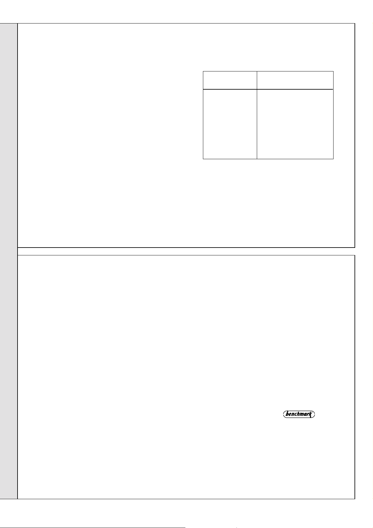
32
CLEANING THE FLUEWAYS
1. Remove the collector hood by undoing the front tie rod
nuts and releasing the tie rods from the combustion
chamber. Withdraw the rods.
2. Remove the 4 collector hood retaining screws and
washers.
33
CLEANING THE BURNER AND PILOT
ASSEMBLY
1. Brush off any deposits that may have fallen on to the
burner head (ensuring the flame ports are unobstructed)
and remove any debris that may have collected.
Note.
Brushes with metallic bristles must not be used.
2. Remove the main burner injector and ensure there is no
blockage or damage. Clean or renew as necessary.
3. Refit the injector, using an approved jointing compound
sparingly.
4. Inspect the pilot burner and ignition / detection electrode.
Ensure that they are clean and in good condition.
Check that:
a. The pilot burner injector is not blocked or damaged. Refer
to Frame 40 for removal details.
b. The pilot burner is clean and unobstructed.
c. The ignition / detection electrode is clean and
undamaged.
3. Uncouple and remove the flue baffles from the heat
exchanger.
4. Remove all loose deposits from the heat exchanger,
particularly between the fins, using a suitable brush.
34
REASSEMBLY
Reassemble in reverse order to that shown in Frames 30 to 33.
SERVICING
1. Refit the flue baffles and retain with the spring clips.
2. Refit the collector hood, replacing any damaged or
deteriorating gaskets.
Ensure that the rear vertical hood retaining
Note.
screws are tightened BEFORE the rear horizontal
screws and that the tie rods are located into the holes in
the base of the combustion chamber.
3. Refit the burner and air box assembly. Ensure the burner
tab is correctly located. Refer to Frame 43.
4. Refit the burner support.
d. The ignition / detection lead is in good condition.
e. The spark gap is correct . Refer to Frame 40. Clean or
renew as necessary.
The pilot shield is located around the pilot assembly
Note.
bracket and is located by the electrode retaining nut.
5. Refit the control box assembly.
6. Turn on the gas supply.
7. Ensure the sightglass in the boiler casing is clean and
undamaged .
8. Refit the boiler casing and tighten the 3 captive screws.
Close the pod door.
9. Inspect the visible casing seal for correct fit.
10. Close the controls pod door.
35
GAS PRESSURE ADJUSTMENT
PILOT
The pilot is factory set to maximum and no further
adjustment is possible. If, after removing and checking
the injector (as detailed in Frame 43) and ensuring that
there is an inlet pressure of 20 mbar available, the pilot
does not light then contact Caradon Ideal Limited.
Relight in accordance with 'Initial Lighting', Frame 26.
22
MAIN BURNER
After any servicing, reference should be made to Table 2,
which quotes details of the rated output with the related
burner setting pressure and the heat input. Any required
adjustments should be made by using the pressure
adjustment screw.
Refer to Initial Lighting, Frame 26.
Classic RS -
Installation & Servicing
Page 23

36
GENERAL
When replacing any component:
1. Isolate the electricity supply.
2. Turn off the gas supply at the boiler.
SERVICING
REPLACEMENT OF PARTS
Note.
In order to assist fault finding, the control box printed
circuit board is fitted with 2 indicator lights which represent the
following boiler conditions:
Neon I3. Mains electricity ON.
3. Remove the boiler casing . Refer to Frame 30.
IMPORTANT. When work is complete the casing MUST be
correctly refitted - ensuring that a good seal is made.
37
SIGHTGLASS REPLACEMENT
1. Refer to Frame 36.
2. Unfasten the 2 nuts and washers holding the
sightglass assembly to the casing front panel.
3. When fixing the new assembly, ensure that the
parts are in the correct order. The frame MUST
have the return edge at the bottom.
4. Retighten the 2 nuts to ensure an airtight
seal. Do NOT overtighten.
5. Replace the boiler casing. Refer to Frame 26.
38
OVERHEAT THERMOSTAT REPLACEMENT (if fitted)
Neon SG1. Flashes to indicate ignition operation (stops after
detection).
The boiler MUST NOT be operated if the casing is not fitted.
SERVICING
1. Refer to Frames 36 & 52.
2. Remove the control box securing screws.
3. Pull the box forward and downward to disengage
CL 2113
4. To remove the overheat thermostat, pull off the electrical
connections at the thermostat. Remove the backnut retaining
the thermostat to the bracket. Remove the thermostat from the
heat exchanger pocket.
5. Fit the new thermostat and reassemble in reverse order.
6. Check the operation of the boiler.
Classic RS -
Installation & Servicing
23
Page 24

39
Cla 2118
2
CONTROL THERMOSTATREPLACEMENT
1. Refer to Frame 36.
2. Pull the knob off the shaft.
3. Remove the control box fixing screws.
Pull the box forward and downward to
disengage.
4. Remove the screws securing the
thermostat control to the control box.
5. Remove the phial from the pocket.
6. Replace and reassemble in reverse
order.
3
SERVICING
CL 2119
3
4
40
SERVICING
Cla 2117
6
Cla2120
PILOT BURNER REPLACEMENT
1. Refer to Frame 36.
2. Remove the burner and air box assembly. Refer to Frame
43.
3. Remove the electrode retaining nut and remove the pilot
shield and electrode.
4. Unscrew the central pilot fixing screw and lift the pilot
burner? clear of the pilot injector. If required, the pilot
injector may now be unscrewed.
5. Replace the pilot burner (and injector if necessary) and
retain with the M4 screw previously removed. Ensure that
the copper sealing washer is replaced when refitting the
pilot injector.
24
6. Replace the electrode and pilot shield - retaining both
with the electrode nut. Check the spark gap.
7. Replace the airbox assembly .
8. Replace the burner.
9. Replace the boiler casing.
10. The pilot is factory set to maximum and no further
adjustment is possible. Ensure that there is an inlet
pressure of 20 mbar available. Also check burner
ignition and cross-lighting.
Classic RS -
Installation & Servicing
Page 25

SERVICING
41
IGNITION ELECTRODE AND LEAD REPLACEMENT
1. Refer to Frame 36.
2. Remove the burner and air box assembly. Refer to Frame 43.
3. Remove the electrode retaining nut.
4. Remove the pilot shield.
5. Remove the ignition electrode and integral lead.
6. Refit the new electrode and lead in reverse order.
Ensure that the pilot shield is replaced.
7. Check the spark gap. Refer to Frame 40.
8. Refit the burner.
9. Check the pilot ignition.
42
DETECTION ELECTRODE REPLACEMENT
1. Refer to Frame 36.
2. Pull the electrode and lead from the PCB connection.
3. Remove the bracket retaining screw.
4. Pull the bracket forward to disengage the rear retaining
clip.
5. Remove the bracket.
6. Remove the screw retaining
the detection electrode.
7. Fit new detection electrode
and reassemble in reverse
order.
3
4
2
Clas 2122
Retaining
clip
Cla 2121
43
MAIN BURNER AND MAIN BURNER INJECTOR REPLACEMENT
1. Refer to Frame 36.
2. Remove the screw retaining the front burner support strap
to the combustion chamber.
3. Remove the M5 pozi screw, situated at the LH bottom rear
of the burner. Pull the burner downward to disengage the
retention tab and remove the burner.
4. At this stage the main burner injector can be removed,
checked, cleaned or replaced as required. Ensure that an
approved jointing compound is used sparingly.
5. Fit the new burner, ensuring that the retention tab is
correctly located in the air box slot.
6. Refit the M5 retaining screw.
7. Refit the boiler casing.
9. Check the burner for cross-lighting and flame stability.
SERVICING
Classic RS -
Installation & Servicing
25
Page 26

SERVICING
cla 6034
Gas cock union
Gas cock
6
44
GAS CONTROL VALVE REPLACEMENT
Note.
Refer also to Frame 53 of 'Exploded Views' for
illustration of the procedure detailed below.
1. Refer to Frame 36.
2. Remove the burner and air box assembly. Refer to Frame 43.
3. Remove the control box securing screws. Pull the box forward
and downward to disengage.
4. Remove the gas control valve electrical connection.
5. Disconnect and remove the gas union from the gas control
valve.
6. Whilst supporting the gas control valve, remove the 2
screws retaining the manifold to the back panel.
7. Remove the gas control / manifold assembly.
8. Remove the 4 screws retaining the manifold to the gas control
valve and fit the new manifold to the gas control valve, ensuring
that it is fitted the correct way round (an arrow engraved on the
back indicates the direction of flow).
Remove the gas cock stub and refit into the new gas
Note.
control valve. Use an approved jointing compound on the pipe
stub.
9. Reassemble in reverse order.
10. Replace the boiler casing.
11. Check the gas valve operation.
45
Note.
illustration of the procedure detailed below.
SERVICING
1. Refer to Frame 36.
2. Remove the control box fixing screws. Pull the box
forward and downward to disengage.
3. Remove the HT lead from the PCB.
46
1. Refer to Frame 36.
2. Remove the burner and air box
assembly. Refer to Frame 43.
3. Remove the 4 tie rods.
4. Remove the combustion chamber.
5. Remove the 2 side panel retaining
brackets.
6. Remove the side insulation panels.
PRINTED CIRCUIT BOARD (PCB) REPLACEMENT
Refer to Frame 52 of 'Exploded Views' for
4. Transfer,
connectors to the new PCB.
5. Compress the barbs on the PCB stand-offs to release the
PCB from the box.
6. Fit the new PCB and reassemble in reverse order.
7. Refit the boiler casing.
8. Check the operation of the boiler.
one by one
COMBUSTION CHAMBER INSULATION REPLACEMENT
7. Remove the front and rear
insulation panels.
8. Fit the new front and rear
insulation panels.
9. Fit the new side panels and
retain with the brackets and
screws previously removed.
10. Reassemble in reverse order.
(to avoid confusion), all push-in
26
Classic RS -
Installation & Servicing
Page 27

47
HEAT EXCHANGER REPLACEMENT
Note.
Refer to Frame 3 (Boiler Assembly - Exploded
view) for illustration of the procedure detailed below.
SERVICING
7. Remove the thermostat sensors from the pockets on the
heat exchanger by removing the M3 screws and plates.
8. Slacken 3 turns only the 4 heat exchanger / inter-panel
retaining screws.
1. Refer to Frame 36.
2. Remove the burner / air box assembly. Refer to Frame
43.
3. Drain the system.
4. Disconnect the water connections. If compression
fittings are used then cut the pipes both above and
below the fittings in order to allow the heat exchanger
assembly to be removed. Remove the heat exchanger
drain plug and drain the residual water into a suitable
receptacle.
5. Remove the collector hood assembly. Refer to Frame 3
6. Remove the combustion chamber by unscrewing the 4
tie rods and removing the detection electrode. Refer to
Frame 42.
48
CASING SEAL REPLACEMENT
1. Refer to Frame 36.
2. Remove the old seal from the casing surround
and thoroughly clean the casing surfaces
9. Lift the heat exchanger / inter-panel assembly upward and
forward to disengage key hole fixings. Pull the assembly
downward to clear the water pipes from the back panel.
10. Remove the 2 rubber sealing grommets from the top of the
back panel to facilitate fitting the new assembly.
11. Fit the new heat exchanger assembly, complete with water
pipes, and hang it on the key hole slots and screws.
Retighten the screws.
12. Replace the 2 rubber sealing grommets.
13. Reassemble in reverse order.
14. Remake all water connections, ensuring that the
compression fittings (if used) are correctly refitted.
15. Fully test all functions, including water and gas soundness.
Seal
3. Fit the new adhesive seals.
4. Replace the boiler casing.
49
PROGRAMMER REPLACEMENT (if fitted)
1. Refer to Frame 36.
2. Remove the fixing screws and swing
the control box down into the
servicing position.
3. Pull off the terminal connections from
back of the programmer.
4. Compress the lugs at each side of
the programmer and withdraw it from
the control panel.
5. Fit the new programmer in reverse
order.
Programmer
SERVICING
cla 6036
Cla 2163
6. Set the programmer to the desired
programme and check the operation
of the boiler.
Classic RS -
Installation & Servicing
27
Page 28

FAULT FINDING
START
Check that the Mains On
neon 'I3' is illuminated.
YES
Is there a live supply to both
terminals of overheat 'stat?
YES
Check that the boiler
thermostat is set at maximum.
Is the ignition electrode
sparking ?
NO
NO
NO
Check mains supply and fuses.
Check programmer and system
thermostats are all ON.
Check mains input is sound.
Can the overheat 'stat be reset
when the system is cold ?
Has the fuse blown on PCB ?
NO
YES
NO
YES
Reset the overheat 'stat. Set control
'stat to maximum. Allow the boiler to
reach temperature - if the overheat
'stat trips again, measure flow
temperature.
If above 90°C replace control 'stat.
If below 90°C replace overheat 'stat.
Replace the overheat thermostat
Replace fuse BUT, before
attempting to start boiler, check for
short between live and neutral,
also between live and earth, on all
items plugged into the PCB.
YES
Does the pilot light ?
NO
Is there a gas supply
to the boiler?
YES
Has the gas line been
purged of air ?
YES
Is the pilot injector
blocked?
NO
YES
Is there a regular spark from
tube 'SG1' on the PCB?
Does the spark stop
after pilot is lit?
NO
Check the polarity of
the mains supply.
Check the continuity of
the ignition lead from
connector to electrode.
Does the spark now
cease when gas is lit ?
NO
YES
YES
Check gap at ignition electrode.
Check electrode and lead are
undamaged, and not close to
earthed metalwork.
NO
Check all connections to PCB.
If no fault found change PCB.
Does main burner cross-light from pilot?
NO
Is there a supply on terminals of
main gas valve?
NO
Is the main burner
injector clear?
YES
YES
Ensure pilot and
main gas valve leads
are not crossed over.
Is there a supply
FAULT FINDING FAULT FINDING FAULT FINDING FAULT FINDING FAULT FINDING FAULT FINDING
voltage at pilot gas
28
valve?
NO
YES
Check all connections to PCB.
If no fault found, replace PCB.
Replace gas valve
Replace main gas
solenoid valve
Classic RS -
Installation & Servicing
Page 29

SHORT LIST OF PARTS
The following list is comprised of parts commonly required as
replacement components, due to damage or expendability. Their failure
or absence is likely to affect safety or performance.
The list is extracted from the British Gas List of Parts, which contains all
available spare parts.
The full list is held by British Gas, Caradon Ideal Limited distributors
and merchants.
When replacing any part on this appliance, use only spare parts that you can be assured conform to the safety and performance
specification that we require. Do not use reconditioned or copy parts that have not been clearly authorised by Ideal Boilers.
Key No. G.C. Part No. Description Qty. Product No.
9 308 365 Sightglass assembly kit. 1 171 414
12 Main burner RS 330 & RS 340 1 171 013
Main burner RS 350 & RS 360 1 171 416
13 Main burner injector RS 330 & RS 340 1 171 425
Main burner injector RS 350 1 171 426
Main burner injector RS 360 1 171 427
When ordering please quote:
1. Boiler model
2. Appliance G.C. number
3. Description
4. Quantity
5. Product no.
14 397 943 Pilot burner injector 1 171 434
15 308 358 Pilot burner head with injector 1 171 438
17 Gas valve kit 1 171 441
18 308 317 Ignition/detection electrode, complete with lead and
backnut 410mm lg. 1 171 442
18.1 Detection electrode 1 171 973
19 Control box assembly & PCB 1 171 927
23 Automatic ignition PCB 1 171 928
25 386 139 Boiler thermostat 1 171 970
26 308 283 Thermostat knob 1 171 929
35 308 523 Boiler casing assembly, complete with sightglass
assembly, insulation and M5 x 16 dogpoint pozpan hd. 1
37 308 541 Controls casing door with Lighting Instructions 1 171 978
39 308 329 Casing sealing pack, complete with screws 1 171 479
45 386 144 Overheat thermostat 1 171 950
Classic RS -
Installation & Servicing
29
Page 30

50
SHORT PARTS
SHORT LIST OF PARTS
9
17
25
12
18
26
18.1
13 14
19
23
39 45
15
Cla 2124
51
BOILER CASING ASSEMBLY
35
30
37
Classic RS -
Installation & Servicing
Page 31

52
CONTROL BOX - Exploded View
SHORT LIST OF PARTS
LEGEND
19. Control box
25.Boiler thermostat
23. Printed circuit board
26. Thermostat knob
23
25
19
26
Optional Extra
53
BURNER ASSEMBLY - Exploded view
Clas 2123
LEGEND
10. Burner manifold
11. Air box and pilot assembly.
12. Main burner.
Classic RS -
Installation & Servicing
13. Main burner injector.
16. Pilot shield.
17. Gas control valve.
42. Gas service cock.
31
Page 32

The code of practice for the installation,
commissioning & servicing of central heating systems
THIS SYMBOL IS YOUR
ASSURANCE OF QUALITY
These appliances are designed for use with Natural
Gas only. They have been tested and conform with the
provisions of BS. 6332 and BS. 5258.
Technical Training
The Ideal Boilers Technical Training Centre offers a series of
first class training courses for domestic, commercial and
industrial heating installers, engineers and system specifiers.
For details of courses please ring: .............. 01482 498 432
CERTIFIED PRODUCT
Manufactured under a BS EN ISO 9001: 1994
Quality System accepted by BSI
Ideal Boilers,
HU5 4JN. Telephone: 01482 492 251 Fax: 01482 448 858.
Registration No. London 322 137.
Caradon Ideal Limited pursues a policy of continuing
improvement in the design and performance of its products. The
right is therefore reserved to vary specification without notice.
P.O. Box 103, National Ave, Kingston upon Hull,
Ideal Installer/Technical Helpline: 01482 498663
www.idealboilers.com
February 2003 UIN 157 757 A04
 Loading...