

Page 1

Classic Combi FF 280
Installation & Servicing
Wall Mounted, Fanned, Balanced Flue Gas Boilers
Natural Gas Models Only
Classic Combi G.C. Appliance No.
FF 280 .............................47 415 08
CAUTION.
To avoid the possibility of injury during the installation and servicing of this appliance, care should be taken when handling edges of sheet components.
NOTE TO THE INSTALLER: LEAVE THESE INSTRUCTIONS ADJACENT TO THE GAS METER
Page 2

GENERAL
CONTENTS
INTRODUCTION
The new Classic Combi FF280 is a cast iron, balanced flue,
fanned gas boiler.
Air Supply ..................................................................... 7
Boiler Clearances ......................................................... 6
Boiler Exploded View ................................................. 46
Burner Exploded View .............................................. .47
Control Box Exploded View ..................................... .47
Electrical Connections .............................................. 25
Electrical Regulations ................................................. 8
Extension Ducts - Fitting ........................................... 21
External Control ......................................................... 27
Fault Finding .............................................................. 48
Flueing .......................................................................... 7
Rear Installation ...................................................... 13
Side Installation ...................................................... 17
Gas Safety (Installation & Use)
Regulations, 1994 ........................................................ 5
Gas Supply ................................................................... 5
Health & Safety Document No 635 ............................. 5
Central heating (CH) output is spot rated at 23.4 kW (80 000
Btu/h) with on/off thermostatic control and is suitable for use with
heating loads down to 4.4 kW (15 000 Btu/h).
Maximum instantaneous domestic hot water (DHW) output is
also 23.4kW (80 000 Btu/h).
The boiler is designed for use with fully pumped sealed water
systems but can also be connected to open water systems if
required.
The boiler casing is of white enamelled mild steel with a
removable controls pod. A drop-down door gives access to the
control box.
Note. This boiler can only be used on fully pumped systems.
The boiler is supplied fully assembled, with a domestic hot water
calorifier, diverter valve, circulating pump, pressure gauge,
safety valve and CH expansion vessel (contained in a module
on top of the boiler).
Fixed temperature CH and DHW controls are fitted and the
boiler incorporates a DHW 'preheat' facility.
The module also includes a CH thermostatic valve and bypass.
No external bypass is required.
The domestic hot water and central heating pipe connections
may be made at the top or bottom of the boiler as required.
The boiler is supplied with a standard flue kit suitable for rear or
side outlet applications up to 600mm (23
extension ducts up to 3m (118"), rear or side outlet, are
available.
Note. A Vertex Flue Kit with a side outlet may be used - see the
Vertex Flue Kit Installation Instructions for details.
1/2"). Optional extra
Initial Lighting . .......................................................... 29
Installation .................................................................. 11
Mandatory Requirements ............................................ 5
Pump ........................................................................... 24
Servicing ..................................................................... 32
Short List of Parts ...................................................... 54
Spares Replacement .................................................. 35
Terminal Guards. .......................................................... 7
Thermostatic Radiator Valves. .................................... 8
Water Circuit Diagrams ............................................... 4
Water Connections .................................................... 24
Water Requirements .................................................... 7
OPERATION
Domestic Hot Water (DHW)
With no call for either DHW or CH the boiler will periodically fire
at low gas rate for a few seconds, in order to maintain the DHW
calorifier in a preheated condition.
Note. The DHW 'preheat' operates 24 hours a day unless an
external programmer is fitted, when it can be timed.
When there is demand for DHW the boiler fires at full gas rate,
the diverter valve remains de-energised and the full output from
the boiler is directed to the DHW calorifier, providing a maximum
DHW draw-off of 9.6 l/m (2.1 gpm) at 35° C. temperature rise.
At DHW draw-off rates below approximately 6 l/m (1.3 gpm) the
boiler reduces to low gas rate when the DHW temperature
reaches about 60°C and maintains the low draw-off
temperature between 50°C and 75°C. When the demand for
DHW is satisfied the 'preheat' cycle resumes, unless there is a
CH demand, which takes priority.
Central Heating (CH)
When there is demand for CH, the boiler fires at full output, to
supply the demand. The CH circuit within the module
incorporates a thermostatic valve which operates to maintain a
high boiler temperature during periods of cold CH start-up,
necessary for the instantaneous delivery of DHW , if there is a
demand at this time. Water is not released to the system until a
temperature of 60°C. is reached within the boiler.
Refer also to 'Boiler Water Circuit Diagrams'.
2
Classic Combi FF 280 - Installation
Page 3

GENERAL
Table 1 - General Data
Boiler size FF 280
Gas supply connection Rc
Inlet connection Domestic Hot Water 15mm compression union
Outlet connection Domestic Hot Water 15mm compression union
Flow connection Central Heating 22mm compression union
Return connection Central Heating 22mm compression union
Safety valve drain pipe connection 15mm copper (female)
Flue terminal diameter mm (in.) 100 (4)
Maximum working pressure (sealed systems) bar (psi) 2.5 (36.3)
Maximum static water head m (ft.) 25 (82)
Minimum static water head - open water systems m (ft.) 1.5 (5.0)
Maximum domestic hot water inlet pressure bar (psi) 10.0 (145.0)
Minimum domestic hot water inlet pressure bar (psi) 0.9 (13.1)
Electrical supply 230 V ~ 50 Hz
Maximum power consumption 160W
Fuse rating External; 3A Internal; 2A (F)
Water content Central Heating litre (gal.) 4.65 (1.0)
Domestic Hot Water litre (gal.) 0.55 (0.12)
Dry weight (total) kg (lb) 78.7 (173)
Maximum installation weight kg (lb) Combi module - 11.4 (25.1)
Boiler casing size Height mm (in.) 1045 (41
Width mm (in.) 380 (15.0)
Depth mm (in.) Top water connections - 300 (11 3/4)
Bottom water connections - 345 (13 1/2)
1/2 (1/2" BSP/t )
Boiler module - 52.6 (116)
1/4)
Table 2 - Performance Data - Central Heating
Central Heating Maximum
Burner setting pressure (hot) mbar (in.w.g.) 16.0 (6.4)
Output kW (Btu/h) 23.4 (80 000)
Input kW (Btu/h) 29.3 (100 000)
3
Gas consumption (hot) l/s (ft
/h) 0.76 (96.3)
Table 3 - Performance Data - Domestic Hot Water
Domestic Hot Water Maximum
Burner setting pressure (hot) mbar (in.w.g.) 16.0 (6.4)
DHW output kW (Btu/h) 23.4 (80 000)
DHW input kW (Btu/h) 29.3 (100 000)
3
Gas consumption (hot) l/s (ft
/h) 0.76 (96.3)
Domestic hot water flow rate at 35°C. temp. rise l/m (gpm) 9.6 (2.1)
Note. Gas consumption is calculated using a calorific value of 38.7 MJ/m3 (1038 Btu/ft3)
Classic Combi FF 280 - Installation
3
Page 4

GENERAL
1
BOILER WATER CIRCUIT DIAGRAMS
4
Classic Combi FF 280 - Installation
Page 5

GENERAL
OPTIONAL EXTRA KITS
A Programmer Kit
A 90° Flue Elbow Kit
Extension ducts up to 3 m (118").
GAS SAFETY (INSTALLATION AND USE)
REGULATIONS, 1994.
It is law that all gas appliances are installed by a CORGI
registered installer (identified by
above regulations. Failure to install appliances correctly could
lead to prosecution. It is in your own interest, and that of safety,
to ensure the law is complied with.
The installation of the boiler MUST also be in accordance with
the latest I.E.E Wiring Regulations, local building regulations,
bylaws of the local water authority, the Building Regulations and
Building Standards (Scotland) and any relevant requirements of
the local authority.
Detailed recommendations are contained in the following British
Standard Codes of Practice:
BS.6891 Low pressure installation pipes.
) in accordance with the
The boiler may be fitted on a combustible wall. Insulation
between the wall and the boiler is not necessary, unless required
by the local authority. The boiler must not be fitted outside.
Timber Framed Buildings
If the boiler is to be fitted in a timber framed building it should be
fitted in accordance with the British Gas publication 'Guide for
Gas Installations in Timber Frame Housing', reference DM2.
Bathrooms
The boiler may be installed in any room or internal space,
although particular attention is drawn to the requirements of the
current I.E.E. (BS. 7671) Wiring Regulations and, in Scotland,
the electrical provisions of the building regulations applicable in
Scotland with respect to the installation of the boiler in a room or
internal space containing a bath or shower.
Where a room-sealed appliance is installed in a room containing
a bath or shower then the appliance and any electrical switch or
appliance control utilising mains electricity should be so situated
that it cannot be touched by a person using the bath or shower.
Where installation will be in an unusual location special
procedures may be necessary and BS.6798 gives detailed
guidance on this aspect.
BS.6798 Installation of gas fired hot water boilers of rated
input not exceeding 60 kW.
BS.5449 Forced circulation hot water systems.
BS.5546 Installation of gas hot water supplies for domestic
purposes (2nd Family Gases).
BS.5440:1 Flues for gas appliances of rated input not
exceeding 60 kW.
BS.5440:2 Ventilation for gas appliances of rated input not
exceeding 60 kW.
BS.7593:1992 Treatment of water in domestic hot water central
heating systems
HEALTH & SAFETY DOCUMENT NO 635
The Electricity at Work Regulations, 1989.
Manufacturer’s notes must NOT be taken in any way as
overriding statutory obligations.
IMPORTANT.
This appliance is certificated by the British Standards Institution
for safety and performance. It is, therefore, important that no
external control devices, e.g. flue dampers, economisers etc.,
are directly connected to this appliance - unless covered by
these Installation and Servicing Instructions or otherwise
recommended by Caradon Ideal Ltd. in writing.
If in doubt please enquire.
Any direct connection of a control device not approved by
Caradon Ideal Ltd., could invalidate the BSI Certification and
the normal appliance warranty. It could also infringe the Gas
Safety Regulations and the above regulations.
Compartment Installations
A compartment used to enclose the boiler should be designed
and constructed specially for this purpose.
An existing cupboard or compartment may be used, provided
that it is modified for the purpose.
In both cases details of essential features of cupboard /
compartment design, including airing cupboard installation, are
to conform to the following:
z BS. 6798.
z The position selected for installation MUST allow adequate
space for servicing in front of the boiler and for air
circulation around the boiler - see section on 'Air Supply'.
z For the minimum clearances required for safety and
subsequent service see the wall mounting template and
Frame 2. In addition, sufficient space may be required to
allow lifting access to the wall mounting plate.
GAS SUPPLY
The local gas supplier should be consulted, at the installation
planning stage, in order to establish the availability of an
adequate supply of gas. An existing service pipe must NOT be
used without prior consultation with the local gas supplier.
A gas meter can only be connected by the local gas supplier or
by a local regional contractor.
An existing meter should be checked, preferably by the gas
supplier, to ensure that the meter is adequate to deal with the
rate of gas supply required. A MINIMUM pressure of 20mbar
MUST be available at the boiler inlet, with the boiler operating.
LOCATION OF BOILER
The boiler must be installed on a flat and vertical wall, capable of
adequately supporting the weight of the boiler and any ancillary
equipment.
Classic Combi FF 280 - Installation
Installation pipes MUST be fitted in accordance with BS. 6891.
Pipework from the meter to the boiler MUST be of an adequate
size.
The complete installation MUST be tested for gas soundness
and purged as described in the above code.
5
Page 6

GENERAL
2
BOILER DIMENSIONS / SERVICES
LEGEND
1. DHW inlet
2. DHW outlet
3. Safety valve drain
4. CH return
5. CH flow
BOILER CLEARANCES
The following minimum clearances must be maintained for
operation and servicing (see diagram).
Additional space will
be required for
installation,
depending upon site
conditions.
Side Flue only
Provided that the flue
hole is cut accurately,
e.g. with a core drill,
the flue can be installed from inside the building, up to 610mm
(24") but, with flue lengths greater than the width of the boiler, the
space in which the boiler is to be installed must be at least equal
to the flue length plus the length of the terminal grille.
Installation from inside
ONLY
If a core boring tool is to be
used inside the building the
space in which the boiler is
to be installed must be at
least wide enough to
accommodate the tool.
Dimension Side Flue Rear Flue
A 425mm 390mm
B 25mm 5mm
flue side both sides
40mm
non-flue side
3
DETERMINING THE FLUE LENGTH
It is MOST important that the boiler is installed in a
vertical position.
Dimension X: Wall thickness (top water connections)
or
X plus 45mm (bottom water connections)
Dimension Y: Wall thickness plus boiler spacing
All installations
Once the boiler has been
installed, the side
clearances may be reduced
to 5mm.
Front clearance; 450mm
3/4") from the front of
(17
the boiler casing. Minimum
front clearance when built in
to cupboard is 75mm (3")
IMPORTANT. The direction of the water connections, i.e. to
the top or bottom of the boiler, must be decided BEFORE
determining the flue length and position.
FLUE KITS
Pack B: supplied as standard.
Pack D: optional extension kit for side flue or rear flue outlet.
Refer to 'Flue Extension Ducts'
1. A maximum of 2 extension ducts (plus the standard flue
duct) may be used together.
2. Flue extensions of greater than 1m (39") should be
supported with the bracket provided. If the stand-off
brackets have been used it is necessary, in order to keep
the flue aligned, to use the spacer bracket with the
support bracket.
All dimensions in mm (in.)
6
Flue length Accessories Product no.
Up to 600 B pack 1 off 111 492
600 to 1800 B pack 1 off + D pack 1 off 111 492 +
111 493
1800 to 3000 B pack 1 off + D pack 2 off 111 492 +
111 493, 2 off
Classic Combi FF 280 - Installation
Page 7

GENERAL
FLUE INSTALLATION
The flue must be installed in accordance with the
recommendations of BS. 5440:1.
The following notes are intended for general guidance:
1. The boiler MUST be installed so that the terminal is exposed
to external air.
2. It is important that the position of the terminal allows the free
passage of air across it at all times.
3. Minimum acceptable spacing from the terminal to
obstructions and ventilation openings are specified in
Table 4.
4. Where the lowest part of the terminal is fitted less than 2m
(6'6") above a balcony, above ground or above a flat roof to
which people have access then the terminal MUST be
protected by a purpose designed guard. The minimum
spacing in Table 4; Nos. 2, 3, 4, 5 and 6 would be 75mm in
order to allow a terminal guard to be fitted.
Terminals guards are available from:
Tower Flue Components Ltd.,
Vale Rise, Tonbridge, Kent TN9 1TB
Telephone No. 01732 351 555
Ensure that the guard is fitted centrally.
5. Where the terminal is fitted within 1000mm (39
plastic or painted gutter or 500mm (19 1/2") of painted
eaves then an aluminium shield at least 1000mm (39 1/2")
long should be fitted to the underside of the gutter or
painted surface.
6. The air inlet/products outlet duct and the terminal of the
boiler MUST NOT be closer than 25mm (1") to combustible
material. Detailed recommendations on the protection of
combustible material are given in BS.5440: Part 1.
7. Where it is essential that the terminal wall plate is fitted, i.e.
wall thicknesses over 600mm (23 5/8") or with an
inaccurately cut hole, the minimum spacing in Table 4, Nos.
2,3, 5 and 6 would be 60mm in order to allow the terminal
wall plate to be fitted.
1/2") of a
Table 4 - Balanced flue terminal position
Terminal Position Minimum Spacing
1. Directly below or alongside an
openable window, air vent or other
ventilation opening 300 mm (12")
2. Below guttering, drain pipes or soil
pipes 25 mm ( 1")
3. Below eaves 25 mm ( 1")
4. Below balconies or a car port roof 25 mm ( 1")
5. From vertical drain pipes or soil pipes 25 mm ( 1")
6. From internal or external corners 25 mm ( 1")
7. Above adjacent ground, roof or
balcony level 300 mm (12")
8. From a surface facing the terminal 600 mm (24")
9. From a terminal facing a terminal 1200 mm (48")
10. From an opening in a car port
(e.g. door or window) into dwelling 1200 mm (48")
11. Vertically from a terminal on the
same wall 1500 mm (60")
12. Horizontally from a terminal on the wall 300 mm (12")
AIR SUPPLY
Detailed recommendations for air supply are given in
BS.5440:2.
The following notes are for general guidance:
1. It is NOT necessary to have a purpose provided air vent in
the room or internal space in which the boiler is installed.
2. If the boiler is to be installed in a cupboard or compartment,
permanent air vents are required (for cooling purposes) at
both high and low levels. The air vents must either
communicate with room/internal space or be direct to outside
air. The minimum effective areas of the permanent air vents
required in the cupboard/compartment are specified as
follows and are related to maximum rated heat input.
3. Both air vents MUST communicate with the same room or
internal space or MUST be on the same wall to outside air.
4. In siting the air vents care must be taken to avoid the
freezing of pipework.
Refer to Table 5 for details of air vent position and sizing.
IMPORTANT
It is absolutely ESSENTIAL to ensure, in practice, that products
of combustion discharging from the terminal cannot re-enter the
building or any other adjacent building through ventilators,
windows, doors, other sources of natural air infiltration or forced
ventilation/air conditioning.
If this should occur, the appliance MUST be turned OFF
immediately, labelled 'unsafe' and corrective action taken.
TERMINAL
The terminal assembly can be adapted to accommodate various
wall thicknesses - refer to Frame 6 'Unpacking'.
Classic Combi FF 280 - Installation
Table 5 - Air supply
Position of air vent Air from room/ Air direct
internal space from outside
High level cm2 (in2) 264 (41) 132 (21)
2
Low level cm
(in2) 264 (41) 132 (21)
WATER CIRCULATION SYSTEM
The boiler is designed for connection to sealed water central
heating systems but connection may be made to open water
systems, if required. The domestic hot water (DHW) calorifier is
incorporated within the boiler casing and only requires
connection to the mains water supply.
7
Page 8

GENERAL
Water connections maybe made at the top of, or to the bottom
of the boiler.
IMPORTANT
Ensure that the mains water supply pressure is adequate to
provide the required DHW flow rate. Refer to Tables 1 and 3 on
page 3.
The central heating system should be in accordance with BS.
6798 and, in addition, for smallbore and microbore systems,
BS. 5449.
The domestic hot water system should be in accordance with
the relevant recommendations of BS. 5546.
Copper tubing to BS. 2871:1 is recommended for watercarrying pipework, and MUST be used for pipework carrying
potable water.
Ancillary pipework not forming part of the useful heating surface
should be lagged to prevent heat loss and any possible freezing
- particularly where pipes run through roof spaces and
ventilated underfloor spaces.
IMPORTANT
Draining taps MUST be located in accessible positions, which
permit the draining of the whole system. They should be at least
1/2" BSP nominal size and be in accordance with BS. 2879.
Maximum recommended system hydraulic losses are given in
Table 6 below:
Table 6 - Water flow rate and pressure loss
System load kW 23.4 19.0 4.4
(Btu/h) (80 000) (65 000) (15 000)
THERMOSTATIC RADIATOR VALVES
Caradon Ideal Ltd. recommend that heating systems utilising
full thermostatic radiator valve control of temperature in
individual rooms should also be fitted with a room thermostat
controlling the temperature in a space served by radiators not
fitted with such a valve, as stated in BS. 5449.
When thermostatic radiator valves are used the space heating
temperature control over a living / dining area or hallway having
a heating requirement of at least 10% of the boiler heat output
should be achieved using a room thermostat, whilst other rooms
are individually controlled by thermostatic radiator valves.
However, if the system employs thermostatic radiator valves on
all radiators or 2 port valves without end switches then a bypass
must be fitted to ensure a flow of water, should all valves be in
the closed position.
ELECTRICAL SUPPLY
Wiring external to the appliance MUST be in accordance with
the current I.E.E. (BS.7671) Wiring Regulations and any local
regulations which apply.
The point of connection to the mains should be readily
accessible and adjacent to the boiler, except that for bathroom
installations; the point of connection to the mains MUST be
situated outside of the bathroom.
Note. Where a room sealed appliance is installed in a room
containing a bath or shower then the appliance and any
electrical switch or appliance control utilising mains electricity
should be so situated that it cannot be touched by a person
using the bath or shower.
Water flow rate l/min 22.5 24.8 5
(gal/h) (297) (327) (75)
Temperature °C 15 11 11
differential (°F) (27) (20) (20)
Pressure mbar 157 118 391
available for system (in. w.g.) (63) (47) (157)
8
Classic Combi FF 280 - Installation
Page 9
4
SYSTEM REQUIREMENTS - CENTRAL HEATING
Notes.
a. The method of filling, refilling, topping up or flushing sealed
primary hot water circuits from the mains via a temporary hose
connection is only allowed if acceptable to the local water
authority.
b. Antifreeze fluid, corrosion and scale inhibitor fluids suitable for use
with boilers having cast iron heat exchangers may be used in the
central heating system. For further information contact:
Fernox Manufacturing Co. Ltd.,
Britannic Works, Clavering, Essex. CB11 4QZ.
Tel: 01799 550 811
or
Grace Service Chemicals
Grace Dearborn Ltd.,
Widnes, Cheshire. WA8 8UD.
Tel: 0151 424 5351
1. General
a. The installation must comply with the requirements of
BS.6891:1988 and BS.5449:1.
b. The installation should be designed to work with flow
temperatures of up to 82
c. All components of the system must be suitable for a
working pressure of 3 bar (45psi
1100C. Care should be taken in making all connections so
that the risk of leakage is minimised.
The following components are incorporated within the
appliance:
• Circulating pump
• Safety valve, with a non-adjustable pre-set lift
pressure of 3bar (45 psi)
• Pressure gauge, covering a range of 0-6 bar.
• 8-litre expansion vessel, with an initial charge
pressure of 0.75 bar.
For further details refer to BS. 5449:1 and British Gas
publication 'Specifications for Domestic Central Heating and
Hot Water'.
2. Make-up Water
Provision must be made for replacing water loss
from the system, either:
a. From a manually filled 'make-up' vessel with a
readily visible water level.
The vessel should be mounted at least 150mm (6")
above the highest point of the system, and be
connected through a non-return valve to the
system, fitted at least 150mm (6") below the
make-up vessel on the return side of the domestic
hot water cylinder or radiators.
b. Where access to a make-up vessel would be
difficult by pre-pressurisation of the system.
Refer to note 4 'Filling'. The maximum cold water
capacity of the system should not exceed 127
litres if not pressurized. However, if the system is
to be pressurized the efficiency of the expansion
vessel will be reduced and a larger vessel (or
smaller system volume) may be necessary. If the
capacity of the vessel is not considered sufficient
for this, or for any other reason, an additional
vessel MUST be installed on the return to the
boiler. Guidance on vessel sizing is given in the
table shown and also in BS.7074:1 and
BS.5449:1.
0
C.
) and temperature of
Safety valve setting bar 3.0
Vessel charge pressure bar 0.5 to 0.75
System pre-charge pressure bar None 1.0
System volume (litres) Expansion vessel
3. Mains Connection
There must be no direct connection to the mains water supply
or to the water storage tank supplying domestic water, even
through a non-return valve, without the approval of the local
water authority.
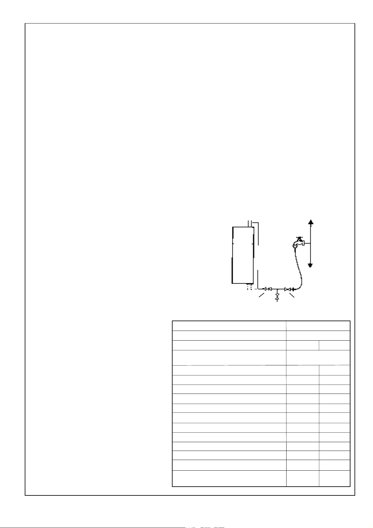
4. Filling
The system may be filled by one of the following methods:
a. Through a temporary hose connection from a draw-off tap
supplied from a service pipe under mains pressure. Where
the mains pressure is excessive a pressure reducing valve
must be used to facilitate filling.
i. Thoroughly flush out the whole system with cold
water.
ii. Fill and vent the system until the pressure gauge
registers 1.5 bar (21.5 psi) and examine for leaks.
iii. Check the operation of the safety valve by raising the
water pressure until the valve lifts. This should occur
within 0.3 bar (4.3psi) of the pre-set lift pressure.
iv. Release water from the system until the minimum
system design pressure is reached - 1.0bar (14.5 psi)
if the system is to be pre-pressurised.
CH RETURN
Double check valve
Boiler
CH FLOW
Hosepipe
(disconnect
after filling)
test cock
Hose
union bib
tap
Mains water
supply
stop valve
volume (litres)
25 1.6 1.8
50 3.1 3.7
75 4.7 5.5
100 6.3 7.4
125 7.8 9.2
150 9.4 11.0
175 10.9 12.9
190 11.9 14.0
200 12.5 14.7
250 15.6 18.4
300 18.8 22.1
Multiplying factors for
other system volumes 0.063 0.074
Classic Combi FF 280 - Installation
9
Page 10

GENERAL
5
SYSTEM REQUIREMENTS - CENTRAL HEATING - continued
The following fittings shall form a permanent part of the
system and shall be fitted in the order stated:
• A stop valve complying with the requirements of
BS. 1010:2 (the hose from the draw-off tap shall be
connected to this fitting).
• A test cock.
• A double check valve of an approved type.
Mains
water
supply
Non-return valve
Automatic
air vent
stop valve
Cistern
CH RETURN
CH
FLOW
Boiler
b. Through a cistern, used for no other purposes, via a ball
valve permanently connected directly to a service pipe
and/or a cold water distributing pipe.
The static head available from the cistern should be
adequate to provide the desired initial system design
pressure.
Note. The stop valve may remain open during normal
operation of the system if automatic water make-up is
required.
6. Thermostatic radiator valves
Caradon Ideal Ltd., support the recommendations made
by leading manufacturers of domestic heating controls that
heating systems utilising full thermostatic radiator valve
control of temperature in individual rooms should also be
fitted with a room thermostat controlling the temperature in
a space served by radiators not fitted with such a valve.
Such an arrangement will provide for a more efficient
control of the environment and will also avoid the
continuous running of the circulation pump during
programmed heating ON periods, saving electrical energy.
It is therefore strongly recommended that, when
thermostatic radiator valves are used, the space heating
temperature control over a living / dining area or a hallway
having a heating requirement of at least 10% of the boiler
output is achieved using a room thermostat, whilst other
rooms are individually controlled by thermostatic radiator
valves.
7. Open vented systems
The Classic Combi FF280 is designed for use with sealed
systems but can also be connected to open vented
systems if required.
Note. To comply with the relevant requirements of
BS.5449:1 and BS.6798 the positions of the cold feed and
vent must be as shown.
22mm open vent
450mm (min.)
450mm (min.) above
highest point in the
system
Water level
1500mm
(min.)
5. The maximum recommended system hydraulic losses are
given below:
System load kW 23.4 19.0 4.4
(Btu/h) (80 000) (65 000) (15 000)
Water flow rate l/min 22.5 24.8 5.7
(gal/h) (297) (327) (75)
Temperature °C 15 11 11
differential (°F) (27) (20) (20)
Pressure mbar 157 118 391
available for system (in. w.g.) (63) (47) (157)
Heating
load
150mm
(max.)
Inverted cold feed
connection - 15mm
Boiler
DOMESTIC HOT WATER REQUIREMENTS
The Classic Combi FF280 is suitable for connection to most
types of washing machine and dish washing appliances.
When connecting to suitable showers ensure that:
• The cold inlet to the boiler is fitted with an approved antivacuum or syphon non-return valve.
• Hot and cold water supplies to the shower are of equal
pressure.
IMPORTANT.
Provision must be made to accommodate the expansion of
DHW contained within the appliance if a non-return valve is
fitted to the DHW inlet. Refer to Frame 4.
10
Classic Combi FF 280 - Installation
Page 11

INSTALLATION
6
UNPACKING
The appliance is supplied as 2 separate modules (i.e. boiler module and Combi module) together with wall mounting plate
(Pack A1) in one Pack A.
Also supplied is a standard flue assembly for lengths up to 600mm (23 1/2"), rear or side flue outlet, in Pack B.
Optional extras, if ordered (Extension Duct Kit D, Vertex Flue Kit G, Roof Flue Kit H and 90° Flue Elbow Kit) are available in
separate boxes.
Unpack and check the contents.
Pack A Contents
z Combi module
z Boiler
z Pack A1
Pack A1 Contents
(contained within Pack A)
z Installation & Servicing Instructions
z User's Instructions
z Hardware Pack (listed below)
z Wall mounting template
z Wall mounting plate
z Stand-off brackets - 2 off
z Side outlet terminal mounting plate
INSTALLATION
Hardware Pack Contents
z No.14 x 50mm wood screws - 8 off
(for wall mounting plate)
z No.10 x 50mm wood screws - 8 off
(for side outlet plate and terminal
wall plate)
z Wall plugs - 16 off
z M6 nuts - 8 off
(for stand-off brackets)
z M6 screws - 8 off
(for stand-off brackets)
z M6 washers - 8 off
(for stand-off brackets)
Pack B Contents:
z Flue cutting support (cardboard) - 1 off
z Terminal wall plate - 1 off
z Sealing plate - 1 off
(for back panel)
z M8 x 12mm screw - 1 off
(for sealing plate)
z M8 washer - 1 off
(for sealing plate)
z 22mm compression elbow - 1 off
(for boiler / combi RETURN)
z 22mm brass elbow - 1 off
(for boiler / combi FLOW)
z Plastic elbow extractor - 1 off
z 7/8" sealing washers - 2 off
(for CH flow and return)
z 3/4" sealing washer - 1 off
z 1/2" sealing washers - 3 off
(for DHW inlet & outlet and
CH expansion vessel)
z 2 1/2" pozi-screw - 1 off
(for Combi module cover)
z Rubber gasket and screw - 1 off
(bypass valve)
z Terminal strip cover - 1 off
z M5 washer - 1 off
z M5 extended nut - 1 off
z Flue extension tube - 1 off
z M5 wing nut - 3 off
z IEC mains plug
z Boiler sealing plate
z Terminal grille assembly - 1 off
z Polyurethane foam seal 400 lg - 1 off
z No. 8 x 8 lg. Pozi pan screw hd. screws - 3 off
Classic Combi FF 280 - Installation
Flue terminal Terminal wall plate
11
Page 12
INSTALLATION
7
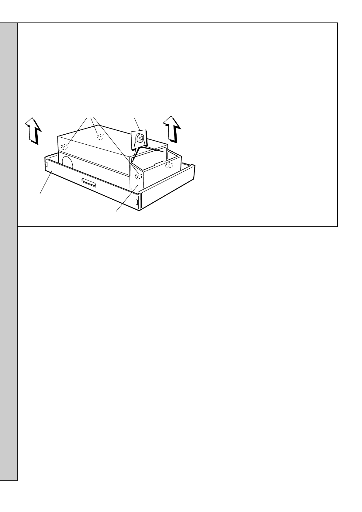
PACKAGING AND CASING REMOVAL
1. Unpack the boiler.
2. Remove the casing as follows and place to one side to
avoid damage:
a. Release controls pod fixing screws (a) 3 full turns only.
Remove the pod by pulling it forward to disengage from
the keyhole slots.
(b) Casing retaining
screws, 4 off
(a) Controls pod
fixing screws, 2 off
INSTALLATION
Packing base
Controls pod casing
b. Undo the 4 screws (b) retaining the
casing to the back panel.
c. Remove the casing in the direction of the
arrows.
3. Remove the boiler from its packaging base.
The boiler may now be stood upright on its
controls support protection frame to ease
handling and installation.
4. Unpack the flue assembly / extension flue
box(es).
12
Classic Combi FF 280 - Installation
Page 13
INSTALLATION REAR FLUE OUTLET ONLY
8
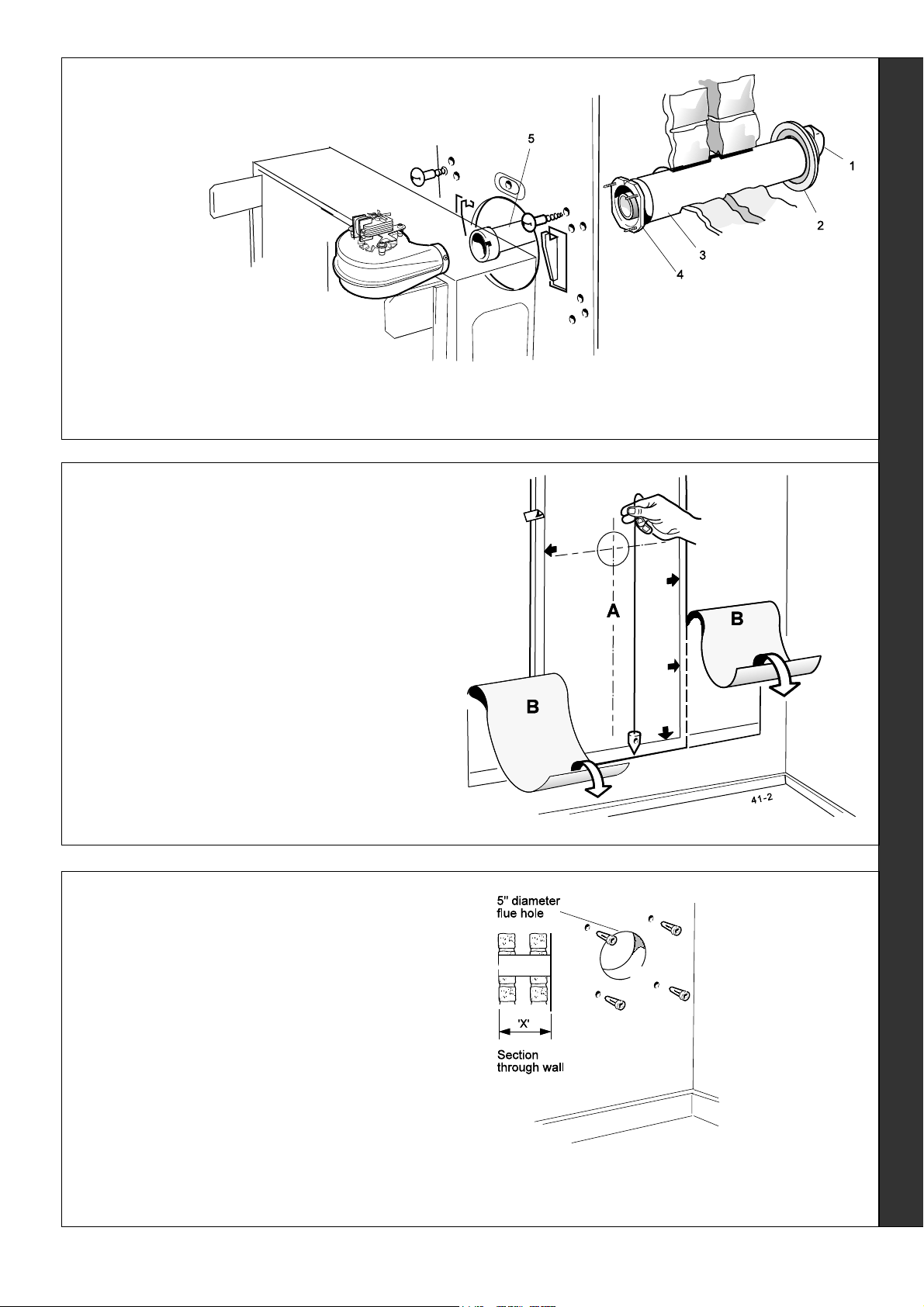
FLUE ASSEMBLY - Exploded View
1. An optional flue
duct extension
kit is required
for wall
thicknesses
greater than
600mm (23 1/2")
Refer to Frame
36.
LEGEND
1. Terminal.
2. Weather seal.
3. Flue assembly.
4. Boiler sealing plate.
5. Flue extension tube.
9
WALL MOUNTING TEMPLATE
Note. The template shows the positions for the fixing holes
and the flue hole centres for standard installation. Care
must be taken to ensure the correct holes are drilled.
1. Discard both sections B of the template.
2. Tape the template into the selected position.
3. Ensure squareness by hanging a plumb line as shown.
4. Mark onto the wall (if required) the following:
a. The 8 wall mounting plate screw positions and the
lower fixing screw positions.
b. The position of the flue duct.
Note. Mark the centre of the flue hole as well as the
circumference.
5. Remove the template from the wall.
10
PREPARING THE WALL
IMPORTANT.
Ensure that, during the cutting operation, masonry falling outside
of the building does not cause damage or personal injury.
1. Cut the flue hole preferably with a 125mm (5") core boring
tool, ensuring that the hole is square to the wall. If the hole
has been quite accurately cut with a drill, then making good
the wall faces is not essential as seals are provided at both
ends of the flue. However, both wall faces immediately around
the cut hole should be flat; make good if necessary. For less
accurate holes make good to approximately 125mm (5")
diameter at the 2 wall faces.
2. Drill 9 holes for the wall mounting plate with an 8mm (
masonry drill.
3. Insert the plastic plugs provided.
5/16")
Note. If the
terminal is to be
sited within 2540mm of a corner
or vertical pipe
(refer to Table 4)
then the hole
MUST be
accurately cut and
the rubber
weather seal
trimmed around
the groove
provided.
The terminal wall
plate need not be
fitted.
Note. Check all of the hole
positions BEFORE drilling
REAR FLUE OUTLET
Classic Combi FF 280 - Installation
13
Page 14

INSTALLATION
11
CUTTING THE FLUE - wall thicknesses of 114 to 600mm
Note.
If the stand-off brackets are used it is essential that 45mm
is added to the measured wall thickness when marking the
flue, to allow for the thickness of the brackets.
1. Measure and note the wall thickness X.
2. Mark the wall thickness onto the flue.
3. To ensure the tube is cut square, mark the flue all the
way round.
4. Cut to length X, using the cardboard ring for support.
5. Remove the cardboard ring and remove any burrs.
12
FITTING THE BOILER SEALING RING
TO THE FLUE
1. Fit the boiler sealing ring inside
the outer flue duct. Ensure the
boiler sealing ring is fully
engaged.
Ensure the notch aligns with
the groove on the outer flue
duct. This ensures correct
alignment of the flue terminal.
2. Drill 3 holes 3.2mm (1/8") dia. through the outer flue duct and
boiler sealing ring. Do NOT drill the inner flue duct.
3. Insert the self tapping screws,
provided, in order to fix the boiler
sealing ring in position.
4. Stick the self adhesive foam
strip, provided in the hardware
pack, onto the flue immediately
behind the boiler sealing ring.
13
Installations with bottom water connections
Secure the 2 stand-off
brackets to the wall
mounting plate, using the
eight M6 nuts, screws and
shakeproof washers
provided so that the plate is
located BEHIND the front
returns of the brackets, as
shown.
Note. If the clearances
above and below the boiler
are less than the length of
the pipes to be fitted behind
the wall mounting plate, then
refer to Frame 16.
IMPORTANT. To ensure
earth continuity, securing
screws MUST be fitted in the top holes (marked with the
symbol) with the shakeproof washers positioned under the screw
heads.
FITTING THE STAND-OFF BRACKETS
14
FITTING THE FLUE ASSEMBLY
1. Insert the flue extension tube into the flue assembly.
2. Insert the flue assembly through the hole far enough to
allow the rubber seal to unfold completely and form an
adequate seal on the outside wall.
3. Ensure the notch is at the top - this will aid the location of
the studs into the boiler back panel.
REAR FLUE OUTLET
14
15
WALL MOUNTING PLATE
1. Engage the plate
(or plate and
stand-off
brackets) on the
top fixing screws.
2. Locate six No.14
x 2" screws in the
lower fixing holes
and drive home
all screws.
3. Check with a
spirit level that
the plate is
vertical.
Classic Combi FF 280 - Installation
Page 15

16
PRE-PIPING
IMPORTANT.
For installations with bottom water connections only; the
following pipe runs must be made before the boiler is mounted
on the wall.
1. Make the connections to the fittings on top of the wall
mounting plate, as shown.
Note. For installations with a minimum top clearance of
100mm (4") the following fittings should be used.
• 22mm vented elbow (e.g. NIBCO)
• 22mm M & F elbow (e.g. ENDEX)
INSTALLATION
2. Extend the pipes down the wall, as shown, ensuring
that:
a. They terminate at least 50mm (2") below the bottom
of the wall mounting plate.
b. The CH flow and return pipes are vented to aid
filling.
Note. If the clearances above and below the boiler are less than the length of the pipes it will be necessary to position the pipe
runs behind the wall mounting plate BEFORE the plate is screwed to the wall.
FOR BOTH TOP AND BOTTOM WATER CONNECTIONS
If required, connection to the system pipework may now be made BEFORE the boiler is mounted on the wall.
PROCEED TO FRAME 42
17
PRE-WIRING
The mains supply and other external wiring may now be made, if required, BEFORE the boiler and Combi
modules are mounted on the wall - refer to Frames 46 to 49.
Classic Combi FF 280 - Installation
REAR & SIDE FLUE OUTLET
15
Page 16

INSTALLATION
18
MOUNTING THE BOILER
The boiler mounts onto
the wall plate hooks and
is retained by the central
M8 screw, plain washer
and large rectangular
plate.
Note. Have ready to hand the M8 screw,
plain washer and rectangular plate supplied
in the hardware pack.
1. Lift the boiler onto the wall mounting
plate hooks as shown.
DO NOT USE THE BURNER /
CONTROLS ASSEMBLY FOR LIFTING
IMPORTANT.
The boiler module MUST be positioned
CENTRALLY on the wall mounting plate.
Refer to the index mark on the back
panel.
2. Fit the M8 screw, washer and rectangular
plate to retain the boiler.
Note.
Before fully tightening the M8 screw, check
the boiler alignment using a spirit level, and
adjust as necessary with the jacking screw refer to Frame 3.
DO NOT USE THE BURNER / CONTROLS ASSEMBLY FOR LIFTING
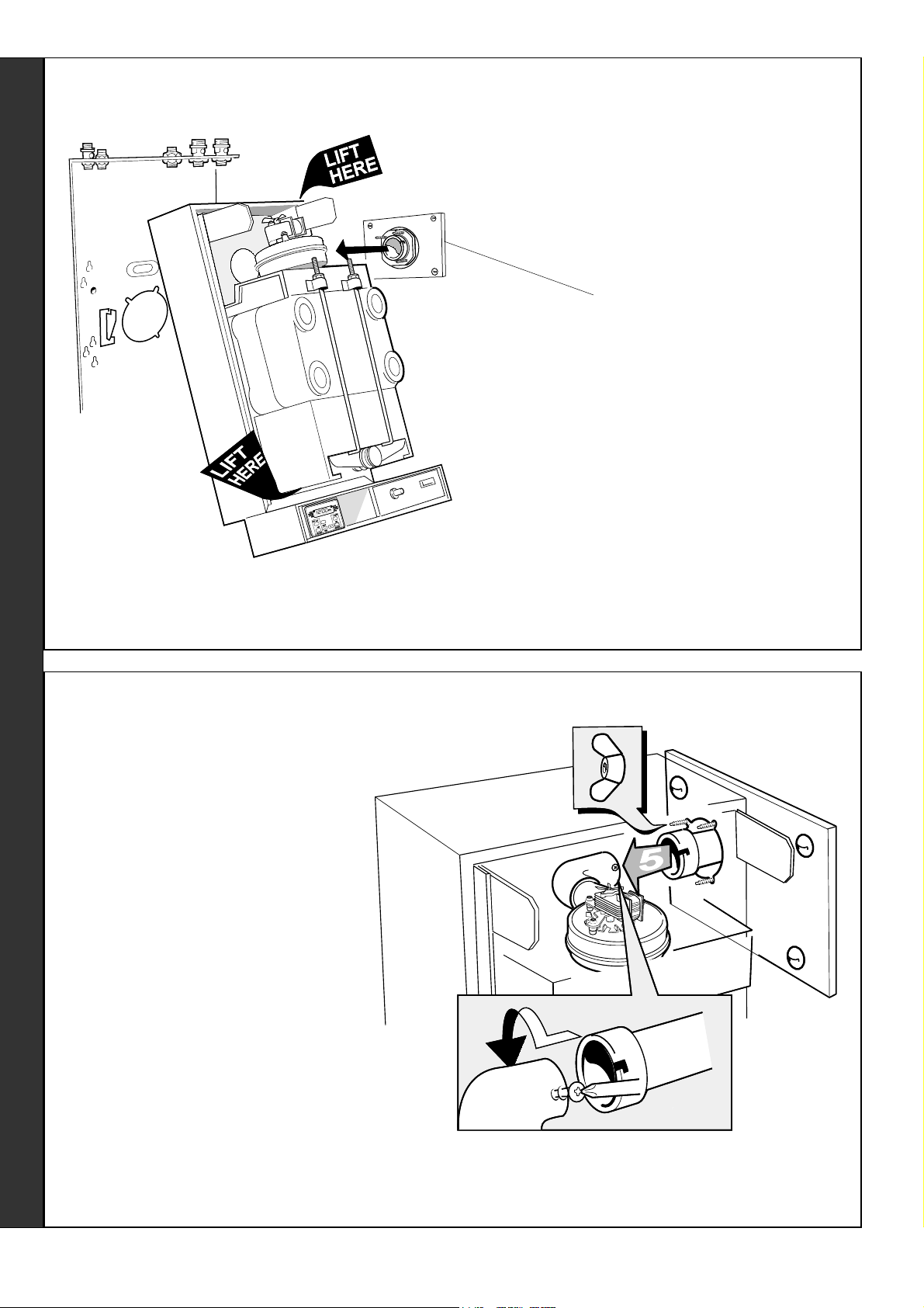
19
CONNECTING THE FLUE TO THE BOILER
1. Pull the flue through the wall mounting plate and locate
the 3 studs in the holes in the back panel.
2. Secure the flue to the boiler using the three M5 wing nuts
provided.
3. Pull the flue extension tube and engage onto the fan,
locate and secure with the M4 screw attached to the fan.
4. If a terminal wall plate is to be fitted proceed to Frame 34.
Note.
The sealing plate studs will locate in the back panel one way
only. This will ensure that the terminal grille is correctly
aligned.
APPLIANCES FITTED WITH A REAR OUTLET FLUE: PROCEED DIRECTLY TO FRAME 38
REAR FLUE OUTLET
16
Classic Combi FF 280 - Installation
Page 17

INSTALLATION
20
FLUE ASSEMBLY - Exploded View
For wall thickness 114mm to 600mm
1. An optional flue duct
extension kit is required for
lengths (distance from the
outside wall to the relevant
side of the boiler casing)
greater than 600mm (23 1/2")
Refer to Frame 3 .
21
WALL MOUNTING TEMPLATE
Note. The template shows the positions for the fixing holes and the flue hole centres
for standard installation.
SIDE FLUE OUTLET ONLY
LEGEND
1. Terminal
2. Weather seal
3. Flue assembly
4. Boiler sealing plate
5. Flue extension tube
Extended centre
line
Installations with top water connections only:
Tear off and discard the shaded portion of template B (refer to Frame 6)
Care MUST be taken to ensure the correct holes are drilled.
1. Separate the templates.
2. Tape both templates into the selected position, locating template B through an
extended centre line, as shown.
3. Ensure squareness by hanging a plumb line as shown.
4. Mark onto the wall the following:
a. The wall mounting plate screw positions (choose one from each group).
b. The 4 screw positions for the side outlet plate.
c. The position of the flue duct hole. (Ensure that the correct centre is marked,
depending upon whether the brackets are used or not)
Note. Mark the centre of the hole as well as the circumference.
d. The side of the casing nearest the flue outlet.
22
PREPARING THE WALL
5. Remove both templates from the wall.
IMPORTANT. Ensure that, during the cutting operation, masonry falling
outside of the building does not cause damage or personal injury.
1. Cut the flue hole preferably with a 125mm (5") core boring tool, ensuring
that the hole is square to the wall. If the hole has been accurately cut with
a drill then making good the wall faces is not essential as seals are
provided at both ends of the flue. However, both wall faces immediately
around the cut hole should be flat; make good if necessary. For less
accurate holes make good to approximately 125mm (5") diameter at the 2
wall faces.
2. Drill 8 holes with an 8mm (
provided, for the side mounting plate and the wall mounting plate.
3. Drill 4 holes with a 7mm (9/32") masonry drill and insert the plastic plugs
provided for the side mounting plate.
Note. If the terminal is to be sited within 25-40mm of a corner or vertical pipe (refer to
Table 4) then the hole MUST be accurately cut and the rubber weather seal trimmed
around the groove provided. The terminal wall plate need not be fitted.
5/16") masonry drill and insert the plastic plugs
Terminal
mounting
plate screw
and flue
duct hole
positions
SIDE FLUE OUTLET
Classic Combi FF 280 - Installation
17
Page 18

INSTALLATION
23
CUTTING THE FLUE
For flue lengths 114 to 600mm ONLY
24
FITTING THE FOAM SEAL
1. Measure the flue length required (i.e. the distance from
the side of the boiler to the outside face of the wall) refer to Frame 3.
2. Mark the flue length required on to the flue, measuring
from the groove near the terminal.
3. To ensure the tube is cut square, mark the flue all the
way round.
4. Insert the cardboard duct ring for support and cut to
length.
5. Remove cardboard duct ring and remove any burrs.
For flue lengths greater than 600mm, refer to
Frames 36 and 37- Flue extension ducts.
1. To determine the position for the foam seal, measure the
wall thickness and mark it onto the flue, measuring from
the groove near the terminal.
2. Wrap the self adhesive foam strip round the flue,
ensuring that the foam is on the terminal side of the line.
This seals the gap between the flue and the wall.
25
FITTING THE BOILER SEALING RING
TO THE FLUE
SIDE FLUE OUTLET
1. Fit the boiler sealing ring inside the outer flue duct.
Ensure the boiler sealing ring is fully engaged.
Ensure the notch aligns with the groove on the outer flue
duct. This ensures correct alignment of the flue terminal.
2. Drill 3 holes 3.2mm (
and boiler sealing ring.
duct.
3. Insert the self tapping screws, provided, in order to fix the
boiler sealing ring in position.
1/8") dia. through the outer flue duct
Do not drill the inner flue
26
FITTING THE FLUE ASSEMBLY
1. Insert the flue assembly through the hole far enough to
allow the rubber seal to unfold completely and form an
adequate seal on the outside wall. This will also ensure
the correct alignment of the flue terminal.
2. Ensure the notch is at the top. This will aid the location of
the studs into the boiler back panel.
18
Flue assembly
Classic Combi FF 280 - Installation
Page 19

27
FITTING THE STAND-OFF BRACKETS
Installations with bottom water connections only
Secure the 2 stand-off brackets to the wall mounting plate,
using the eight M6 nuts, screws and shakeproof washers
provided, so that the plate is located BEHIND the front returns
of the brackets, as shown.
Note.
If the clearances above and below the boiler are less than the
length of the pipes to be fitted behind the wall mounting plate
then refer to Frame 16.
IMPORTANT.
To ensure earth continuity, securing screws MUST be fitted in
the top holes (marked with the
washers positioned under the screw heads.
symbol) with the shakeproof
INSTALLATION
28
WALL MOUNTING PLATE
1. Locate two No.14 x
2" screws in the
wall mounting plate
top fixing holes and
screw home to
within 6mm (1/4")
of the wall surface.
2. Engage the plate
(or plate and standoff brackets) on the
screws.
3. Locate six No.14 x
2" screws in the
lower fixing holes
and drive home all
8 screws.
4. Check with a spirit
level that the plate
is vertical.
30
PRE-PIPING
IMPORTANT.
For installations with bottom water connections only
The pipe runs shown in Frame 16 must be made before the
boiler is mounted on the wall.
29
FITTING THE SIDE OUTLET PLATES
Note. If the boiler is fitted closer than 25mm to the side wall
the side outlet
plate must be
fitted now.
1. Split the side
outlet plate
into 2 down
the split line.
2. Fit the 2
halves of the
side outlet
plate to the
wall,
ensuring that
they are
behind the
boiler
sealing ring.
31
PRE-WIRING
The mains supply and other external wiring may now be
made, if required, before the boiler and Combi modules
are mounted on the wall.
Refer to Frames 46 to 49.
SIDE FLUE OUTLET
For installations with both top and bottom water connections
If required, connection to the system pipework may now be
made before the boiler is mounted on the wall - proceed to
'Water Connections', Frame 42.
Classic Combi FF 280 - Installation
19
Page 20
INSTALLATION
32
MOUNTING THE BOILER MODULE
Wall mounting plate
The boiler mounts
onto the wall plate
hooks and is
retained by the
central M8 screw,
plain washer and
large rectangular
plate.
Note. Have ready to hand the M8 screw, plain washer
and rectangular plate supplied in the hardware pack.
1. Lift the boiler onto the wall mounting plate hooks as
shown.
DO NOT USE THE BURNER / CONTROLS ASSEMBLY
FOR LIFTING
Terminal mounting plate
The air duct spigot engages
in the hole in the side panel.
IMPORTANT.
The boiler module MUST be positioned CENTRALLY on
the wall mounting plate. Refer to the index mark on the
back panel
2. Fit the M8 screw, plain washer and rectangular plate to
retain the boiler.
Note.
Before fully tightening the M8 screw, check the boiler
alignment using a spirit level, and adjust as necessary
with the jacking screw - refer to Frame 3.
DO NOT USE THE BURNER / CONTROLS ASSEMBLY FOR LIFTING
33
CONNECTING THE FLUE TO THE BOILER
SIDE FLUE OUTLET
1. Pull the flue through the side outlet plate and
locate the 3 studs in the hole in the side of
the boiler.
2. Secure the flue to the boiler using the three
M5 nuts, provided.
3. Insert the flue extension tube into the flue.
4. First remove the underside screw which is
not required then fit the 90
supplied with the boiler, onto the fan in the
direction required. Secure in position with the
screw.
5. Pull the flue extension tube and engage onto
the fan elbow and secure with the screw.
0
flue elbow,
Note.
The sealing plate studs will locate in the back
panel one way only. This will ensure that the
terminal grille is correctly aligned.
20
Classic Combi FF 280 - Installation
Page 21

34 TERMINAL WALL PLATE
This plate allows neat concealment and full compression of the
rubber seal. Its use is not essential if the flue hole and flue ducts
have been accurately cut and the outside wall face is flat.
1. Position the terminal wall plate over the terminal.
2. Drill 4 fixing holes with an 7mm (9/32") masonry drill.
3. Insert the 4 plastic plugs provided.
4. Secure the plate with 4 of the No.10 x 2" screws provided.
Note.
If the terminal is less than 2m (6' 6") above ground level, an
approved terminal guard should be fitted. Refer to the contents
list on Page 2.
35 FLUE EXTENSION DUCTS - For flue lengths greater than 600mm
INSTALLATION
PACK D Flue Extension Duct Kit contents
Flue connectors - 2 off
Extension duct
1.2m (42") long
36
FLUE EXTENSION DUCTS - continued
Support bracket
Use a maximum of two extension ducts only
General arrangement
Note. Side flue shown.
1. A maximum of 2 extension ducts (plus the standard flue
duct) may be used together.
2. Flue extensions of greater length than 1m (39") should be
supported with the bracket provided. If the stand-off
brackets have been used it is necessary, in order to keep
the flue aligned, to use the spacer bracket with the support
bracket.
Extension
tube
Boiler
Wall plug
No. 8 x 1/4" self
tapping screws - 14 off
No. 10 x 3" wood screw -1off
Flue length
Extension duct
Flue connector
Standard flue
SIDE FLUE OUTLET
Flue length Accessories Product No.
Up to 600 B Pack 1 off see Frame 3
600 to 1800 B Pack 1 off + D Pack, 1 off see Frame 3
1800 to 3000 B Pack 1 off + D Pack, 2 off see Frame 3
Classic Combi FF 280 - Installation
Terminal grille
21
Page 22

INSTALLATION
37
FITTING THE KIT
Note. Remove the cardboard duct ring from the end of the
standard flue duct (Pack B).
1. Remove the flue extension tube from the flue and place
safely to one side.
2. Fit the flue connector onto the standard flue duct.
3. Drill three 3.2mm (
the flue connector and the outer flue duct. Do NOT drill
the inner flue duct.
4. Insert the self tapping screws, provided, in order to fix the
connector in position.
5. Fit the inner flue duct into the connector.
6. Drill one 3.2mm (
inner flue duct, and secure in position with a self tapping
screw.
INSTALLATION
7. Fit the outer flue duct into the connector.
8. Drill three 3.2mm (1/8") dia equally spaced holes through
the flue connector and the outer flue duct. Do NOT drill
the inner flue.
9. Insert the self tapping screws, provided, in order to fix the
connector in position.
10. Repeat steps 5 - 9 if a second flue extension duct is
required.
11. Measure and mark the flue length required onto the flue,
measuring from the groove near the terminal.
12. To ensure the tube is cut square, mark the flue all the way
round.
13. Using the cardboard ring for support, cut to length.
14. Remove cardboard ring and remove any burrs.
15. For rear outlet flue: follow the procedure from Frame 8.
For side outlet flue: follow the procedure from Frame 20.
1/8") dia. equally spaced holes through
1/8") hole through the flue connector and
38
MOUNTING THE COMBI MODULE
1. Remove the Combi module from its box.
2. Lift off the Combi module cover, as shown.
View of Combi module with cover removed
Domestic
hot water
connections
Boiler
Safety valve drain pipe
Central
heating
connections
CH
expansion
vessel
3. Slacken the retaining screw, lift out the CH expansion
vessel and place safely to one side.
4. Remove the transit packing
5. Slacken the 2 retaining screws, lift out the CH expansion
vessel support bracket (complete with the pressure
gauge) and place safely to one side.
6. Fit the brass compression elbow (A), provided, on to the
boiler RETURN pipe and angle it approximately 60
shown in Frame 39 - do not tighten.
7. Push-fit the brass elbow (B), provided, on to the boiler
FLOW pipe, facing forwards, as shown. Apply soap
solution to ease fitting.
Note. Ensure
that the elbow is
pushed fully
home onto the
pipe.
8. Offer the Combi
module on top of
the boiler and
engage the
Combi module
RETURN pipe
within the brass
compression
elbow (A).
0
, as
22
Classic Combi FF 280 - Installation
Page 23

39
MOUNTING THE COMBI MODULE -
9. Swing the Combi module into
position, as shown, and snap the
Combi module FLOW pipe into
the brass elbow (B), ensuring
that it is pushed fully home to the
index mark on the Combi module
flow pipe.
Note. Should it be necessary to
realign the brass push-fit elbow
on the boiler flow pipe elbow, this
can be done using the plastic
extractor supplied in the
hardware pack.
DO NOT TIGHTEN THE BRASS
COMPRESSION ELBOW UNIONS
10. Connect the DHW inlet and
outlet pipes, safety valve drain
pipe and the CH flow and
return pipes to the bulkhead
fittings on top of the wall
mounting plate, using the 5
sealing washers provided.
Fully tighten. Refer to the view
opposite.
Notes.
a. Make the 2 outside connections first, i.e. DHW inlet and CH
flow. Tighten and draw the assembly up.
b. The automatic air vent may be removed, to gain better access
to the CH union connections.
11. Tighten the union nuts of the brass compression elbow (A).
continued
INSTALLATION
Automatic
air vent
INSTALLATION
CH
expansion
vessel
support
bracket
View of boiler module with CH expansion
vessel in the servicing position
12. Fit the CH expansion vessel support bracket.
13. Connect the pressure gauge capillary to the safety valve.
14. Hang the CH expansion vessel in the servicing position and
connect the flexible pipe, using the sealing washer provided.
Ensure that the pipe is positioned at 90
40
PRESSURE GAUGE HEIGHT ADJUSTMENT
It may be found necessary to adjust the position of the pressure
gauge in order for it to locate centrally in the aperture provided in the
module casing. This can be eased by checking the dimension from
the bottom of the pressure gauge bezel and the top of the boiler
casing, at the point when the expansion vessel is fitted.
Refer to diagram.
47 mm
0
to the vessel, as shown.
If adjustment is found to
be necessary undo the
2 locking nuts provided,
adjust the hexagon
headed screws until the
47mm dimension is
achieved and tighten
the locking nuts.
Hexagon
headed
screw and
locking
nut - 2 off
Classic Combi FF 280 - Installation
23
Page 24

INSTALLATION
41
GAS CONNECTION
Refer to 'Gas Supply' (page 5), for gas inlet service dimensions (Frame 2).
A minimum pressure of 20mbar MUST be available at the boiler inlet, with the boiler operating.
The main gas cock is on the left hand side of the gas control valve.
To facilitate connection the gas cock may be removed from the gas control valve.
42
WATER CONNECTIONS
CENTRAL HEATING
z When the CH load exceeds 20.5 kW (70 000 Btu/h) then
INSTALLATION
28mm (11/10") pipes should be used, both to and from
the boiler, as soon as is practicable after the initial 22mm
connection.
z For methods of filling refer to Frame 4.
1. Connect the CH flow and return
pipes to the boiler, as shown, or
to the pipework previously fitted
(Installations with bottom
connections only -refer to
Frame 16).
2. Ensure that the CH isolating
valves are open.
Compression
fitting
Isolating
valve
4. Ensure that the pump selector switch is set to No.3 and
that the pump is free to rotate.
a. Remove the vent plug.
b. Using a screwdriver, rotate the shaft several times.
c. Replace the vent plug.
Note. Some slight water leakage will occur.
Detail of pump
selector switch
Boiler
Vent plug
3. Fill and vent the system. Check for water soundness.
IMPORTANT. When filling:
a. Set the diverter valve manual lever to the OPEN
position.
Diverter valve
Note. The
manual
lever is
shown in
the
CLOSED
position
When filling is complete
return the lever to its
CLOSED position.
b. The cap on the automatic
air vent MUST be loose at
all times.
When filling there may be a
slight water leak from the
vent therefore electrical
connections should be
protected.
c. Vent the DHW calorifier
circuit via the manual air
vent on top of the calorifier.
Automatic air vent
DHW
calorifier vent
Pump
DOMESTIC HOT WATER SUPPLY
z The DHW supply pipe must be thoroughly flushed
BEFORE connecting to the boiler.
z The boiler incorporates a DHW filter therefore no
external device is necessary.
z It is recommended that a water softening device is fitted
on the cold water inlet supply, particularly in hard water
areas.
z Ensure that the mains supply pressure is sufficient to
provide the maximum delivery of domestic hot water
(approximately 0.9 bar, minimum). In areas where the
mains water pressure is known to be high (greater than
10 bar) it is recommended that a water governor is fitted
on the cold inlet supply to the boiler.
IMPORTANT. Devices incorporating non-return valves
MUST NOT be fitted to the DHW inlet, unless provision is
made to accommodate the expansion of the DHW
contained within the appliance. A suitable expansion
vessel of the 'Zilmet' or 'WMP' type should be fitted,
externally to the boiler, between the non-return valve and
the boiler.
1. Connect the hot and cold water
supply pipes to the boiler, as
shown, or to the pipework
previously fitted (Installations
with bottom connections
only - refer to Frame 16).
2. Open the domestic hot water
draw-off taps, clear air locks
and check for water
soundness.
Compression
fitting
Boiler
24
Classic Combi FF 280 - Installation
Page 25

43
WATER CONNECTIONS - continued
3. Domestic hot water flow rate setting:
a. Fully open all DHW taps in turn and ensure that water flows freely
from them.
b. Close all taps, except the furthest from the boiler, and check that the
boiler is firing at maximum rate.
c. Turn the DHW flow adjuster CLOCKWISE, to reduce the DHW flow
rate, until a rate of approximately 9.6 l/min (2.1gpm) is obtained at
the tap.
d. Turn off the DHW tap.
44
SAFETY VALVE OVERFLOW
Safety
valve
Route a 15mm pipe from
the safety valve overflow
connection, on top of the
wall mounting plate, to a
position outside of the
building so that any
discharge of water or
steam from the valve
cannot create a hazard
to the occupants or
damage to electrical
components and wiring.
overflow
connection
INSTALLATION
45
CH EXPANSION VESSEL LOCATION
Fit the CH expansion vessel in its working position and
secure with the retaining screw.
Working position
Hanging bracket
Retaining screw
Servicing position
INSTALLATION
46
ELECTRICAL CONNECTIONS
WARNING.
The appliance must be efficiently earthed.
A mains supply of 230 V ~ 50 Hz is required.
All external controls and wiring must be
suitable for mains voltage.
Wiring should be in 3-core PVC insulating
cable, not less than 0.75mm
BS. 6500 Table 16 and 70°C 'T' rating.
The supply connection must be made via a
double-pole switch, fused at 3 Amps, having a
3mm contact separation in both poles, serving
only the boiler and system controls.
Pictorial and schematic wiring diagrams are
shown in Frames 49 and 50.
2
(24 x 0.2mm) to
Note.
Ensure that the expansion vessel is orientated as shown,
to facilitate the fitting of the Combi module cover.
Note.
If the optional Programmer Kit is to be fitted,
refer to the instructions provided with the kit
and Frame 48 .
Classic Combi FF 280 - Installation
Flow wiring diagram
25
Page 26

INSTALLATION
47
WIRING THE BOILER
1. Plug the wall plate wiring harness lead
into the PCB (Board No.27) as shown.
INSTALLATION
4. Plug in the lead to the gas valve
2. Connect the earth lead from the wall plate wiring harness to the
earth post on the underside of the boiler control support.
3. Connect the lead from the wiring
harness to the flying lead
connection outside the control box.
PCB (Board No.27)
Connecting the mains supply
5. Wire the mains lead into the supply terminals marked L, N
and . Secure with the cable clamp.
6. Wire the control box cable into the terminal at the side of
the protection frame.
Notes.
a. The mains lead connection MUST be made in such a
way that, should the lead slip from the anchorage, the
current conductors become taut before the earthing
conductor.
b. The 'T' rating of the mains lead should be 70
c. Ensure that no basic insulation is accessible outside
of the terminal box and that the cable is secured into
the clamp on its supplementary insulation.
7. Fit the terminal strip cover under the control box and
secure it to the wall mounting plate with the extended nut
as shown.
0
C.
26
Classic Combi FF 280 - Installation
Page 27

48
EXTERNAL CONTROLS
External wiring must be in accordance with the current I.E.E.
(BS.7671) Wiring Regulations. Difficulty in wiring should not
arise, providing the following directions are observed. Refer to
the Pictorial and Schematic Wiring Diagrams (Frames 49 and
50).
a. Room thermostat
Remove the link between terminals RS1 and RS2. Wire in
the room thermostat. (Reference should be made to the
manufacturer's instructions).
INSTALLATION
1. CLOCK CONTROL OF HEATING ONLY
24 hr. DHW Preheat
b. Programmer
Remove the link between terminals CH and L1, and CL
and HW. Wire in the time switch according to Diagrams 1
and 2.
Note.
Wire the programmer and the room thermostat neutrals
into terminal CN
c. Frost protection
Central heating systems fitted wholly inside the house do
not normally require frost protection as the house acts as a
'storage heater' and can normally be left at least 24 hrs.
without frost damage.
However, if parts of the pipework run outside the house or
if the boiler will be left off for more than a day or so, then a
frost thermostat should be wired into the system.
This is usually done at the programmer, in which case the
programme selector switches are set to OFF - all other
controls MUST be left in the running position. The frost
thermostat should be sited in a cold place but where it can
sense heat from the system.
INSTALLATION
2. FULL CONTROL WITH PROGRAMMER & ROOM
THERMOSTAT
Timed DHW Preheat
Wiring should be as shown, with minimal disturbance to
other wiring of the programmer. Designation of the
terminals will vary but the programmer and thermostat
manufacturer's leaflets will give full details.
Diagram A shows a double pole frost thermostat, which
should suffice for all systems which do not use the OFF
terminals of the programmer.
Diagram B shows a 'changeover' frost thermostat, which
will cover most systems which do use CH OFF. If, however,
on such a system the HW pipework is in an isolated part of
the house, a second frost thermostat may be used to
protect it.
If in doubt, ask your installer for advice.
Note.
Secure any leads with the cable clamps provided.
Refit the terminal box cover.
Classic Combi FF 280 - Installation
27
Page 28
INSTALLATION
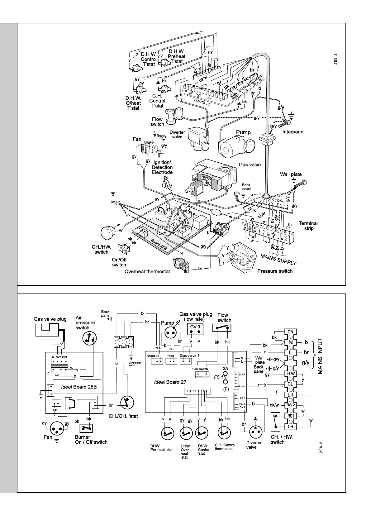
49
PICTORIAL WIRING DIAGRAM
LEGEND
b blue
bk black
INSTALLATION
br brown
r red
y yellow
w white
g/y green/yellow
bk/w black/white
v violet
gy grey
50
SCHEMATIC WIRING DIAGRAM
LEGEND
b blue
bk black
br brown
r red
y yellow
w white
g/y green/yellow
bk/w black/white
v violet
gy grey
28
Classic Combi FF 280 - Installation
Page 29
INSTALLATION
51
COMMISSIONING AND TESTING
(a) Electrical Installation
1. Checks to ensure electrical safety should be carried out by
a competent person.
2. ALWAYS carry out preliminary electrical system checks, i.e.
earth continuity, polarity, resistance to earth and short
circuit using a suitable test meter.
WARNING. Whilst effecting the required gas soundness test and purging air from the gas installation open all windows and
doors, extinguish naked lights and DO NOT SMOKE.
(b) Gas Installation
1. The whole of the gas installation, including the meter,
MUST be inspected and tested for soundness and purged
in accordance with the recommendations of BS. 6891.
2. Purging air from the gas installation may be expedited by
loosening the union on the gas service cock on the boiler
and purging until gas is detected.
3. Retighten the union and check for gas soundness.
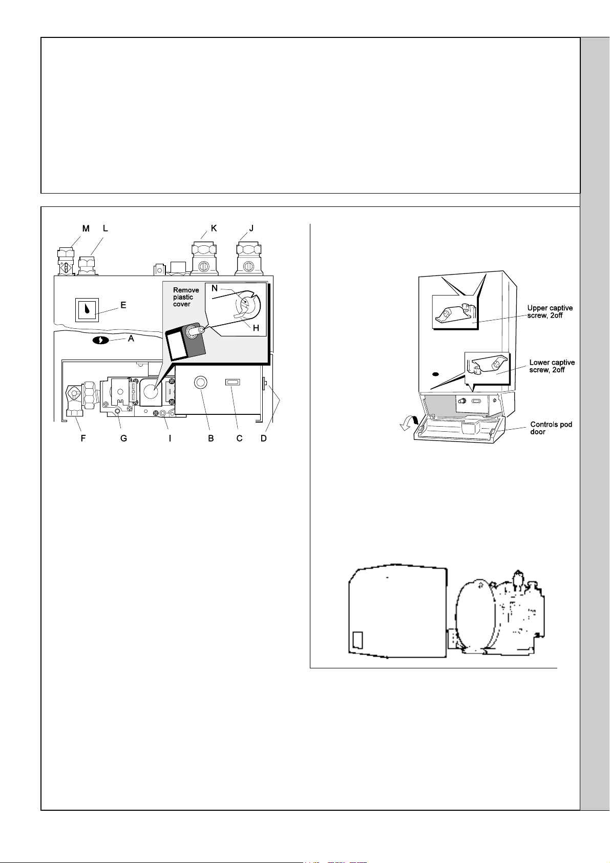
52
INITIAL LIGHTING
LEGEND
A Sightglass
B CH / HW switch
C Burner on/off switch
D Overheat thermostat reset button
E CH pressure gauge
F Gas service cock.
G Inlet pressure test point
H Main burner pressure
adjuster (outer)
I Burner pressure test point
J CH flow isolating valve
K CH return isolating valve
L DHW outlet
M DHW inlet isolating valve.
N Low rate adjusting
screw (inner)
1. Check that the electricity supply is OFF.
2. Check that all the drain cocks are closed and the central
heating isolating valves (J and K) and the domestic hot water
isolating valve (M) are OPEN. Check that the diverter valve
manual lever is in the CLOSED position. Refer to Frame 42.
3. Check that the gas service cock (F) is OPEN. Also check that
the CH switch (B) and burner on/off switch (C) are OFF.
4. Fit the boiler casing but do not fit the Combi module cover or
the controls casing pod.
FITTING THE BOILER CASING
Boiler module
z Lift the boiler casing up to the boiler assembly and secure with
4 captive screws.
z The casing must
seat correctly
and compress
the sealing strip
to make an
airtight joint.
Visually check
the side seals
but if side
clearances are
limited then
check that the
top and bottom
edges of the
casing are
correctly
located.
Controls casing pod
z Locate the pod on the 2 fixing screws. Push the pod forward to
engage in the keyhole slots and tighten the fixing screws.
Combi module cover
z Lift the cover up to the module and push forward to engage in
the keyhole slots. Secure with the 2
1/2" pozi screw provided.
INSTALLATION
WARNING.
Do NOT operate the boiler with the casing
removed as damage to the control box may result
5. Slacken the screw in the burner pressure test point (I) and
connect a gas pressure gauge via a flexible tube.
6. Switch the electricity supply ON and check that all external
controls are calling for heat: The pump will start.
TO LIGHT THE BOILER
7. Set the burner on/off switch to ON and the fan (and pump) will
start. After the fan has run for a few seconds the pilot solenoid
valve will open and the intermittent spark commence,
Classic Combi FF 280 - Installation
continuing until the pilot is established. The main burner will
then light at low rate, approximately 6.0mb (2.4 in.w.g.) burner
pressure. If this sequence does not occur refer to the Fault
Finding section.
8. Check that the pilot flame envelops the ignition / detection
electrode. If the pilot flame appears incorrect refer to 'Pilot
Burner Replacement' in the Servicing section.
9. Test for gas soundness around ALL boiler gas components,
using leak detection fluid. Particularly check gas valve flanges.
10. Set the burner on/off switch to OFF.
29
Page 30

INSTALLATION
53
INITIAL LIGHTING - continued
CENTRAL HEATING
1. Set the CH/HW switch (B) to CH & HW, and the burner on/
off switch (C) to ON. Check that:
a. The pump is running.
b. The diverter valve energises - no resistance should be
felt when the manual lever is moved by hand.
c. The fan starts and the main burner cross-lights
smoothly at maximum rate.
Note. The burner may fire initially at low rate but should
increase to maximum rate after 1-2 minutes.
2. Operate the boiler for 10 minutes to stabilise the burner
temperature.
3. The boiler CH control operates at a burner pressure of
16.0mb (6.4 in.w.g.). Should it be necessary to adjust the
INSTALLATION
burner pressure remove the plastic cover (refer to Frame
52) then turn the outer adjusting screw (H) in either
direction until the correct pressure is achieved.
Note. Burner setting pressures and boiler performance details
are given in Tables 2 & 3 and on the data plate, located on the
control support frame.
54
GENERAL CHECKS
DOMESTIC HOT WATER MODE
1. Set the CH/HW switch (B) to HW ONLY and the burner on/off
switch (C) to ON. The pump should start circulating water
through the DHW calorifier and the burner should fire at
minimum rate for about 3 minutes, preheating the DHW
calorifier.
a. If no DHW is drawn off the boiler will fire periodically for a
short time to maintain the calorifier temperature.
b. The DHW preheat operates 24 hours a day unless a
programmer is fitted, when it can be timed.
2. Fully open a DHW tap. Check that the pump starts and the main
burner fires at maximum rate. Check that DHW is delivered.
3. Reduce the DHW draw-off rate to the minimum required to
keep the boiler firing and check that the burner pressure
reduces to low rate in response to DHW temperature rise.
4. Close the DHW tap and check that the main burner
extinguishes and the pump stops.
CENTRAL HEATING AND DOMESTIC HOT WATER MODE
1. Set the CH/HW switch (B) to CH & HW. Check that the main
burner fires at the maximum rate.
2. Fully open a DHW tap and check that the hot water is delivered.
3. Close the DHW tap and turn off the CH/HW switch (B). Check
that the main burner extinguishes and the pump stops.
4. Check the correct operation of the programmer, if fitted, and all
other system controls. Operate each control separately and
check that the main burner responds.
5. Remove the pressure gauge and tube. Tighten the sealing
screw in the pressure test point, ensuring that a gas-tight seal
is made.
WATER CIRCULATING SYSTEM
1. With the system COLD, check that the initial pressure is
correct to the system design requirements. For prepressurised systems this should be 1.0 bar (14.5 psi).
2. Set the RED fill pressure indicator on the pressure gauge (E)
to the initial system pressure. Refer to Frame 4 'Filling'.
DOMESTIC HOT WATER
1. With the burner firing as above, fully open a DHW tap and
set the CH/HW switch (B) to HW ONLY. Check that:
a. The pump continues to run.
b. The diverter valve de-energises.
c. The burner continues to fire at maximum rate.
2. Reduce the DHW draw-off rate to the minimum required to
keep the boiler firing. The DHW control operates at a
burner pressure of 6.0mb (2.4 in.w.g.). Should it be
necessary to adjust the burner pressure turn the inner
adjusting screw (N) in either direction until the desired
burner pressure is achieved. Refer to Frame 52.
Note. Recheck the maximum burner pressure (CH) after
setting the minimum burner pressure (HW) and adjust as
necessary.
3. Turn off the DHW tap and set the burner on/off switch to
OFF.
3. With the system still hot, examine all water connections for
soundness. The system pressure will increase with
temperature rise but should not exceed 2.5 bar (36.6 psi).
4. With the system still hot, turn off the gas, water and electricity
supplies to the boiler and drain down, in order to complete the
flushing process.
5. Refill and vent the system, as described in 'Guide to System
Requirements', clear all air locks and again check for water
soundness.
6. Reset the system initial pressure to the design requirement.
7. Balance the system.
FINALLY
1. Fit the Combi module cover. Refer to Frame 52.
2. Refit the controls casing pod and tighten the 2 front fixing
screws.
3. Set the controls to the user's requirements and close the pod
door.
•
The design water output temperatures are as
follows:
Central Htg 820C maximum
0
Domestic 70
Hot Water 35
C approx at 3.5 l/min (nominal) draw-off
0
C temperature rise at 9.6 l/min draw-off
• If a programmer is fitted refer to the programmer
instructions.
4. Check that the casing is seated correctly and is compressing
the sealing strip all around the casing.
IMPORTANT.
It is absolutely essential to ensure, in practice, that products
of combustion discharging from the terminal cannot re-enter
the building, or any other adjacent building, through
ventilators, windows, doors, other sources of natural air
infiltration or forced ventilation/air conditioning.
If this should occur the appliance must be TURNED OFF
IMMEDIATELY and the local gas supplier called to
investigate.
WARNING. Do not operate the boiler with the casing removed.
30
Classic Combi FF 280 - Installation
Page 31

55
HANDING OVER
After completing the installation and commissioning of
the system the installer should hand over to the
householder by the following actions:
INSTALLATION
1. Hand the User's Instructions to the Householder and
explain his or her responsibilities under the Gas Safety
(Installation and Use) Regulations 1994.
2. Draw attention to the Lighting Instruction label affixed to the
controls pod door.
3. Explain and demonstrate the lighting and shutting down
procedures.
4. The operation of the boiler and the use and adjustment of
ALL system controls should be fully explained to the
Householder, to ensure the greatest possible fuel economy
consistent with household requirements of both heating
and hot water consumption.
Advise the User of the precautions necessary to prevent
damage to the system and to the building, in the event of
the system remaining inoperative during frosty conditions.
5. Explain the function and the use of the boiler heating and
domestic hot water controls.
6. Explain the function of the boiler overheat thermostat and
emphasise that if cutout occurs, the boiler should be
turned off and a CORGI registered installer consulted.
7. Explain and demonstrate the function of time and
temperature controls, radiator valves etc., for the
economic use of the system.
8. If any Programmer Kit is fitted, then draw attention to
the Programmer Kit User's Instructions and hand them
to the Householder.
9. Loss of system water pressure
Explain that the dial on the Combi module indicates the
central heating system pressure and that if the normal
COLD pressure of the system (indicated by the red
arrow in the dial) is seen to decrease over a period of
time then a water leak is indicated. In this event a
CORGI registered installer should be consulted.
DO NOT FIRE THE BOILER IF THE PRESSURE HAS
REDUCED TO ZERO FROM THE ORIGINAL
SETTING
10. Stress the importance of regular servicing by a CORGI
registered installer and that a comprehensive service
should be carried out AT LEAST ONCE A YEAR.
INSTALLATION
Classic Combi FF 280 - Installation
31
Page 32

SERVICING
56
SCHEDULE
57
BOILER CASING REMOVAL
To ensure the continued safe and efficient operation of the
appliance it is recommended that it is checked at regular
intervals and serviced as necessary. The frequency of
servicing will depend upon the installation condition and
usage, but should be carried out at least annually. It is the
law that any service work must be carried out by a CORGI
registered installer.
a. Light the boiler and, using the flue sampling point
(provided on the top RH side of the back panel), carry
out a pre-service check, noting any operational faults.
b. Clean the main burner.
c. Clean the heat exchanger.
d. Clean the main and pilot injectors.
e. Remove any debris from inside the base of the casing.
f. Check that the flue terminal is unobstructed and that
the flue system, including the inner cover, is sealed
correctly.
g. If the appliance has been installed in a compartment,
check that the ventilation areas are clear.
The servicing procedures are covered more fully in
Frames 57 to 63 and must be carried out in sequence.
WARNING. Disconnect the electrical supply and turn off the
gas supply.
IMPORTANT. After completing the servicing or exchange
of components always test for gas soundness and carry
out functional checks as appropriate.
When work is complete the casing MUST be correctly
refitted, ensuring that a good seal is made.
SERVICING
T
he boiler must NOT be operated if the casing is not
fitted.
Note. In order to carry out either servicing or replacement
of components, the boiler casing must be removed
(Frame 57).
Combi Module Cover
Release the securing screw and withdraw the cover.
Boiler Casing
1. Open the controls pod door.
2. Release the 4 captive screws at the top and bottom of the
casing. Lift the casing off the boiler and retain in a safe
place .
3. Isolate the gas supply at the service cock fitted to the
boiler. Refer to Frame 64.
58
BURNER AND AIR BOX REMOVAL
1. Remove the screw retaining the front burner support bracket
to the combustion chamber. Remove the M5 pozi-screw
situated at the LH bottom rear of the burner and pull the
burner downward to disengage the retention tab. Remove
burner to a safe place for inspection and cleaning.
2. Remove the control box fixing screw. Pull the box forward
and downward to disengage.
32
3. Pull the HT lead connection off the printed circuit board and
pull the lead upwards through the bottom panel grommet.
4. Remove the 4 screws retaining the air box /pilot assembly
to the vertical manifold and carefully remove the assembly.
Classic Combi FF 280 - Installation
Page 33
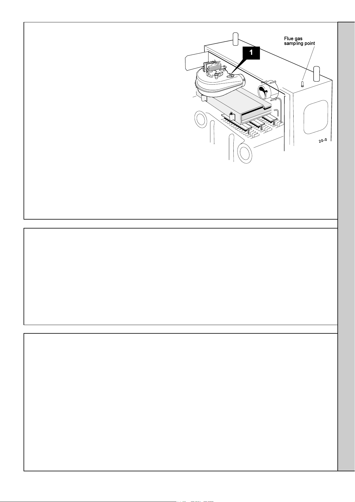
59
CLEANING THE FAN ASSEMBLY / THE FLUEWAYS
1. Remove the 2 silicon rubber tubes from the fan sensing
points.
2. Disconnect the fan leads and the fan earth connection.
3a. Rear flue
Slacken the M4 screw securing the flue connector to the
fan. Disconnect the connector from the fan and slide into
the flue.
3b. Side flue
Slacken off two M4 screws securing the flue elbow and
flue connector. Disconnect the flue connector from the
elbow and slide into the flue. Remove the flue elbow.
4. Disconnect the silicon rubber tube from the rear of the
collector hood.
5. Slacken the two M5 nuts on the front tie rods, releasing
the tie rods from the combustion chamber.
6. Remove the M5 central fixing screw at the rear of the
collector hood and remove collector hood/fan assembly.
7. Check that the fan impeller runs freely. Remove any
debris from the impeller with a soft brush.
8. Remove the flue baffle clips and remove the flue baffles.
SERVICING
9. Remove all loose deposits from the heat exchanger,
particularly between the fins, using a suitable brush.
10. Reassemble in reverse order, ensuring that the fan leads,
fan earth connection and 3 sensing tubes are reconnected.
60
CLEANING THE BURNER AND PILOT ASSEMBLY
1. Brush off any deposits that may have fallen on to the
burner head, ensuring the flame ports are unobstructed,
and remove any debris that may have collected.
Note. Brushes with metallic bristles must not be used.
2. Remove the main burner injector and ensure there is no
blockage or damage. Clean or renew as necessary.
3. Refit the injector, using an approved jointing compound
sparingly.
4. Inspect the pilot burner and ignition / detection electrode.
Ensure that they are clean and in good condition. Check
that:
61
RE-ASSEMBLY
Reassemble the boiler in the following order:
1. Refit the flue baffles.
2. Inspect the collector hood rope gasket and replace, if
necessary, ensuring that the self adhesive rope is fitted
centrally onto the lip of the collector hood /fan assembly.
The boiler efficiency will be adversely affected if incorrectly
fitted.
Refit the collector hood and retain with the 2 front tie rods
and the rear central fixing screws. Tighten the nuts and
screw. Ensure that the sealing gasket is compressed.
3. Refit the 3 sensing tubes and reconnect the electrical
leads.
4. Refit the air box assembly and burner. Ensure that the
burner front fixing is refitted.
a. The pilot burner injector is not blocked or damaged.
Refer to Frame 68 for removal details.
b. The pilot burner is clean and unobstructed.
c. The ignition / detection electrode is clean and
undamaged.
e. The ignition / detection lead is in good condition.
f. The spark gap is correct (Frame 68). Clean or renew as
necessary.
Note. The pilot shield is located around the pilot assembly
bracket and is located by the electrode retaining nut.
5. Refit the control box.
6. Reconnect the gas supply and the electrical wiring. Refer to
Frames 41 and 46.
7. Check the sightglass in the boiler casing. Clean or renew
as necessary. Refer to Frame 65.
8. Check for gas soundness. Check the gas service cock and
pressure test point.
9. Refit the boiler casing and tighten the 4 captive screws.
IMPORTANT.
When work is complete the casing must be correctly
refitted. Ensure that a good seal is made.
10. Close the controls pod door.
SERVICING
Classic Combi FF 280 - Installation
33
Page 34
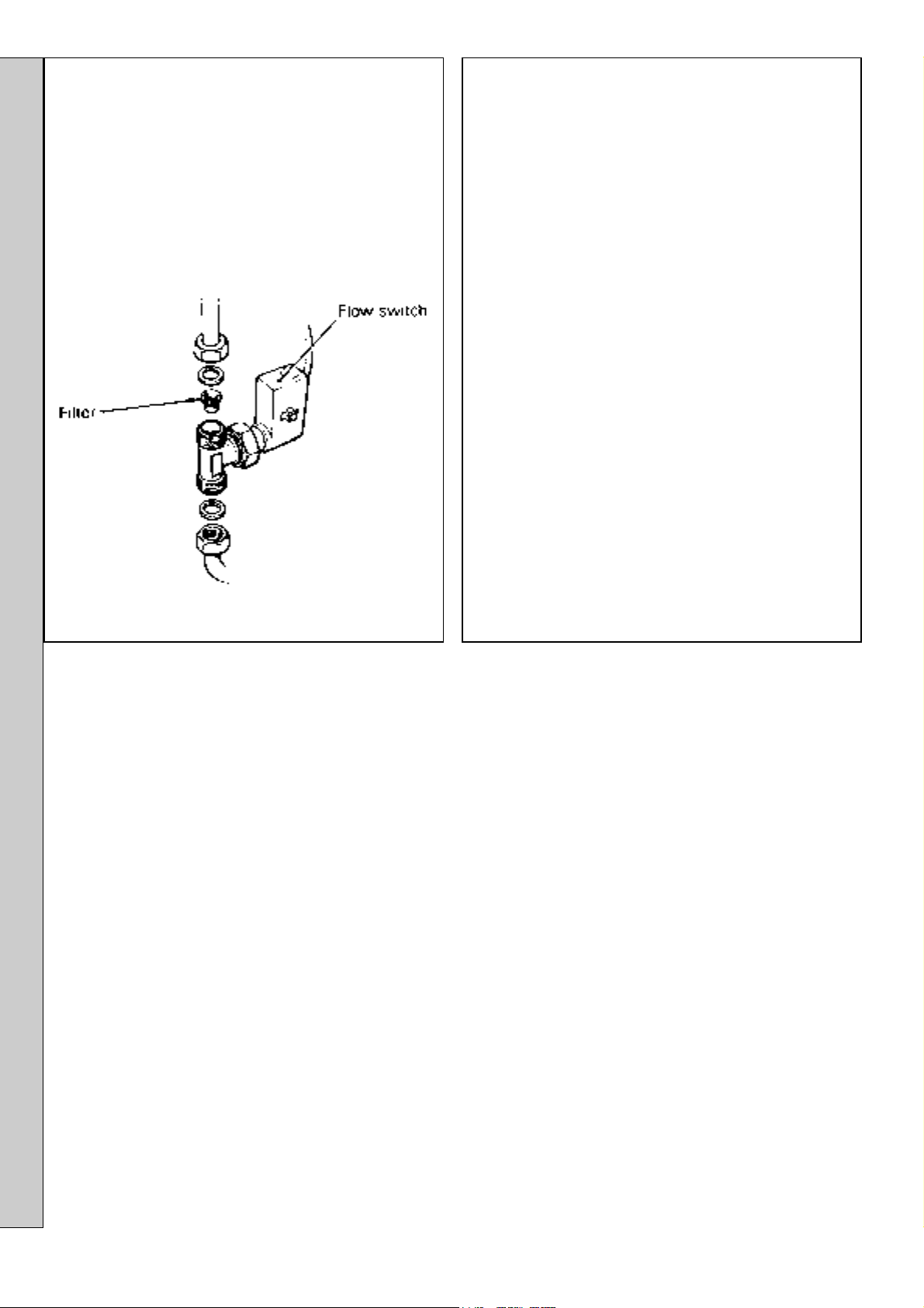
SERVICING
62
CLEANING THE DOMESTIC HOT
WATER (DHW) FILTER
63
GAS PRESSURE ADJUSTMENT
1. Remove the DHW flow switch. Refer to Frame 79.
2. Prise the filter from the housing in the flow switch inlet
and clean or renew as necessary.
PILOT
Light the boiler and check that the pilot flame envelops the
ignition / detection electrode.
The pilot is factory set to maximum and no further
adjustment is possible. If, however, the pilot flame length is
incorrect then remove and inspect the pilot injector. Refer to
Frame 68.
Relight in accordance with 'Initial lighting', Frames 52 and
53.
MAIN BURNER
After any servicing, reference should be made to Table 2,
which quotes details of the rated output with the related
burner setting pressure and the heat input.
Any required adjustments should be made by using the
pressure adjustment screw.
Refer to 'Initial Lighting', Frame 52.
SERVICING
34
Classic Combi FF 280 - Installation
Page 35
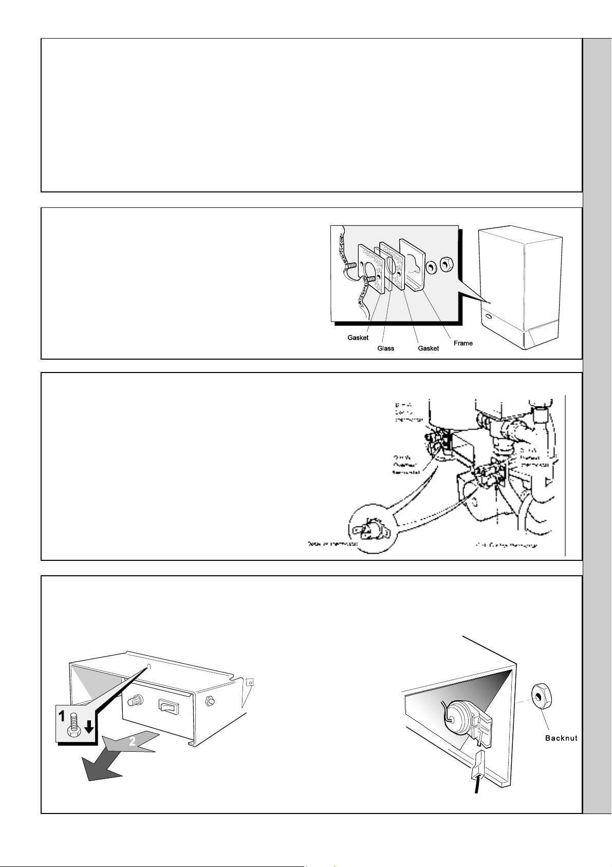
REPLACEMENT OF PARTS
SERVICING
64
GENERAL
When replacing any component:
1. Isolate the electricity supply.
2. Turn OFF the gas supply.
3. Remove the boiler casings. Refer to Frame 57.
IMPORTANT. When work is complete the casing must be
correctly refitted, ensuring that a good seal is made.
THE BOILER MUST NOT BE OPERATED IF THE CASING IS NOT FITTED
65
SIGHTGLASS REPLACEMENT
1. Refer to Frame 64.
2. Unfasten the 2 nuts and washers holding the sightglass
assembly to the casing front panel.
3. When fixing the new assembly ensure that the parts are in
the correct order. The frame must have the return edge at
the bottom.
4. Retighten the 2 nuts to ensure an airtight seal. DO NOT
OVERTIGHTEN.
5. Replace the boiler casing. Refer to Frame 52.
Note. In order to assist fault finding, the control box printed circuit
board is fitted with 4 indicator lights which represent the following
boiler conditions:
Neon I
Neon I
Neon I
Neon SGI Flashes to indicate spark operation
Air pressure switch made.
1
Fan voltage indication
2
Main supply to PCB 25B.
3
(stops after detection).
66
DHW PREHEAT, CONTROL, OVERHEAT AND CH CONTROL THERMOSTAT
REPLACEMENT
1. Refer to Frame 64.
2. Release the retaining screw and hang the CH expansion
vessel in the servicing position. Refer to Frame 45.
3. Remove the 2 securing screws and withdraw the faulty
thermostat.
4. Pull off the 2 electrical leads from the thermostat.
5. Fit the new thermostat and re-assemble in reverse order
(polarity is immaterial).
67
CH OVERHEAT THERMOSTAT REPLACEMENT
Refer also to Frame 64
1. Remove the control box fixing screw.
2. Pull the box forward and downward to disengage.
3. To remove the overheat
thermostat pull off the
electrical connections at
the thermostat. Remove
the backnut retaining the
thermostat to the bracket.
Remove the thermostat
from the heat exchanger
pocket.
SERVICING
Classic Combi FF 280 - Installation
4. Reassemble in reverse
order.
35
Page 36

SERVICING
68
PILOT BURNER REPLACEMENT
1. Refer to Frame 64.
2. Remove the burner and air box assembly.
Refer to Frame 58.
3. Remove the electrode retaining nut and remove the pilot
shield and electrode.
4. Unscrew the central pilot fixing screw and lift the pilot clear
of the pilot injector. The pilot injector may now be
unscrewed if required.
5. Replace the pilot burner and retain with the M4 screw
previously removed. Ensure that the copper sealing washer
is replaced when refitting the pilot injector.
69
SPARK ELECTRODE AND LEAD REPLACEMENT
1. Refer to Frame 64.
2. Remove the burner and air box assembly. Refer to Frame 58.
3. Remove the electrode retaining nut.
4. Remove the pilot shield.
5. Remove the spark electrode and integral lead.
6. Fit the new electrode and lead in reverse order.
SERVICING
Ensure that the pilot shield is replaced.
7. Check the spark gap. Refer to Frame 68.
8. Replace the boiler casing.
9. Check the pilot ignition.
6. Replace the electrode and pilot shield, retaining both with
the electrode nut. Check the spark gap.
7. Replace the box assembly.
8. Replace the burner.
9. Replace the boiler casing.
10. The pilot is factory set to maximum and no further
adjustment is possible. Ensure that there is an inlet
pressure of 20 mbar available. Also check burner ignition
and cross-lighting.
70
MAIN BURNER & MAIN BURNER INJECTOR REPLACEMENT
1. Refer to Frame 64
2. Remove the screw retaining the front burner support bracket
to the combustion chamber.
3. Remove the M5 pozi screw and washer, situated at the left
hand bottom rear of the burner. Pull the burner downward to
disengage the retention tab and remove the burner.
4. At this stage the main burner injector can be removed,
checked, cleaned or replaced as required. Ensure that an
approved jointing compound is used sparingly.
5. Fit the new burner, ensuring that the retention tab is correctly
located in the air box slot.
6. Refit the M5 retaining screw and washer.
7. Refit the boiler casing.
8. Check the burner for cross-lighting and flame stability.
36
Classic Combi FF 280 - Installation
Page 37

COMBUSTION CHAMBER INSULATION REPLACEMENT
71
1. Refer to Frame 64
2. Remove the burner and air box assembly. Refer to Frame 58.
3. Remove the tie rods and combustion chamber.
4. Remove the 2 side panel retaining brackets.
5. Remove the side insulation panels.
6. Remove the front and rear insulation panels.
7. Fit the new front and rear insulation panels.
8. Fit the new side panels and retain with the brackets and
screws previously removed.
9. Refit the combustion chamber and tie rods.
10. Re-assemble the rest of the appliance in reverse order.
72
GAS CONTROL VALVE REPLACEMENT
SERVICING
Note. Also refer to Frames 93 & 94, 'Exploded Views' , for illustration of the procedure detailed below.
1. Refer to Frame 64.
2. Remove the burner support bracket, burner and air box
assembly. Refer to Frame 58.
3. Remove the control box fixing screw. Pull the box
forward and downward to disengage.
4. Remove the gas control valve electrical connections.
5. Disconnect and remove the gas union from the gas
control valve.
6. Whilst supporting the gas control valve, remove the 2
screws retaining the manifold to the back panel.
73
FAN REPLACEMENT
1. Remove the 2 silicon rubber tubes from the fan sensing points.
2. Disconnect the fan leads and the fan earth connection.
3a. Rear flue: Slacken the M4 screw securing the flue connector to the fan.
Disconnect the connector from the fan and slide into the flue.
7. Remove the gas control / manifold assembly.
8. Remove the 4 screws retaining the manifold to the gas
control valve and fit the manifold to the new gas control
valve. Ensure that the new control is fitted the correct way
round (an arrow engraved on the back indicates the
direction of flow).
Note. Remove the gas cock stub and refit into the new
gas control valve. Use an approved jointing compound on
the pipe stub.
9. Reassemble in reverse order.
10. Replace the boiler casing.
11. Check the gas valve operation / gas soundness.
SERVICING
3b. Side flue: Slacken off two M4 screws securing the flue elbow and flue
connector. Disconnect the flue connector from the elbow and slide into
the flue. Remove the flue elbow.
4. Disconnect the silicon rubber tube from the rear of the collector hood.
5. Slacken the two M5 nuts on the front tie rods, releasing the tie rods from
the combustion chamber.
6. Remove the M5 central fixing screw at the rear of the collector hood and
remove collector hood/fan assembly.
7. Remove the three M4 screws retaining the fan to the collector hood.
8. Reassemble in reverse order, ensuring the fan leads, fan earth
connection and 3 sensing tubes are reconnected.
Classic Combi FF 280 - Installation
9. Refit the boiler casing.
10. Check the boiler operation.
37
Page 38

SERVICING
74
AIR PRESSURE SWITCH (APS) REPLACEMENT
1. Refer to Frame 64.
2. Remove the control box fixing screw. Pull the box forward
and downward to disengage.
3. Pull off both sensing tubes from the APS and remove the
cover.
4. Remove the 3 electrical connections from the APS.
5. Remove the switch from the controls box.
6. Connect the new switch in reverse order.
7. Refit the control box.
8. Refit the boiler casing.
9. Check the boiler operation.
75
BURNER ON/OFF AND CH/HW SWITCH REPLACEMENT
1. Refer to Frame 64.
2. Remove the control box fixing screw, pull the box forward
and downward to disengage.
3. Disconnect the 2 electrical leads from the switch.
4. BURNER ON/OFF SWITCH ONLY
Compress the retaining clips and prise the defective switch
out of the front panel.
CH / HW SWITCH ONLY
a. Pull off the knob.
b. Remove the backnut and withdraw the switch.
5. Connect the new switch in reverse order. Ensure that the
switch is the correct way round, i.e. with the terminals
SERVICING
towards the right, as shown (burner on/off switch) or that
the switch is correctly orientated (CH/HW switch). Polarity
is immaterial
6. Refit the boiler casing.
7. Check the switch operation.
76
PRINTED CIRCUIT BOARD (PCB) REPLACEMENT
Note. Refer to Frames 93 and 94, 'Exploded Views' for illustration of the procedure detailed below.
1. Refer to Frame 64.
2. Remove the control box fixing screw. Pull the box forward
and downward to disengage.
3. Remove the HT lead from the PCB
4. Remove the 4 push-in electrical connectors from the PCB.
5. Remove the neutral wire on the PCB from its connection to
the back of the socket inside the control box.
6. Remove the earth wire on the PCB from its connection to
the earth stud inside the control box.
7. Remove the 2 connections from the on/off switch and
remove the switch.
8. Compress the barbs on the PCB stand-offs to release the
PCB from the box.
9. Fit the new PCB and reassemble in reverse order.
10. Refit the boiler jacket.
11. Check the operation of the boiler.
12. Check the ignition operation.
38
Classic Combi FF 280 - Installation
Page 39

77
LOGIC PCB 27 REPLACEMENT
1. Refer to Frame 64 (The Combi module cover only need be removed.)
2. Release the retaining screw and hang the CH expansion vessel in the servicing
position. Refer to Frame 45.
3. Withdraw the PCB and unplug the 8 electrical leads
(A to H).
4. Fit the new PCB 27 and re-assemble in reverse order.
Logic PCB 27
SERVICING
78
DIVERTER VALVE ACTUATOR REPLACEMENT
1. Refer to Frame 64 (The Combi module cover only need be
removed.)
2. Release the retaining screw and hang the CH expansion
vessel in the servicing position. Refer to Frame 45.
3. Disconnect the diverter valve at the inline
connector.
4. Release the captive screw (A)
and lift off the valve
cover.
5. SET THE MANUALLY
OPERATED VALVE
LEVER TO OPEN.
6. Release the 2 captive
screws (B) and lift the
actuator off the valve body.
Note. At this stage, if required, the
Syncron motor may be replaced. Refer to
the instructions supplied with the replacement
motor.
SERVICING
7. Fit the new actuator. PRESET TO THE OPEN POSITION
and reassemble in reverse order.
Classic Combi FF 280 - Installation
39
Page 40
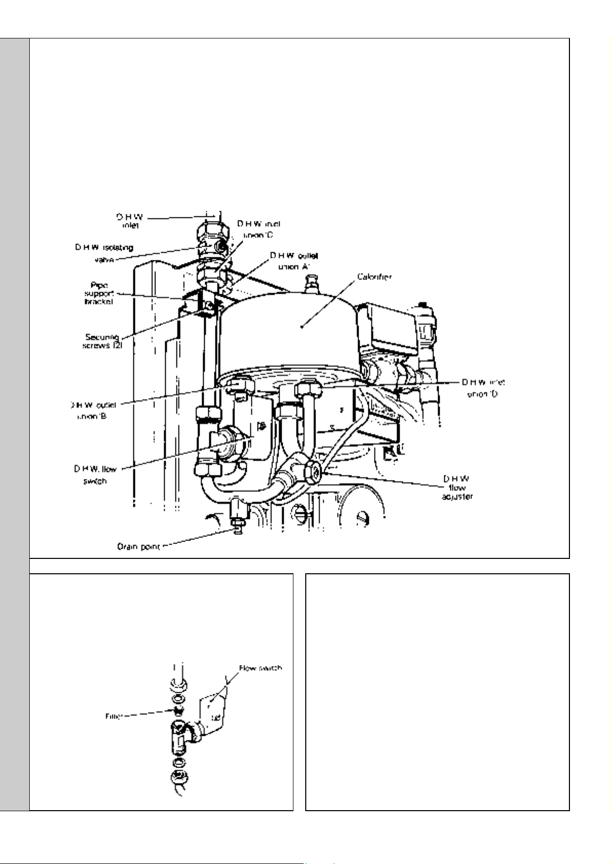
SERVICING
79
DHW FLOW SWITCH REPLACEMENT
1. Refer to Frame 64 (the Combi module cover only need be
removed).
2. Release the retaining screw and hang the CH expansion
vessel in the servicing position. Refer to Frame 45.
3. Disconnect the flow switch lead from the Logic PCB 27.
4. Remove the 2 securing screws and withdraw the pipe
support bracket.
5. Close the DHW isolating valve.
6. Open the lowest DHW draw-off tap.
7. Drain any residual water into a receptacle via the DHW
drain point.
8. Undo the DHW outlet pipe union nuts A & B and move the
pipe aside.
9. Undo the DHW inlet pipe union nuts C & D and withdraw
the switch assembly.
10. Transfer the pipes and DHW filter. Refer to Frame 80.
11. Fit the new flow switch complete with new sealing
washers, ensuring that the switch is fitted the right way
round. An arrow on the switch head indicates the
direction of flow (downward).
12. Re-assemble in reverse order.
SERVICING
80
DHW FILTER REPLACEMENT
1. Refer to Frame 64 (The Combi module cover only need
be removed).
2. Remove the DHW flow switch. Refer to Frame 79.
3. Prise the filter from
the housing in
the flow
switch inlet,
and clean
or renew as
necessary.
4. Reassemble in
reverse order.
81
DRAINING THE BOILER
IMPORTANT.
In order to replace the components in Frames 82 to 90 it is
necessary to drain the boiler.
Note. Refer to Frames 92 and 93 (Boiler and Combi
modules - exploded views) for illustration of the procedure
detailed below:
1. Refer to Frame 64.
2. Close the CH isolating valves.
3. Remove the heat exchanger drain plug, using a
Allen key, and drain the water into a suitable receptacle.
4. Refit the drain plug, using a suitable jointing compound.
5. In order to refill the boiler refer to Frame 4.
3/16"
40
Classic Combi FF 280 - Installation
Page 41

82
PRESSURE GAUGE REPLACEMENT
1. Refer to Frame 64.
2. Drain the boiler. Refer to Frame 81.
3. Release the retaining screw and hang the CH expansion
vessel in the servicing position. Refer to Frame 45.
4. Disconnect the pressure gauge capillary from the safety
valve.
5. Compress the 2 retaining lugs and withdraw the gauge
from the bracket.
SERVICING
6. Fit the new gauge and re-assemble in reverse order,
ensuring that:
83
CH EXPANSION VESSEL REPLACEMENT
1. Refer to Frame 64.
2. Drain the boiler. Refer to Frame 81.
3. Disconnect the flexible pipe from the vessel.
4. Release the retaining screw and withdraw the expansion
vessel.
5. Fit the new expansion vessel, complete with the new
sealing washer, and re-assemble in reverse order.
a. The capillary is carefully and neatly routed, as
previously.
b. The gauge is correctly orientated within the
housing.
SERVICING
Classic Combi FF 280 - Installation
41
Page 42
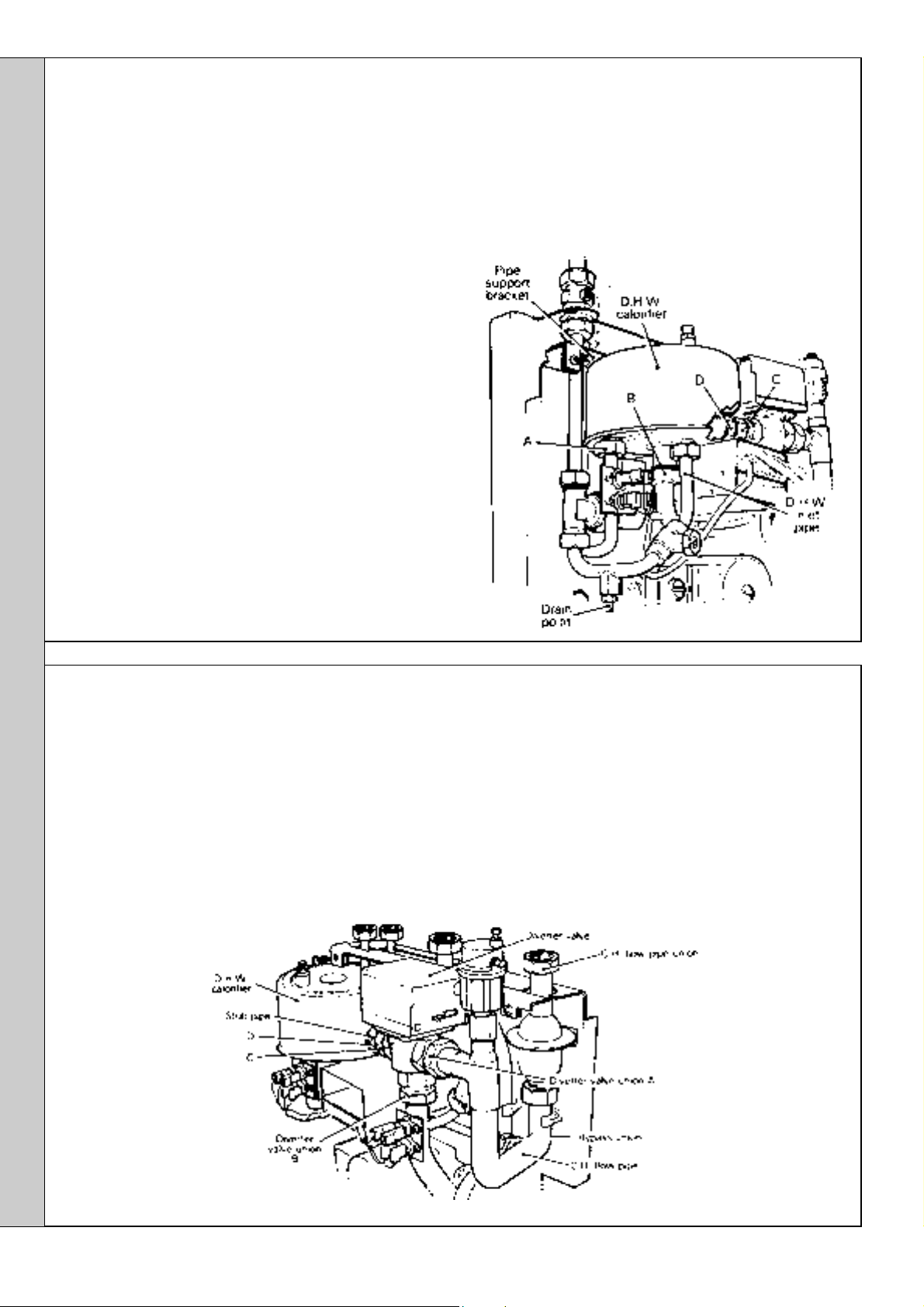
SERVICING
84
DHW CALORIFIER REPLACEMENT
1. Refer to Frame 64.
2. Drain the boiler. Refer to Frame 81.
3. Remove the CH expansion vessel. Refer to Frame 45.
4. Remove the 2 securing screws and withdraw the pipe
support bracket.
5. Close the DHW inlet isolating valve.
6. Open the lowest DHW draw-off tap.
7. Drain any residual water into a receptacle via the DHW
drain point.
8. Undo the unions on the DHW inlet pipe and move the pipe
aside.
9. Slacken diverter valve union nut C.
10. Undo calorifier union nut D.
11. Undo calorifier unions A and B and withdraw the calorifier
from the boiler.
12. Fit the new calorifier, complete with the new sealing
washers provided, and re-assemble in reverse order.
TO DESCALE THE CALORIFIER:
a. Remove the calorifier from the boiler as described
above.
b. Descale the domestic hot water coil, using a proprietary
descaling agent.
c. Rinse thoroughly with clean water.
d. Re-assemble in reverse order.
WARNING. The agents are highly corrosive - ingestion or
contact with skin, eyes and clothing MUST be avoided.
Protective clothing should be worn and the descaling
operation conducted out of doors in a well ventilated area.
Note. The names and addresses of suppliers of suitable
descaling agents are given in Frame 4.
SERVICING
85
DIVERTER VALVE (COMPLETE) REPLACEMENT
1. Refer to Frame 64.
2. Drain the boiler. Refer to Frame 81.
3. Remove the CH expansion vessel. Refer to Frame 45.
4. Remove the automatic air vent. Refer to Frame 88.
5. Disconnect the diverter valve lead at the inline connector.
6. Undo diverter valve union A and the bypass union.
7. Slacken the CH flow pipe union.
8. Undo diverter valve union B.
9. Slacken diverter valve union nut C as far back as possible.
10. Prevent union nut C from turning and undo calorifier union
nut D. This will jack the diverter valve towards the right
and permit its withdrawal from the boiler, complete with
stub pipe.
11. Transfer the stub pipe to the new valve.
12. Fit the new diverter valve and re-assemble in reverse
order.
42
Classic Combi FF 280 - Installation
Page 43

SERVICING
86
PUMP REPLACEMENT
1. Refer to Frame 64.
2. Drain the boiler. Refer to Frame 81.
3. Remove the CH expansion vessel. Refer to Frame 45.
4. Disconnect the pressure gauge capillary from the
safety valve. Refer to Frame 82.
5. Slacken the 2 securing screws and remove the CH
expansion vessel support bracket. Refer to Frame 45.
6. Remove the pump terminal box cover and disconnect
the electrical leads.
7. Slide the cable entry out and withdraw the cable from
the terminal box.
Note. If required, the PUMP HEAD ONLY may now be
replaced.
a. Remove the 4 socket screws and withdraw the
pump head.
b. Fit the new head and re-assemble in reverse order.
To remove the COMPLETE pump, proceed as follows:
8. Undo the boiler return elbow unions.
9. Undo the pump return union.
10. Swing the pump to disengage the boiler return pipe
from the clip and withdraw the pump, complete with
return pipe.
11. Undo the pump flow union and, using one of the new
gaskets provided, transfer the boiler return pipe to the new
pump.
12. Fit the new pump and re-assemble in reverse order,
ensuring that:
a. The new sealing gasket provided is fitted at the pump
return union.
b. The electrical connections are correctly remade. (Refer
to the diagram inside the terminal box cover).
c. The pump selector switch cover is correctly fitted and
that the switch is set at position 3.
87
SAFETY VALVE REPLACEMENT
1. Refer to Frame 64.
2. Drain the boiler. Refer to Frame 81.
3. Remove the CH expansion vessel. Refer to Frame 45.
4. Remove the 2 securing screws and withdraw the pipe
support bracket. Refer to Frame 45.
5. Disconnect the pressure gauge capillary from the safety
valve.
6. Disconnect the overflow
pipe at the bulkhead
fitting on top of the wall
mounting plate.
7. Undo the safety valve
union and withdraw the
valve, complete with the
overflow pipe.
Overflow pipe
union
SERVICING
8. Transfer the overflow pipe to the new valve, ensuring that
its orientation is the same as that of the previous
assembly (use the arrow engraved on the side of the
valve to aid realignment).
9. Fit the new safety valve, complete with the new sealing
washers provided, and re-assemble in reverse order.
Classic Combi FF 280 - Installation
43
Page 44

SERVICING
88
AUTOMATIC AIR VENT REPLACEMENT
1. Refer to Frame 64.
2. Drain the boiler. Refer to Frame 81.
3. Unscrew the automatic air vent from the boiler flow
header, applying an appropriate counter-force to the
boss, in order to prevent damage.
4. Fit the new air vent, using the 'O' ring provided, and reassemble in reverse order.
IMPORTANT. Ensure that the vent cap is loose.
89
CH THERMOSTATIC VALVE
REPLACEMENT
1. Refer to Frame 64.
2. Drain the boiler. Refer to Frame 81.
3. Remove the CH expansion vessel. Refer to Frame 45.
4. Remove the automatic air vent. Refer to Frame 88.
5. Remove the 2 securing screws and withdraw the pipe support
bracket. Refer to Frame 79.
6. Undo the diverter valve union A, the bypass union B and the
thermostat top union C.
7. Swing the flow pipe to the right to clear the diverter valve
union, unclip and withdraw the pipe, complete with thermostat.
8. Transfer the flow pipe to the new thermostat and re-assemble
in reverse order, using the new sealing washers provided.
SERVICING
90
BOILER HEAT EXCHANGER REPLACEMENT
IMPORTANT.
Before starting the removal procedure, protect the gas and
electrical controls with a waterproof sheet or similar.
Note. Refer to Frame 93 'Boiler Assembly - Exploded View'
for illustration of the procedure detailed below.
1. Drain the boiler.
2. Remove the CH expansion vessel. Refer to Frame 83.
3. Disconnect the electrical lead.
Remove the Combi module - following the procedure (in
reverse order) described in Frame 38.
Note. An extraction tool is provided (in the Hardware Pack)
to remove the push-fit brass elbow from the boiler and
Combi module.
4. Remove the burner / air box assembly. Refer to Frame 58.
5. Remove the fan assembly. Refer to Frame 73.
8. Slacken 3 turns only the 4 heat exchanger / inter-panel
retaining screws.
9. Lift the heat exchanger / inter-panel assembly upward and
forward to disengage key hole fixings. Pull the assembly
downward to clear the water pipes from the back panel.
10. Remove the 2 rubber sealing grommets from the top of the
back panel to facilitate fitting the new assembly.
11. Fit the new heat exchanger assembly, complete with water
pipes, and hang it on the key hole slots and screws.
12. Retighten the screws.
13. Replace the 2 rubber sealing grommets.
14. Re-assemble in reverse order.
6. Remove the combustion chamber by unscrewing the 4 tie
rods.
7. Remove the thermostat sensors from the pockets on the
heat exchanger.
44
15. Remake all water connections, ensuring that the
compression fittings (if used) are correctly refitted.
16. Fully test all functions, including water and gas soundness.
Classic Combi FF 280 - Installation
Page 45
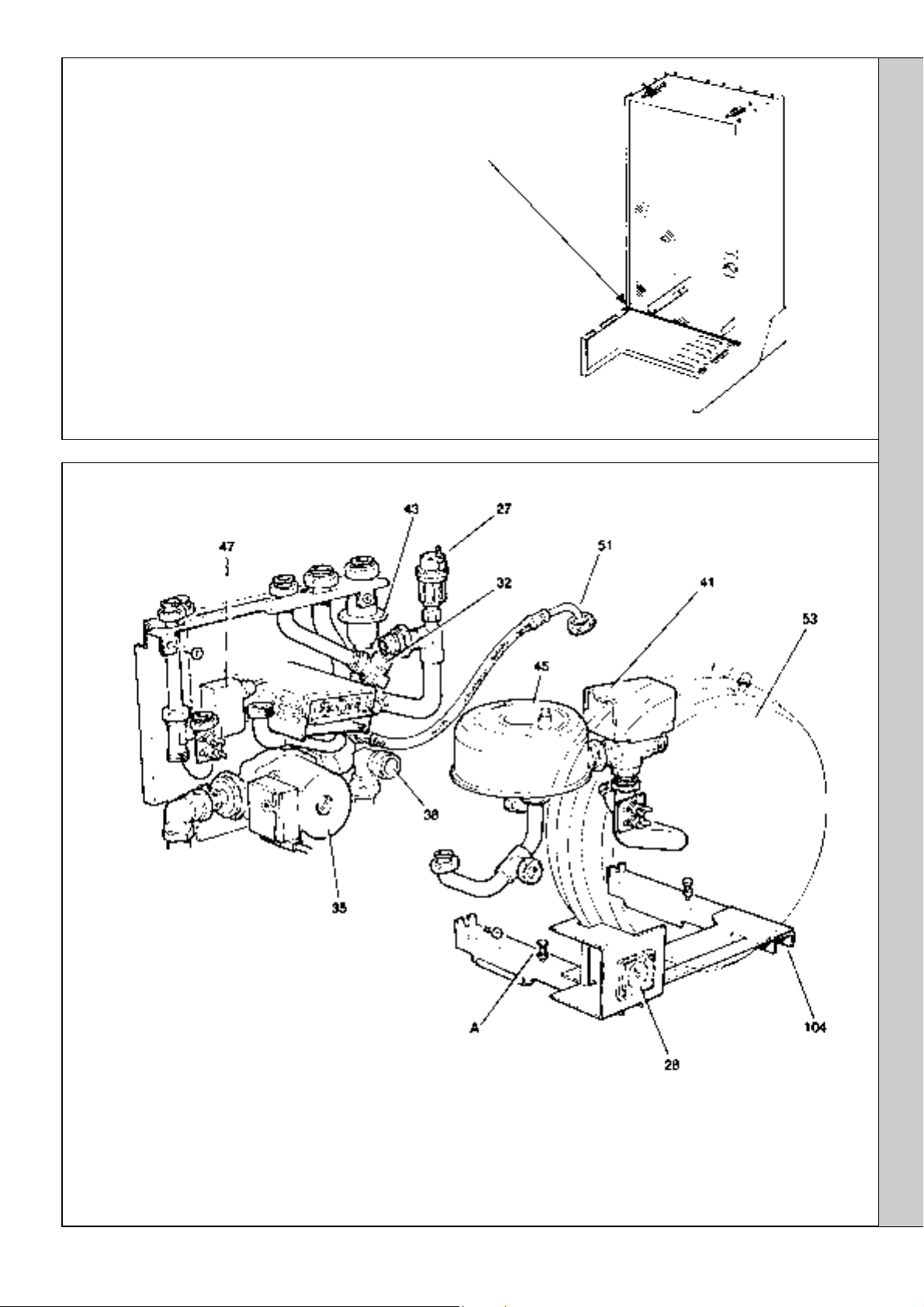
91
BOILER CASING SEAL REPLACEMENT
1. Refer to Frame 64.
2. Remove the old seal from the bottom edge of the casing and also
from the edges of the boiler back panel.
3. Fit the new self-adhesive seals.
INNER VIEW OF BOILER CASING
92
COMBI MODULE - Exploded View
SERVICING
LEGEND
27. Automatic air vent
28. Pressure gauge
32. Safety valve
35. Pump
38. Push-fit elbow
41. Diverter valve
43. CH thermostatic valve
SERVICING
51. Flexible hose
53. CH expansion vessel
45. Calorifier
47. DHW flow switch
104. CH expansion vessel support bracket
A. Pressure gauge height adjustment screws and locking nuts - 2 off.
Classic Combi FF 280 - Installation
45
Page 46
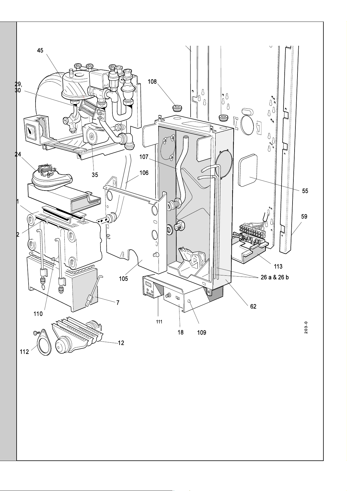
SERVICING
93
BOILER ASSEMBLY - Exploded View
SERVICING
LEGEND
1. Heat exchanger
2. Flue baffles
7. Combustion chamber
12. Main burner
18. Control box
24. Fan / collector hood assembly
26a & 26b. Pressure sensing pipes
29. CH control thermostat
30. DHW preheat thermostat
35. Pump
45. Calorifier
55. Sealing plates, 2 off
58. Wall mounting plate
59. Stand-off brackets (LH & RH side)
62. Back panel
100. DHW inlet isolating valve
101. DHW outlet connection
102. Safety valve drain connection
103. CH flow and return isolating
valves
105. Inter-panel
106. Pumped return pipe
107. Pumped flow pipe
108. Rubber sealing grommets
109. Overheat thermostat
110. Boiler drain point
111. Programmer (if fitted)
112. Burner support bracket
113. Terminal strip cover
46
Classic Combi FF 280 - Installation
Page 47
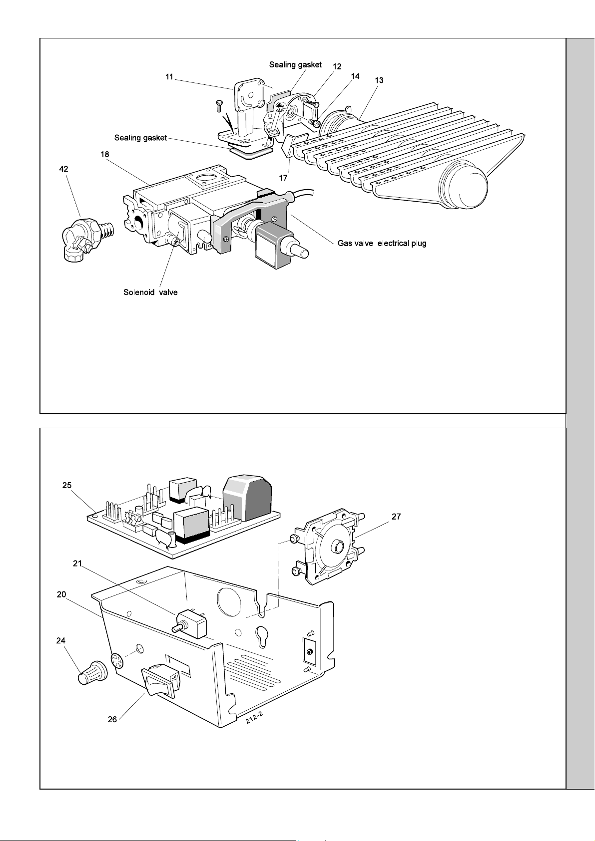
94
BURNER ASSEMBLY - Exploded View
SERVICING
LEGEND
(Numbers up to 67 relate to the B.G. spares list)
11. Burner manifold
12. Air box and pilot assembly
13. Main burner
14. Main burner injector
17. Pilot shield
18. Gas control valve
42. Gas service cock
95
CONTROL BOX - Exploded View
SERVICING
LEGEND
(Numbers up to 67 relate to
the B.G. spares list)
20. Control box
21. CH/HW switch
24. CH/HW switch knob
25. Printed circuit board
26. Mains on/off switch
27. Air pressure switch
Classic Combi FF 280 - Installation
47
Page 48

FAULT FINDING
Before attempting to rectify any electrical fault ALWAYS carry out the preliminary electrical system checks, using a suitable test
meter. Detailed instructions on the replacement of faulty parts are contained within the 'Servicing' section of this publication.
Notes.
1. Ensure that the boiler and system is full of water, free from air locks and that the pump is running.
2. Press the overheat thermostat reset button and continue with the fault finding procedure. Replace the thermostat if it operates
before the normal working temperature is reached.
3. In order to assist fault finding, the control box printed circuit board is fitted with 4 indicator lights:
Neon I
1
Neon I
2
Neon I
3
Neon SGI Flashes to indicate spark operation (stops after detection)
96
DOMESTIC HOT WATER MODE Start from cold. Turn the CH / HW switch to HW ONLY and the
Is there a
supply voltage
at the mains
input terminal
strip?
Expect 230 V
AC +10% -6%
NO
Check all
fuses
FAULT FINDING
Air pressure switch made
Fan voltage indication
Mains supply to PCB 25B.
YES
Switch OFF
THEN
the mains
supply,
disconnect
the DHW
preheat
thermostat
Replace the
switch
Replace the
thermostat
Replace the
thermostat
Replace the
flow switch
Switch ON the
mains supply
and fully open
Does neon I
No.25B glow ?
NO
NO
NO
NO
Has the DHW
Replace Logic
a DHW tap.
on PCB
NO
Has the
burner on/off
switch made
contact ?
YES
Is the DHW
thermostat
calling for
heat ?
YES
Is the DHW
overheat
thermostat
calling for
heat?
YES
flowswitch
operated ?
YES
PCB No.27
burner ON/OFF switch to ON. Also turn any time clock ON and
switch ON the mains electricity supply.
YES
Does the
pump start ?
3
NO
Is there a
supply
voltage at
the pump ?
Expect
230 V AC
+10% -6%
NO
Check that
the pump
is free to
rotate.
Does the
pump now
start ?
Replace
the pump
YES
NO
YES
Does neon I
on PCB
No.25B glow?
Is the air
pressure
switch in the
NC position at
the start of the
ignition
sequence ?
Does the
fan start ?
Replace the
air pressure
Does neon I
now glow ?
Replace automatic
ignition PCB
No. 25B
NO
switch
NO
NO
NO
2
2
NO
YES
Does neon I
on PCB
No.25B glow ?
NO
Does the
fan start ?
Is there a
supply voltage
to the fan ?
(230 V
+10% -6%)
YES
Replace the
fan
NO
YES
1
YES
48
Classic Combi FF 280 - Installation
Page 49

Has the air
pressure
switch
operated ?
NO
Is the
boiler
casing
correctly
fitted ?
YES
Check the
sensing
pipes for
blockage
and bad
connections.
Does the
air
pressure
switch now
operate ?
NO
Replace
the
pressure
switch
Is
YES
there a
good
spark
at the
pilot ?
NO
Is there a regular
flash from the tube
on the auto ignition
PCB No. 25B ?
YES
Refer to
Frame 68.
Check the gap
between the
electrode and
hood. Check
that the HT
lead and
electrode are
undamaged
and that
connections
are not close to
earthed
metalwork
Does
the pilot
light ?
Is there
a gas
supply
to the
pilot ?
NO
YES
Does the
spark
stop after
the pilot
has lit ?
Replace
automatic
ignition
PCB
No. 25B
YES
Is the pilot
injector
free from
blockage?
YES
Is there a
supply voltage
at the pilot
valve
terminals ?
(230 V AC
+10% -6%)
YES
NO
Replace
the gas
control
valve
FAULT FINDING
YES
Does the
main
burner
cross-light
from the
pilot ?
NONO
NO
Is there a
voltage at the
main gas
valve? (230 V
AC
+10% -6%)
YES
Replace
the gas
control
valve
YES
NO
Is the
MAXIMUM
burner
pressure
attained ?
NO
Is there a
voltage at the
bypass valve
GV
? (230 V
3
AC
+10% -6%)
NO
Check that the
DHW draw-off rate
is greater than
6.5 l/min. Is there
now a voltage at
gas valve GV
NO
Replace
Logic PCB
No.27
YES
?
3
YES
Replace
the gas
control
valve
Replace the
DHW control
thermostat
Does the
burner
pressure
reduce to
minimum
setting, in
response to
an increase
in the
Domestic
Hot Water
temperature,
when the
rate is
reduced to
less than
6 l/min ?
NO
YES
The boiler is
operating
correctly
Classic Combi FF 280 - Installation
FAULT FINDING
49
Page 50

FAULT FINDING
97
PREHEAT MODE
Start from cold. Turn the CH/HW switch to HW ONLY and any time clock ON. Ensure that all DHW taps are OFF.
Turn the burner on/off switch ON. Switch ON the mains supply.
Is there a supply
voltage at the
mains input
terminal strip ?
(Expect 230 V
AC +10 -6%)
NO
Check all fuses
Replace the
switch
Replace the
thermostat
YES YES
Does the neon I
on PCB No.25B
NO
Has the burner
made contact ?
NO
glow ?
on/off switch
Is the DHW overheat
thermostat calling for
3
NO
YES
heat ?
Does the
pump start ?
Is there a
supply
voltage at
the pump ?
(Expect 230
V AC +10%
-6%)
YES
NO
YES
Does
neon I
2
glow ?
NO
Is the air
pressure
switch in the
NC position at
the start of the
ignition
sequence ?
NO
Does the
fan start ?
NO
YES
Does
neon I
1
glow ?
NONO
Does the
fan start ?
NO
YES
YES
Has the air
pressure switch
operated ?
NO
Is the boiler
casing correctly
fitted ?
YES
Replace the
thermostat
NO
YES
Is the DHW preheat
thermostat calling for
heat ?
YES
Replace the Logic
PCB No.27
Check that
the pump is
free to
rotate. Does
the pump
now start ?
NO
Replace the
pump
Replace the air
pressure switch
Does neon I
now glow ?
NO
2
NO
Check the
sensing pipes
for blockage
and bad
connections.
Does the air
pressure switch
now operate ?
NO
Replace the
pressure switch
Is there a
supply
voltage to
the fan ?
(230 V
+10% -6%)
YES
FAULT FINDING
50
Replace
the fan
Replace
automatic ignition
PCB No. 25B
Classic Combi FF 280 - Installation
Page 51

FAULT FINDING
Is there a
good spark
at the pilot ?
Is there a
regular flash
from the
tube on
automatic
ignition PCB
No.25B ?
YES
Refer to
Frame 68.
Check the
gap between
the
electrode
and hood.
Check that
the HT lead
and
electrode
are
undamaged
and that
connections
are not close
to earthed
metalwork
NO
Does the
pilot light ?
NO
Is there
a gas
supply
to the
pilot ?
YES
Is the pilot
injector
free from
blockage ?
YES
Is there a
supply
voltage at
the pilot
valve
terminals ?
(230 V AC
+10% -6%)
NO
YESYES
YES
Replace the
gas control
valve
Does the
spark stop
after the pilot
is lit ?
NONO
Replace
automatic
ignition
PCB
No.25B
Replace the
thermostat
YES YES
NO
Does the main
burner cross-
light
from the pilot ?
NO
Is there a
voltage at the
main gas
valve ?
(230 V AC
+10% -6%)
YES
Is the DHW
preheat
thermostat
calling for heat?
YES
Replace the
gas control
valve
Is the
MINIMUM
burner
pressure
attained ?
NO
Is there a
voltage at
the bypass
valve GV
(Expect
zero)
YES
Replace
Logic PCB
No.27
Does the burner
YES
?
3
Replace the
DHW preheat
thermostat
extinguish after
approx 3
minutes, in
response to
increased boiler
temperature ?
NO
The boiler is
operating
correctly
YES
Classic Combi FF 280 - Installation
FAULT FINDING
51
Page 52
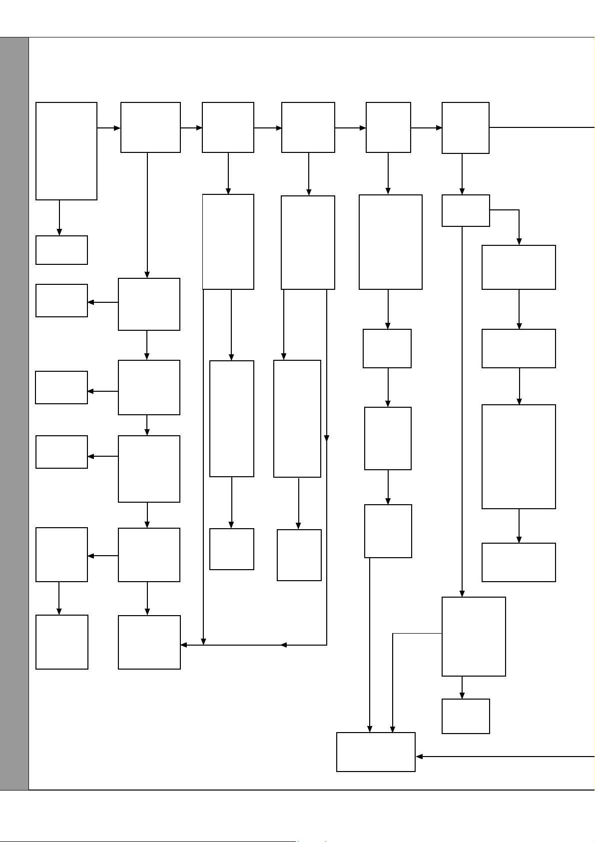
FAULT FINDING
98
CENTRAL HEATING MODE
Start from cold. Turn the CH/HW switch to CH & HW, and any time clock and room thermostat ON.
Ensure that all DHW taps remain OFF. Turn the burner ON/OFF switch ON. Switch ON the mains supply.
Is there a
supply
voltage at the
mains input
terminal
strip? (Expect
230 V AC
+10% -6%)
NO
Check all
fuses
Replace
the switch
Replace
the switch
Replace the
thermostat
Can the
thermostat
be reset ?
YES
NO
NO
NO
YES
Does neon I
on PCB
No.25B glow?
NO
Has the
burner on/off
switch made
contact ?
YES
Has the
CH / HW
switch made
contact ?
YES
Is the CH
control
thermostat
calling for
heat ?
YES
Has the
overheat
thermostat
operated?
3
YES
Does the
pump
start ?
NO
Is there a
supply
voltage at
the pump?
(Expect 230
V AC
+10% -6%)
NO YES
Check
that the
pump is
free to
rotate.
Does the
pump
now
start ?
NO
Replace
the pump
YES
Does the
diverter
valve
operate ?
Is there a
supply
voltage at
the valve?
(Expect 230
V AC
+10% -6%)
YES NO
Check
that the
manual
lever is
free to
move.
Does the
valve now
open?
NO
Replace
the valve
actuator
NO
Does
neon I
2
glow ?
NO
Is the air
pressure
switch in the
NC position
at the start of
the ignition
sequence ?
NO
Does the
fan start ?
NO
Replace
the air
pressure
switch
Does
neon I
2
now
glow ?
NO
YESYES
Does
neon I
glow ?
NO
Does the
fan start ?
NO
YES
1
YES
Has the air
pressure switch
operated ?
NO
Is the boiler
casing correctly
fitted ?
YES
Check the
sensing pipes
for blockage
and bad
connections.
Does the air
pressure switch
now operate ?
NO
Replace the
pressure switch
NO
Replace
the
thermostat
FAULT FINDING
52
NO
Replace
Logic PCB
No.27
NO
Replace
automatic ignition
PCB No. 25B
Classic Combi FF 280 - Installation
Is there a
supply voltage
to the fan ?
(Expect 230 V
AC
+10% -6%)
YES
Replace
the fan
Page 53

FAULT FINDING
Is there a
good spark
at the pilot ?
NO
Is there a
regular flash
from the
tube on
automatic
ignition PCB
No.25B ?
NO
YES
YES YES YES
Does
the pilot
light ?
NO
Is there
a gas
supply
to the
pilot ?
YES
Is the pilot
injector
free from
blockage ?
YES
Does the
spark stop
after the
pilot is lit ?
NO
Replace
automatic
ignition
PCB
No.25B
YES
NO
Does the
main burner
cross-light
from the
pilot?
Is there a
voltage at
the main gas
valve ?
(230 V AC
+10% -6%)
Replace
the gas
control
valve
NO
YES
YES
Is the
MAXIMUM
burner
pressure
attained ?
NO
Is there a
voltage at
the bypass
valve GV
(Expect
230 V AC
+10% -6%)
NO
Replace
Logic PCB
No.27
Does the
boiler flow
temperature
rise to
approx
0
60
C
before
allowing
hot water
to the
system
?
3
(approx.10
mins.)
NO
Replace the
thermostatic
valve
Does the
burner
extinguish
in
response
to an
increase
in CH
temp-
erature?
NO
YES
Refer to
Frame 68.
Check the
gap between
the
electrode
and hood.
Check that
the HT lead
and
electrode
are
undamaged
and that
connections
are not close
to earthed
metalwork
YES
Is there a
supply
voltage at
the pilot
valve
terminals?
(230 V AC
+10% -6%)
YES
NO
Replace the
gas control
Replace the
CH control
thermostat
valve
Classic Combi FF 280 - Installation
The boiler is
operating
correctly
FAULT FINDING
53
Page 54

SHORT LIST OF PARTS
The following are parts commonly required due to damage or
expendability. Their failure or absence is likely to affect safety
or performance of this appliance.
The list is extracted from the British Gas List of Parts, which
contains all available spare parts.
The full list is held by British Gas, Caradon Ideal distributors
and merchants.
Key No. GC Part No. Description Qty. Product No.
8 308 365 Sightglass assembly kit 1 079 602
12 379 919 Main burner: AEROMATIC No. AC 19/123 292 1 111 709
13 398 065 Main burner injector: BRAY Cat. 10 - size 2300; 1 004 444
14 397 943 Pilot burner injector: HONEYWELL 4580 1 004 982
14A 308 358 Pilot burner: HONEYWELL Q359 A 1124 1 079 599
16 -- Gas control valve: HONEYWELL VR 4601 PA 2020 1 111 075
17 308 536 Ignition electrode complete with lead and backnut 1 111 881
18 -- Control box assembly 1 150 615
Classic Combi FF 280
Gas Boilers
When ordering spares please quote:
1. Boiler Model
2. Appliance G.C. Number
3. Description
4. Quantity
5. Product Number
19 374 073 Rotary on/off switch 1 005 823
21 386 149 Automatic ignition printed circuit board - PACTROL PCB No. 25B 1 079 716
22 386 802 Burner on/off switch:
ARROW HART Cygnet Series No. 100 0 11 E (A) 1 004 882
23 -- Pressure switch: HONEYWELL YAMATAKE C6065 A 1010 1 137 990
24 308 536 Fan assembly 1 111 947
27 386 830 Automatic air vent: CALEFFI 5030 1 113 116
28 374 088 Pressure gauge 1 113 089
29 392 921 Thermostat - high setting 1 079 634
30 378 074 DHW preheat thermostat:
ELMWOOD 2455 R - 192 / 940 (green dot) 1 079 635
31 378 075 DHW control thermostat
ELMWOOD 2455 R - 192 / 941 (yellow dot) 1 079 636
32 374 045 Safety valve: CALEFFI 3141 1 113 026
33 374 074 Combi module cover (with fixing screw) 1 079 637
35 374 076 Pump: GRUNDFOS 15 - 50 1 005 595
41 374 081 Diverter valve assy: HONEYWELL 4044 C 1536 1 005 871
43 374 083 CH thermostatic valve 1 005 803
47 374 086 DHW flow switch assy: HONSBERG Fluvatest UM 15 MA 1 005 856
48 378 085 DHW filter: GASCON G - C 901 1 005 810
52 378 076 Logic PCB No.27, PACTROL 1 005 632
53 374 100 CH 8 -litre expansion vessel 1 113 205
54 -- Boiler casing assembly 1 079 947
56 -- Controls casing door 1 079 948
57 308 331 Boiler sealing pack 1 079 605
67 378 087 CH overheat thermostat, RANCO LM7 - P 8508 1 005 900
54
Classic Combi FF 280 - Installation
Page 55

99
SHORT PARTS LIST
SHORT LIST OF PARTS
Classic Combi FF 280 - Installation
55
Page 56
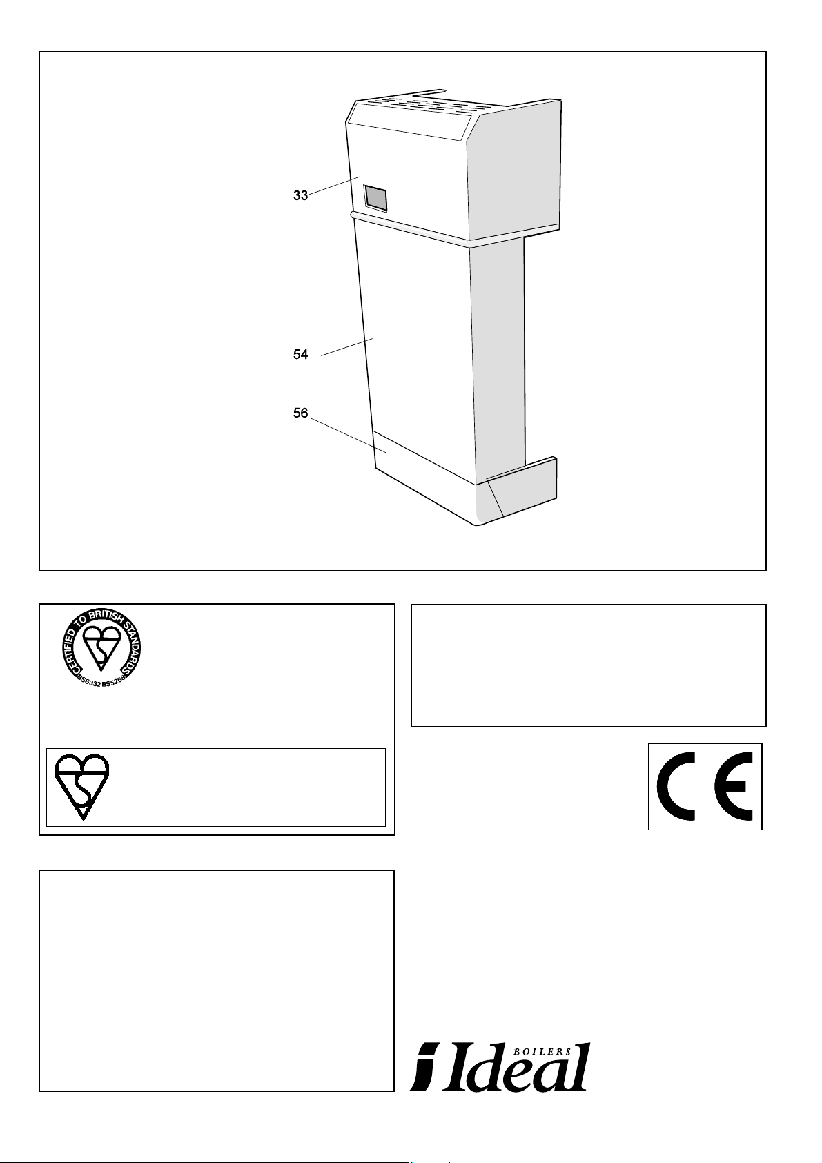
100
BOILER CASING ASSEMBLY
THIS SYMBOL IS YOUR
ASSURANCE OF QUALITY
These appliances are designed for use with Natural
Gas only. They have been tested and conform with
the provisions of BS. 6332 and BS. 5258.
CERTIFIED PRODUCT
Manufactured under a BS EN ISO 9001:1994
Quality System accepted by BSI.
Customer Care & Technical Support
Please use the following numbers for speedy assistance.
Ideal Parts ................................... Tel: 01482 498 665
................................................... Fax: 01482 498 489
Customer Care & Technical Support.
Scotland/N. England/Midlands ..... Tel: 01482 498 636
Southern England/S. Wales ......... Tel: 01482 498 660
................................................... Fax: 01482 498 666
Technical Training
The Caradon Ideal Technical Training Centre offers a series
of first class training courses for domestic, commercial and
industrial heating installers, engineers and system specifiers.
For details of courses please ring:
............................... Alexa Beadle on 01482 498 432
CARADON IDEAL Ltd. pursues
a policy of continuing
improvement in the design and
performance of its products. The
right is therefore reserved to vary
specification without notice.
CE NO. FF.87/AQ/41
CARADON IDEAL Ltd.,
P.O. Box 103, National Avenue,
Kingston upon Hull, HU5 4JN.
Telephone: 01482 492 251 Fax: 01482 448 858.
Registration No. London 322 137.
Registered Office; National Avenue,
Kingston upon Hull, HU5 4JN.
A subsidiary of Caradon p.l.c
March 1997 112 228 A05
Publications/literature. ............... Tel: 01482 498 467
Printed in England
 Loading...