

Page 1
WARNING!
1. DO NOT UNDER ANY CIRCUMSTANCES EXCEED
THESE RATINGS:
-Voltage is not to exceed 600V AC or DC.
- Resistance, Capacitance, Logic, and Continuity
functions are not to be performed on circuits capable
of delivering greater than 500V AC or DC.
-Current measurements are not to be performed on
circuits capable of delivering greater than 600V AC
on insulated conductors, 250V AC on uninsulated
conductors.
2. To avoid electrical shock hazards and/or damage to the
meter:
- Do not exceed the voltage ratings for the meter. Use
caution when measuring voltage.
-Do not use during electrical storms. AC power
sources with inductive loads or electrical storms may
result in high voltage. High energy transients can
damage meter and present a dangerous shock hazard.
-Turn off the power to the circuit or device being mea-
sured before taking resistance and capacitance mea-
surements. Fully discharge all capacitors before
measuring.
3. Ensure meter is in proper working order before using.
Visually inspect meter for damage. Performing a conti-
nuity check can verify proper operation. If the meter
reading goes from overload to zero, this typically means
the meter is in proper working order.
4. Visually inspect leads for damage before using. Replace
if insulation is damaged or leads appear suspect.
5. Never ground yourself when taking electrical measure-
ments. Do not touch exposed metal pipes, outlets, fix-
tures, etc. Keep your body isolated from ground by
using dry clothing, rubber shoes, rubber mats, or any
other approved insulating material. Keep your fingers
behind the finger guards on the probes. Work with oth-
ers.
6. Before beginning all unknown measurements, set meter
to the highest range possible.
Page 2
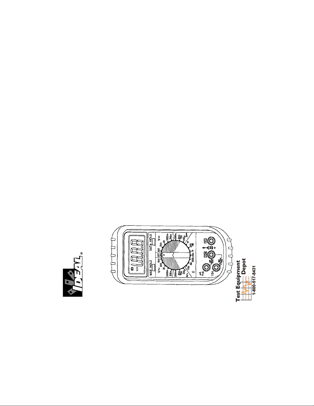
#61-360
IDEAL Test Pro
®
360 Series Multimeter
99 Washington Street
Melrose, MA 02176
Fax 781-665-0780
TestEquipmentDepot.com
Page 2
AC VOLTAGE
Meter Setup: Circuit Connection:
Function Range Resolution Accuracy
AC Voltage 200.0 mV .1 mV
2000 mV 1mV 50 to 500Hz
20.00 V .01 V
≤ 20 V range ±(1% +4)
200.0 V .1 V ≤ V range ±(1.5% +4)
600 V 1 V
To Measure DC Voltage
1. Plug the test leads into meter inputs as indicated in the dia-
gram on the next page.
2. Select the proper range to be used within the VDC area.
4. Connect the meter in parallel with the load or circuit.
5. Measure DC voltage.
DC VOLTS
Meter Setup: Circuit Connection:
Page 4Page 3
WARNING! (cont.)
7. Before breaking a circuit for testing, turn off the power to
the circuit. When disconnecting from a circuit, discon-
nect the hot lead first, then the common lead.
8. Disconnect the meter from the circuit before turning off
any indicator, including motors, transformers,and sole-
noids.
Overload Protection
V
AC
+ V
DC
200mV range 500VDC/350VAC
for 15 sec
>200mV range 600VDC/600VAC
A
AC
+ A
DC
mA input 0.5A/250V
10A input 10A/600V
Ohms (Ω)500VDC/500VAC
Diode 500VDC/500VAC
Continuity 500VDC/500VAC
Unit of Measure Multipliers
For your reference, the following symbols are often used to
make measurement easier:
Symbol Verbal Multiplier
MmegaX1,000,000
KkiloX1,000
mmilli÷1,000
µmicro÷1,000,000
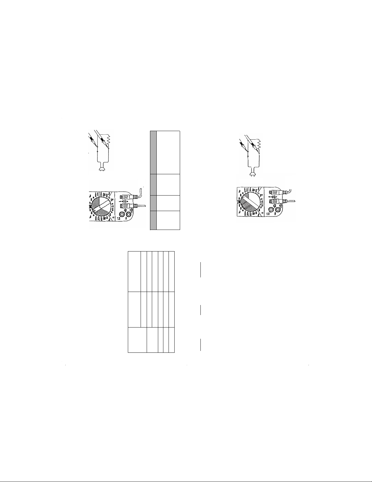
To Measure AC Voltage:
1. Plug the test leads into the meter inputs as indicated in
the diagram below.
2. Select the proper range to be used within the VAC area.
3. Connect the meter in parallel with the load or circuit.
4. Measure AC voltage.
Red
Black
Red
Black
Page 3
Page 5
Page 6
Function Range Resolution Accuracy
DC Voltage 200.0 mV .1 mV ± (0.5% +1)
2000 mV 1 mV ± (0.5% +1)
20.00 V .01 V ± (0.5% +1)
200.0 V .1 V ± (0.5% +1)
600 V 1 V ± (0.5% +1)
To Me as ure R es is tan ce :
Resistance is measured in Ohms.
1. Turn the power off to the circuit or device that is to be mea-
sured and discharge all capacitors before measurement is
to be taken.
2. Plug test leads into the meter inputs as indicated in the
following diagram.
3. Select the proper range within the Ω function of the tester.
4. Measure resistance. If necessary, perform the required
multiplication to acquire the actual resistance.
4.1 Range Guide for Ohms (Ω):
200 = Meter indicates actual resistance
2K = Multiply meter display reading by 1,000 to
acquire actual resistance.
20K = Multiply meter display reading by 1,000 to
acquire actual resistance.
200K = Multiply meter display reading by 1,000 to
acquire actual resistance.
2M = Multiply meter display reading by
1,000,000 to acquire actual resistance
200M = Multiply meter display reading by
1,000,000 to acquire actual resistance.
5. The meter displays total resistance through all possi-
ble paths between the probe-tips. These multiple
paths may result in measurements that do not corre-
spond to the ohm value indicated by the resistor
color code.
Resistance (Ohms)
Meter Setup: Circuit Connection:
Function Range Resolution Accuracy
Resistance 200.0Ω .1Ω ±(1.0% + 4)
2.000KΩ .001KΩ ±(1.0% + 4)
20.00KΩ .01 KΩ ±(1.0% + 4)
200.0KΩ .1KΩ ±(1.0% + 4)
2.000MΩ .001MΩ ±(1.0% + 4)
20.00MΩ .01 MΩ ±(2.0% + 4)
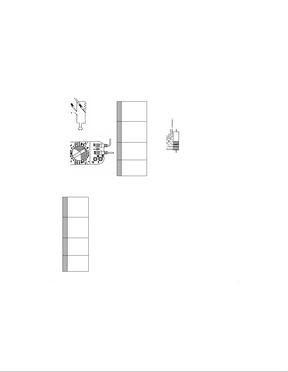
Determining Resistor Values:
To d et er mi ne t he v al ue o f a r es is to r, us e t he c ol or b an ds on t he
resistor and the following table.
Red
Black
Test Equipment Depot - 800.517.8431 - 99 Washington Street Melrose, MA 02176
FAX 781.665.0780 - TestEquipmentDepot.com
Page 4

To Verify Continuity:
4. Test for continuity by connecting the meter to the circuit.
5. If the beeper sounds the circuit is complete.
Continuity Beeper
(beeps at resistance <30
Ω
)
Meter Setup: Circuit Connection:
Diode Testing:
To e ns ur e a pr op er f un ct io ni ng di od e, t he m et er wi ll d ev el op a
voltage across the component from a test current. The diode
test function allows measurements of forward voltage drops
across diodes and transistor junctions.
1. Turn off power to the device or circuit that is being tested
and discharge all capacitors.
2. Plug the leads into the meter inputs as indicated in the fol-
lowing diagram.
3. Select the diode function on the meter.
4. Connect the red rest probe to the anode (+) and the black
test probe to the cathode (-) of the diode. If the diode is
shunted by a resistor of 1K Ohm or less, it must be
removed from the circuit before taking the measurement.
Page 8
Page 7
Resistor Color Code Table
1st 2nd Tolerance
Color Digit Digit Multiplier (Percentage)
Black 0 0 1
Brown 1 1 10
Red 2 2 100
Orange 3 3 1,000
Yel low 4 4 10 ,00 0
Green 5 5 100,000
Blue 6 6 1,000,000
Violet 7 7 10,000,000
Gray 8 8 100,000,000
White 9 9 1,000,000,000
Gold +/- 5%
Silver +/- 10%
No Color +/- 20%
Example:
1st color band is blue so the first digit is a 6
2nd color band is red so the second digit is a 2
3rd color band is yellow so multiply 62 x 10,000
4th color band is gold so the tolerance is ±5%
You r R esi sto r valu e is 620 ,00 0 O hms ( 620 KΩ)with a tolerance
of ±5%.
To Verify Continuity:
A continuity test ensures that all circuit connections are intact.
1. Plug the test leads into the meter inputs as indicated in the
diagram below.
2. Turn the power off to the circuit or device that is to be veri-
fied.
3. Select the continuity function on the meter. See
switch position below. The continuity function is located at
the 200Ω setting.
Blue
Red
Yellow
Gold
Red
Black
Page 5

Page 10Page 9
5. Read the forward voltage drop on the digital display:
5.1 A good silicon diode will result in a reading around
0.7 V.
5.2 A good germanium diode will result in a reading
around 0.3 V.
5.3 A short is indicated by a continuous beep and a
reading of .000 V.
5.4 An open is indicated by a 1. V reading.
6. Reverse the test probe connections to the diode and per-
form a reverse-leakage test of the diode.
6.1 A reading of 1. V indicates reverse blocking and a
good diode.
6.2 A reading of .000 V and a continuous beep indicates
high reverse leakage current or a short.
DIODE TESTING
Meter Setup: Circuit Connection:
Function Range Resolution Accuracy
Diode Test 3 VDC 1 mV ± (1.5% + 1)
To Measure AC Current:
Current is measured in amps.
Do not attempt to measure current in circuits capable of deliv-
ering greater than 600V. If the current is unknown, begin at the
highest range, selecting the next lowest until a reading is dis-
played.
To Measure AC Current (cont.):
1. Connect the test leads into the meter inputs as indicated in
the following diagram.
2. Select the proper range to be used within the AAC area.
3. Turn the power off.
4. Connect the meter in series with the load or circuit.
5. Turn power on.
6. Measure AC Current.
Meter Setup:
Current <200mA AC Current AMPS>200mA AC
10 Amps Max.
Circuit Connection:
Function Range Resolution Accuracy
AC Current 200.0µA .1µA ±(1.5% + 4)
20.00 mA .01 mA ±(1.5% + 4)
200.0mA .1mA ±(1.5% + 4)
20.00A .01A ±(2.5%)
Red
Black
Red
Black
Red
Black
Page 6

Page 12
Page 11
To Use Accessories:
For AC Current Clamp:
1. Plug test leads into the meter inputs as indicated in dia-
gram 1.
2. Remove the probe tips from the end of the leads.
3. Attach the leads to the current clamp (polarity will not affect
reading).
4. Select the mVAC range on the meter.
5. Snap the jaw of the current clamp around one of the current
carrying conductors.
6. Take reading.
For all other Accessories:
1. Plug test leads into the meter inputs as indicated in dia-
gram 2.
2. Remove the probe tips from the end of the leads.
3. Attach the leads to the accessory.
4. Select the mVDC range on the meter.
5. Turn the accessory on.
6. Take reading.
Diagram 1 Diagram 2
To Measure DC Current:
Current is measured in amps.
Do not attempt to measure current in circuits capable of
delivering greater than 600V. If the current is unknown,
begin at the highest range, selecting the next lowest until a
reading is displayed.
1. Plug the test leads into the meter inputs as indicated in
the following diagram.
2. Select the proper range to be used within the ADC area.
3. Turn power off.
4. Connect the meter in series with the load or circuit.
5. Turn power on.
6. Measure DC Current.
Meter Setup:
Current <200mA DC Current >200mA DC
10 Amps Max.
Circuit Connection:
Function Range Resolution Accuracy
DC Current 200.0µA .1µA ± (1.0% +1)
20.00 mA .01 mA ± (1.0% +1)
200.0mA .1mA ± (1.0% +1)
20.00A .01A ± (2.0% +3)
Red
Red
Black
Black
Red
Black
Red
Black
Page 7

Page 14
Page 13
Cleaning Case and window
Periodically wipe the case with a damp cloth and detergent,
allow to dry completely before using; do not use abrasives or
solvents.
Battery Replacement
When the multimeter displays the the battery must be
replaced to maintain proper operation.
WARNING
To p re ve nt e le ct ri ca l sh oc k ha za rd , t ur n of f th e m ul ti me te r an d
disconnect test leads before removing the back cover.
1. Disconnect the test leads and turn the meter off. Remove
the test leads from the front terminals.
2. Position the meter face down. Remove the screws from the
case bottom.
3. Lift the end of the case back until it gently unsnaps.
4. Lift the battery from the case back.
5. Replace battery.
6. Replace the case top. Reinstall screws.
Tro ub le sho ot ing :
The meter has been designed to be accurate, reliable and easy
to use. However, it is possible that you may experience diffi-
culties during operation. If there appears to be any kind of
problem during use of the multimeter, please perform the fol-
lowing steps to help determine the source:
1. Review and comply with the operating instructions section
of this instruction manual.
2. Test the battery, replace as necessary.
3. Test the fuses, replace as necessary.
4. Check to see that the Function/Range Switch is in the cor-
rect position for the type of parameter and range of values
being measured, and that the measurement value is within
the capability of the multimeter.
5. Inspect the test leads for breaks or cracks, and ensure that
the test leads are inserted fully into the input connectors.
6. If problem persists, meter should be inspected by a quali-
fied service person.
General Specifications:
Data Hold: “HOLD” button “locks” reading. Any range or func-
tion.
Max hold: “Max” button locks the largest reading. Any range,
any function.
Low battery indicator: Located in the LCD.
Indicators: Continuity Beeper: (<30Ω <500msec, 3V type),
low battery, polarity. Overrange: “OL” is displayed.
Environmental: Operating temperature 32°F to 122°F, storage
0°F to 140°F with batteries removed, RH<70%.
Tem pe ra tu re Co ef fi ci ent : 0.05 x (accuracy) per °F (32°F to
65°F, 80°F to 122°F)
Measurement rate: 2.5 times/sec.nominal.
Battery life: >300 hours typical with carbon-zinc battery.
Battery type: 9V NEDA 1604 type.
Safety: Designed to IEC1010-1 Cat. III 600V, UL1244.
Overload Protection: 600V for VAC, VDC. 500V for resis-
tance. Current protected by 0.5A/250V (5x20mm) fuse model
LA-3895 and 10A/600V (6.35x25.4mm) fuse model LA-3897.
Fuse Replacement
1. Disconnect the test leads and turn the meter off. Remove
the test leads from the front terminals.
2. Position the meter face down. Remove the screws from the
case back.
3. Lift the end of the case back until it gently unsnaps.
4. Remove the fuse by gently prying one end of the fuse loose
and sliding the fuse out of the bracket.
5. Verify continuity across the fuse.
6. If the fuse is good, return to tester.
7. If the fuse is blown, install a new fuse of the same size and
rating.
8. Replace the case top. Reinstall screws.
User Maintenance
Regular operator maintenance of the multimeter consists of
cleaning case and window, and battery replacement. All other
repairs must be performed by a factory service center or other
qualified instrument service personnel.
Test Equipment Depot - 800.517.8431 - 99 Washington Street Melrose, MA 02176
FAX 781.665.0780 - TestEquipmentDepot.com
 Loading...