

ICT ICT240DB-8IRC Instruction Manual

Innovative Circuit
Technology Ltd.
Front Access Distribution
Panel Series
INSTRUCTION MANUAL
855-154-000
Model: ICT240DB-8IRC

2 Innovative Circuit Technology Ltd.
WARNING
Risk of serious personal injury or damage to equipment and property! Always
observe the following:
Use an appropriately rated over-current protection device in line with the
main battery connections to the panel
Use an appropriately rated disconnect switch or circuit breaker in line with
the dc inputs to enable installation and service of the panel with the dc
source disconnected
Shut off or disconnect all dc power sources before connecting or
disconnecting wiring
Use wire and connectors rated for the maximum load current and size of
fuse or circuit breaker, and keep cable lengths as short as practical
Carefully observe wiring polarity when making input and output connections
Securely tighten all connections
Do not attempt to service any internal parts. Refer all product service to an
authorized ICT Ltd. service facility
CAUTION
Risk of personal injury or damage to equipment! Always observe the following:
Install unit in a restricted access location (such as an equipment rack) to limit
unintentional contact with terminals and wiring
Ensure the total power consumption of the loads does not exceed the 100A
(continuous) rated capacity of each power bus
Ensure load current through each output channel does not exceed 30A max,
25A continuous
Do not block air inlet or outlet openings in the panel sides and back

Innovative Circuit Technology Ltd. 3
Contents
PRODUCT DESCRIPTION ....................................................................... 4
INSTALLATION ..................................................................................... 5
OPERATION ......................................................................................... 9
Status Indicators and Alarms ...................................................... 9
TCP/IP WEB BASED INTERFACE ........................................................... 10
Status and Control ...................................................................... 11
Device Setup ............................................................................... 12
Bus Setup ..................................................................................... 15
Output Setup ............................................................................... 16
Network setup ............................................................................ 18
E-mail Setup ................................................................................ 20
Alarm setup ................................................................................. 22
User Setup ................................................................................... 23
Maintenance................................................................................ 24
MOBILE WEB INTERFACE .................................................................... 24
PASSWORD RESET .............................................................................. 25
ROUTER CONFIGURATION .................................................................. 26
TEXT MESSAGE ALARM NOTIFICATIONS .............................................. 28
TROUBLESHOOTING ........................................................................... 28
PRODUCT SPECIFICATIONS ................................................................. 30
LIMITED WARRANTY .......................................................................... 32

4 Innovative Circuit Technology Ltd.
PRODUCT DESCRIPTION
The ICT Front Access Dual Bus Distribution Panel provides two 100A (continuous)
bus inputs with four independently controlled and monitored output channels
per bus in a compact 1U high chassis for 19 inch rack mounting. All connections
are located on the front panel for simple installation in tight cabinets, and over
current protection and manual on/off control for each output is provided by
65VDC user replaceable magnetic-hydraulic circuit breakers.
Each bus can accommodate a wide supply voltage from 10VDC to 60VDC, either
positive or negative polarity, with a peak input current of 120A to be distributed
at up to 30A peak on each of the 4 output channels. Each channel has
independent current sensing, over current protection, alarms, and output on/off
control.
Remote monitoring and control is available through the integrated security
protected Ethernet communications port on the front panel. The unit has a builtin web server with an embedded web-based graphical user interface (GUI) that
can be accessed using any standard commercial web browser, such as Internet
Explorer or Google Chrome. The web server displays all panel information, allows
full access to channel configuration settings, provides remote channel on/off
control, and can be set up to send an alarm to user-defined email accounts in the
event a fault occurs. The web server can also be used to configure and download a data log of up to 30 days of time stamped event information. Full
monitoring and control is also available using an SNMP (v2) based management
system for larger installations.
Form-C alarm output contacts (C/NO/NC) are provided for each bus to indicate
all distribution panel alarms, while 4 additional alarm inputs can be used to
monitor other dry-contact site sensors such as door/window opening, smoke
alarms, and water detectors etc. An optional remote temperature sensor (ICTTMP) can also be connected for remote monitoring of a battery pack or another
important temperature.
Model Numbers: (covered in this manual)
ICT240DB-8IRC Intelligent Dual 120A Bus Distribution Panel for +/-12, 24 or
48VDC Systems

Innovative Circuit Technology Ltd. 5
INSTALLATION
Inspect your distribution panel to ensure it was not damaged in shipping, and has
all accessories:
2 clear snap on covers to insulate main dc power connections (shipped
on unit)
4 clear snap on covers for the 4 position output terminal blocks (shipped
on unit)
2 seven pin alarm output, remote sensor input connector plugs (shipped
on unit)
Circuit Breaker label sheet (apply output number label below each
breaker rocker once breakers installed)
This Instruction Manual
To complete the installation you will also need to order circuit breakers
appropriately sized for your requirements, and blanking plugs for any un-used
positions. Order these separately from ICT per the following list:
Breakers:
ICT Model
Rating (65VDC)
Mfg. Part Number
ICT-CB5
5A
Carling MA1-B-14-450-1-A26-2-J
ICT-CB15
15A
Carling MA1-B-14-615-1-A26-2-J
ICT-CB25
25A
Carling MA1-B-14-625-1-A26-2-J
ICT-BLP
Blanking Plug
CBI “B” series rocker handle circuit breakers with 0.25” tab terminals and current
ratings up to 25A may also be used, consult ICT for suitable part numbers.
CAUTION
Risk of personal injury or damage to equipment! Always observe the following:
Install unit in a restricted access location (such as an equipment rack) to limit
unintentional contact with terminals and wiring
Ensure the total power consumption of the loads does not exceed the 100A
(continuous) rated capacity of each power bus
Channel output breakers must not exceed 30A max rating
Install only 65VDC rated breakers
Do not block air inlet or outlet openings in the panel sides and back
6 Innovative Circuit Technology Ltd.
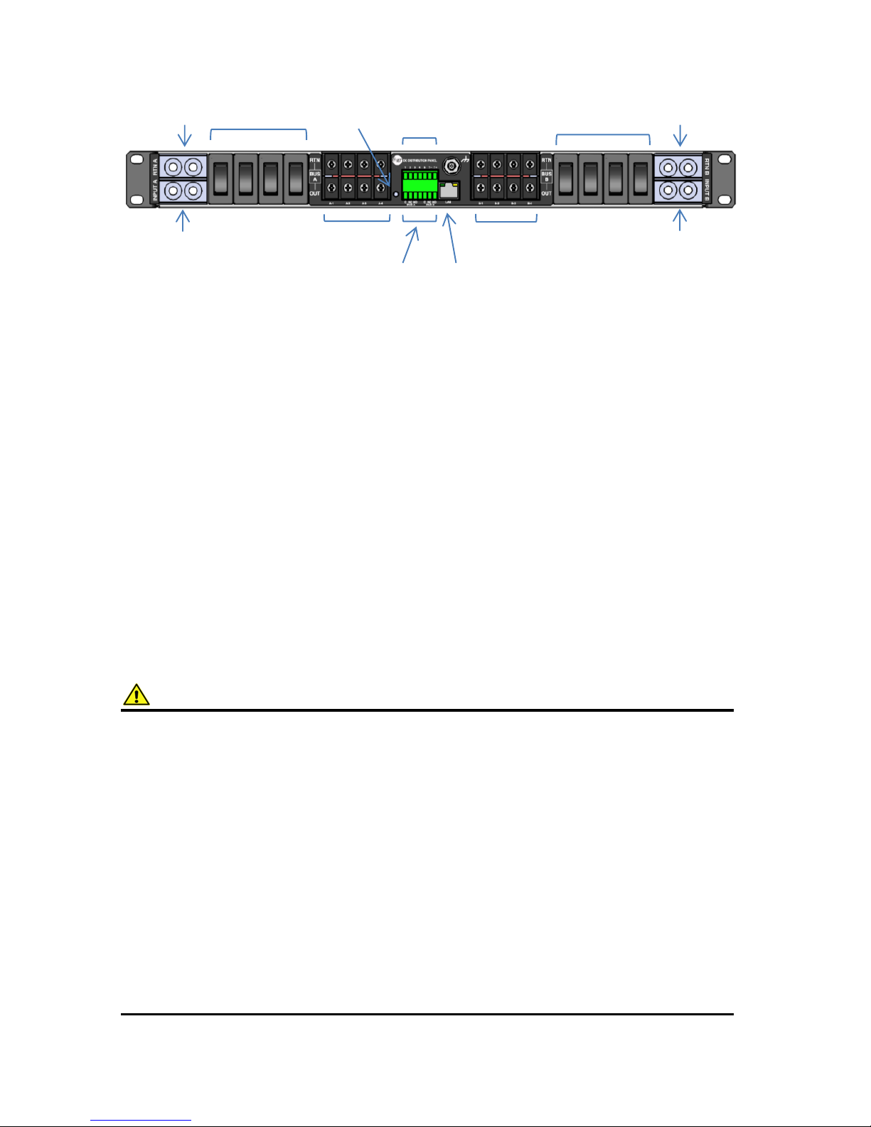
Figure 1: Front Panel Connections
Mount the Front Access Distribution Panel in a 19 inch equipment rack, using
standard rack mounting hardware. (Not provided)
Install appropriately rated circuit breakers in desired channel locations by
carefully inserting a breaker so that its mounting tabs securely snap into the
front panel (with “I/on” marking up). Install the breaker blanking plugs in any
unused locations. Breakers and plugs may be removed by using two small
screwdrivers or similar tools to press in the top and bottom mounting tabs
through the cover openings and gently prying out of the panel.
Label the output channel number of each breaker by applying one of the
supplied labels (A1 to A4, B1 to B4) below each breaker rocker.
WARNING
Risk of serious personal injury or damage to equipment and property! Always
observe the following:
Use an appropriately rated over-current protection device in line with the
main battery connections to the panel
Use an appropriately rated disconnect switch or circuit breaker in line with
the dc inputs to enable installation and service of the panel with the dc
source disconnected
Shut off or disconnect all dc power sources before connecting or
disconnecting wiring
Use wire and connectors rated for the maximum load current and size of
fuse or circuit breaker, and keep cable lengths as short as practical
Carefully observe wiring polarity when making input and output connections
Securely tighten all connections
Bus B Output
Breakers 1-4
Bus B Outputs
Channel 1-4
Bus B Return
(Common)
Bus A Return
(Common)
Site Alarm inputs
1-4, Temp Sense
Bus A, Bus B
Alarm out
C/NC/NO
LAN Port
10/100 Base-T
Bus A Output
Breakers 1-4
Bus A Outputs
Channel 1-4
Bus A Input
(100A cont)
Bus B Input
(100A cont)
Reset button
(recessed)

Innovative Circuit Technology Ltd. 7
Bond the panel chassis to the rack system ground, connecting a ground wire with
ring tongue to the front panel ground stud. (1/4-20 thread)
Connect Bus A loads to output channels A1 to A4 using suitably rated wire sized
for the breaker installed on the channel, with crimped on spade lug terminals
compatible with the output terminal block screws. Note which load is connected
to each channel, for future reference.
Repeat for the Bus B loads if required. The unit may be operated with either Bus
A or Bus B powered, or both.
NOTE!
All channel RTN lines, and the main high power Bus A and Bus B RTN terminals
are common, and tied to a single internal Return bus. Bus A and Bus B inputs can
be wired to a different dc voltage (10 to 60Vdc) of either polarity, but must share
a common RTN voltage, normally at earth potential.
Connect the main Bus A RTN line to the external battery or power supply return
using suitably sized wire and dual hole lug connector rated for up to 100A
continuous current. Connect the lug to the dual ¼-20 thread Bus A Rtn studs, and
then securely fasten with the supplied hardware.
Connect the Bus A Input through a suitably rated disconnect switch (set in the
open position) with a fuse or circuit breaker rated for 100A max continuous
operation to the external battery or power supply output, using suitably sized
wire and a dual-hole Lug connector rated for 100A continuous current. Connect
the Input lug to the dual ¼-20 thread Bus A Input studs, then securely fasten with
the supplied hardware. Snap the clear cover on to the Bus A input connector to
help prevent accidental contact with the input stud connections.
Repeat input wiring for the Bus B input, its power source and over current
protection device, if the Bus B outputs are to be used. Bus A and Bus B Input and
output Return lines are internally connected together, so will share a common
ground. The Bus A and Bus B Input terminals are isolated, and support operation
from separate + or – 10 to 60V power sources, as long as they share a common
Return potential.
Connect the two form-C relay bus alarm outputs to an external monitoring
system if needed, by stripping and terminating 16-28AWG alarm wiring in the
Alarm 7-pin connector plug (lower), and installing in the front panel. Each Bus
Alarm output will trigger for any breaker open, or other alarm related to any
channel on that bus (Factory Default). Most alarm conditions can be masked off
so that they will not trigger the Alarm output if required, using the web based
graphical interface.

8 Innovative Circuit Technology Ltd.
Bus Alarm Connector: (Lower connector plug)
Pin (L-R)
Alarm Function
1
Bus A - Alarm Output common
(0.5A 65Vdc max)
2
Bus A - Alarm Output normally
closed for alarm condition (NC)
3
Bus A - Alarm Output normally
open for alarm condition (NO)
4
No connection
5
Bus B - Alarm Output common
(0.5A 65Vdc max)
6
Bus B - Alarm Output normally
closed for alarm condition (NC)
7
Bus B - Alarm Output normally
open for alarm condition (NO)
Connect up to 4 dry contact type site sensors (such as door/window sensors,
smoke alarm, water detectors etc.) by stripping and terminating 16-28AWG
alarm wiring and connecting to the four Site Alarm Inputs on the 7 pin removable
Site Monitor Plug (upper), if desired. These inputs may be configured to activate
the panel Alarm outputs, or send an alarm e-mail on network connected units.
The external sensor contacts must be voltage free; as a small sense current is
supplied from the panel Alarm Input pins to detect the external contact open or
closed state. Refer to the Web Based Interface section for information on how to
configure and use the four Site Alarm inputs.
Connect an optional ICT external temperature sensor (ICT-TMP) to the two TMP
inputs if you need to remotely monitor the temperature of a battery pack or
enclosure.
Site Monitor Inputs: (Upper connector plug)
Pin (L-R)
Site Monitor Input Function
1
Contact Input 1
2
Contact Input 2
3
Contact Input 3
4
Contact Input 4
5
Monitor Return (common for
4 monitor inputs)
6
Remote Temperature Sense
7
Remote Temperature Sense

Innovative Circuit Technology Ltd. 9
Connect a standard 10/100 Base-T Ethernet cable to the RJ-45 LAN port on the
front panel to remotely monitor, control and reconfigure the panel settings from
a remote computer.
OPERATION
Ensure the correct circuit breakers are installed in each channel location that will
be used to power a load.
Energise each bus by closing the main external breaker or disconnect device on
the bus input lines. Switch on the front panel channel breakers for all connected
outputs, and check that the internal channel relays have closed by verifying that
the connected loads are energised. (Note that all output channels on a bus will
be disabled and network communication will be dropped if the bus voltage drops
below approximately 6V for more than 3s. Normal operation will be restored
once the bus voltage is above 8V)
Switch off any unused internal channel relays to reduce the power consumed by
the panel, using a networked computer and Web Browser. See the TCP/IP Web
Based Utility section, Output On/Off Buttons. (Each channel relay consumes
approximately 2W when closed; the factory default setting is for all outputs to be
on)
Status Indicators and Alarms
The Form-C Bus Alarm contacts are used to indicate an alarm condition.
Alarm
Trigger Condition
Channel Output
Bus Alarm
Contact
Breaker Off
Breaker opens or is
removed
Off
On
Bus Undervoltage
Bus V drops below UV
threshold
No change1
On
Bus Overvoltage
Bus V rises above the
OV threshold
No change
On
Bus Overcurrent
Bus current exceeds
the OC threshold
(default 100A)
No change
On
Output Overcurrent
Channel output current
exceeds OC threshold
Off2
On
No power to
Unit
Loss of bus input power
source
Off
On
1
All channel relays will be open if Bus Voltage is <6V, and recover for Bus Voltage >8V
2
The channel may be user configured to disable the output for an Over-current Alarm
10 Innovative Circuit Technology Ltd.
Alarm
Trigger Condition
Channel Output
Bus Alarm
Contact
Site Alarm
Input
Alarm contact on input
1 to 4
No change
On3
Remote Temp
Alarm
Adjustable over or
under temperature
threshold hit
No change
On3
The unit may also be configured to send an alarm e-mail to multiple user set email addresses for any of the alarm conditions, by enabling the e-mail function
on each alarm setup page on the web based interface. (no e-mail will be sent
when power is disconnected from the unit, due to loss of network control)
TCP/IP WEB BASED INTERFACE
These panels are equipped with a built in web server and Graphical User
Interface (GUI) to enable full remote monitoring and control using any standard
web browser, such as Microsoft Explorer, Google Chrome, or Mozilla Firefox. To
connect with your networked panel, do the following:
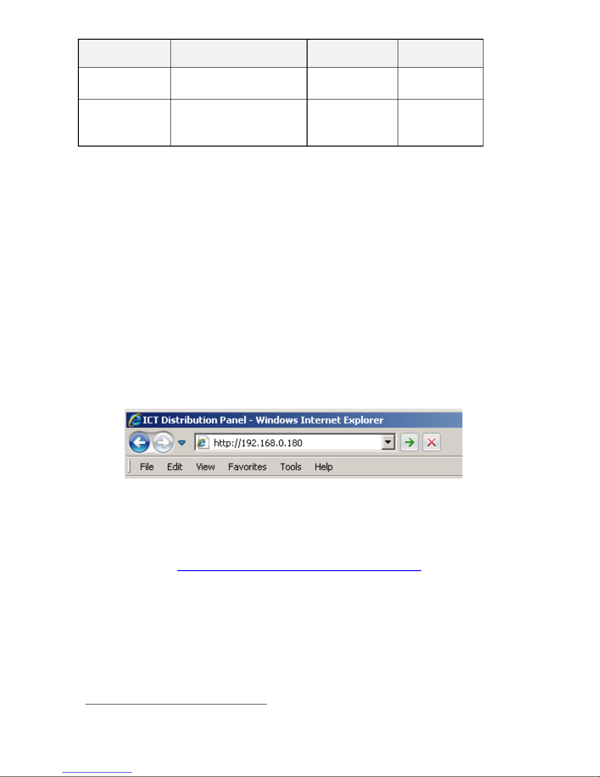
1. Start Your Browser.
2. Enter the IP address of the panel in the address field of your browser as
shown.
Typically your panel will be connected to a network with a DHCP server,
and will be assigned an IP address automatically. To find the current
address of your panel run the ICT IP Address Discovery tool, after
installing it on your Windows computer (tool available for download
from ICT http://www.ictcorporate.com/resources/tools/ ) otherwise the
panel will use the factory default IP address of 192.168.0.180, as shown
above.
3. Enter your user name and password. The default Administrator user
name is admin, with no password.
3
Use the web interface to configure each alarm input to trigger either Bus A, B or both
alarm contacts
 Loading...