

ICT ICT24024-15BC2, ICT24012-30BC2M, ICT24024-7BC2M, ICT24024-7BC2, ICT24048-7BC2M Instruction Manual
...
IntelliCharge Battery
Charger Series
INSTRUCTION MANUAL
855-342-000
Innovative Circuit
Technology Ltd.
Models:
ICT24012-30BC2, ICT24012-30BC2M
ICT24012-15BC2, ICT24012-15BC2M
ICT24024-15BC2, ICT24024-15BC2M
ICT24024-7BC2, ICT24024-7BC2M
ICT24048-7BC2, ICT24048-7BC2M

2 Innovative Circuit Technology Ltd.
WARNING
Risk of serious personal injury or damage to equipment and property! Always
observe the following:
• Install and operate unit in a Restricted Access location, such as an enclosed
equipment rack
• Operate the supply from a grounded 3-pin 120Vac or 230Vac outlet (50 or
60Hz) with a branch circuit breaker rated 20A or less
• Use only a Lead-Acid battery with rating and capacity appropriate for the
model charger in use
• Use an appropriate dc over-current protection device in line with the battery
connection
• Use a disconnect switch or circuit breaker in series with the battery
connection, to ensure installation and service is done with the battery deenergised
• Use wire and connectors rated for the maximum load current and size of
battery fuse or circuit breaker
• Ensure battery polarity is correct before connecting
• Do not attempt to charge a frozen battery
• Handle batteries with care, do not short circuit battery terminals
CAUTION
Risk of personal injury or damage to equipment! Always observe the following:
• Install in a protected environment, keep sources of moisture away from unit
• Ensure the total power consumption of the load does not exceed the rated
capacity of the charger output
• Do not block air inlet or outlet openings in the unit
• Do not place the charger directly above or below a battery, due to possible
presence of corrosive and/or flammable gasses
Rev 1.04
2018
Copyright © 2018 Innovative Circuit Technology Ltd. All rights reserved. No part of this
publication may be reproduced, stored in a retrieval system or transmitted in any form or by
any means, electronic, mechanical, photocopying, recording or otherwise, without the prior
written consent of Innovative Circuit Technology Ltd.

Innovative Circuit Technology Ltd. 3
INTRODUCTION
The ICT BC2 IntelliCharge series of intelligent battery chargers provide reliable dc
power to a system while precisely maintaining an external back-up battery using
an intelligent temperature compensated fast-charge algorithm. The wide-ranging
power factor corrected input supports operation worldwide, while a built in Low
Voltage Disconnect (LVD) relay will protect the battery from over discharge after
prolonged periods of backup operation when AC power has failed. Features
include:
• Dedicated independently controlled backup battery port with LVD relay
• Intelligent 3-stage fast charge algorithm for battery
• Optional remote battery temperature sensor for precise charge voltage
compensation (from -30C to +40C)
• Selectable battery charge settings for AGM, Flooded, or Gel batteries, or
fixed Float voltage operation
• Selectable charge rates to accommodate lower capacity batteries
• Wide range Power Factor corrected AC input supports operation world
wide
• Floating Form-C alarm contact output supports remote monitoring of
unit operation
Model1
Output
Voltage2
Max Output
Current
Continuous
Output Current
ICT24012-30BC2
13.65V
30.0A
30.0A
ICT24012-15BC2
13.65V
15.0A3
12.0A
ICT24024-15BC2
27.3V
15.0A
15.0A
ICT24024-7BC2
27.3V
7.5A3
6.0A
ICT24048-7BC2
54.6V
7.5A
7.5A
Optional Accessories:
19 inch rack mounting kit (mount up to 2 chargers): ICT-RMK5
Remote Battery Temperature Sensor (10ft): ICT-TMP
INSTALLATION
Perform a quick physical check of the unit as it is being taken out of the box to
ensure it has not been damaged during shipping. Check for the included parts
and accessories shipped with your unit:
• 3 pin Form-C alarm connector plug (installed on unit)
1
A suffix letter “M” at the end of the model number is added to denote versions with
optional front graphic meter display
2
Fixed AGM Float Voltage
3
Max output current less than 10% duty cycle
4 Innovative Circuit Technology Ltd.
• Power cord (North America 120V 15A)
• Output connector cover (installed on connector)
• Instruction Manual
WARNING
Risk of serious personal injury or damage to equipment and property! Always
observe the following!
• Ensure the nominal battery voltage is correct for the model of charger, and
that the battery positive is connected to the BAT positive (+) terminal and
the battery negative is connected to the BAT negative (-) terminal.
• Use an appropriate dc over-current protection device such as a fuse or
circuit breaker in line with the battery connection
• Do not tie any of the LOAD and BATT terminals together, as this will bypass
internal circuitry
• Make Ground connection to only a single LOAD or BATT terminal if required.
Do not ground both LOAD and BATT as this will bypass internal circuitry
• The internal LVD relay switches the BATT + terminal. Do not connect the
battery + to any other terminal
• AC input wiring to the charger must be protected using an outlet with a
branch rated circuit breaker of 20A or lower value
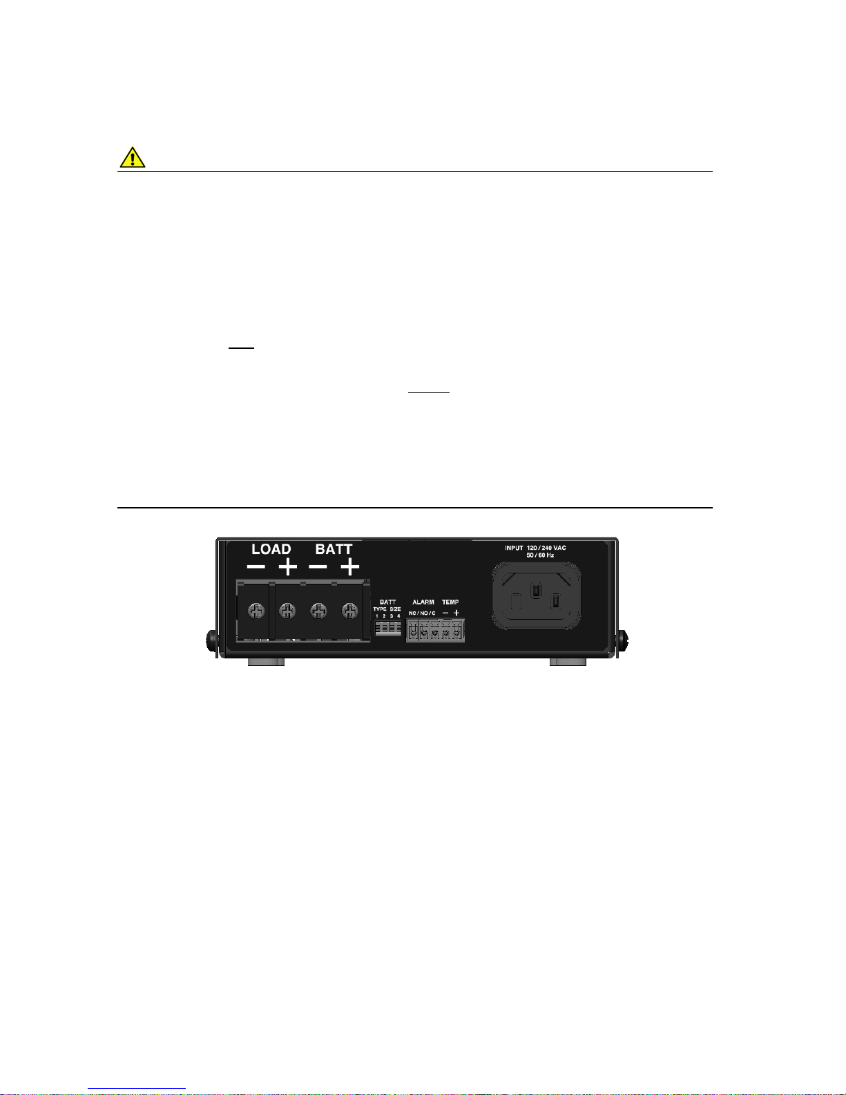
Rear View (Connectors and BAT Switch 1-4)
Mounting:
The unit should be placed on a shelf near the backup battery and the load in a
location that restricts access to the wiring and battery terminals, such as in an
enclosed equipment cabinet. The unit may also be rack mounted using the
optional 19” 1U rack mounting kit (capacity for 2 chargers) ICT-RMK5.
Configure the Charger:
Always switch off the charger before changing the settings or making connections
to the unit.
• Choose a lead-acid battery bank with a nominal voltage rating
(12/24/48V) that matches the BC2 Series charger output.
• Configure the unit for the battery Type (BATT switches 1, 2) and
maximum charge current Size (BATT switches 3, 4) for the backup
battery used, by setting the BATT switches 1-4 on the back panel per the
 Loading...