

ICT ICT24012-20CM, ICT24012-12CM, ICT24024-10CM Instruction Manual

PROTECTION FEATURES
Internal circuitry will help protect the load, battery and power
supply in case of the following events:
• Internal temperature too high - will reduce output current
until stable temperature maintained
• Input ac voltage out of range - will shut off output,
automatically restarts when in operating range
• Output Short Circuit – current regulated to less than the
max rated level
• Output Over Voltage – will shut off output, automatically
restarts after delay
• Battery current too high – dc output fuse will open
• Reverse Battery connection – dc output fuse will open
• Input Over current – internal AC fuse will open
SPECIFICATIONS
Input Voltage: 100 – 264Vac 50/60Hz
Input Power Factor: 0.99 (120Vac input)
V-output Line Regulation: +/- 0.1%
V-output Load Regulation: +/- 0.2%
Electronic current limit: Constant current regulation with
fold back for short circuit
conditions
Operating Temperature: -30°C to 60°C1
Output Grounding: Positive, Negative or floating
Efficiency: 88% typical (120Vac)
EMC: Meets FCC part 15 class B limits
Safety: Designed to meet EN60950-1
1
Reduce output current 1% per °C for ambient above 50°C
LIMITED WARRANTY
ICT Limited Warranty is only intended for the benefit of the original
Purchaser of this product. This Warranty is not transferable or
assignable without the prior written permission of ICT. ICT’s sole
obligation and liability under this warranty is limited to either
repairing or replacing defective products at the sole discretion of
ICT. When repairing or replacing the products, ICT may use
products or parts that are new, equivalent to new or reconditioned. Parts repaired or replaced during the warranty period
will be under warranty for the remainder of the warranty period.
The warranty period on ICT products purchased new from ICT is
two years. The warranty period for a repaired product or part
thereof is ninety (90) days or the remainder of the unexpired term
of the new product warranty period, whichever is greater. Repair
or replacement of a defective product or part does not extend the
original warranty coverage period.
No claim will be accepted unless written notice of the claim is
received by ICT in accordance with ICT’s Return Material
Authorization (RMA) procedure, as soon as reasonably possible
after the defect is discovered. A valid product serial number must
be provided with the RMA claim to prove eligibility. The RMA form
is available on the ICT website at www.ictpower.com/support/warranty-repair/.
The Purchaser shall at their own risk and cost return the defective
product to ICT’s factory or designated repair center once an RMA
is issued by ICT. Return of the products to the customer after
repair is completed shall be prepaid by ICT unless otherwise
mutually agreed between the parties. Products shipped to ICT
which have incurred freight damage will not be covered by this
Warranty and any repairs or replacement parts, components or
products needed will be invoiced in the full current price amount
and returned freight collect to Purchaser. It is the Purchaser’s
responsibility to check the product upon receipt for any damage
during shipping and to contact the carrier or shipper regarding
such damage. Product that is returned as defective, which is
determined to operate within published specifications will be
returned to the Purchaser freight collect.
This Warranty will be void if the product has been subjected to
misuse, neglect, accident, exposure to environmental conditions
not conforming to the products’ limits of operation, improper
installation or maintenance, improper use of an electrical source,
defects caused by sharp items or by impact pressure, a force
majeure event, has been modified or repaired by anyone other
than ICT or its authorized representative, has been subjected to
unreasonable physical, thermal or electrical stress, improper
maintenance, or causes external to the unit including but not
limited to general environmental conditions such as rust, corrosive
atmospheres, sustained temperatures outside the specified
operating range of the equipment, exposure to power surges
and/or electrical surges, improper grounding, mould or dust,
animal or insect damage, water damage or immersion in liquid of
any kind.
ICT does not control the installation and use of any ICT product.
Accordingly, it is understood this does not constitute a warranty of
performance or a warranty of fitness for a particular purpose.
Model:
12V 20A
12V 12A
24V 10A
Output Voltage
(Nominal, +/-
0.5%)
13.8V
13.8V
27.6V
Continuous
Current Rating
(at nominal
output voltage)
20A
10A
10A
Output Current
Limit (+5%,-0%)
20A
12A
10A
Output V Noise
(max)
25 mVrms
25 mVrms
25 mVrms
Input Current
max at 100Vin
3Aac
1.8Aac
3Aac
Output Power
(max rated)
276W
166W
276W
Models:
ICT24012-20CM
ICT24012-12CM
ICT24024-10CM
Innovative Circuit
Technology Ltd.
CM Series DC Power
Supply
INSTRUCTION MANUAL
855-159-001
INNOVATIVE CIRCUIT TECHNOLOGY LTD.
26921 Gloucester Way
Langley, British Columbia, Canada V4W 3Y3
T 604.856.6303 F 604.856.6365 www.ict-power.com
ICT CM SERIES POWER SUPPLY
The CM Series off-line power supplies from ICT provide a
reliable 275 Watts of dc power with a built-in battery back-up
port and low current float charger for powering 12, or 24Vdc
based systems. With an efficient wide range power factor
corrected input the units are useable world-wide, and their built
in flange mounting points and terminal block connections make
installation simple. Temperature controlled fan cooling2 ensures
long life operation over a wide range of ambient temperatures.
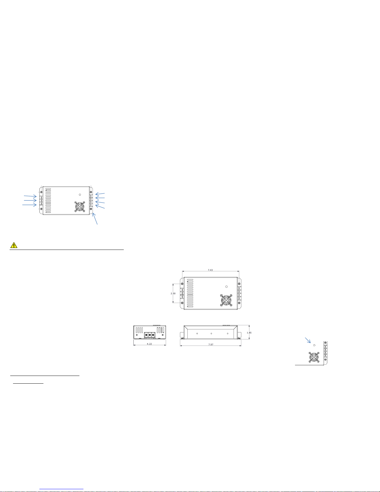
CONNECTION DIAGRAM
WARNINGS
Risk of personal injury or damage to equipment and
property! Always observe the following:
• Install and operate unit in a Restricted Access location,
such as an enclosed equipment rack
• Operate the supply from a grounded 3-pin 120Vac or
230Vac outlet (50 or 60Hz) with a branch circuit breaker
rated 20A or less
• Use an appropriate dc over-current protection device in
line with the optional battery connection
• Use wire and connectors rated for the maximum load
current and size of battery fuse or circuit breaker
• Ensure battery polarity is correct before connecting
• Ensure required load current does not exceed max rating
of unit
INSTALLATION
Mount the unit on a horizontal flat surface in a restricted access
environment such as an equipment rack or cabinet, (ensuring
air vents are not blocked) using four 6-32 mounting screws (not
supplied). Make the following connections using wire and
2
On 276W models
connectors appropriately rated for the maximum input and
output current rating of the unit:
• Connect the supply POS output terminal to the load
positive input
• Connect the supply RTN output terminal to the load
negative input terminal
• Connect an optional external battery if dc back-up
capability is desired
o Choose a lead-acid battery with a float voltage rating
that matches the Panel Mount Series output voltage,
and has a 10 Amp-hour (Ahr) capacity rating or
greater. Larger capacity batteries will provide a longer
back up time in the event of an AC power failure
o Connect the battery negative to the supply RTN
battery terminal
o Connect the battery positive to an over current
protection device (fuse or breaker)
o With the battery fuse removed or breaker open
connect the fuse or switch to the supply BAT(+)
terminal
o Either the POS or NEG lead may be connected to
earth ground if required by the application, as the
supply output is isolated from the chassis and ground.
• Connect a de-energized AC power cord to the AC input
terminals of the supply, then plug into a grounded 3
terminal 120Vac or 230Vac 50/60Hz outlet.
DIMENSIONS (inches)
OPERATION
Once the unit is mounted and all wiring is connected per the
INSTALLATION section instructions, connect a dc voltmeter to
the output load terminals and apply AC power to the input.
Check that the DC output voltage is within the normal range for
the model in use.
The unit will now power the load and trickle charge the optional
back up battery at the rated output voltage setting of the unit.
The output will continue to be powered directly from the
battery if the AC input is off for any reason; ensuring critical
loads are powered continuously.
USING the OPTIONAL BACKUP BATTERY
The CM Series uses an isolation diode between the BAT
terminal, and the Load + output. When in back-up mode the
voltage supplied to the load will be the external battery voltage
less the drop across the diode, which is approximately 0.6V. So
for example a battery at a voltage of 12.7V will provide
approximately 12.1V to the load.
For prolonged AC outages, the battery may be discharged to a
very low level, as there is no internal low-voltage-disconnect
device. It is good practice to ensure the battery has enough
capacity to power the load for long durations and still ensure it
is not discharged below approximately 11V. This will help to
prevent permanent loss of battery capacity due to overdischarge.
Excessive load current from the battery is limited by an internal
ATO type fuse. A short circuit or other over-current event on
the load wiring will cause this fuse to open, protecting the
internal circuitry. This fuse may be replaced by disconnecting
the unit from all power sources, removing the cover, and
replacing fuse F3 with a fuse of the same type and rating.
The output voltage may be adjusted slightly to better match the
float voltage ratings of specific batteries, by setting the trim-pot
as shown with an insulated adjusting tool.
Disconnect any loads or battery, and connect an accurate
voltmeter to the output terminals. With the unit powered
observe the output voltage and slowly adjust the output setting
to the desired level.
Switch off the AC power and reconnect all output wiring.
AC Input
(100-264Vac)
Ground
Neutral
Line
DC Output
+ Load
RTN
RTN
+ Battery
6-32 Threaded mounting
inserts (4)
Output Voltage Adjustment Trim Pot
 Loading...