

ICT ICT206012-70AI2, ICT206024-35AI2, ICT206024-50AI2, ICT206012-100AI2 Instruction Manual
THEPOWEROFRELIABILITY
INNOVATIVE CIRCUIT TECHNOLOGY LTD.
855-334-001
ICT
INSTRUCTION MANUAL
DC SITE CONVERTERS
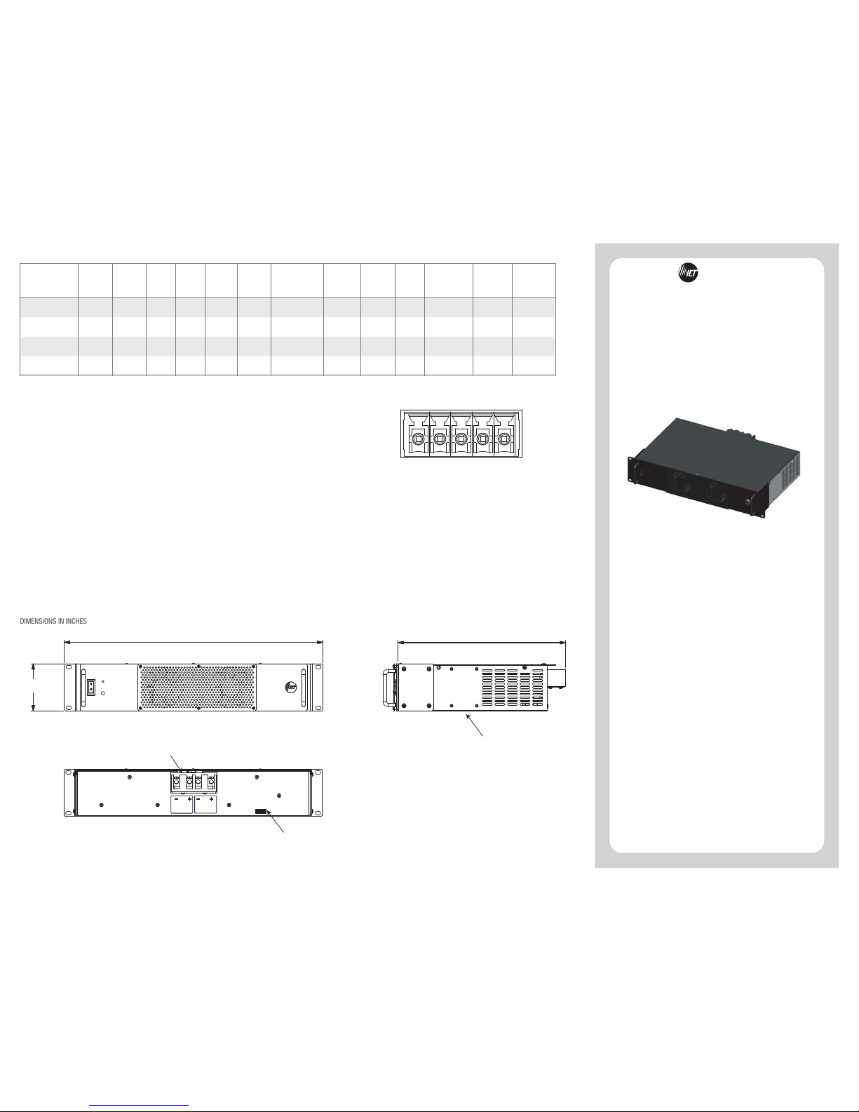
DIMENSIONS IN INCHES
OUTLINE DRAWING
19.00
3.47
12.33
OUTPUT
INPUT
REMOTE / STATUS CONNECTOR
REMOTE / STATUS CONNECTOR
DC CONNECTOR
WIRE SIZES: #2 - #14 CU/ #8 AL
ALTERNATE RACK EAR POSITION
Input
Voltage
Range
Output
Voltage
Output
Current
(Cont.)
Output
Current
(Peak)
Current
Limiting
Line
Regulation
Load
Regulation
Output
Ripple
(Max)
Efficiency
(Typ @ 48V In)
ICT206012-70AI2
ICT206012-100AI2
20-60 VDC
13.8 VDC
+/- 300 mV
64.0 Amps 70.0 Amps
74.0 Amps
+/- 5%
20mV RMS 90%
Input
Current
@ Vin(min)
55 Amps
78 Amps
13.8 VDC
+/- 300 mV
96.0 Amps 105.0 Amps
110.0 Amps
+/- 5%
20mV RMS 90%
20-60 VDC
Model
Number
0.5% 3.0%
0.5% 3.0%
Operating
Temperature
Range
-20°C to +40°C
-20°C to +40°C
SPECIFICATIONS
PIN 1: COMMON
PIN 2: NC
PIN 3: NO
PIN 4: SD +
PIN 5: SD -
1 2 3 4 5
REMOTE STATUS (COMMON, NC, NO)
The Common, NC, and NO contacts of a small Form C relay are
provided for alarm monitoring. A voltage comparator monitors the
output voltage of the system and drives the relay. When the output
voltage is good the NO pin is connected to the COMMON pin. The
relay is rated 1A / 30VDC.
REMOTE SHUTDOWN (SD+, SD-)
When 5-15Vdc is applied between these two pins, the
output of the unit is disabled. Please observe polarity.
Output
Adjust
(Typ)
12.5 -
14.5 VDC
12.5 -
14.5 VDC
Under / Over
Voltage Shutdown
< 20 VDC /
> 60 VDC
< 20 VDC /
> 60 VDC
ICT206024-35AI2
20-60 VDC
27.6 VDC
+/- 300 mV
25.0 -
29.0 VDC
32.0 Amps 35.0 Amps
37.0 Amps
+/- 5%
< 20 VDC /
> 60 VDC
0.5%
3.0%
20mV RMS
90% 55 Amps
-20°C to +40°C
ICT206024-50AI2
20-60 VDC
27.6 VDC
+/- 300 mV
25.0 -
29.0 VDC
< 20 VDC /
> 60 VDC
0.5%
3.0%
20mV RMS
90% 78 Amps
-20°C to +40°C
48.0 Amps 50.0 Amps
52.0 Amps
+/- 5%

ICT Ltd. warrants to the original consumer purchaser that this
product shall be in good working order, free from defects in
materials and workmanship, for a period of three (3) years from the
date of purchase. Should failure occur during the above stated time
period, then ICT will, at its option, repair or replace this product at
no additional charge except as set forth below. All parts, whether
for repair or replacement, will be furnished on an exchange basis.
All exchange pieces become the property of ICT. This limited
warranty shall not apply if the ICT product has been damaged by
unreasonable use, accident, negligence, disaster, service, or
modification by anyone other than the ICT factory.
Limited warranty service is obtained by delivering the product
during the above stated three (3) years warranty period to an
authorized ICT dealer or ICT factory and providing proof of purchase
date. If this product is delivered by mail, you will insure the product
or assume risk of loss or damage in transit, and prepay shipping
charges to the factory.
Every reasonable effort has been made to ensure that ICT product
manuals and promotional materials accurately describe ICT product
specifications and capabilities at the time of publication. However,
because of ongoing improvements and updating of ICT products,
ICT cannot guarantee the accuracy of printed materials after the
date of publication and disclaims liability for changes, errors or
omissions.
If this ICT product is not in good working order, as outlined in the
above warranty, your sole remedy shall be repair or replacement as
provided above. In no event will ICT be liable for any damages
resulting from the use of or the inability to use the ICT product,
even if an ICT employee or an authorized ICT dealer has been
advised of the possibility of such damages, or for any claim by any
other party.
ICT reserves the right to make changes without further notice to
any products or documentation for improvement of reliability,
function, or design.
ICT Ltd. does not recommend use of its products in life support
applications wherein a failure or malfunction of the product may
directly or indirectly threaten life or cause injury. The user of ICT
products, which are to be used in life support applications as
described above, assumes all risks of such use and indemnifies ICT
against all damages.
LIMITED WARRANTY
INNOVATIVE CIRCUIT TECHNOLOGY LTD.
26921 GLOUCESTER WAY LANGLEY, BRITISH COLUMBIA, CANADA V4W 3Y3
T 604.856.6303 F 604.856.6365 www.ict-power.com
THEPOWEROFRELIABILITY
NOTES
Isolated converters can be used in parallel or series
configuration. Please contact ICT for further information.
These converters incorporate a special noise filter design.
For proper filter operation, the converter must be chassis
grounded.
Check for proper voltage at input while converter is under
load. This unit has undervoltage and overvoltage
shutdown, so temporary voltage fluctuations outside of the
rated input voltage range of the unit will cause loss of
output. The converter will automatically restart when the
input voltage is within range.
Verify the load current. This converter has current limiting
so currents exceeding the rated current limit will cause loss
of output. The converter will automatically restart when
the excess load is removed.
Check the environment. This converter features thermal
shutdown so if the environment is too hot or cooling vents
are blocked the converter will turn off. The unit will restart
when the ambient temperature is within normal operating
limits.
TROUBLESHOOTING
Incorrect wiring may result in personal injury or serious
damage to both the converter and equipment
connected to the converter.
Do not place unit on or near sources of heat and
moisture.
Servicing of unit should be done only at ICT factory.
WARNING
ICT DC SITE CONVERTERS
SETUP
ICT DC SITE CONVERTERS feature an all-new design that
builds on the ICT legacy of reliability and performance.
ICT DC SITE CONVERTERS are fully isolated. They can
operate from a negative or positive ground electrical system,
and are ideal for applications where complete isolation is
required between primary and secondary circuits, as well as
from the chassis.
These instructions should be read before using the product
and saved for future reference.
Mount converter securely
Do not apply power until unit is completely wired
Connect load to output
Connect power source to input using appropriate fusing
for the application using wire of size and type
appropriate for the current and length of the connection
The front panel switch turns the unit on and off. This is
a low current switch that inhibits the internal modules
but does not interrupt the input power.
A front panel potentiometer allows adjustment of the
output voltage. Always verify the output voltage of the
system with a meter while adjusting by connecting
voltmeter probes to the output terminals of the system.
The front panel LED is lit when the output voltage is
within typical operating range.
A remote access terminal is available on the rear of the
unit that allows remote shutdown of the unit as well as
monitoring of output voltage status. See the
“REMOTE/STATUS CONNECTOR” section for further
details.
 Loading...