


I.C.P. Srl Savannah™VG FLIGHT MANUAL
AIRPLANE FLIGHT MANUAL
Pag. 1
Savannah™VG
Copyright I.C.P. 2002
Savannah™ is registered trademark solely owned by ICP Srl and their use in any form is strictly
forbidden.
The content of this manual is the sole property of I.C.P. srl and cannot be reproduced by third
parties in any form whatsoever without ICP’s previous written authorization.
Issue 1/Revision 03
Jan.2012 Tel. 011.9927503 Fax 011.9927266
ICP Srl – S.P.16 km 15,150 14022 Castelnuovo Don Bosco (AT)
I.C.P. Srl Savannah™VG FLIGHT MANUAL
LOG OF REVISIONS
Pag. 2
Revision
Number
00
01
02
03
Revised
Description of Revision Date
Pages
All New emission 07/06
36, 37 Updated data on W&B 01/07
19, 37 Updated front limit CG and minimum WTO 03/07
all General revision 01/2012
Issue 1/Revision 03
Jan.2012 Tel. 011.9927503 Fax 011.9927266
ICP Srl – S.P.16 km 15,150 14022 Castelnuovo Don Bosco (AT)

I.C.P. Srl Savannah™VG FLIGHT MANUAL
TABLE OF CONTENTS
SECTION 1 TECHNICAL DESCRIPTION
SECTION 2 LIMITATIONS
SECTION 3 EMERGENCY PROCEDURES
SECTION 4 NORMAL PROCEDURES
SECTION 5 PERFORMANCE
SECTION 6 WEIGHT AND BALANCE
Pag. 3
Issue 1/Revision 03
Jan.2012 Tel. 011.9927503 Fax 011.9927266
ICP Srl – S.P.16 km 15,150 14022 Castelnuovo Don Bosco (AT)

I.C.P. Srl Savannah™VG FLIGHT MANUAL
TABLE OF CONTENTS
SECTION 1
TECHNICAL DESCRIPTION
Paragraph Page
Airplane views and dimensions 5
1.1 General specifications 7
1.2 Structure 8
1.3 Landing gear 8
1.4 Engine 8
1.5 Engine controls 8
1.6 Propeller 9
1.7 Fuel system 9
1.8 Electrical system 9
1.9 Cabin 10
1.10 Cabin features and upholstery 10
1.11 Ventilation 10
1.12 Cabin heating 10
1.13 Instrument panel 14
1.14 Flight controls 15
1.15 Flaps control system 15
1.16 Pitot-static system 15
1.17 Baggage compartment 15
Pag. 4
Issue 1/Revision 03
Jan.2012 Tel. 011.9927503 Fax 011.9927266
ICP Srl – S.P.16 km 15,150 14022 Castelnuovo Don Bosco (AT)
I.C.P. Srl Savannah™VG FLIGHT MANUAL
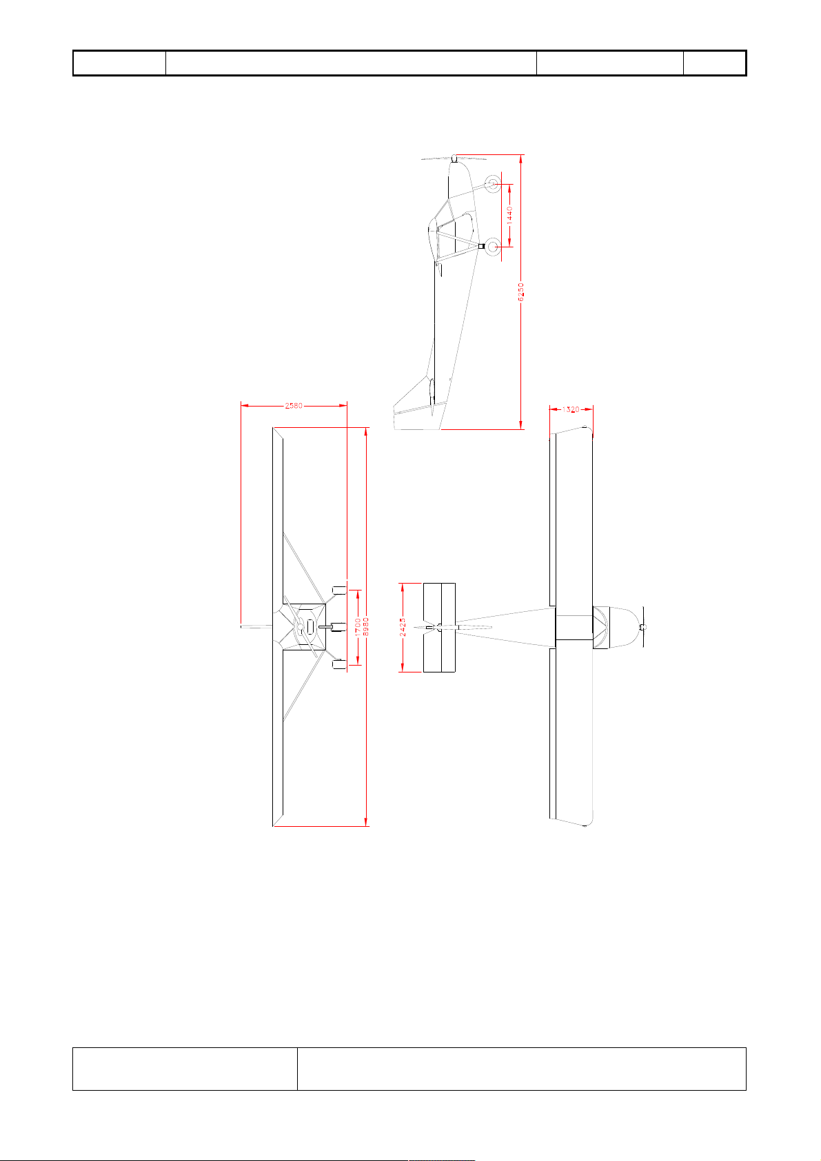
AIRPLANE VIEWS (Rotax 912/912 S)
Pag. 5
Wing span: 30ft/8.98 m
Lenght: 21.3ft/6.25m
Height: 8ft/2.58m
Track: 5.57ft/1.7m
Issue 1/Revision 03
Jan.2012 Tel. 011.9927503 Fax 011.9927266
ICP Srl – S.P.16 km 15,150 14022 Castelnuovo Don Bosco (AT)
I.C.P. Srl Savannah™VG FLIGHT MANUAL
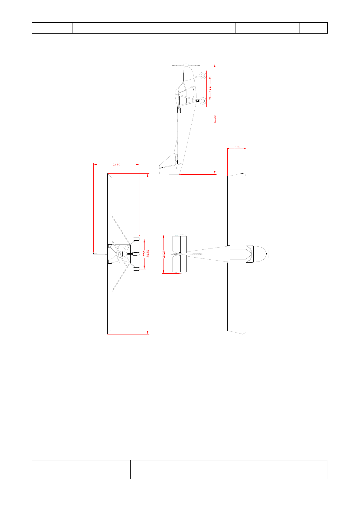
AIRPLANE VIEWS (Jabiru 2200)
Pag. 6
Wing span: 30ft/8.98 m
Lenght: 21.3ft/6.25m
Height: 8ft/2.58m
Track: 5.57ft/1.7m
Issue 1/Revision 03
Jan.2012 Tel. 011.9927503 Fax 011.9927266
ICP Srl – S.P.16 km 15,150 14022 Castelnuovo Don Bosco (AT)
I.C.P. Srl Savannah™VG FLIGHT MANUAL
Pag. 7
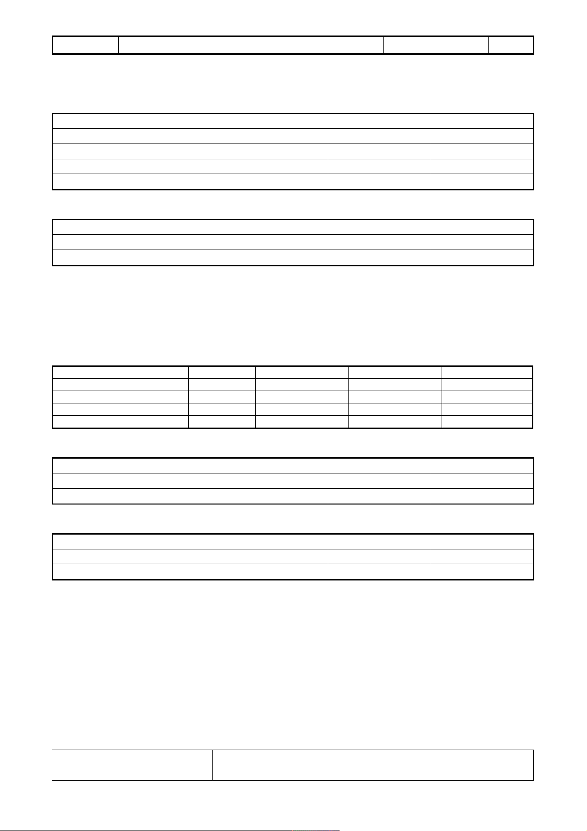
1.1 GENERAL SPECIFICATIONS
Dimensions
Wing span 30.0/8.98 ft/m
Wing area 128/11.9 sq. ft/m
2
Length 21.3/6.25 ft/m
Height 8.0/2.58 ft/m
Propeller diameter 68/1.73 in/m
Weights
Maximum take-off weight * 1000/454 lbs/kg
Empty weight** 600/272 lbs/kg
Useful load 400/182 lbs/kg
*Note: If the increase maximum take-off weight kit is installed, the Max take-off weight is increased
to 1234 lbs or 560Kg. Please make correction in your manual.
**NOTE: empty weight varies depending on the aiplane configuration requested by the owner.
Please refer to the weight and balance document to establish your precise aircraft empty weight.
Powerplant
Engine DIMENSION ROTAX 912 UL ROTAX912 ULS JABIRU2200
Take off performance 59.6 kW (5800 rpm) 75.3 kW (5800 rpm) (63.4 kW) 3300rpm
Displacement cu.in/cm
Compression ratio 9.0:1 10.5:1 8:1
Fuel consumption (75% power) gph/lt/h 4.3/16.2 4.9/18.5 3.5/13
3
73.9/1211 82.5/1352 134/2200
Fuel and oil
Fuel capacity 19/72 usgal/lt
Fuel grade Mogas/Avgas 91/100 LL
Oil capacity 3/3.16 lt/US qts
Landing gear
Wheel track 5.6/1.7 ft/m
Tire size 6 in
Tire pressure 14.5/1 psi/bar
1.2 STRUCTURE
The aircraft is a high wing single engine, with two side-by-side seats. The wings are supported by
struts and are a “high lift” NACA 650-18 modified airfoil with Junkers type flaperon (aileron + flap).
The airframe structure is full-metal with load-resisting panels. The horizontal stabilizer is a
simmetric bi-convex airfoil.
Issue 1/Revision 03
ICP Srl – S.P.16 km 15,150 14022 Castelnuovo Don Bosco (AT)
Jan.2012 Tel. 011.9927503 Fax 011.9927266

I.C.P. Srl Savannah™VG FLIGHT MANUAL
1.3 LANDING GEAR
The aircraft has a tri-cycle type landing gear. The main landing gear is made by a single-piece
aluminium alloy single-leaf leg. The nose landing gear has a telescopic, elastic chord shock absorber
and is steerable in order to ease the taxiing.
1.4 ENGINE
This aircrft has two engine installation options: the ROTAX 912 ULS/ROTAX 912 UL or
Jabiru2200. Please refer to Engine manual for any data and specifications.
WARNING: Rotax and Jabiru manufacturers issue several service and information bulletins.
It is the owner’s responsibility to acquire these documents available at www.rotax-aircraft-
engines.com or www.jabiru.net.au.
WARNING: All engines are subject to sudden stoppage. Engine stoppage can result in crash
landings, forced landings or no power landings. Such crash landings can lead to serious bodily
injury or death. Never fly the aircrafts at locations, airspeeds, altitudes, or other circumstances
from which a successful no power landing cannot be made.
These engines are not certificated aircraft engines. They have not received any safety or
durability testing and may not conform to aircraft standards.
User assumes all risks of use and fully acknowledges by his use that he knows this engine is
subject to sudden stoppage.
Pag. 8
Note: check your country’s regulations to establish the approved condition in which the
airplane can be flown (VFR/IFR, Night/Day) and the type of airworthiness certificate that can
be issued.
1.5 ENGINE CONTROLS
There are two push-pull throttle controls with a friction adjusting knob. In the Jabiru
installation the mixture control is located near the pilot’s side throttle control. In the Rotax
installation the choke is in that position. The air-box control (Rotax 912 ULS) is located near the
throttle control: pull for hot air to carburetors, push for cold air to carburetors (for values of
temperature to maintain see chapter 2.3).
The key-operated master switch connects the electrical system to the 12V battery. The whole
electrical system is protected by thermal type re-settable breakers.
The engine can be operating with the master switch OFF and the breakers OFF since the
ignition system is independent. It can only be turned off by switching OFF the two magnetos
switches. All of the electrical instruments and devices, including the engine starter will not operate
when the master switch is OFF.
WARNING: The engine may start with the master switch OFF, if the magnetos switch (even
only one) is ON and the propeller is hand rotating or windmilling. For safety, it is strongly
recommended to pull-out the master switch key when exiting the cabin.
Issue 1/Revision 03
Jan.2012 Tel. 011.9927503 Fax 011.9927266
ICP Srl – S.P.16 km 15,150 14022 Castelnuovo Don Bosco (AT)

I.C.P. Srl Savannah™VG FLIGHT MANUAL
The master switch key is located near the pilot’s throttle. All the switches and the engine
controls are turned ON if moved UPWARD or FORWARD. Only the mixture control is operated
by pulling it BACKWARD or the choke in the Rotax installation.
Pag. 9
Issue 1/Revision 03
Jan.2012 Tel. 011.9927503 Fax 011.9927266
ICP Srl – S.P.16 km 15,150 14022 Castelnuovo Don Bosco (AT)

I.C.P. Srl Savannah™VG FLIGHT MANUAL
1.6 PROPELLER
One of the following propellers may be installed on this airplane:
- “DUC Helice”, 3 blades in carbon fiber (Rotax 912 ULS), adjustable on ground.
- “DUC Helice”, 2 blades in carbon fiber (Rotax 912 UL), adjustable on ground.
- 2 BLADES IN CARBON FIBER (Jabiru2200)
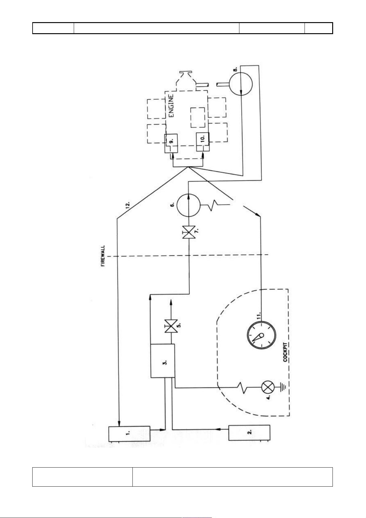
1.7 FUEL SYSTEM
With reference to fig. 1 on page 11, the fuel system is equipped with two tanks (1, 2). They
are installed in the wings and have a 72 lt (19 gal) capacity. The filler caps have a vent hole. The
reservoirs have an overcapacity fuel pipe ending below the wings. The left fuel tank has a visual fuel
level indicator located on left wing first rib. The drain valve (5) is located in the fuel tank behind the
right seat (3). A fuel reserve warning light is installed to indicate low remaining fuel in the collector
tank behind the seat. The installed fuel valve (7) is held in the OPEN position by a safety wire. That
safety wire can be broken in an emergency. This safety wire is used to prevent an accidental in-flight
fuel valve closure leading to an engine shut-down or, even worse, to a closed fuel valve take-off. The
fuel pump (8) is mechanically operated by the engine, a fuel pressure gauge is installed to check the
system operation.
Pag. 10
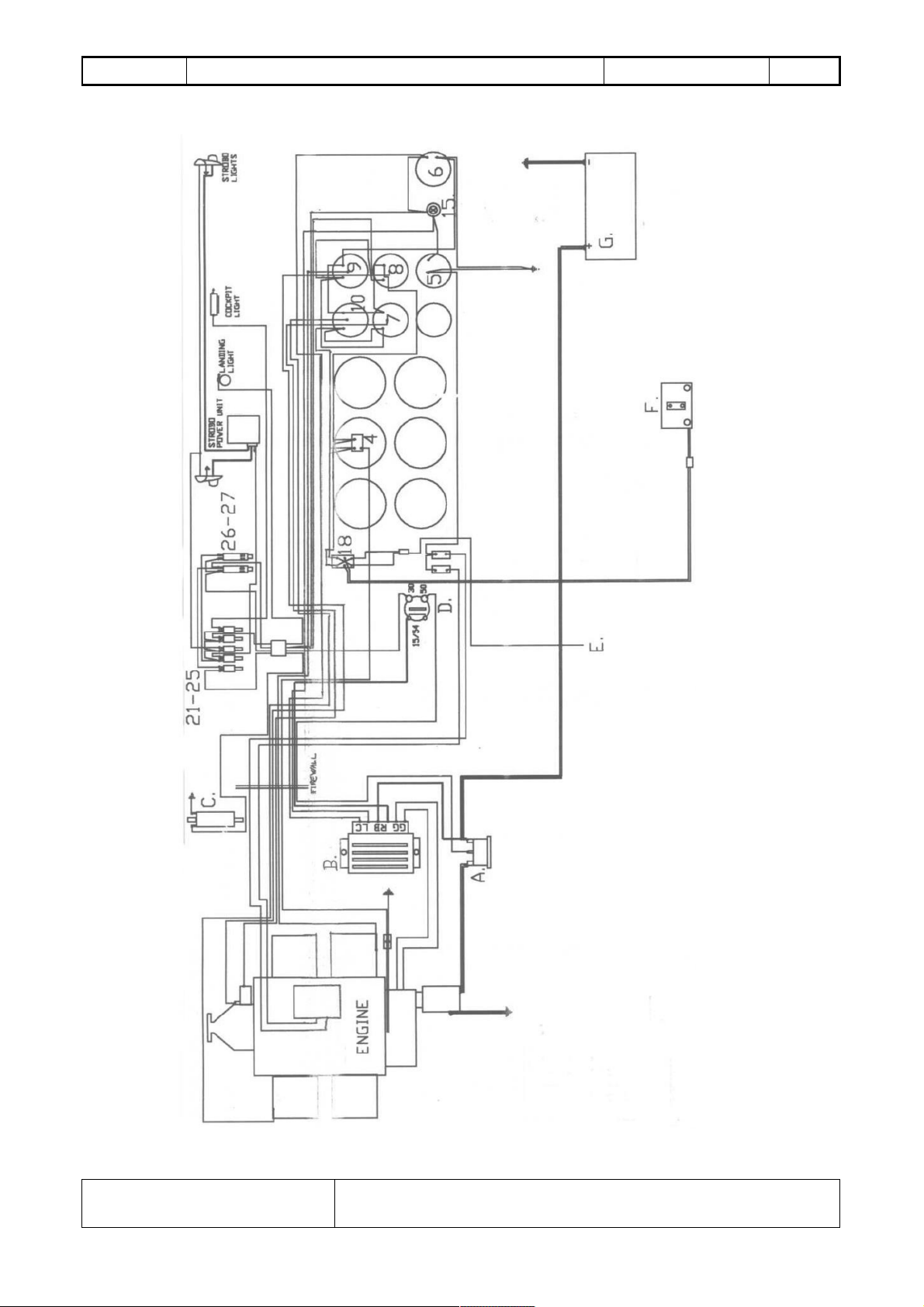
1.8 ELECTRICAL SYSTEM
With reference to fig.2 on page 12, the airplane’s electrical system includes a 12V battery, a
generator, wiring and switches to supply and connect the engine starter, an auxiliary fuel pump, anticollision, navigation lights and the avionics. A voltmeter is provided as a standard equipment.
The key-operated master switch connects the electrical system to the 12V battery. The whole
electrical system is protected by thermal type re-settable breakers.
With the master switch OFF any electrical instrument and all other electrical devices, electric
engine starter included, will not operate.
With reference to fig. 2:
A. starter relay
B. voltage regulator
C. electric fuel pump
D. master switch
E. power supply (aux)
F. elevator trim motor
G. battery
4. RPM gauge
5. hourmeter
6. voltmeter
7. left head temperature
8. right head temperature
9. oil temperature
10. oil pressure
15. low voltage warning lamp
18. elevator trim switch
21-25 switches
Issue 1/Revision 03
Jan.2012 Tel. 011.9927503 Fax 011.9927266
ICP Srl – S.P.16 km 15,150 14022 Castelnuovo Don Bosco (AT)
I.C.P. Srl Savannah™VG FLIGHT MANUAL
26-27 breakers
FUEL SYSTEM
Pag. 11
Figure nr.1
Issue 1/Revision 03
Jan.2012 Tel. 011.9927503 Fax 011.9927266
ICP Srl – S.P.16 km 15,150 14022 Castelnuovo Don Bosco (AT)
I.C.P. Srl Savannah™VG FLIGHT MANUAL
ELECTRIC SYSTEM (engines ROTAX 912 and 912S)
Pag. 12
Figure nr.2
Issue 1/Revision 03
Jan.2012 Tel. 011.9927503 Fax 011.9927266
ICP Srl – S.P.16 km 15,150 14022 Castelnuovo Don Bosco (AT)
 Loading...