

Page 1

ROCKY – 3703EVR
TM
Celeron
& Pentium® III with
Dual LAN & ATA100 IDE RAID
Integrated S3 savage4 AGP4X VGA SBC
@Copyright 2001
All Rights Reserved.
Manual first edition MAR 30,2002
The information in this document is subject to change without prior notice in
order to improve reliability, design and function and does not represent a
commitment on the part of the manufacturer.
In no even t will th e manu factu rer be liable for direct, indirect, special, incidental,
or consequen tial dam ages arising ou t of th e use or inability to use the product or
documentation, even if advised of th e possibility of such damages.
Th is document contains proprietary information protected by copyright. All righ ts
are reserved. No part of this manual may be reproduced by any mechanical,
electronic, or other means in any form without prior written permission of the
manufacturer.
Trademarks
ROCKY-3703EVR is registered trademarks of ICP Electronics Inc.; IBM PC is
a registered trademark of Intern ation al Business Machines Corporation. Intel is a
registered trademark of Intel Corporation. AMI is registered trademarks of
American Megatrends Inc.. Other product names mentioned herein are used for
identification purposes only and may be trademarks and/or registered trademarks
of their respective com pan ies.
Support
Any questions regardin g the content of this man ual or related issues can be emailed to us directly at:
SUPPORT@IEI.COM.TW
Ver 1.1
Page 2

Contents
1. Introduction .....................................................................4
3.8 IrDA Infrared Interface Port .............................................................19
3.9 CPU & SYSTEM Fan Connector....................................................19
3.10 LAN RJ45 & STATE LED Connector ...........................................19
3.11 VGA Connector ................................................................................19
1.1 Specifications ......................................................................................5
1.2 What You Have...................................................................................7
2. Installation.......................................................................8
2.1 ROCKY – 3703EVR's Layout...........................................................9
2.2 Unpacking Precautions.......................................................................9
2.3 Setting the CPU of ROCKY-3703EVR ..........................................10
2.4 Watch-Dog Timer .............................................................................10
2.5 DiskOnChip™ Flash Disk ..............................................................11
2.6 Clear CMOS Setup ...........................................................................11
2.7 Onboard LAN1/LAN2 Setting.........................................................11
3. Connection ....................................................................12
3.1 Floppy Disk Drive Connector ..........................................................13
3.2 PCI E-IDE Disk Drive Connector ...................................................14
3.3 Parallel Port .......................................................................................15
3.4 Serial Ports ........................................................................................15
3.5 Keyboard & PS/2 Mouse Connector................................................16
3.12 ATA-100 IDE RATD & Active LED Connector ..........................20
3.13 AUDIO Headphone & Input Connector .......................................21
3.14 ATX 20-PIN Power Connector.......................................................22
4. AMI BIOS Setup...........................................................23
4.1 Getting Started...............................................................................................23
4.2 Standard CMOS Setup..................................................................................24
4.3 Advanced CMOS Setup................................................................................25
4.4 Advanced Chipset Setup ...............................................................................2 7
4.5 Power Management Setup............................................................................29
4.6 Peripheral Setup.............................................................................................31
4.7 PCI /PLUG and PLAY Setup ...................................................................... 33
4.8 HARDWARE Monitor Setup ......................................................................34
5. Appendix A. Watch-Dog Timer ...................................35
Appendix B. I/O Address Map .....................................38
Appendix C. ATX Power Supply .................................40
3.6 External Switches and Indicators .....................................................17
3.7 USB Port Connector.........................................................................19
1
Appendix D. How to used Wake Up Function.............42
Appendix E. RAID FastTrak100
……………………………43
2
Page 3

1
1.1 Specifications
CPU(PGA370)
Intel Celeron® and Pentium® III (FC-PGA)
Processor, supports 66/100/133 MHz FSB
Introduction
Welcome to the ROCKY-3703EVR Celeron & Pentium® III
Single Board Computer. The ROCKY-3703EVR board is an
ISA/PCI form factor board, which comes equipped with high
performance Pentium® III Processor and advanced high
performance multi-mode I/O, designed for the system
manufacturers, integrators, or VARs that want to provide all the
performance, reliability, and quality at a reasonable price.
In addition, the ROCKY-3703EVR provides S3 Savage4 AGP4X
VGA on board. The VGA chip is 3D graphics chipset, which
provides up to 1920x1440x16-color resolution. The VGA on
board 2 to 32MB frame buffer using system memory.
This board has a built-in DiskOnChip™(DOC) Flash Disk Socket
for embedded applications. The DOC Flash Disk is 100%
software compatible with hard disks. Users can use any DOS
command without any extra software utility. The DOC currently
is available from 2MB to 144MB.
An advanced high performance super AT I/O chip – VIA
VT82C686B is used in the ROCKY-3703EVR board. Both onchip UARTs are compatible with the NS16C550. The parallel
port and IDE interface are compatible with IBM PC/AT
architecture.
The ROCKY-3703EVR uses dual Intel 82559 Fast Ethernet
Multifunction PCI Controller as a LAN controller. Which is a fully
integrated 10BASE-T/100BASE-TX LAN solution with high
performance networking functions and low power features.
The ROCKY-3703EVR uses the advanced VIA PM133/PL133
Chipset which is 100% ISA/PCI software compatible chipset with
PCI 2.1 standard.
Bus interface
Bus speed
DMA channels
Interrupt levels
Chipset
Real-time
clock/calendar
RAM memory
ATA/100
IDE interface
Floppy disk
drive interface
Serial ports
Bi-directional
parallel port
Hardware
monitor
PCI/ISA bus, PICMG compliant
ISA : 8MHz, PCI: 33MHz
7
15
VIA PM133/PL133
VT82C686B
Three 168-pin DIMM sockets support SDRAM
and VCM RAM module. The max. Memory is up
to 1.5GB.
Up to four PCI Enhanced IDE hard drives. The
ATA/100 IDE can handle data transfer up to
100MB/s. Compatible with existing ATA-2 IDE
specifications its best advantage, so there is no
need to do any changes for users’ current
accessories.
Supports up to two floppy disk drives,
5.25”(360KB and 1.2MB) and/or 3.5” (720KB,
1.44MB, and 2.88MB)
Two RS-232 ports with 16C550 UART (or
compatible) with 16-byte FIFO buffer. Support up
to 115.2Kbps. Ports can be individually
configured to COM1, COM2 or disabled.
Configurable to LPT1, LPT2, LPT3 or disabled.
Supports EPP/ECP/SPP
Built-in to monitor power supply voltage and fan
speed status
3
4
Page 4

IrDA port
USB port
Watch-dog
timer
VGA controller
Ethernet
Ultra ATA/100
IDE RAID
Flash disk
socket
Keyboard and
PS/2 mouse
connector
Power
consumption
Operating
temperature
Supports Serial Infrared(SIR) and Amplitude Shift
Keyed IR(ASKIR) interface
Supports Four USB ports for future expansion
Software Programmable Reset or NMI is
generated when CPU does not periodically
trigg er the timer. Your can use I/O Port hex 043
and 443 to control the watchdog and generate a
system reset.
Integrated S3 Savage4 AGP4X 3D graphics Core
plus Advanced Memory Controller.
Screen Resolution: up to 1920x1440x16.
Dual Intel 82559 Fast Ethernet controllers, IEEE
802.3u Auto-Negotiation support for 10BASET/100BASE-TX standard. An RJ45 connector is
located on the mounting bracket for easy
connection.
Supports data striping (RAID0), mirroring
(RAID1), and striping/mirroring combination
(RAID0+1 ).
The DiskOnChip™ compatible 32-pin dip socket
is provided for Flash Disk (DiskOnChip™)
application which will let users to use the Flash
Disk with DOS command, without any extra
software utility.
A 6-pin mini DIN connector is located on the
mounting bracket for easy connection to a
keyboard or PS/2 mouse. For alternative
application, a keyboard and a PS/2 mouse pin
header connector are also available on board.
+5V @ 5.32A ( Pentium® III 850MHz,256MB
VCM-SDRAM)
+12V @ 165mA ,-12V @40mA
0° ~ 55° C ( CPU needs Cooler)
1.2 What You Have
In addition to this
package includes the following items:
One ROCKY-3703EVR Single Board Computer
•
One RS-232 x2 and Printer Cable with bracket
•
One FDD cable
•
One AUDIO cable.
•
Three ATA/100 IDE cables
•
One 6-pin Mini-Din converts to two 6-pin mini-Din cables for
•
keyboard and mouse connection.
If any of these items are missing or damaged, contact the
dealer from whom you purchased this product. Save the
shipping materials and carton in case you want to ship or store
the product in the future.
User's Manual
, the ROCKY-3703EVR
5
6
Page 5
2
Installation
This chapter describes how to install the ROCKY-3703EVR. At
first, the layout of ROCKY-3703EVR is shown, and the
unpacking information that you should be careful is described.
The jumpers and switches setting for the ROCKY-3703EVR's
configuration, such as CPU clock setting, and watchdog timer,
are also included.
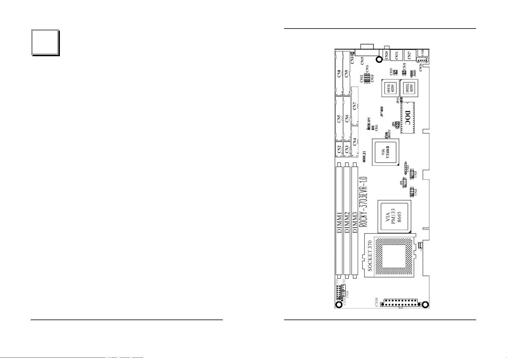
2.1 ROCKY – 3703EVR's Layout
7
8
Page 6

2.2 Unpacking Precautions
A
2.3 Setting the CPU of ROCKY-3703EVR
Some components on ROCKY-3703EVR SBC are very
sensitive to static electric charges and can be damaged by a
sudden rush of power. To protect it from unintended damage,
be sure to follow these precautions:
Ground yourself to remove any static charge before touching
your ROCKY-3703EVR SBC. You can do it by using a grounded
wrist strap at all times or by frequently touching any conducting
materials that is connected to the ground.
Handle your ROCKY-3703EVR SBC by its edges. Don’t touch
IC chips, leads or circuitry if not necessary.
Do not plug any connector or jumper while the power is on.
Table of Jumpers
LABEL FUNCTION
JP5 Watch-Dog Active Type Setting
JP7 Onboard LAN1 enable/disable.
JP8 CPU Multiplier Setting,Normal by AUTO detect.
JP9 DiskOnChip Memory Address Setting
JP10 Onboard LAN2 enable/disable.
JBAT1 CMOS state setting
Note:
ll shaded rows in tables of this manual are the default settings
for the ROCKY-3703EVR.
JP8 : CPU Multiplier Setting
•
Speed 1-2 3-4 5-6 7-8
3.0 x
3.5 x
4.0 x
4.5 x
5.0 x
5.5 x
6.0 x
6.5 x
7.0 x
7.5 x
8.0 x
CLOSE OPEN CLOSE CLOSE
CLOSE OPEN OPEN CLOSE
OPEN CLOSE CLOSE CLOSE
OPEN CLOSE OPEN CLOSE
OPEN OPEN CLOSE CLOSE
OPEN OPEN OPEN CLOSE
CLOSE CLOSE CLOSE OPEN
CLOSE CLOSE OPEN OPEN
CLOSE OPEN CLOSE OPEN
CLOSE OPEN OPEN OPEN
OPEN CLOSE CLOSE OPEN
PS: If Intel fixes CPU RATIO, the JP8 is no purpose.
2.4 Watch-Dog Timer (JP5)
Reading I/O port 443H enables the Watch-Dog Timer. It should
be triggered before the time-out period ends, otherwise it will
assume the program operation is abnormal and will issue a
reset signal to start again, or activate NMI to CPU. The WatchDog Timer is disable by reading I/O port 043H or 843H. Refer to
Appendix A for detailed information on Watch-Dog Timer.
• JP5 : Watch-Dog Active Type Setting
JP5 DESCRIPTION
1-2 ACTIVATE NMI TO CPU WHEN WDT TIME-
OUT
2-3 RESET WHEN WDT TIME-OUT
OPEN DISABLE WDT
9
10
Page 7
2.5 DiskOnChip™ Flash Disk (JP9)
The DiskOnChip™ Flash Disk Chip(DOC) is produced by MSystems. Because the DOC is 100% software compatible to
hard disk and DOS, users don‘t need any extra software utility. It
is just “plug and play” easy and reliable. At present the DOC is
available from 2MB to 144MB. The DiskOnChip only shares
• JP9 : DiskOnChip Memory Address Setting
8KB memory address.
Address 1-2 3-4 5-6
CE000 – CFFFF OFF ON ON
D6000 – D7FFF ON OFF ON
DE000 – DFFFF OFF OFF ON
2.6 Clear CMOS Setup (JBAT1)
If want to clear the CMOS Setup (for example forgot the
password you should clear the setup and then set the password
again.), you should close the JBAT1 (1-2) about 3 seconds,
then open it again. Set back to normal operation mode, open
JBAT1 : Clear CMOS Setup (Reserve Function)
JP1. •
JBAT1 DESCRIPTION
1-2 Normal Operation
2-3 Clear CMOS Setup
2.7 Onboard LAN1(JP7) / LAN2(JP10) Setting
The onboard LAN controllers can be disabled if you don’t want to use
then. All the hardware resource will be released. After they are disabled.
JP7/JP10 DESCRIPTION
CLOSE Enable
OPEN Disable
3
Connection
This chapter describes how to connect peripherals, switches
and indicators to the ROCKY- 3703EVR board.
Table of Connectors
LABEL FUNCTION
CN1 CPU Fan Connector
CN2,CN3 Serial Port 10-pin Connector
CN4 Parallel Port Connector
CN5 Primary IDE Connector
CN6 Secondary IDE Connector
CN7 FDC Connector
CN8,CN9 Promise IDE RAID Connector
CN10 Promise IDE RAID Active LED Connector
CN12 AUDIO LINE-IN
CN13 AUDIO CD-IN
CN14 AUDIO MIC-IN
CN15 VGA 15-pin Female Connector
CN16 ATX 20-PIN Power Connector
CN18,CN19 LAN State LED Connector
CN21,CN27 LAN RJ45 Connector
CN22 System Fan Connector
CN23,CN25 USB Connector
CN24 IrDA connector
CN26 External 5-pin Header Keyboard Connector
CN28 PS/2 MOUSE & KEYBOARD Connector
CN29 ATX BUTTON (Power ON) Switch
CN30 Backplane to Mainboard Connector
CN31 External Switches and Indicators
11
12
Page 8

3.1 Floppy Disk Drive Connector (CN7)
3.2 PCI E-IDE Disk Drive Connector (CN5, CN6)
The ROCKY-3703EVR board is equipped with a 34-pin daisychain drive connector cable.
CN7 : FDC Connector
•
PIN NO. DESCRIPTION PIN NO. DESCRIPTION
1 GROUND 2 REDUCE WRITE
3 GROUND 4 N/C
5 GROUND 6 N/C
7 GROUND 8 INDEX#
9 GROUND 10 MOTOR ENABLE A#
11 GROUND 12 DRIVE SELECT B#
13 GROUND 14 DRIVE SELECT A#
15 GROUND 16 MOTOR ENABLE B#
17 GROUND 18 DIRECTION#
19 GROUND 20 STEP#
21 GROUND 22 W RITE DATA#
23 GROUND 24 W RITE GATE#
25 GROUND 26 TRACK 0#
27 GROUND 28 W RITE PROTECT#
29 GROUND 30 READ DATA#
31 GROUND 32 SIDE 1 SELECT#
33 GROUND 34 DISK CHANGE#
You can attach four IDE( Integrated Device Electronics) hard
disk drives on two channels. These connectors support UltraDMA100 IDE devices. Non-DMA100 devices are suggested to
be connecting to the secondary IDE connector.
CN5 (IDE 1) : Primary IDE Connector
CN6 (IDE 2) : Secondary IDE Connector
CN5/CN6 : IDE Interface Connector
•
PIN NO. DESCRIPTION PIN NO. DESCRIPTION
1 RESET# 2 GROUND
3 DATA 7 4 DATA 8
5 DATA 6 6 DATA 9
7 DATA 5 8 DATA 10
9 DATA 4 10 DATA 11
11 DATA 3 12 DATA 12
13 DATA 2 14 DATA 13
15 DATA 1 16 DATA 14
17 DATA 0 18 DATA 15
19 GROUND 20 N/C
21 N/C 22 GROUND
23 IOW# 24 GROUND
25 IOR# 26 GROUND
27 N/C 28 BALE - DEF AULT
29 N/C 30 GROUND - DEFAULT
31 INTERRUPT 32 IOCS16#-DEFAULT
33 SA1 34 N/C
35 SA0 36 SA2
37 HDC CS0# 38 HDC CS1#
39 HDD ACTIVE# 40 GROUND
13
14
Page 9

3.3 Parallel Port (CN4)
This port is usually connected to a printer. The ROCKY3703EVR includes an on-board parallel port, accessed through
a 26-pin flat-cable connector CN4.
CN4 : Parallel Port Connector
•
PIN NO. D ESC RIPTION PIN NO. DESCRIPT ION
1 STROBE# 2 DATA 0
3 DATA 1 4 DATA 2
5 DATA 3 6 DATA 4
7 DATA 5 8 DATA 6
9 DATA 7 10 ACKNOWLEDGE
11 BUSY 12 PAPER EMPTY
13 PRINTER SELECT 14 AUTO FORM F EED #
15 ERROR# 16 INITIALIZE
17 PRINTER SELECT LN# 18 GROUND
19 GROUND 20 GROUND
21 GROUND 22 GROUND
23 GROUND 24 GROUND
25 GROUND
3.4 Serial Ports (CN2, CN3)
The ROCKY-3703EVR offers two high speeds NS16C550
compatible UART.
CN2 (COM1) : 10-pin header on board
CN3 (COM2) : 10-pin header on board
Serial port connections (CN2, CN3)
Connector Ports Address Interrupt
CN2 COM1 3F8 IRQ4
CN3 COM2 2F8 IRQ3
• Serial Port 10-pin Connector
PIN NO. DESCRIPTION
1 DATA CARRIER DETECT (DCD)
2 RECEIVE DATA (RXD)
3 TRANSMIT DATA (TXD)
4 DATA TERMINAL READY (DTR)
5 GROUND (GND)
6 DATA SET READY (DSR)
7 REQUEST TO SEND (RTS)
8 CLEAR TO SEND (CTS)
9 RING INDICATOR (RI)
10 GROUND (GND)
3.5 Keyboard & PS/2 Mouse Connector (CN28)
A 6-pin mini DIN connector (CN28) is located on the mounting
bracket for easy connection to a keyboard or a PS/2 mouse.
The card comes with a cable to convert from the 6-pin mini-DIN
connector to two 6-pin mini-DIN connectors for keyboard and
mouse connection.
CN28 : 6-pin Mini-DIN Keyboard Connector
•
PIN NO. DESCRIPTION
1 KEYBOARD DATA
2 MOUSE DATA
3 GROUND
4 +5V
5 KEYBOARD CLOCK
6 MOUSE CLOCK
For alternative application, a keyboard and a PS/2 mouse pin
header connector are also available on board, located on CN26
6 respectively.
CN26 : 5-pin Header Keyboard Connector
•
PIN NO. DESCRIPTION
1 KEYBOARD CLOCK
2 KEYBOARD DATA
3 N/C
4 GROUND
5 +5V
15
16
Page 10

3.6 External Switches and Indicators (CN31)
3.7 USB Port Connector (CN23, CN25)
There are several external switches and indicators for
monitoring and controlling your CPU board. All the functions are
in the CN31 connector.
CN31 : External Switches and Indicators
PIN DESCRIPTION PIN DESCRIPTION
Power
LED
1 +5V 2 Speaker
3 N/C 4 N/C
Speaker
5 GND 6 N/C
7N/C 8 +5V
9 GND 10 Reset Switch
11 GND 12 GND
Reset
button
13 IDE LED+ 14 IDE LED-
CN29 : 2-pin Header ATX BUTTON Connector
•
PIN NO. DESCRIPTION
1 ATX BUTTON
2 GND
CN30 : Backplane to Mainboard Connector
•
PIN NO. DESCRIPTION
1 5VSB
2 ATX-ON
3 GND
★ Power source from Backplane with ATX Connector
(Through Power Button & +5VSB)
The ROCKY- 3703EVR provide four built-in USB ports for the
future new I/O bus expansion.
CN23 / CN25
PIN NO. DESCRIPTION PIN NO. DESCRIPTION
1 VCC 8 VCC
2 DATA- 7 DATA3 DATA+ 6 DATA+
4 GROUND 5 GROUND
3.8 IrDA Infrared Interface Port (CN24)
The ROCKY-3703EVR has a built-in IrDA port which supports
Serial Infrared (SIR) or Amplitude Shift Keyed IR (ASKIR)
interface. If you want to use the IrDA port, you have to configure
SIR or ASKIR model in the BIOS under Peripheral Setup COM2.
Then the normal RS-232 COM 2 will be disabled.
• CN24: IrDA connector
PIN NO. DESCRIPTION
1 VCC
2 NC
3 IR-RX
4 Ground
5 IR-TX
6 NC
3.9 CPU & SYSTEM Fan Connector (CN1, CN22)
The ROCKY-3703EVR provides two CPU cooling fan
connectors, CN22 as well as a chassis fan connector, CN1.
These connectors can supply 12V/500mA to the cooling fan. All
connectors have the same pin assignments and provide a
"rotation" pin to get rotation signals from fans and notice the
system. So the system BIOS can recognize the fan speed.
Please note that only specified fan can issue the rotation signals.
• CN1/CN22 : Fan Connector
PIN NO. DESCRIPTION
1 Rotation S ign al
2 12V
3 Ground
17
18
Page 11

3.10 LAN RJ45 & State LED Connector (CN21,CN27)
The ROCKY-3703EVR is equipped with two built-in 10/100Mbps
Ethernet controllers. You can connect it to your LAN through
RJ45 LAN connectors. There are two LED on the connector
indicating the status of LAN. The pin assignments are as
following:
CN21/CN27: LAN RJ45 Connector
•
PIN NO. DESCRIPTION PIN NO. DESCRIPTION
1 TX+ 5. N/C
2 TX- 6. RX-
3. RX+ 7. N/C
4. N/C 8. N/C
• CN18/CN19: LAN State LED Connector
PIN NO. DESCRIPTION
1-2 ACT/LINK
3-4 100TX
3.11 VGA Connector (CN15)
The ROCKY-3703EVR has a built-in 15-pin VGA connector
directly connects to your CRT monitor.
• CN15 : 15-pin Female Connector
1 RED 2 G REEN
3 BLUE 4 NC
5 GROUND 6 GROUND
7 GROUND 8 GROUND
9 NC 10 GROUND
11 NC 12 DDC DAT
13 HSYNC 14 VSYNC
15 DDCCLK
3.12 PROMISE ATA-100 IDE RAID & Active LED
Connector
The ROCKY-3703EVR provides two IDE RAID connectors --.
Each port supports 2 IDE devices at 100Mbps speed. There are
also one connector indicating the status of the IDE RAID
channels.
• CN8(Channel 1)/CN9(Channel 2) : ATA-100 IDE RAID
Connector, 40-pin
PIN NO. DESCRIPTION PIN NO. DESCRIPTION
1 RESET# 2 GROUND
3 DATA 7 4 DATA 8
5 DATA 6 6 DATA 9
7 DATA 5 8 DATA 10
9 DATA 4 10 DATA 11
11 DATA 3 12 DATA 12
13 DATA 2 14 DATA 13
15 DATA 1 16 DATA 14
17 DATA 0 18 DATA 15
19 GROUND 20 N/C
21 N/C 22 GROUND
23 IOW# 24 GROUND
25 IOR# 26 GROUND
27 N/C 28 BALE - DEFAULT
29 N/C 30 G ROUND - DEFAULT
31 INTERRUPT 32 IOCS16#-DEFAULT
33 SA1 34 N /C
35 SA0 36 SA2
37 HDC CS0# 38 HDC CS1#
39 HDD ACTIVE# 40 G ROUND
• CN10: ATA-100 IDE RAID active LED connector.
3.13 AUDIO Headphone (CN20) & Connector
The ROCKY-3703EVR has a built-in AC’97 AUDIO CODEC;
connector directly connects to your MIC-IN & CD-IN & LINE-IN.
• CN20: AUDIO Headphone Jack (Output)
• CN12: AUDIO LINE-IN Connector (Input)
• CN13: AUDIO CD-IN Connector (Input)
• CN14: AUDIO MIC-IN Connector (Input)
PIN NO.
1 LEFT LEFT MIC-IN
2 GND GND GND
3 GND GND GND
4 RIGHT RIGHT NC
DESCRIPTION
CN12 CN13 CN14
19
20
Page 12

3.14 ATX 20-PIN Power Connector (CN16)
This connector supports the ATX power, functions such as
modem Ring on, wake-up LAN and soft power off are supported
by mainboard. (Power source from Mainboard)
PIN NO. DESCRIPTION PIN NO. DESCRIPTION
1 3.3V 2 3.3V
3 GND 4 5V
5 GND 6 5V
7 GND 8 PW_O K
9 5VSB 10 12V
11 3.3V 12 -12V
13 GND 14 A TX-ON
15 GND 16 GND
17 GND 18 -5V
19 5V 20 5V
4
AMI BIOS Setup
The ROCKY-3703EVR uses the AMI PCI/ISA BIOS for system
configuration. The AMI BIOS setup program is designed to
provide maximum flexibility in configuring the system by offering
various options, which may be selected for end-user
requirements. This chapter is written to assist you in the proper
usage of these features.
4.1 Getting Started
When powering on the system, the BIOS will enter the PowerOn-Self-Test (POST) routines. These routines will be executed
for system test, initialization and system configuration verification.
After the POST routines are completed, the following message
appears:
" Hit DEL if you want to run SETUP"
To access AMI PCI/ISA BIOS Setup program, press <Del> key.
The following screen will be displayed at this time.
21
22
Page 13

When choose Auto Configuration with Fail Safe Settings will
load the minimized settings for Troubleshooting. The
performance should be very poor when use this setting.
When choose Auto Configuration with Optimal Settings will
load optimized defaults for regular use. Choosing this setting will
modify all applicable settings.
4.2 Standard CMOS Setup
The Standard CMOS Setup is used for basic hardware system
configuration. The main function is for Date/Time setting and
Floppy/Hard Disk Drive setting. Please refer to he following
screen for this setup.
For IDE hard disk drive setup, please check the following
possible setup procedure,
1. Use the Auto setting for detection during boot up.
2. Use the IDE HDD AUTO DETECTION in the main menu to
automatically enter the drive specifications.
3. Manually enter the specifications by yourself from
the ”User“ option.
4.3 Advanced CMOS Setup
The Advanced CMOS Setup is designed for the user's tuning
best performance of the ROCKY-3703EVR board. As for
normal operation, users don‘t have to change any default
setting. The default setting is pre-set for most reliable operation.
Users can set “System Keyboard” to“ Absent” for the application
which don’t need keyboard and display.
23
24
Page 14

You can change the value of each option by using <PgUp> and
<PgDn> key. The available values are shown on the right
screen.
Quick Boot >
Enabled
: this will enable the BIOS to boot quickly
when you turn on your computer. The BIOS will only check the
first 1MB of the system memory.
Quick Boot >
Disabled:
the BIOS will test all system memory
when it boots up. It will spend about 40 seconds until it receives
a Ready signal from the HDD. It will also wait for you to press
the <Del> key or not.
st
1
, 2nd, 3rd Boot Device > to define the sequence of boot drives
after the routines check up completes. If the 1
the BIOS will attempt to boot from the 2
Try Other Boot Devices > the BIOS will try to boot from any
other available device in the system if the 1
st
nd
Boot Device fails,
or the 3rd device.
st
, 2nd and 3rd device
fails to boot.
Floppy Access Control > to define the read/write access which
is set when booting from a floppy drive.
S.M.A.R.T. for Hard Disks > to allow BIOS to use the System
Management and Reporting Technologies protocol for reporting
server system information on a network
BootUp Num-Lock > to turn on/off the Num-Lock option on an
enhanced keyboard when you boot. If you turn it off, the arrow
keys on the numeric keypad can be used just as the other set of
arrow keys on the keyboard and vice versa.
Floppy Drive Swap > this function enables you to swap the
floppy disk drives via software or without moving the hardware.
Floppy Drive Seek > when this option is turned Enabled, BIOS
will perform a Seek command on floppy drive A: before boot-up.
PS/2 Mouse Support > to testify whether or not a PS/2 mouse
is supported.
System Keyboard > to configure the keyboard. If you set it
Absent, BIOS will not report keyboard errors.
Password Check > to define if a password is necessary or not
for access to the BIOS setup.
Boot to OS/2 > if you run the OS/2 operating system, this option
must be set to yes. It means you permit BIOS to run properly if
OS/2 or any other OS that does not support Plug and Play is
found in your computer.
CPU Serial Number > this option is available only if you use
Pentium® III processor.
Cache Bus ECC > this option is available only if you use
Pentium® III processor.
System BIOS Cacheable > to define whether or not the
memory segment FOOOH can be read from or written to cache
memory. Setting it Enabled will give faster execution in your
system.
Hard Disk Access Control > to define the read/write access
which is set when booting from a HDD.
25
4.4 Advanced Chipset Setup
These setup functions mainly working for Chipset (Intel 440BX).
These options are used to change the Chipset‘s registers.
26
Page 15

Please carefully change any default setting, otherwise the
system may become unstable.
Configure SDRAM Timing by SPD > The Serial Presence
Detect is a 2048bits EEPROM which contains of the data of the
chip module, capacity, timing, voltage, etc. The system will
configure the SDRAM timing according to the data in the SPD
when it is set enabled.
SDRAM CAS# Latency > to specify the CAS latency timing
form SDRAM DRAM.
Memory Hole > to specify the location of a memory hole in the
CMOS RAM. This setting reserves 15MB to 16MB memory
address space for ISA expansion cards that specifically require
this setting. Memory from 15MB and up will be unavailable to
the system because expansion cards can only access memory
up to 16MB.
AGP Mode >
performance.
AGP Fast Write > The setting can adjust AGP driving of signal,
AGP will have the best performance and compatibility.
Enabled 4X
will give you better system
AGP Aperture Size > to define the size of Graphics Aperture.
AGP Master 1 W/S Write>System will run single wait state
delay before write data from buffer, if user set to "Disable"
system will run twice wait states, so system can stable
AGP Master 1 W/S Read> System will run single wait state
delay before read data from buffer, if user set to "Disable"
system will run twice wait states, so system can stable
USB Passive Release > to specify whether or not PIIX4 is
allowed to use Passive Release while transferring control data
for USB transactions.
USB Function > to enable or disable the USB (Universal Serial
Bus) functions.
ATX Power Supply Controller > to Enable or Disable ATX
Power Supply
4.5 Power Management Setup
Power Management Setup helps user handle the ROCKY3703EVR board‘s “green” function. The features could shut
down the video display and hard disk to save energy for
example. The power management setup screen is as following:
27
28
Page 16

Video Power Down Mode > to specify the power state of the
VESA VGA video subsystem after the specified period of
display-idle has ended.
Hard Disk Power Down Mode > to specify the power state of
the hard disk after the specified period of hard drive-idle has
ended.
Standby Time Out (Minute) > to specify the length of the
system-idle period while the system is in full power on state.
After this period of time has ended, the system will go into
Standby state.
Suspend Time Out (Minute) > to specify the length of the
system-idle period while the system is in Standby state. After this
period of time has ended, the system will go into Suspend state.
ACPI Standby State: S1/POS, S3/STR
This item allows you to select power Management ACPI mode.
Power Management/APM: Disable, Max Saving, Min Saving,
or User Defined > Max Saving puts the system into power
saving mode after a brief inactivity period. Min Saving is almost
the same as Max Saving except that the inactivity period is
longer. User Defined allows you to set power saving options
according to your requirement.
Note: Advanced Power Management (APM) has to be
installed to keep the system time updated when the computer
enters suspend mode activated by the Power Management.
Under DOS environment, you need to add
DEVICE=C:\DOS\POWER.EXE in your CONFIG.SYS
Under Windows 3.x and Windows 95, you have to install
Windows with APM feature. A battery and power cord icon
labeled “Power” will appear in the “Control Panel”
Power Management/APM > to enable or disable the Advanced
Power Management feature.
Throttle Slow Clock Ratio > to specify the speed of system
clock under power saving state. The figure is a ratio between
power conserving and normal state CPU clock.
Modem Use IO Port > to assign a port for modem.
Modem Use IRQ > to assign an IRQ for modem
Display Activity > to specify if BIOS has to monitor display
activity or not.
Device X > to monitor specified device IRQ or Ignore.
Power Button Function > to specify how the powers button on
the chassis is operated.
4.6 Peripheral Setup
These setup mainly works for Multi-I/O Chip (W83977TF).
These options are used to change the Chipset‘s registers.
Please carefully change any default setting to meet your
application need perfectly. The only special concern is Onboard
Serial Port B. if you are using the IrDA port; you have to set this
port accordingly.
29
30
Page 17

Onboard FDC > to enable the FDC on your board. If you set it
Auto, the BIOS will decide if the FDC should be enabled,
automatically).
Onboard Serial Port A (/B) > to specify the I/O port address of
the serial port A (/B). If you set it Auto, the BIOS will decide the
correct I/O port address, automatically.
Serial Port B Mode > to specify the mode of serial port B.
IR Duplex Mode > to specify the mode of IR device that is
connected to the IR port.
ECP
(supports devices that comply with the Extended
Ca pabil ities Port) .
Parallel Port IRQ > to assign certain IRQ to the parallel port.
The optimal and fail-safe settings are 7.
Parallel Port DMA Channel > available only if the parallel port
mode is ECP. The optimal and fail-safe settings are 3.
Onboard IDE > to define which on-board IDE controller
channel(s) to be used. Available options are primary, Secondary,
Both and Disabled.
4.7 PCI / PLUG AND PLAY SETUP
The setup helps users handle the ROCKY-3703EVR board‘s
“PCI” function. All PCI bus slots on the system use INTA#, thus
all installed PCI slots must be set to this value.
IrDA Protocol > to specify the function mode if an IrDA mode is
selected.
Onboard Parallel Port > to specify the I/O port address of the
parallel port.
Parallel Port Mode > to specify the mode of parallel port. The
options are:
Normal
Bi-Dir
EPP
Port spe cification),
31
(normal parallel port mode),
(supports bi-directional transfer),
(supports devices that comply with the Enhanced Parallel
32
Plug and Play Aware O/S > Yes or No
When PnP OS is installed, the OS may reassign interrupts when
the setting is “Yes”. When a non-PNP OS is installed or to
prevent reassigning of interrupt settings, select setting to “No”.
Page 18

Plug and Play Aware O/S > Yes or No
When PnP OS is installed, the OS will reassign interrupts when
the setting is “Yes”. When a non-PNP OS is installed or to
prevent reassigning of interrupt settings, select setting to “No”.
Clear NVRAM > if
boot.
On Board PCI SCSI Controller > to enable and disable the on
board PCI SCSI Controller
PCI Latency Timer (PCI Clocks) > to define the latency timing
(PCI clock) for all PCI devices on the PCI bus.
PCI VGA Palette Snoop > this option is useful only for system
with more than one VGA devices connected to it through
different bus (one PCI and one ISA). To enable those various
VGA devices to handle signal from the CPU on each set of
palette registers of every video devices, it must be set
Allocate IRQ to PCI VGA > to allocate IRQ to PCI VGA, answer
Yes and vice versa.
Offboard PCI IDE Card > to specify if an off board PCI IDE card
is installed in your computer or not. You must specify the slot
number on the board, which will be used for the card.
Offboard PCI IDE Primary (/Secondary) IRQ > to specify the
PCI interrupt that is assigned to the Primary (/Secondary) IDE
channel on the offboard PCI IDE controller.
PCI Slot (1,2,3,4) IRQ Priority > to specify the IRQ priority to be
used by the PCI devices on slot 1 to 4.
DMA Channel (0,1,3 ,5,6,7) > to indicate whether or not the DMA
channel is assigned for a PnP or ISA card.
IRQ (3,4,5,7,9,10,11,14,15) > to assign the displayed IRQ to be
used by a legacy ISA adapter card. The settings are ISA/EISA or
PCI/PnP.
yes
, BIOS will auto-clear NVRAM on every
Enabled
.
4.8 Hardware Monitor Setup
This setup helps users monitor the ROCKY-3703EVR boards
on board system voltage and fan speed. The function is
implemented by on board VIA686 chip. The voltage monitoring
will cover +5V, +12V,-12V,and –5V. And there are three fan
connectors for chassis and CPU fans.
Note: normal CPU Fan RPM is over than 5000 RPM. If your
CPU Fan RPM is less than that figure, something is wrong and
the CPU will be in overheat condition. Make sure that the
connection at CN1/CN22 is correct.
33
34
Page 19

5
Example assembly program:
TIMER_PORT = 443H
TIMER_START = 443H
Appendix A. Watch-Dog Timer
The WatchDog Timer is a device to ensure that standalone systems can
always recover from abnormal conditions that cause the system to
crash. These conditions may result from an external EMI or a software
bug. When the system stops working, hardware on the board will
perform hardware reset (cold boot) to bring the system back to a known
Three I/O ports control the operation of WatchDog Timer.
state.
443 (hex) Write Set WatchDog Time period
443 (hex) Read Enable the refresh the WatchDog Timer.
043/843 (hex) Read Disable the WatchDog Timer.
Prior to enable the WatchDog Timer, user has to set the time-out period.
The resolution of the timer is 1 second and the range of the timer is from
1 sec to 255 sec. You need to send the time-out value to the I/O port –
443H, and then enable it by reading data from the same I/O port – 443H.
This will activate the timer that will eventually time out and reset the CPU
board. To ensure that this reset condition won’t occur, the WatchDog
Timer must be periodically refreshed by reading the same I/O port 443H.
This must be done within the time-out period that is set by the software,
please refer to the example program. Finally, we have to disable the
WatchDog timer by reading the I/O port -- 843H or 043H. Otherwise the
system could reset unconditionally.
A tolerance of at least 5% must be maintained to avoid unknown
routines in the operating system (DOS), such as disk I/O that can be
very time-consuming. Therefore if the time-out period has been set to 10
seconds, the I/O port 443H must be read within 7 seconds.
TIMER_STOP = 843H
;;INITIAL TIMER C OUNT ER
MOV DX, TIMER_PORT
MOV AL, 8 ;;8 seconds
OUT DX, AL
MOV DX, TIMER_START
IN AL, DX. ;;START COUNTER
W_LOOP:
MOV DX, TIMER_STOP
IN AL, DX
MOV DX, TIMER_START
IN AL, DX ;;RESTART COUNTER
;;ADD YOUR APPLICATION HERE
CMP EXIT_AP, 0
JNE W_LOOP
MOV DX, TIMER_STOP
35
IN AL, DX
;;EXIT AP
36
Page 20

Appendix B. I/O Address Map
• I/O Address Map
I/O Address
Description
Map
000-01F DMA Controller #1
020-021 Interrupt Controller # 1, Master
040-05F System Timer
060-06F Standard 101/102 keyboard Controller
070-07F Real time Clock, NMI Controller
080-0BF DMA Page Register
0A0-0BF Interrupt Controller # 2
0C0-0DF DMA Controller # 2
0F0-0F0 Clear Math Coprocessor Busy
0F1-0F1 Reset Math Coprocessor
0F8-OFF Math Coprocessor
170-1F7 BUS Master PCI IDE Controller
278-27F Parallel Printer Port 2
2F8-2FF Serial Port 2
294-297 PCI bus
376-376 BUS Master PCI IDE Controller
378-37F Parallel Printer Port 1
3B0-3DF Standard AGP Graphic Adapter
3F0-3F7 Floppy Disk Controller
3F8-3FF Serial Port 1
443 Watch dog timer enable
843/043 Watch dog timer disable
1 st MB Memory Address Map
Memory address Description
00000-9FFFF SYSTEM MEMORY
A0000-BFFFF VGA BUFFER
C0000-C7FFF VGA BIOS
C8000-CFFFF NO USE
D6000-D7FFF DEFAULT DOC2000 ADDRESS
E0000-FFFFF SYSTEM BIOS
100000 EXTEND MEMORY
IRQ Mapping Chart
IRQ0 System Timer IRQ8 RTC clock
IRQ1 Keyboard IRQ9 SCSI PORT A
IRQ2 IRQ Controller IRQ10 LAN
IRQ3 COM2 IRQ11 IDE RAID
IRQ4 COM1 IRQ12 PS/2 mouse
IRQ5 LAN IRQ13 FPU
IRQ6 FDC IRQ14 Primary IDE
IRQ7 Printer IRQ15 Secondary IDE
DMA Ch anne l Ass ignment
Channel Function
0 Available
1 Available
2 Floppy disk
3 Available
4 Cascade for DMA controller 1
5 Available
6 Available
7 Available
37
38
Page 21

Appendix C. ATX Power Supply
The following notes show how to connect ATX Power Supply to the
backplanes and / or the ISBC card.
A. For backplanes with ATX Connector
1. Please, disconnect the AC cord of the Power Supply from the AC
source to prevent sudden electric surge to the board.
2. Please, check the type of your CPU board. All CPU board listed on
the next page support ATX power supply but has two types of
power switch connection:
2.1. ROCKY-3703EVR (through Power Button & GND):
Connect the ATX power button switch to the CN29 (power
button). And connect the power cable from Backplane to CN30
of CPU card.
If you want to turn ON the system, just press the button once.
And if you want to turn off the power supply, please press the
ATX power switch button for about 4 seconds.
B. For the backplanes with ATX power supply
connector
For some SBC without ATX power ON/OFF function, then you can
control the ATX power supply through backplane’s PS ON
connector. Refer to the figure below: for the backplanes with ATX
connector, the connection can be made simply as following:
1. Connect the ON/OFF (ordinary one) switch to Pin 2 (PS ON) and
Pin 3 (GND) of connector CN2
2. You may now turn the power ON/OFF by the power switch
39
40
Page 22

Appendix D. How to use Wake-Up Function
The ROCKY-3703EVR provides two kind of Wake up Function.
This page describes how to use Modem Wake-Up and LAN Wake-Up
function.
Wake-Up function is working while you use ATX power supply,
Wake-Up By Ring:
You must set the option Power On By Ring of CMOS SETUP to be
enabled. The ATX power supply will be switched on when there is a ring
signal detected on pin “RI” of serial port.
Wake-Up On LAN:
When your computer is in power-down status, you can see LAN
Link/Active LED is flashing. This status indicates that the LAN chip has
entered standby mode and waits for Wake-Up signal. You can use other
computers to wake up your computer by sending ID to it.
: ID is the address of your system LAN. Every LAN chip has a factory-
ID
set ID, which you can find it from network information in WINDOWS.
ID’s f ormat is xxxxxxxxxxxx
Example ID: 009027388320
Appendix E. RAID FastTrak100
1. Introduction
Promise designed its FastTrak100 to provide a cost-effective, high
performance RAID that adds performance and/or reliability to PC
desktops and/or servers using Ultra ATA/100, Ultra ATA/66, or EIDE
drives.
FastTrak100 supports striping (RAID 0), mirroring (RAID 1),
striping/mirroring (RAID 0+1), or spanning (JBOD) operation,
respectively.
With striping, identical drives can read and write data in parallel to
increase performance. Mirroring increases read performance through
load balancing and elevator sorting while creating a complete backup of
your files. Striping with mirroring offers both high read/write performance
and error tolerance. Spanning uses the full capacity of all attached
drives without requiring identical drive size, but offers no other RAID
functionality.
A FastTrak100 striped array can double the sustained data transfer rate
of Ultra ATA/66 drives. FastTrak100 fully supports Ultra ATA/100
specification of up to 100 MB/sec per drive, depending on individual
drive specifications.
FastTrak100 also offers fault tolerant, data redundancy for entry-level
network file servers or simply for desktop PC users wanting to
continually protect valuable data on their PC. FastTrak100 offers RAID 1
mirroring (for two drives) and RAID 0+1 mirroring and striping (for four
drives) to protect data. Should a drive that is part of a mirrored array fail,
FastTrak100 uses the mirrored drive (which contains identical data) to
assume all data handling. When a new replacement drive is later
installed, FastTrak100 rebuilds data to the new drive from the mirrored
drive to restore fault tolerance.
41
42
Page 23

FastTrak100's bootable BIOS supports individual drives larger
than 8.4GB. With FAT32 and NTFS partitioning, the array can
be addressed as one large single volume.
The FastTrak100 controller provides two IDE hard drive
connectors that support Ultra ATA/100 protocols, perfect for
such demanding applications as real-time video, multimedia,
and high-performance operating systems. FastTrak100’s two
IDE connectors each support a master/slave combination of any
IDE devices, including IDE, EIDE, Fast-ATA, and Ultra-ATA
standards. Devices of different standards can be connected to
FastTrak100 without performance degradation, due to the
independent programmable timing registers in the controller’s
design.
2. Software Installation
This section details the FastTrak100 driver installation
procedure when used with various operating systems as follows:
· Windows 2000
· Microsoft Millenium
· Windows 98
· Windows NT 4.x
. Linux
You can install from CDROM drive or copy it to disk from
CDROM.
2-1 Windows 2000
2-1-1 Installing Driver during New Windows 2000
Installation
1a. Floppy Install: Boot the computer with the Windows 2000
installation diskettes.
1b. Floppyless Install: Boot from floppy and type “WINNT”. After
files have been copied, the system will reboot. On the reboot,
press <F6> after the message “Setup is inspecting your
computer’s hardware configuration...” appears.
1c. CD-ROM Install: Boot from the CD-ROM. Press <F6> after
the message “Press F6 if you need to install third party SCSI or
RAID driver” appears.
2. When the “Windows 2000 Setup” window is generated, press
“S” to Specify an Additional Device(s)
3. Press “O” to select “Other” and press the “Enter” key.
4. Insert the Promise Technology driver diskette into drive A:
and
press “Enter” key.
5. Choose “Win2000 Promise FastTrak100 Controller” from the
list that appears on screen, and then press the “Enter” key.
6. The Windows 2000 Setup screen will appear again saying,
“Setup will load support for the following mass storage devices:”
The list will include “Win2000 Promise FastTrak100 controller”.
NOTE: If you need to specify any additional devices to be
installed, do so at this time. Once all devices are specified,
Continue to step 6.
7. From the Windows 2000 Setup screen, press the Enter key.
Setup will now load all device files and then continue the
Windows 2000 installation.
2-1-2 Installing Driver in Existing Windows 2000 System
WARNING: If you will be moving the boot drive containing the
existing Windows 2000 operating system to the FastTrak100
card, the Ultra100 driver MUST be loaded on to this hard drive
while it is still attached to your existing hard drive controller. Do
not attach this drive or any other hard drive to the FastTrak100
controller card before completing this step. After installing the
FastTrak100 card and rebooting your system, Windows 2000
setup will show a “New Hardware Found” dialog box.
1. In the dialog box, choose “Driver from disk provided by
hardware manufacturer” button.
2. In the A: drive, insert the FastTrak100 driver diskette.
3. Type “A:\WIN2000” in the text box. Press “Enter”.
4. Choose “Win2000 Promise FastTrak100 IDE Controller” from
the list that appears on screen, and then press the “Enter” key.
5. The Windows 2000 Setup screen will appear again saying,
“Setup will load support for the following mass storage
devices – Win2000 Promise FastTrak100 IDE controller”. The
FastTrak100 driver will now be copied on to the system and
entered into the Windows 2000 driver database.
6. When the “System Settings Change” dialog box appears,
remove the floppy diskette and click on “Yes” to restart the
system. Windows 2000 will then restart for the driver installation
to take effect.
7. Power off your system, then attach your hard drive to the
FastTrak100 controller.
Confirming Windows 2000 Installation
1. From Windows 2000, open the Control Panel from “My
43
44
Page 24

Computer” followed by the System icon.
2. Choose the “Hardware” tab, and then click the “Device
Manager” tab.
3. Click the “+” in front of “SCSI controllers.” “Promise
Technology, Inc. FASTTRAK100 IDE controller” should appear.
2-2 Microsoft Millennium
2-2-1 Installing Drivers during Millennium Installation
The following details the installation of the FastTrak100 drivers
while installing Microsoft’s Millennium (with the FastTrak100
controller card already in place). If you’re installing the
FastTrak100 drivers on a system with Millennium already
installed, see “Installing Drivers with Existing Millennium
System.”
1. Install Microsoft Millenium fully.
2. After installation, go the “Start” menu and choose “Settings.”
3. From the “Settings” menu, choose “Control Panel.”
4. In the “Control Panel” window, double-click on the “System”
icon.
5. In the “System” window, choose the “Device Manager” tab.
6. In the hierarchical display under “Other Devices” is a listing for
“PCI Mass Storage Controller.” Choose it and then press the
“Properties” button.
7. Choose the “Driver” tab in the “Properties” window, choose
“Update Driver,” and then press “Next.”
8. Choose “Search for a better driver than the one your device is
using now (recommended),” then press “Next.”
9. Choose “Specify Location,” then type “A:\WINMILL” in the text
box.
10. Insert the “Fa stTrak100 Driver” diskette into drive A:.
11. Press the “Next” button. A message informing you that
Millennium has found “Windows Millennium Promise
FASTTRAK100 (tm) IDE Controller” should appear.
12. Press “Next,” then “Finish,” then “Yes” when asked if you
want to restart your computer. Be sure to remove the diskette
from drive A:.
2-2-2 Installing Drivers with Existing Millenium System
The following section details the installation of FastTrak100
drivers on a system that has Millenium already installed and
running. If you’re installing the FastTrak100 drivers on a system
during an installation of Millenium, see “Installing Drivers During
Millenium Installation.”
1. After installing the FastTrak100 controller card and
configuring the hard drives, power up the system and boot.
2. The “Add New Hardware Wizard” will appear, informing you
that it has found a “PCI Mass Storage Controller.”
3. Click on “Next,” and from the generated list box, choose
“Search for a better driver than the one your device is using
now.”
4. Click on “Next,” and from the generated choices, choose
“Specify a location.”
5. Insert the “FastTrak100 Driver” diskette in drive A:.
6. Type “A:\WINMILL” in the text box that appears.
7. Click on “Next.” A message informing you that Millennium has
found “Windows Millennium Promise FASTTRAK100 (tm) IDE
Controller” should appear.
8. Click on “Next” and then on “Finish”.
9. Choose “Yes” when asked if you want to restart your
computer.
Be sure to eject the diskette from drive A:.
Confirming Driver Installation in Millennium
To confirm that the driver has been properly loaded in
Millennium,
perform the following steps:
1. Choose “Settings” from the “Start” menu.
2. Choose “Control Panel,” and then double-click on the
“System”
icon. Choose the “Device Manager” tab, and then click the “+” in
front of “SCSI controllers.” “Windows Millennium Promise
FASTTRAK100 (tm) IDE controller” should appear.
2-3 Windows 98
5.2-3-1 Installing Drivers During Windows 98 Installation
The following details the installation of the FastTrak100 drivers
while installing Windows 98 (with the FastTrak100 controller
card already in place). If you’re installing the FastTrak100
drivers on a system with Windows 98 already installed, see
“Installing Drivers with Existing Windows 98.”
1. After installing the FastTrak100 controller card and
configuring the hard drive(s) partition and format your hard
drive(s), if necessary.
45
46
Page 25

2. Install Windows 98 normally.
3. After installation, go the “Start” menu and choose “Settings.”
4. From the “Settings” menu, choose “Control Panel.”
5. In the “Control Panel” window, double-click on the “System”
icon.
6. In the “System” window, choose the “Device Manager” tab.
7. In the hierarchical display under “Other Devices” is a listing for
“PCI Mass Storage Controller.” Choose it and then press the
“Properties” button.
8. Choose the “Driver” tab in the “Properties” window, choose
“Update Driver” and then press “Next”.
9. Choose “Search for a better driver than the one your device is
using now (recommended),” then press “Next.”
10. Choose “Specify Location,” and then type “A:\WIN95-98” in
the text box.
11. Insert the “FastTrak100 Driver” diskette into the drive A:.
12. Press the “Next” button. A message informing you that
Windows has found “Win95-98 Promise FASTTRAK100 (tm)
IDE Controller” should appear.
13. Press “Next,” then “Finish,” then “Yes” when asked if you
want to restart your computer. Be sure to remove the diskette
from drive A:.
2-3-2 Installing Drivers with Existing Windows 98
The following section details the installation of FastTrak100
drivers on a system that has Windows 98 already installed. If
you’re installing the FastTrak100 drivers on a system during a
Windows 98 installation, see “Installing Drivers During Windows
98 Installation.”
1. After installing the FastTrak100 controller card and
configuring the hard drives, power up the system and boot
Windows.
2. The “Add New Hardware Wizard” will appear, informing you
that it has found a “PCI Mass Storage Controller.”
3. Click on “Next,” and from the generated list box, choose
“Search for a better driver than the one your device is using
now.”
4. Click on “Next,” and from the generated choices, choose
“Specify a location.”
5. Type “A:\WIN95-98” in the text box that appears.
6. Insert the “FastTrak100 Driver” diskette in drive A:.
7. Click on “Next.” A message informing you that Windows has
found “Win95-98 Promise FASTTRAK100 (tm) IDE Controller”
should appear.
8. Click on “Next” and then on “Finish”.
9. Choose “Yes” when asked if you want to restart your
computer.
Be sure to eject the diskette from drive A:.
Confirming Driver Installation in Windows 98
To confirm that the driver has been properly loaded in Windows
98, perform the following steps:
1. Choose “Settings” from the “Start” menu.
2. Choose “Control Panel,” and then double-click on the
“System”
icon.
3. Choose the “Device Manager” tab, and then click the “+” in
front of “SCSI controllers.” “Win95-98 Promise FASTTRAK100
(tm) IDE controller” should appear.
2-4 Windows NT 4.x
2-4-1 Installing Drivers During New Windows NT 4.0
Installation
1. Start the system installation by booting from the Windows NT
disk:
a) Floppy install: boot the system with the Windows NT
installation diskettes.
b) Floppyless install: boot from floppy and type “WinNT /B”.
After files have been copied, the system will reboot. On the
reboot, press the “F6” key when the message “Setup is
inspecting your computer’s hardware configuration…” appears.
c) CD-ROM disk install: boot from the CD-ROM disk and press
the “F6” key when the message “Setup is inspecting your
computer’s hardware configuration…” appears.
2. When the “Windows NT Setup” window is generated, press
“S”
to Specify an Additional Device(s).
3. Press “O” to select “Other” and press the “Enter” key.
4. Insert the Promise Technology driver diskette into drive A:
and
press the “Enter” key.
5. Choose “WinNT Promise FastTrak100 (tm) Controller” from
the list that appears on screen, and then press the “Enter” key.
6. The Windows NT Setup screen will appear again saying,
“Setup will load support for the following mass storage devices:”
47
48
Page 26

The list will include “Win2000 Promise FastTrak100 (tm)
controller”.
NOTE: If you need to specify any additional devices to be installed, do so at this time. Once all devices are specified,
continue to step 6.
7. From the Windows NT Setup screen, press the Enter key.
Setup will now load all device files and then continue the
Windows NT installation.
8. After a successful installation, the “SCSI Adapter Setup” box
will show that the “WinNT Promise FastTrak100 (tm) Controller”
driver has been installed.
2-4-2 Installing Drivers with Existing Windows NT 4.0
WARNING: If you wish to use your current bootable drive with
the
Windows NT4 operating system on the FastTrak100, perform
the steps below while the boot drive is still attached to your
existing onboard IDE controller. Do not attach any drives to your
FastTrak100 until the steps below are complete.
1. Choose “Settings” from the “Start” menu.
2. Choose “Control Panel” from the “Settings” menu.
3. Double-click on the “SCSI Adapters” icon, which generates
the
“SCSI Adapters” dialog box.
4. Choose “Drivers,” and then press “Add.”
5. In the “Install Drivers” dialog box, press “Have Disk…”
6. When the “Install from Disk” appears, insert the “FastTrak100
Driver” diskette in drive A:.
7. Type “A:\NT4” in the text box, and then choose “OK.”
8. When the “Install Driver” dialog box appears, select “WinNT
Promise FastTrak100 (tm) Controller” and then press “OK.”
9. When the “Select SCSI Adapter Option” dialog box appears,
press “Install.”
10. After a successful installation, the “SCSI Adapter Setup” box
will show that the “WinNT Promise FastTrak100 (tm) Controller”
driver has been installed.
11. Power off your system, and then attach your hard drive(s) to
the FastTrak100 controller.
3. FastTrack100 BIOS Utility
Creating Your Disk Array
You will now use the onboard FastBuild BIOS utility to create your array
using the attached drives. There are three different scenarios in creating
this array. You can create an array for performance, you can create a
Security array using new hard drives (recommended), or you can create
a Security array using an existed hard drive and a new hard drive.
1. Boot your system. If this is the first time you have booted with the
FastTrak100 card and drives installed, the Promise onboard BIOS
will display the following screen.
FastTrak100 (tm) BIOS Version 1.xx (Build xxxx)
(c) 1995-2000 P romise Technology, Inc. All R ights Reserved.
No array defined . . .
Press <Ctrl-F> to enter FastBuild (tm) Utility
Or press <ESC> key to continue booting the system.
2. Press <Ctrl-F> keys to display the FastBuild (tm) Utility Main Menu
3. Press “1” to display the Auto Setup Menu below. This is the fastest
and easiest method to creating your first array.
49
50
Page 27

FastBuild (tm) Utility 1.xx (c) 1995-2000 Promise Technology, Inc.
[Auto Setup Options Menu]
...................................................................................................
Optimize Array for: Performance
Typical Application usage: A/V Editing
[ Auto Setup Configuration ]
Mode.................................................... Stripe
Drives used in Array.....................................2
Array Disk Capacity .............................16126
[ Keys Available ]
[↑] Up [↓] Down [←, →, Space] Change Option [ESC] Exit [Ctrl-Y] Save
NOTE: If you wish to customize certain settings at a later time, you
may do so by manually creating your array (see page70 in Using
FastBuild Configuration Utility).
Creating an Array for Performance
NOTE: FastTrak100 allows users to create striped arrays with 1, 2, 3,
or 4 drives.
To create an array for best performance, follow these steps:
1. Using the Spacebar, choose “Performance” under the Optimize
Array for section.
2. Select how you will use your PC most under the Typical
Application usage section the choices are A/V Editing, Server, and
Desktop (the default).
3. Press <Ctrl-Y> keys to Save and create the array.
4. Reboot your system.
5. Once the array has been created, you will need to FDISK and
format the array as if it were a new single hard drive.
6. Proceed to Installing Drivers section of the manual
Creating a Security Array With New Drives
NOTE: FastTrak100 permits only two drives to be used for a
single Mirrored array in Auto Setup. If more drives are
physically attached to the card, the Mirroring option will not
be available at all in Auto Setup.
51
To create an array for data protection using new hard drives, follow
these steps:
1. Using the Spacebar, choose “Security” under the Optimize Array
for section.
2. Press <Ctrl-Y> keys to save your selection.
3. The window below will appear.
Do you want the disk image to be duplicated to another?
Y - Create and Duplicate
(Yes/No)
N - Create Only
52
Page 28

4. Press “N” for the Create Only option.
5. A window will appear almost immediately confirming that your
Security array has been created. Press any key to reboot the system
Array has been created.
<Press Any Key to Reboot>
Creating a Security Array with an Existing Data Drive
NOTE: FastTrak100 permits only two drives to be used for a single
Mirrored array in Auto Setup. If more drives are physically attached to
the card, the Mirroring option will not be available.
You would use this method if you wish to use a drive that already
contains data and/or is the bootable system drive in your system. You
will need another drive of identical or larger storage capacity.
6. Proceed with normal FDISK and format procedures as if you had
just installed a new hard drive.
7. Once the arrayed drives have been formatted proceed to the
Installing Driver chapter on page 46 to install your operating
system and/or FastTrak100 driver.
WARNING: Backup any necessary data before
proceeding. Failure to follow this accepted PC practice
could result in data loss.
WARNING: If you wish to include your current bootable
drive using the Windows NT 4.x or Windows 2000
operating system as part of a bootable Mirrored (RAID 1)
array on your FastTrak100, do NOT connect the hard
drive to the FastTrak100 controller yet. You MUST install the Windows
NT4 or 2000 driver software first (see page 46) to this drive while it is
still attached to your existing hard drive controller. For all other
Operating Systems, proceed here.
Follow these steps:
1. Using the Spacebar, choose “Security” under the Optimize Array
for section.
2. Press <Ctrl-Y> keys to save your selection. The window below will
appear.
53
Do you want the disk image to be duplicated to another?
Y - Create and Duplicate
(Yes/No)
N - Create Only
54
Page 29

3. Press “Y” for the Create and Duplicate option. The window below
will appear asking you to select the Source drive to use. FastBuild
will copy all data from the Source drive to the Target drive.
Channel:ID Drive Model Capacity (MB)
Channel:ID Drive Model Capacity (MB)
Channel:ID Drive Model Capacity (MB)
1 :Master QUANTUMCR8.4A 8063
2 :Master QUANTUMCR8.4A 8063
[↑] Up [↓] [ESC] Exit [Ctrl-Y] Save
Source Disk
Target Disk
[Please Select A Source Disk]
4. Use the arrow keys to choose which drive contains the existing data
to be copied.
5. Press [Ctrl-Y] keys to Save selection and start duplication. The
following progress screen will appear.
Start to duplicate the image . . .
Do you want to continue? (Yes/No)
Y – Continue N - Abort
6. Select “Y” to continue. If you choose “N”, you will be returned to step
1.
7. Once complete, the following screen will appear confirming that
your Security array has been created. Press any key to reboot the
system
Array has been created.
<Press Any Key to Reboot>
8. Proceed to the Installing Driver chapter on page 46 to install the
FastTrak100 driver and/or operating system.
4. Using FastBuild™ Configuration Utility
The FastBuild
create and manage the drive array on the Promise FastTrak100 adapter.
For purposes of this manual, it is assumed you have already created an
array in the previous chapter and now wish to make a change to the array
or view other options.
Viewing FastTrak100 BIOS Screen
When you boot your system with the FastTrak100 card and drive
installed the Promise onboard BIOS will detect the drives attached and
show the following screen.
(c) 1995-2000 Promise Technology, Inc. All Rights Reserved.
Scanning IDE drives . . . . .
If an array exists already, the BIOS will display the following screen
showing the BIOS version and status of the array.
(c) 1995-2000 Promise Technology, Inc. All Rights Reserved.
ID MODE SIZE TRACK-MAPPING STATUS
1 * 2+0 Stripe 16126M 611/128/32 Functional
Press <Ctrl-F> to enter FastBuild (tm) Utility....
The array status consists of three possible conditions: Functional,
Critical, and Offline.
TM
Configuration Utility offers several menu choices to
FastTrak100 (tm) BIOS Version 1.xx (Build xxxx)
FastTrak100 (tm) BIOS Version 1.xx (Build xxxx)
55
56
Page 30

Functional - The array is operational.
Critical - A mirrored array contains a drive that has failed or
disconnected. The remaining drive member in the array is functional.
However, the array has temporarily lost its ability to provide fault
Using the Main Menu
This is the first option screen when entering the FastBuildTM
Setup.
tolerance. The user should identify the failed drive through the
FastBuild Setup utility, and then replace the problem drive.
Offline - A mirrored array has 2 drives that have
FastBuild (tm) Utility 1.xx (c) 1995-2000 Promise Technology, Inc.
[ Main Menu ]
failed/disconnected or a striped array has 1 drive that has failed
or been disconnected. When the array condition is “offline,” the
user must replace the failed drive(s), then restore data from a
backup source.
Navigating the FastBuild™ Setup Menu
When using the menus, these are some of the basic navigation tips:
Arrow keys highlights through choices; [Space] bar key allows cycling
...................................................................................................
......................................................Auto Setup………………….. [ 1 ]
.............................................................View Drive Assignments [ 2 ]
.................................................Define Array……………………. [ 3 ]
.........................................................Delete Array………………. [ 4 ]
..........................................................Rebuild Array…………….. [ 5 ]
through options;
[Enter] key selects an option; [ESC] key is used to abort or exit the
current menu.
..............................................................Controller Configuration [ 6 ]
[ Keys Availabl e ]
Press 1...6 to Select Option [ESC] Exit
To create a new array automatically, follow the steps under “Creating
Arrays Automatically” on page 65. Promise recommends this option for
most users.
57
To manually create an array or define an array as bootable, follow the
steps under “Manually Creating Arrays” on page 69. You will need to
manually create an array if you wish to modify block size.
To view drives assigned to arrays, see “Viewing Drive Assignments” on
58
Page 31

page 68.
Creating Arrays Automatically
To delete an array (but not delete the data contained on the array),
select “Deleting An Array” on page 77.
To rebuild a mirrored array, see “Rebuilding an Array” on page 79.
To view controller settings, see “Viewing Controller Configuration” on
page 81
NOTE: After installing the FastTrak100 card and
configuring an array using FastBuild, you should
FDISK and format the arrayed drive(s) if you are using
new, blank drives. Depending on the type of array you
are using.
The Auto Setup <1> selection from the Main Menu can
intuitively help create your disk array. It will assign all available
drives appropriate for the disk array you are creating. After
making all selections, use Ctrl-Y to save selections. FastBuild
will automatically build the array.
FastBuild (tm) Utility 1.xx (c) 1995-2000 Promise Technology, Inc.
[
Auto Setup Options Menu
...................................................................................................
Optimize Array for: Performance
Typical Application usage: A/V Editing
Mode.................................................... Stripe
Spare Drive Count .......................................1
Drives used in Array.....................................2
Array Disk Capacity .............................16126
[↑] Up [↓] Down [←, →, Space] Change Option [ESC] Exit [Ctrl-Y] Save
[ Auto Setup Configuration ]
[ Keys Available ]
]
59
Optimize Array For
Select whether you want Performance (RAID 0), Security (RAID 1 or
RAID 0+1), or Capacity (Spanning) under the “Optimize Array for” setting.
Performance (RAID 0 Striping)
Supports the maximum performance. The storage capacity equals
the number of drives times the capacity of the smallest drive in the
disk array.
NOTE: FastTrak100 permits striped arrays using 1, 2, 3, or 4 drives
60
Page 32

attached in Auto Setup mode.
Security (RAID 1 Mirroring, or RAID 0+1 Striping/Mirroring)
Creates a mirrored (or fault tolerant) array for data security.
NOTE: Under the Security setting, FastTrak100 permits two drives to
be used for a single Mirrored array or four drives to be used for a
Mirrored/Striped array in Auto Setup.
Defining Typical Application Usage
Allows the user to choose the type of PC usage that will be performed in
order to optimize how FastTrak100 handles data blocks to enhance
performance. Your choice will determine the block size used. You may
choose from: A/V Editing (for audio/video applications, or any similar
application that requires large file transfers), Server (for numerous small
file transfers), or Desktop (a combination of large and small file sizes).
Capacity (Spanning)
Achieves the maximum amount of capacity by adding the
sum of all attached drives. The Stripe Block option does not
apply.
Using a “Hot” Spare Drive
If a third drive is attached as a “Slave” and is not assigned to a mirrored
two-drive disk array (one optimized for “Security”), it will be recognized
as a Spare Drive. Such a drive is immediately used as a “standby”
replacement. It is automatically added to an array once a disk member
of the array has been detected as “failed.” To restore fault tolerance as
quickly as possible, FastTrak100 begins to perform an automatic data
rebuild on the “spare” drive in the background without the need to restart
the system. At a later time, the failed drive can be physically removed
from the FastTrak100 card and an extra drive added in its place to
function as the “spare” drive.
Creating Multiple Disk Arrays
1. If you plan to create multiple arrays, attach only the drives
necessary to create the first disk array and complete the <1> Auto
Setup.
2. Install the additional drives needed for the second array and again
use the <1> Auto Setup.
61
NOTE: If you wish to customize the settings of individual disk arrays
(such as block size), you must manually create disk arrays with the
Define Array <3> option from the Main Menu.
62
Page 33

Viewing Drive Assignments
Manually Creating an Array
The View Drive Assignments <2> option in the Main Menu
displays whether drives are assigned to a disk arrays or are
unassigned.
Under the “Assignment” column, drives are labeled with their
assigned disk array or shown as “Free” if unassigned. Such
“Free” drives can be used for a future array or used as a spare
drive when a drive fails in a mirrored array. Unassigned drives
are not accessible by the OS. The menu also displays the data
transfer mode that relates to speed used by each drive (U5
refers to 100MB/sec transfers, U4 refers to 66MB/sec transfers,
etc...)
FastBuild (tm) Utility 1.xx (c) 1995-2000 Promise Technology, Inc.
[ View Drive Assignments ]
Channel:ID Drive Model Capacity(MB) Assignment Mode
1 : Master QUANTUMCR8.4A 8063 Array 1 U5
1 : Slave QUANTUMCR8.4A 8063 Free U5
2 : Master QUANTUMCR8.4A 8063 Array 1 U5
[ Keys Available ]
[↑] Up [↓] Down [ESC] Exit Mode (U=UDMA, P=PIO, D=DMA)
The Define Array <3> option from the Main Menu allows users
to begin the process of manually defining the drive elements
and RAID levels for one or multiple disk arrays attached to
FastTrak100. Users will commonly create one or two drive
arrays with FastTrak100, though the card will support a
maximum of four arrays1.
NOTE: For most installations, Promise recommends the <1> Auto
Setup for easy disk array creation.
FastBuild (tm) Utility 1.xx (c) 1995-2000 Promise Technology, Inc.
[Define Array Menu]
Array No RAID Mode Total Drv Capacity(MB) Status
Array 1 Stripe 2 16126 Functional
Array 2 —— —— —— ——
Array 3 —— —— —— ——
Array 4 —— —— —— ——
[ Keys Available ]
Note: * — Bootable Array
[↑] Up [↓] Down [ESC] Exit [Enter] Select [Space] Change Boot Drive
1. To manually create an array from the Define Array Menu, use the
arrow keys to highlight the array number you wish to define, and
press [Enter] to select.
63
2. The Define Array Definition Menu will next appear that allows drive
assignments to the disk array (see next page).
1
Users may use a single drive in either striping or spanning mode with FastTrak100. In this rare
scenario, the card will create an individual array ID but will offer conventional controller
performance, depending on the drive type. At a later time, a second drive can be added to the array
and the array re-created to support RAID 1 mirroring.
64
Page 34

Selecting Array Type
Under the Definition section of this menu, highlight the Array # for which
you want to assign a RAID level.
Use the [Space] key to cycle through three array types: Performance
(RAID 0 Striping), Security (RAID 1 Mirroring, RAID 0+1
Striping/Mirroring (for 4 drives), or Capacity (Spanning). See page xx
about RAID levels.
FastBuild (tm) Utility 1.xx (c) 1995-2000 Promise Technology, Inc.
[ Define Array Definition Menu ]
Array No RAID Mode Total Drv Capacity(MB) Status
Array 1 Stripe 2 16126 Functional
Stripe Block: 64 KB
[ Drive Assignments ]
Channel:ID Drive Model Capacity (MB) Assignment
1 : Master QUANTUMCR8.4A 8063 Y
1 : Slave QUANTUMCR8.4A 8063 N
2 : Master QUANTUMCR8.4A 8063 Y
[ Keys Available ]
[↑] Up [↓] Down [ESC] Exit [Space] Select [Ctrl-Y] Save
Selecting Stripe Block
For RAID 0 Striped arrays only, you may manually select the
“stripe block size.” Use the Spacebar to scroll through choices
progressing as follows (1, 2, 4, 8, 16 . . . 1024).
The size selected affects how FastTrak100 sends and retrieves
data blocks from the drives. You will need to perform your own
testing to determine how the data block size is affecting your
particular use of the array. In general, a larger block size is
better when handling large data transfers (such as in A/V editing
or graphics) while a smaller block size is better when handling
e-mail and other common server data. The default is 64K.
Assigning Drive(s) to Array
1. Under the [ Drive Assignments ] section, highlight a drive using the
[↑] Up [↓] keys.
2. With the [Space] bar key, change assignment option to “Y” to add
the drive to the disk array.
3. Press <Ctrl-Y> to save the disk array information. Depending on the
array type selected, the following scenarios will take place:
(a) If choosing a Striping, Spanning, or Mirroring/Striping array, the
initial Define Array Menu screen will appear with the arrays defined.
From there you may ESC to exit and return to the Main Menu of
FastBuild.
(b) If you selected a Mirroring array for two drives, there is an
additional window that appears as described in order to create the
array. To do this you will use either two brand new drives, or one
drive that contains existing data that you wish to mirror.
Creating A Mirrored Array Using New Drives
As described in the Drive Assignments Option section above, if
you selected a mirroring array and wish to use two new
assigned drives, follow the directions here.
1. After assigning new drives to a Mirroring array and saving the
information with <Ctrl-Y>, the window below will appear.
Do you want the disk image to be duplicated to another?
Y - Create and Duplicate
(Yes/No)
N - Create Only
2. Press “N” for the Create Only option.
3. A window will appear almost immediately confirming that your
Security array has been created. Press any key to reboot the system
Array has been created.
<Press Any Key to Reboot>
65
66
Page 35

Adding Fault Tolerance to an Existing Drive
FastTrak100 will create a mirrored array using an existing
system drive with data. You must assign the existing drive and
another drive of same or larger capacity to the Mirroring array.
The BIOS will send the existing data to the new blank drive.
WARNING: Backup any necessary data before
proceeding. Failure to follow this accepted PC
practice could result in data loss.
WARNING: If you wish to include your current bootable
drive using the Windows NT 4.x or Windows 2000
operating system as part of a bootable Mirrored (RAID 1)
array on your FastTrak100, do NOT connect the hard
drive to the FastTrak100 controller yet. You MUST install the Windows
NT4 or 2000 driver software first (see page xx) to this drive while it is still
attached to your existing hard drive controller. For all other Operating
Systems, proceed here.
1. After assigning the drives to a Mirroring array, press <Ctrl-Y> keys to
save your selection. The window below will appear.
Do you want the disk image to be duplicated to another?
Y - Create and Duplicate
(Yes/No)
N - Create Only
2. Press “Y” for the Create and Duplicate option. The window below
will appear asking you to select the Source drive to use. FastBuild
will copy all data from the Source drive to the Target drive.
Channel:ID Drive Model Capacity (MB)
Channel:ID Drive Model Capacity (MB)
Channel:ID Drive Model Capacity (MB)
1 :Master QUANTUMCR8.4A 8063
2 :Master QUANTUMCR8.4A 8063
[↑] Up [↓] [ESC] Exit [Ctrl-Y] Save
3. Use the arrow keys to choose which drive contains the existing data
to be copied.
Source Disk
Target Disk
[Please Select A Source Disk]
67
WARNING: All target drive data will be erased. Make sure
you choose the correct drive.
4. Press [Ctrl-Y] keys to Save selection and start duplication. The
following confirmation screen will appear.
Start to duplicate the image . . .
Do you want to continue? (Yes/No)
Y – Continue N - Abort
5. Select “Y” to continue. If you choose “N”, you will be returned to step
1.
68
Page 36

6. Once “Y” is selected, the following progress screen will appear. The
process will take a few minutes.
Please Wait While Duplicating The Image
10% Complete
7. Once mirroring is complete, the following screen will appear
confirming that your Security array has been created. Press any key
to reboot the system
Array has been created.
<Press Any Key to Reboot>
Making a FastTrak100 Disk Array Bootable
WARNING: In order for you to boot from an array on the
FastTrak100, your PC or server must be configured in the
CMOS Setup to use the FastTrak100 as a bootable device
(versus the onboard controller or another add-in card). This option is not
available if the FastTrak100 is being used as a secondary controller.
1. Once you have returned to the Define Array Menu window (below),
you will see the array(s) you have created. You now may use the
menu to select which previously defined array will be used as the
bootable array.
FastBuild (tm) Utility 1.xx DELL (c) 1995-2000 Promise Technology, Inc.
[ Define Array Menu ]
Array No RAID Mode Total Drv Capacity(MB) Status
* Array 1 Stripe 2 13044 Functional
Note: * — Bootable Array
[↑] Up [↓] Down [ESC] Exit [Enter] Select [Space] Change Boot Drive
2. Highlight the array which you want to boot from using the [↑] Up [↓]
Down keys.
3. Press the [Space] bar key.
4. An * asterisk will appear next to the array number indicating it as
bootable. The system will now recognize this array as the first array
seen
5. The system will then use this bootable array as the (fixed) boot C:
drive.
NOTE: The bootable array must contain your configured
operating system.
69
70
Page 37

Creating a “Hot” Spare Drive for Mirrored Arrays
Deleting An Array
For automatic rebuilds of a mirrored array, attach an extra
“spare” drive to the FastTrak100. Drives that are not assigned
to an array and are the same size or larger than the original will
be used for the automatic rebuild. This is performed in the
background under all supported operating systems, except
DOS. At a later time, the system can be turned off and the failed
drive can be physically removed.
How FastTrak100 Orders Arrays
During startup, the disk arrays on the FastTrak100 are recognized in this
order: 1) The array set to bootable in the FastBuildTM Setup, and 2) the
Array number (i.e. Array 0, Array 1…). This would be involved in
determining which drive letters will be assigned to each disk array.
How FastTrak100 Saves Array Information
All disk array data is saved into the reserved sector on each array
member. Promise suggests that users record their disk array
information for future reference.
Another feature of the FastTrak100 disk array system is to
recognize drive members even if drives are moved between
different FastTrak100 card connectors. Since each drive’s array
data identifies itself to the array, it is possible to move or swap
drives without modifying the array setup. This is valuable when
adding drives, or during a rebuild.
The Delete Array <4> Menu option allows for deletion of disk array
assignments. This is not the same as deleting data from the drives
themselves. If you delete an array by accident (and before it has been
used again), the array can normally be recovered by defining the array
identically as the deleted array.
WARNING: Deleting an existing disk array could
result in its data loss. Make sure to record all array
information including the array type, the disk
members, and stripe block size in case you wish to
undo a deletion.
FastBuild (tm) Utility 1.xx (c) 1995-2000 Promise Technology, Inc.
[ Delete Array Menu ]
Array No RAID Mode Total Drv Capacity(MB) Status
Array 1 Stripe 2 16126 Functional
Array 2 Mirror 2 8063 Functional
Array 3 —— —— —— ——
Array 4 —— —— —— ——
[ Keys Available ]
[↑] Up [↓] Down [ESC] Exit [Del] Delete
1. To delete an array, highlight the Array you wish to delete and press
the [Del] key.
The View Array Definition menu will appear (see below) showing
which drives are assigned to this array.
FastBuild (tm) Utility 1.xx (c) 1995-2000 Promise Technology, Inc.
[ Define Array Menu ]
71
72
Page 38

Array No RAID Mode Total Drv Capacity(MB) Status
Array 1 Stripe 2 16126 Functional
Stripe Block: 64 KB
[ Drive Assignments ]
Channel:ID Drive Model Capacity (MB) Assignment
1 : Master QUANTUMCR8.4A 8063 Y
2 : Master QUANTUMCR8.4A 8063 Y
Rebuilding A Mirrored Array
The Rebuild Array <5> Menu option is necessary to recover from an
error in a mirrored disk array. You will receive an error message when
booting your system from the FastTrak BIOS.
NOTE: Drives MUST be replaced if they contain any physical errors.
2. Confirm yes to the following warning message with the <Ctrl-Y> key
to continue array deletion:
Are you sure you want to delete this array?
Press Ctrl-Y to Delete, others to Abort
3. After deleting the array, you should create a new array using Auto
Setup or the Define Array menu from the FastBuild Main Menu.
Follow these steps BEFORE using the Rebuild Array menu option:
1. On bootup, the FastTrak100 Startup BIOS will display an error
message identifying which drive has failed.
2. Press <Ctrl-F> keys to enter FastBuild Main Menu.
3. Select submenu Define Array <3>.
4. Select the failed array and identify the Channel and ID of the failed
drive.
5. Power off and physically remove the failed drive.
6. Replace the drive with an identical model.
7. Reboot the system and enter the FastBuild Main Menu.
8. Select the <5> Rebuild Array option. The following screen will
appear.
FastBuild (tm) Utility 1.xx (c) 1995-2000 Promise Technology, Inc.
[ Rebuild Array Menu ]
Array No RAID Mode Total Drv Capacity(MB) Status
Array 1 Stripe 2 16126 Functional
Array 2 Mirror 2 8063 Critical
Array 3 —— —— —— ——
Array 4 —— —— —— ——
[ Keys Available ]
73
74
Page 39

[↑] Up [↓] Down [ESC] Exit [Enter] Select
9. Highlight the array whose Status is “Critical”.
10. Press [Enter]. The following screen will then appear (see next page).
FastBuild (tm) Utility 1.xx (c) 1995-2000 Promise Technology, Inc.
Array No RAID Mode Total Drv Status
Array 2 Mirror 2 Critical
Stripe Block: Not Available
Channel:ID Drive Model Capacity (MB)
1 : Slave QUANTUMCR8.4A 8063
[↑] Up [↓] Down [ESC] Exit [Enter] Select
[ Rebuild Array Menu ]
[ Select Drive for Rebuild ]
[ Keys Available ]
11. Under [Select Drive for Rebuild], highlight the replacement drive.
12. Press [Enter] and confirm that the data will be copied on to the
selected drive. All data on the replacement drive will be written over
with mirrored information from the array drive. A progress bar will
appear as below.
Please Wait While Duplicating The Image
10% Complete
13. Once the rebuild process is complete, the user will be asked to
reboot the system.
Viewing Controller Settings
The Controller Configuration <6> menu selection allows you to enable
or disable the FastTrak100 BIOS from halting (the default) if it detects an
error on boot up. You may also view the system resources (Interrupt and
I/O port address) of FastTrak’s data channels.
FastBuild (tm) Utility 1.xx (c) 1995-2000 Promise Technology, Inc.
[ Adapter Configuration - Options ]
Halt On Error: Enable
[ System Resources Configuration ]
Channel 1 (IDE1) Interrupt : A I/O Port : FFF0
Channel 2 (IDE2) Interrupt : A I/O Port : FFA8
[ Keys Available ]
[←, →, Space] Change Option [ESC] Exit
Halting FastTrak BIOS On Bootup Errors
The [Adapter Configuration – Options] section allows you to enable or
disable FastTrak100 to Halt operation at the BIOS startup screen should
an error be detected. This is the only option that can be changed on this
screen.
Viewing FastTrak System Resources
The [System Resources Configuration] section of this submenu displays
the PCI slot interrupt and port address used by the FastTrak100. The
resources used are determined by the Mainboard PCI PnP BIOS for the
PCI slot in which the FastTrak100 resides.
In the rare case that there is a resource conflict, refer to the Mainboard
BIOS documentation on changes on resources allocated to the
FastTrak100 PCI slot.
75
76
 Loading...