

Page 1
RFU-900 (RS-232/RS485 to LoRa Radio Modem) User Manual Version 1.0.0 Page:1
Copyright © 2018 ICP DAS Co., Ltd. All Rights Reserved E-mail: service@icpdas.com
User Manual
Version 1.0.0 Jan. 2018
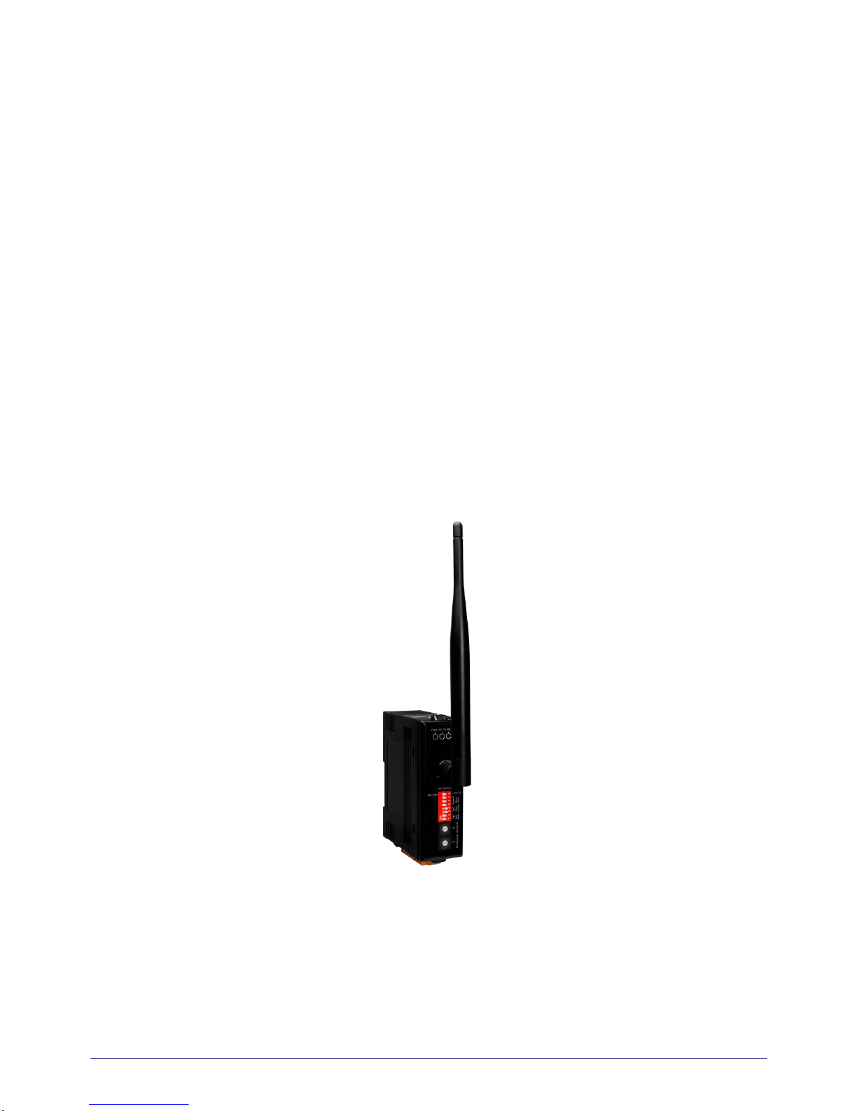
RFU-900
(RS-232/RS-485 to LoRa Radio Modem)
Page 2

RFU-900 (RS-232/RS485 to LoRa Radio Modem) User Manual Version 1.0.0 Page:2
Copyright © 2018 ICP DAS Co., Ltd. All Rights Reserved E-mail: service@icpdas.com
Table of Contents
1. Introduction ......................................................................................................................... 4
1.1. Features .......................................................................................................................... 5
1.2. Specification .................................................................................................................... 6
2. Getting Started .................................................................................................................... 7
2.1. LED Indicator .................................................................................................................. 8
2.2. Rotary Switch Setting ...................................................................................................... 8
2.3. DIP Switch Setting .......................................................................................................... 9
3. Software Utility .................................................................................................................. 10
3.1. Install the RFU-900 Utility ............................................................................................. 10
3.2. Setting up the RFU-900 ................................................................................................ 13
Appendix A. Dimensions ......................................................................................................... 18
Appendix B. Revision History ................................................................................................. 19
Page 3
RFU-900 (RS-232/RS485 to LoRa Radio Modem) User Manual Version 1.0.0 Page:3
Copyright © 2018 ICP DAS Co., Ltd. All Rights Reserved E-mail: service@icpdas.com
Important Information
Warranty
All products manufactured by ICP DAS are under warranty regarding
defective materials for a period of one year, beginning from the date of
delivery to the original purchaser.
Warning
ICP DAS assumes no liability for any damage resulting from the use of this
product.ICP DAS reserves the right to change this manual at any time
without notice. The information furnished by ICP DAS is believed to be
accurate and reliable. However, no responsibility is assumed by ICP DAS
for its use, not for any infringements o f pat ents or other rights o f t hir d par ti e s
resulting from its use.
Copyright
Copyright @ 2018 by ICP DAS Co., Ltd. All rights are reserved.
Trademark
Names are used for identification purpose only and may be registered
trademarks of their respective companies.
Contact us
If you encounter any problems while operating this device, feel free to contact us
via mail at: service@icpdas.com.
Page 4
RFU-900 (RS-232/RS485 to LoRa Radio Modem) User Manual Version 1.0.0 Page:4
Copyright © 2018 ICP DAS Co., Ltd. All Rights Reserved E-mail: service@icpdas.com
1. Introduction
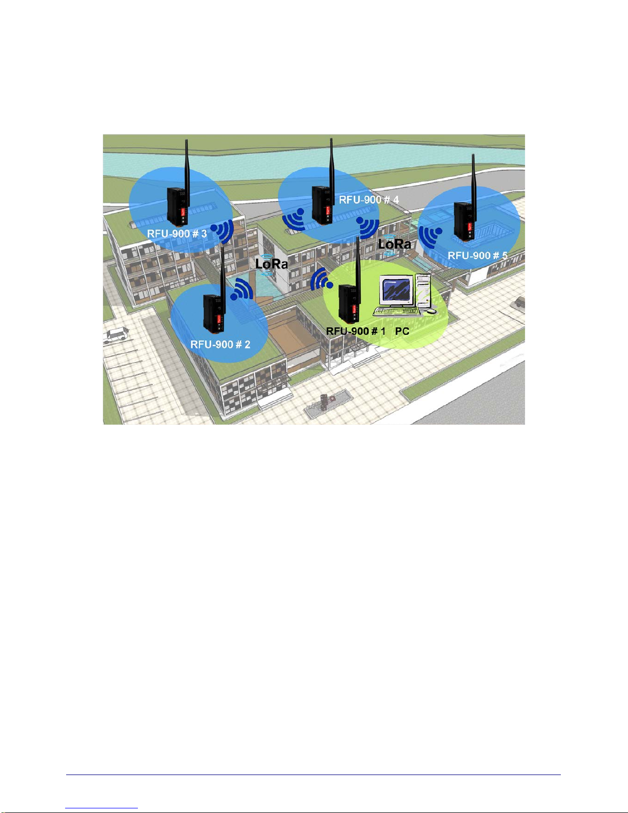
The RFU-900 is a RS-232/RS-485 to radio d evice designed for rem ot e c om mu ni cat ion operating
in a transparent way and exploiting the physical layer of LoRa (Long Range) transmission
technology.
The RFU-900 provides a maximum line of sight (LOS) transmission distance of 1000 meters (1
km) at an RF bit rate less than 1000 bps. In order to overcome the interference that may be
encountered in harsh environments, the RFU-900 allows the RF transmission bit rate to be
configure d to a minim um of 250 bps, enhancing the capability of the modem to resist noise and
other interference. Additionally, the RF channels and Group IDs are adjustable, which is helpful
to avoid interference encountered when two RFU-900 networks are adjacent. The RF channels
and the Group IDs can be configured in order to distinguish and control the different RFU-900
networks.
Page 5

RFU-900 (RS-232/RS485 to LoRa Radio Modem) User Manual Version 1.0.0 Page:5
Copyright © 2018 ICP DAS Co., Ltd. All Rights Reserved E-mail: service@icpdas.com
1.1. Features
LoRa (Long Range) transmission technology
Transparent transmiss i on mode
32 RF channels (Frequency band : 864~ 871.5MHz, 915~ 922.5MHz)
7 RF baud rates (10,000 ~ 250 bps)
Wireless line of sight (LOS) transmission range of up to 1500 meters at an RF baud rate
of 1000 bps
Provides baud bates from 1200 to 115200 bps for both the RS-232 and RS-485
interfaces
ESD Protection: Contact +/-4 kV
Is olation: 3000 VDC for DC-to-DC, 2500 Vrms using a photocoupler
DIN-Rail mountable
Operating temperature, -25 °C ~ +75 °C
Page 6
RFU-900 (RS-232/RS485 to LoRa Radio Modem) User Manual Version 1.0.0 Page:6
Copyright © 2018 ICP DAS Co., Ltd. All Rights Reserved E-mail: service@icpdas.com
1.2. Specification
RF Interface
Radio Frequency 864~ 871.5MHz, 915~ 922.5MHz
(channel: 32, recommend using 868 +/- 4 MHz)
Baud Rate 10000 ~ 250 bps
Transmission Power 15 dBm (Max.)
Antenna 2 dBi Omnidirectional Antenna
Transmission Distance up to 1500 m ( with 1000 baud, in free field conditions )
Group ID 0~255
Protocols Transparent transmit
Temporary Buffer Size 200 bytes
Configuration Dip /Rotary switch or Utility tool
COM Port Interface
RS-232 TxD, RxD and GND
RS-485 D+, DBaud Rate (bps) 1200 ~ 115200
Data Bit 5,6,7,8
Parity Bit NONE, EVEN, ODD
Stop Bit 1,2
Buffer
1024 bytes
LED Indicators
Red/ Green/ Yellow Power / RF TxD / RF RxD Status
EMS Protection
ESD +/- 4 kV Contact
EFT
+/- 1 kV
Surge +/- 1 kV
Power
Required Supply Voltage +10 VDC ~ +30 VDC
Power Consumption 1 W (Max.)
Mechanical
Dimensions (W x L x H) 108 mm x 84 mm x 33 mm ( not include antenna )
Installation DIN-Rail
Environment
Operating Temperature -25 °C ~ +75 °C
Storage Temperature -30 °C ~ +80 °C
Relative Humidity 10 ~ 90% RH, Non-condensing
Page 7

RFU-900 (RS-232/RS485 to LoRa Radio Modem) User Manual Version 1.0.0 Page:7
Copyright © 2018 ICP DAS Co., Ltd. All Rights Reserved E-mail: service@icpdas.com
2. Getting Started
Appearance
Pin Assignment
Pin Description
+Vs +10 ~ +30 V
DC
GND Power Ground
D+ RS-485 Logic High
D- RS-485 Logic Low
F.G. Frame Ground
GND RS-232 Ground
TxD RS-232 Transmit Data Pin
RxD RS-232 Received Data Pin
Antenna
Device ID
Removeable Terminal Block
Page 8
RFU-900 (RS-232/RS485 to LoRa Radio Modem) User Manual Version 1.0.0 Page:8
Copyright © 2018 ICP DAS Co., Ltd. All Rights Reserved E-mail: service@icpdas.com
2.1. LED Indicator
LED Behavior Description
PWR
On +10 ~ +30 V
DC Power On
Off Power Off
RF_Tx
On RF is transmitting data
Off R F is no data to t ransmit
RF_Rx
On RF is receiving data
Off R F is no data to receive
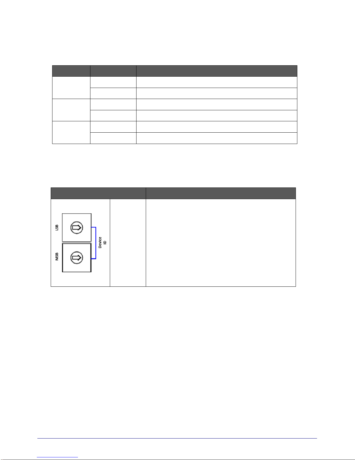
2.2. Rotary Switch Setting
Switch Name Description
Device
ID
Device ID, 0x01 ~ 0xFE
NOTE:
Each module’s “Device ID”
must be
different from each other.
0x00 and
0xFF are reserved for
broadcast id used.
Page 9

RFU-900 (RS-232/RS485 to LoRa Radio Modem) User Manual Version 1.0.0 Page:9
Copyright © 2018 ICP DAS Co., Ltd. All Rights Reserved E-mail: service@icpdas.com
2.3. DIP Switch Setting
Pin Switch Name
Description
■
: ON
□
: OFF
1 ~ 3
COM0 Baud
Rate (bps)
Baud Rate 1 2 3
115200
□ □ □
57600
■ □ □
38400
□ ■ □
19200
■ ■ □
9600
□ □ ■
4800
■ □ ■
2400
□ ■ ■
1200
■ ■ ■
4 ~ 5
COM0 Data
Bit
Data Bit 4 5
8
□ □
7
■ □
6
□ ■
5
■
■
6 ~ 7
COM0 Parity
Bit
Parity Bit 6 7
NONE
□ □
EVEN
■ □
ODD
□ ■
Reserved
■ ■
8
COM0 Stop
Bit
Parity Bit 8
1
□
2
■
Init / Run Mode
Init Mode:
Be
able to use Utility to
configure via the RS-232
interface.
Run Mode:
Use to transmit data to the RF
side via COM 0 interface.
Page 10

RFU-900 (RS-232/RS485 to LoRa Radio Modem) User Manual Version 1.0.0 Page:10
Copyright © 2018 ICP DAS Co., Ltd. All Rights Reserved E-mail: service@icpdas.com
3. Software Utility
When user s want to change the “Group ID”, “LoRa frequency”, “Module operation mode” of the
RFU-900, the RFU-900 Utility tool may be needed.
3.1. Install the RFU-900 Utility
Step 1: Get the RFU-900 Utility
The software is located at:
Usbcd:\napdos\rf_modem\utility\rfu-900\
http://ftp.icpdas.com/pub/cd/usbcd/napdos/rf_modem/utility/rfu-900/
Step 2: Install .NET Framework 3.5 component
The RFU-900 Utility tool requires the “.NET Framework 3.5 components”. If your PC’s
environment does not has “.NET Framework 3.5 components”, it will start to install .NET
Framework 3.5 components from the web site, after ex ecut ing the “Setup.exe” file.
Page 11

RFU-900 (RS-232/RS485 to LoRa Radio Modem) User Manual Version 1.0.0 Page:11
Copyright © 2018 ICP DAS Co., Ltd. All Rights Reserved E-mail: service@icpdas.com
Step 3: Install Utility tool
After installing the .Net Framework components, the software will continue to install the
Utility tool.
1. Click the “Next” button to continue.
2. Select the installation path of the RFU-900 Utility and click the “Next” button.
Page 12

RFU-900 (RS-232/RS485 to LoRa Radio Modem) User Manual Version 1.0.0 Page:12
Copyright © 2018 ICP DAS Co., Ltd. All Rights Reserved E-mail: service@icpdas.com
3. Confirm the installation. Click the “Next” button to start the installation
4. Installation complete. Click the “Close” button to exit
Page 13

RFU-900 (RS-232/RS485 to LoRa Radio Modem) User Manual Version 1.0.0 Page:13
Copyright © 2018 ICP DAS Co., Ltd. All Rights Reserved E-mail: service@icpdas.com
3.2. Setting up the RFU-900
After installing the utility tool, please follow the following steps to set up the
communication between the Utility and the RFU-900.
Step 1: Connect the PC available COM port with the RS-232 por t of the RFU-900
device via CA-0910 cable. Users can find the communication cable
(CA-0910) in the product box.
Step 2: Set the RFU-900 ‘Init.’ dip switch to ‘On’ position and reboot the module.
After rebooting, the module’s RF_Tx and RF_Rx led will flash ON/OFF per
second.
Page 14

RFU-900 (RS-232/RS485 to LoRa Radio Modem) User Manual Version 1.0.0 Page:14
Copyright © 2018 ICP DAS Co., Ltd. All Rights Reserved E-mail: service@icpdas.com
Step 3: Execute the RFU-900 Utility tool.
Step 4: Select the necessary PC’s COM Port which connected with the RFU-900
module. And then p ress the ‘Open’ button to connect with module.
Step 5: After successfully connected with the module, all device parameters will
be shown as below picture.
Page 15

RFU-900 (RS-232/RS485 to LoRa Radio Modem) User Manual Version 1.0.0 Page:15
Copyright © 2018 ICP DAS Co., Ltd. All Rights Reserved E-mail: service@icpdas.com
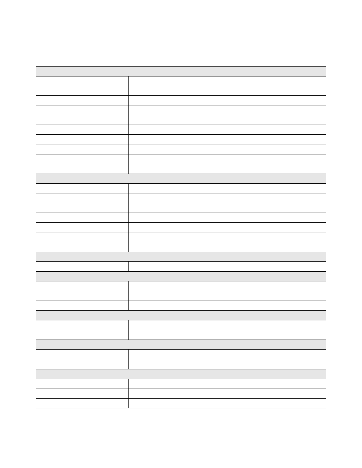
Step 6: The detail information about module’s parameters are listed in below
table.
Item
Name
Description
1
Firmware Version
RFU-900 firmware version
2
Device ID
Device ID, valid range: 0x01 ~ 0xFE.
Set by using rotary switch
Device ID Description
1 ~ 254
(0x01 ~ 0xFE)
Each RFU-900’s “Device ID” must
be different from each other in the
same RF frequency.
0x00 and
0xFF
0x00 and 0xFF are reserved for
broadcast id used, don’
t set these
two values.
3
Group ID
Group ID, valid range: 0 ~ 255 (0x00 ~ 0xFF).
Group ID Description
1 2 3
4
5 6 7
8
9
Page 16

RFU-900 (RS-232/RS485 to LoRa Radio Modem) User Manual Version 1.0.0 Page:16
Copyright © 2018 ICP DAS Co., Ltd. All Rights Reserved E-mail: service@icpdas.com
0 ~ 254
(0x00 ~ 0 xFE)
The module has same group id
(0x00 ~
0xFE) setting can
communicate with each other
255
(0xFF)
The module has the group id (0xFF)
setting can communicate with other
module which group id setting is
0x00 to 0xFF
4
Module Mode
End-device or repeater mode
Mode Description
End-device Message can be transmitted
between UART (COM0) and RF
side
When receiving a valid LoRa
signal, data will be transmitted to
the UART (COM0) side.
Repeater The UART (COM0) function will be
disabled.
When receiving a valid LoRa
signal, data will be re-transmitted
to the RF side
5
COM 0 Setting
Baud Rate:
8 UART baud rates (115200, 57600, 38400, 19200,
9600, 4800, 2400, 1200 bps)
Data Bit:
4 UART data bit (5,6,7,8)
Parity Bit:
3 UART parity bit (NONE, EVEN, ODD)
Stop Bit:
2 UART stop bit (1,2)
6
LoRa Frequency
32 RF frequencies (864, 864.5, 865, 865.5, 866,
866.5, 867, 867.5,
868, 868.5, 869, 869.5, 870,
870.5, 871, 871.5, 915, 915.5, 916, 916.5, 917,
Page 17

RFU-900 (RS-232/RS485 to LoRa Radio Modem) User Manual Version 1.0.0 Page:17
Copyright © 2018 ICP DAS Co., Ltd. All Rights Reserved E-mail: service@icpdas.com
917.5, 918, 918.5, 919, 919.5,
920, 920.5, 921,
921.5, 922, 922.5 MHz)
7
LoRa Bit Rate
7 RF bit rates (10000, 60
00, 3400, 1800, 1000,
500, 250 bps)
The maximum supported RF receive sensitivities
of each baud rate are listed below.
Baud rate (bps)
Max. RF Receive
Sensitivity (dBm)
10000 -120.0
6000 -123.0
3400 -126.0
1800 -129.0
1000 -131.5
500 -134.0
250 -137.0
8
RSSI information
Enable or disable the COM0 port to add “RSSI
(Received Signal Strength Indicator, positive
number)” and “SNR (Signal-to-noise ratio, 2's
complement)”, 2 bytes RF signal information, at the
beginning of the received LoRa data when
receiving a valid LoRa message.
SNR RSSI
SNR byte >= 0 RSSI = -157 + (16/15 * RSSI byte)
SNR byte < 0
RSSI = -157 + (RSSI byte + SNR
byte * 0.25)
9
RF Output power
Value 0(0) ~ F(15) are mapping to the RF output
power range of 0 ~ 15 dBm.
Step 7: Press the save button to save all device parameters into module
Step 8: After se tting, switch the RFU-900 “Init.” switch to “Off” position and reboot
the module.
Page 18
RFU-900 (RS-232/RS485 to LoRa Radio Modem) User Manual Version 1.0.0 Page:18
Copyright © 2018 ICP DAS Co., Ltd. All Rights Reserved E-mail: service@icpdas.com
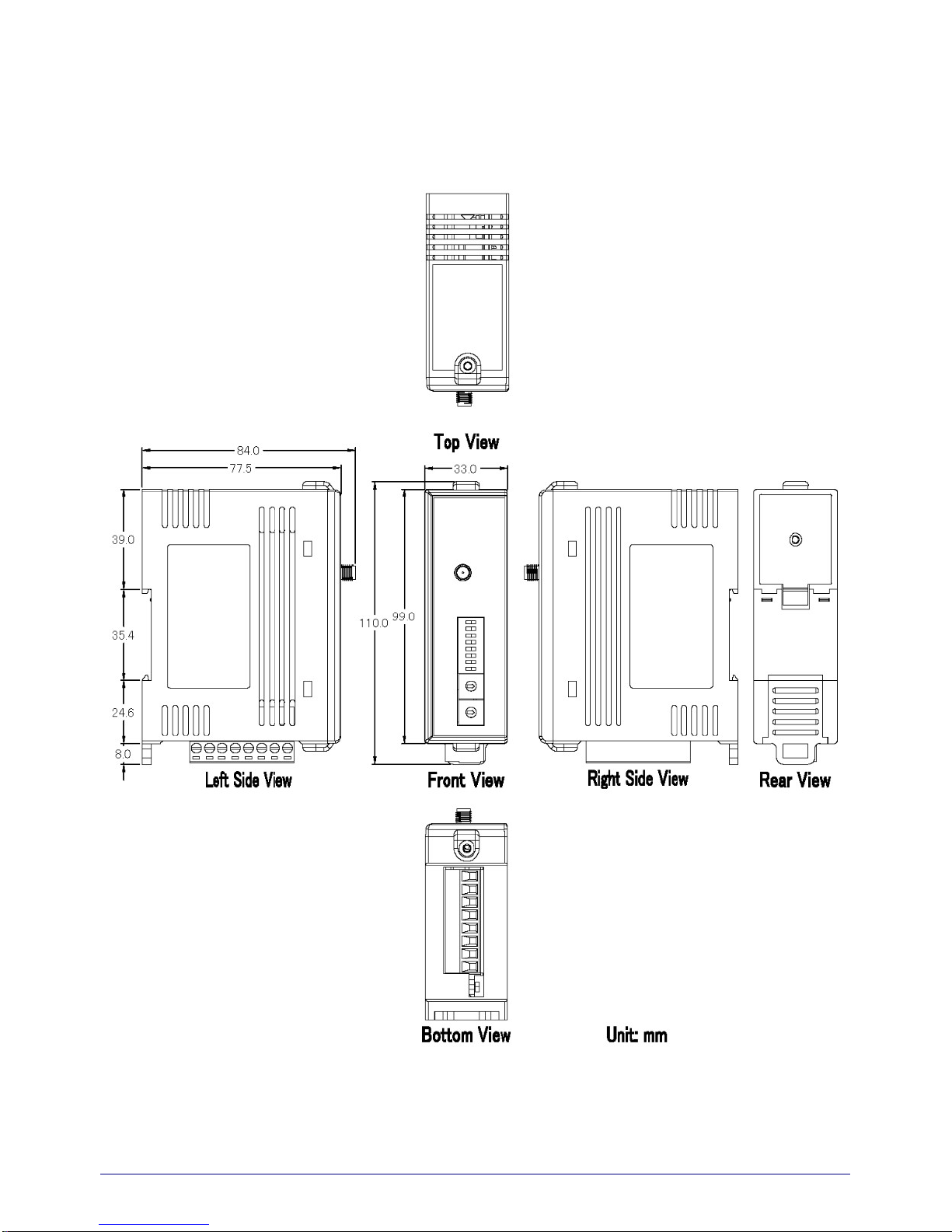
Appendix A. Dimensions
Page 19

RFU-900 (RS-232/RS485 to LoRa Radio Modem) User Manual Version 1.0.0 Page:19
Copyright © 2018 ICP DAS Co., Ltd. All Rights Reserved E-mail: service@icpdas.com
Appendix B. Revision History
This chapter provides revision history information to this document.
The table below shows the revision history.
Revision Date Description
1.0.0 Jan. 2018 Initial issue
 Loading...