

Page 1
Installation
Instructions
For
R410-A
Refrigerant
SPLIT SYSTEM
Premium Line
AC CONDENSERS
Save This Manual for Future Reference
421 01 3204 03
Dec. 2004
Page 2
I Installation Instructions R410-A Split System Condensers I
Installation/Startup Information
These instructions must be read and understood com-
pletely before attempting installation.
Installation or repairs made by unqualified
persons can result in hazards to you and others.
Installation MUST conform with local building
codes or, in the absence of local codes, with the
the National Electrical Code NFPA 70/ANSI
C1-1999 or current edition and Canadian
Electrical Code Part 1 CSA C.22.1.
The information contained in this manual is
intended for use by a qualified service technician
familiar with safety procedures and equipped
with the proper tools and test instruments.
Failure to carefully read and follow all instruc-
tions in this manual can result in equipment
malfunction, property damage, personal injury
and/or death.
After uncrating unit, inspect thoroughly for hidden damage.
If damage is found, notify the transportation company im-
mediately and file a concealed damage claim.
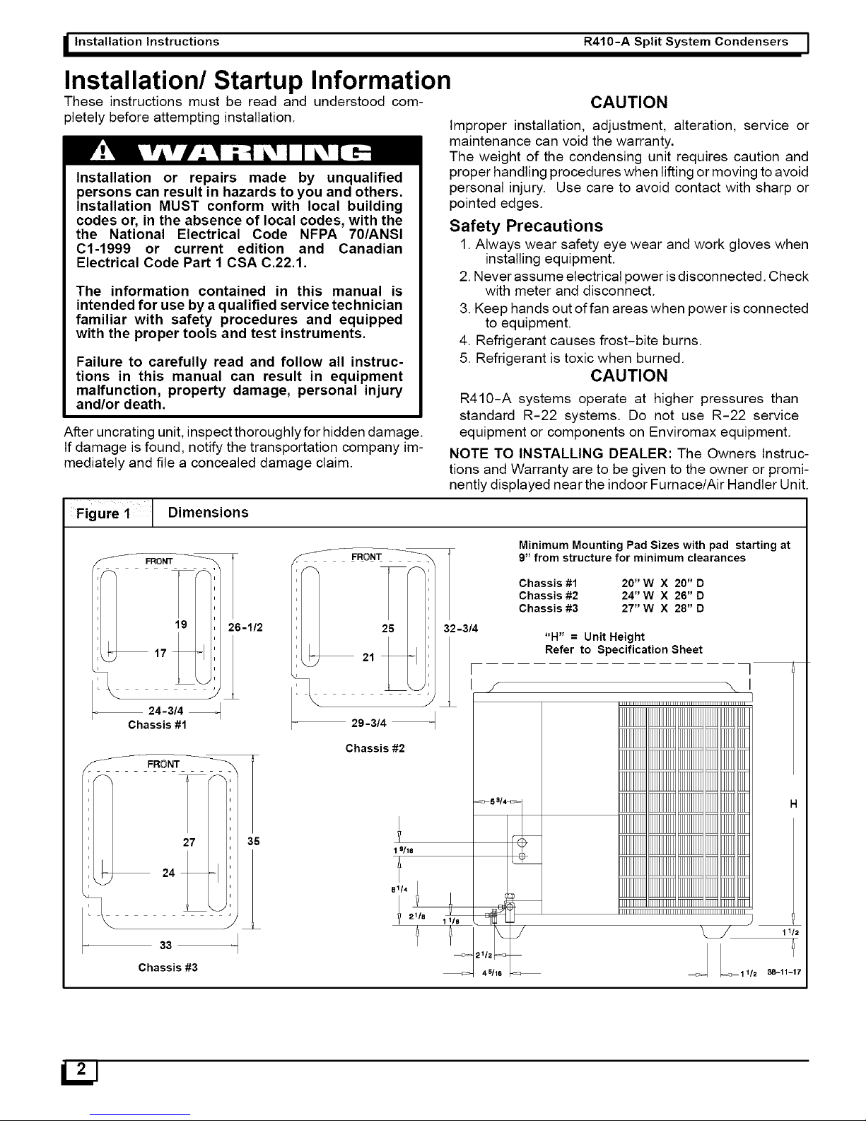
Figure 1 1 Dimensions
-- 24-3/4
Chassis #1
6-1/2
FRONT
36
33
Chassis #3
CAUTION
Improper installation, adjustment, alteration, service or
maintenance can void the warranty.
The weight of the condensing unit requires caution and
proper handling procedures when lifting or moving to avoid
personal injury. Use care to avoid contact with sharp or
pointed edges.
Safety Precautions
1. Always wear safety eye wear and work gloves when
installing equipment.
2. Never assume electrical power isdisconnected. Check
with meter and disconnect.
3. Keep hands out of fan areas when power is connected
to equipment.
4. Refrigerant causes frost-bite burns.
5. Refrigerant is toxic when burned.
CAUTION
R410-A systems operate at higher pressures than
standard R-22 systems. Do not use R-22 service
equipment or components on Enviromax equipment.
NOTE TO INSTALLING DEALER: The Owners Instruc-
tions and Warranty are to be given to the owner or promi-
nently displayed near the indoor Furnace/Air Handler Unit.
FRONT
26 '
29-3/4 _
Chassis #2
T
32-3/4
Minimum Mounting Pad Sizes with pad starting at
9" from structure for minimum clearances
Chassis #1 20" W X 20" D
Chassis #2 24" W X 26" D
Chassis #3 27" W X 28" D
f
"H" = Unit Height
Refer to Specification Sheet
]
I
IIIIIIIIIIIIIIIIIIIIIIIIIIIIII
IIIIIIIIII IIIIIIIIII IIIIIIIIII q_T T_ ]q_
11/2
L1 1/2 38-11-17
Page 3
I Split System Condensers R410-A Installation Instructions I
Locating The Outdoor Unit:
Check local codes covering zoning, noise, platforms.
If practical, avoid locating next to fresh air intakes, vent or
bedroom windows. Noise may carry into the openings and
disturb people inside.
Placement of the unit should be in a well drained area or
unit must be supported high enough so runoffwill not enter
the unit.
Do not locate where heat, lint or exhaust fumes will be dis-
charged on unit (as from dryer vents).
Clearances:
Rooftop installations are acceptable providing the roof will
support the unit and provisions are made for water drain-
age and the noise or vibration through the structure.
NOTE: Roof mounted units exposed to winds above 5
mph may require wind baffles. Consult the factory for
additional information.
Do not install the unit ina recessed or confined area where
recirculation of discharge air may occur.
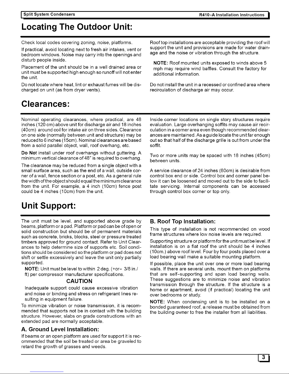
Nominal operating clearances, where practical, are 48
inches (120 cm) above unit for discharge air and 18 inches
(40cm) around coil for intake air on three sides. Clearance
on one side (normally between unit and structure) may be
reduced to 6inches (15cm). Nominal clearances are based
from a solid parallel object, wall, roof overhang, etc.
Do Not install under roof overhangs without guttering. A
minimum vertical clearance of 48" is required to overhang.
The clearance may be reduced from a single object with a
small surface area, such as the end of a wall, outside cor-
ner of a wall, fence section or a post, etc. As a general rule
the width ofthe object should equal the minimum clearance
from the unit. For example, a 4 inch (10cm) fence post
could be 4 inches (10cm) from the unit.
Unit Support:
Inside corner locations on single story structures require
evaluation. Large overhanging soffits may cause air recir-
culation in a corner area even though recommended clear-
ances are maintained. As a guide locate the unit far enough
out so that half of the discharge grille is out from under the
soffit.
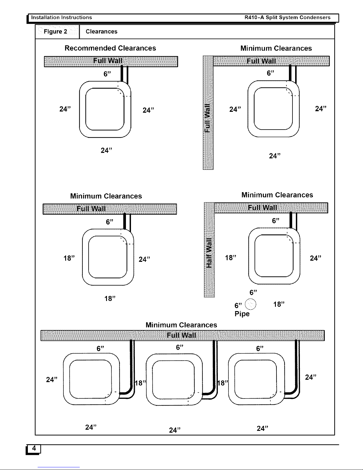
Two or more units may be spaced with 18 inches (45cm)
between units.
A service clearance of 24 inches (60cm) is desirable from
control box end or side. Control box and corner panel be-
low it can be loosened and moved out to the side to facili-
tate servicing. Internal components can be accessed
through control box corner or top only.
The unit must be level, and supported above grade by
beams, platform ora pad. Platform or pad can be of open or
solid construction but should be of permanent materials
such as concrete, bricks, blocks, steel or pressure treated
timbers approved for ground contact. Refer to Unit Clear-
ances to help determine size of supports etc. Soil condi-
tions should be considered so the platform or pad does not
shift or settle excessively and leave the unit only partially
supported.
NOTE: Unit must be level to within 2 deg. (+or- 3/8 in./
ft) per compressor manufacturer specifications.
CAUTION
Inadequate support could cause excessive vibration
and noise or binding and stress on refrigerant lines re-
suiting in equipment failure.
To minimize vibration or noise transmission, it is recom-
mended that supports not be in contact with the building
structure. However, slabs on grade constructions with an
extended pad are normally acceptable.
A. Ground Level Installation:
If beams or an open platform are used for support it is rec-
ommended that the soil be treated or area be graveled to
retard the growth of grasses and weeds.
B. Roof Top Installation:
This type of installation is not recommended on wood
frame structures where low noise levels are required.
Supporting structure or platform for the unit must be level. If
installation is on a flat roof the unit should be 4 inches
(10cm.) above roof level. Four by four posts placed over a
load bearing wall make a suitable mounting platform.
If possible, place the unit over one or more load bearing
walls. If there are several units, mount them on platforms
that are self-supporting and span load bearing walls.
These suggestions are to minimize noise and vibration
transmission through the structure. If the structure is a
home or apartment, avoid (if practical) locating the unit
over bedrooms or study.
NOTE: When condensing unit is to be installed on a
bonded guaranteed roof, a release must be obtained from
the building owner to free the installer from all liabilities.
3LjJ
Page 4
I Installation Instructions
Figuro2 C,oarancos
Recommended Clearances
R410-A Split System Condensers I
Minimum Clearances
24 _
24 _
24 _
24 _
Minimum Clearances
Minimum Clearances
18 _
Minimum Clearances
18 _
24 _
24 _
24 _
_J
Page 5

I Split System Condensers R410-A Installation Instructions I
Installing Refrigerant Lines
Component Matches
Check to see that you have the proper system compo-
nents. ONLY R410-A APPROVED MATCHED SYSTEM
COMPONENTS MAY BE USED. Refer to the Split Sys-
tem Summary or www.ariprimenet.org for match data
and orifice sizes.
The outdoor units are shipped with a refrigerant charge to
match the indoor unit and 25 ft. (7.5m) of refrigerant line. If
shorter or longer lines are used, the charge will have to be
adjusted.
TOTAL LENGTH OF REFRIGERANT LINES MUST NOT
EXCEED 75 ft. WITH A MAXIMUM VERTICAL SEPARA-
TION OF 50 ft. BETWEEN THE OUTDOOR AND IN-
DOOR UNITS WITH 2 TRAPS,
NOTE: A crankcase heater must be used when refriger-
ant lines exceed 50 ft.
REFRIGERANT TUBING AND FLOW CONTROL (Fig. 3)
Field-supplied tubing must be of refrigerant grade. Suction tube
must be insulated. Do not use damaged, dirty, or contaminated
tubing because it may plug refrigerant flow-control device. AL-
WAYS evacuate the coil and field-supplied tubing to 500 microns
before opening outdoor unit service valves.
CAUTION: Braze with SiI-Fos or Phos-copper on copper to
copper joints and wrap a wet cloth around rear of fitting to
prevent damage to TXV.
Figure 3 I Refrigerant Flow-Control Device
Refrigeration Line Sets
Ifit is necessary toadd tubing inthe field, use dehydrated or
dry sealed deoxidized copper refrigeration tube. DO NOT
use copper water pipe.
CAUTION
If ANY refrigerant tubing is buried, provide a 6 in. verti-
cal rise at service valve. Refrigerant tubing lengths up
to 36 in. may be buried without further special consider-
ation. For lengths above 36 in., contact the factory.
It is important that notubing is cut or seals broken until
you are ready to actually make connections to the
evaporator and to the condenser section.
Do not remove rubber plugs or copper caps from the
tube ends until ready to make connections at evapora-
tor and condenser.
CAUTION
Do not leave system open to atmosphere any longer
than minimum required for installation. POE oil in com-
pressor is extremely susceptible to moisture absorp-
tion. Always keep ends of tubing sealed during
installation.
Be extra careful with sharp bends. This tubing can "kink"
very easily, and if this occurs, the entire tube length will
have to be replaced. Extra care at this time will eliminate
future service problems.
Suspension And Installation Of
Refrigeration Lines
DO NOT fasten liquid or suction lines indirect contact with
the floor or ceiling joist. Use an insulated or suspension
type of hanger. Keep both lines separate, and insulate the
suction line. Both lines should be insulated in long runs in
an attic or underground in a raceway.
Do not let refrigerant lines come in direct contact with
foundation. When running refrigerant lines through the
foundation or wall, the openings should be made large
enough to allow for a sound absorbing material to be
placed or installed between the tubing and the foundation.
This will prevent noise transmission between the tubing
and the wall section (foundation) or the building.
Installation Instructions For Condensing
Units That Are Higher Than Evaporator
It is recommended that vertical suction risers not be up-
sized. Proper oil return to the compressor should be main-
tained with suction gas velocity. If velocities drop below
1500 fpm (feet per minute), oil return will be decreased. An
oil trap should be installed every 20' of vertical suction line
riser (condenser above evaporator.) Refer to line sizing
charts.
Page 6

I Installation Instructions R410-A Split System Condensers I
Figure 4 I Oil Traps
10" Max
Min.
Line Valves
The outdoor condensing unit issupplied with straight sweat
brass service valves with copper stubs.
All line valves are positioned to seal the refrigerant in the
condensing unit with gauge ports open to connecting lines
when the schraeder valve is depressed. Gauge ports have
schraeders installed and require use of charging hoses
with depressors.
Brazing Connections
Fire Hazard
Refrigerant and oil mixture under pressure could
ignite as it escapes and contacts brazing torch
resulting in Fire. Make sure the refrigerant charge
is properly removed from both the high and low
sides of the system before brazing any compo-
nent or lines.
FAILURE TO DO SO COULD RESULT IN BODILY
INJURY OR DEATH.
Before making braze connections, be sure all joints are
clean. Before heat is applied for brazing, nitrogen should
be flowing through the tubing to prevent oxidation and
scale formation on the inside of the tubing.
Liquid & Suction Lines
Fully annealed refrigeration lines should be used when
installing the system.
The following is the recommended method for making
braze connections at the refrigerant line connections:
1. Clean refrigerant tube end with emery cloth or steel
brush.
2. Use a suitable brazing alloy for copper to copper joints.
3. Insert tubing into swage fitting connection.
4. Apply heat absorbing paste or heat sink product to pre-
vent damage to the service valve.
CAUTION
Do not heat valve body above 250 degrees F.
5. Braze joint.
6. Quench the joint and tubing with water using a wet rag.
Leave rag on fitting body and re-wet with water to help cool
area.
Evacuating Refrigerant Lines and Coil
NOTE
Intentional release of CFC, HFC or HCFC Refrigerants
to the Atmosphere violates Federal Law. It may also
violate State and Local Codes. Check all Federal, State
and Local Codes before proceeding.
These instructions are intended for use with condensing
units that are precharged at the factory with adequate re-
frigerant to handle 25 feet.
NOTE: Do not use any portion of the charge for purging or
leak testing. It is mandatory that a thorough evacuation of
the refrigerant in the piping and evaporator be performed.
The liquid line and suction line service valves have been
closed after final testing at the factory. Do not disturb
these valves until the lines have been leak checked
and evacuated or the charge in the unit may be lost.
CAUTION
Never use the system compressor as a vacuum pump.
Refrigerant lines and indoor coil should be evacuated us-
ing the recommended deep vacuum method of 500 mi-
crons. The alternate triple evacuation method may be used
if the procedure outlined below is followed. Always break a
vacuum with dry nitrogen.
Deep Vacuum Method
The deep vacuum method requires a vacuum pump capa-
ble of pulling a vacuum of 500 microns and a vacuum gage
capable of accurately measuring this vacuum depth. The
deep vacuum method is the most positive way of assuring
a system is free of air and liquid water.
Figure 5
5000
4500
4000
3500
3000
2500
o
2000
1500
1000
50O
Deep Vacuum Graph
LEAKIN
SYSTEM
VACUUM TIGHT
TOO WET
TIGHT
DRY SYSTEM
0 1 23 4 5 67
MINUTES
Page 7

I Split System Condensers R410-A Installation Instructions I
Triple Evacuation Method
The triple evacuation method should only be used when
vacuum pump is only capable of pumping down to 28 in. of
mercury vacuum and system does not contain any liquid
water. Refer to Fig. 8 and proceed is as follows:
1. Pump system down to 28 in. of mercury and allow
pump to continue operating for an additional 15 min-
utes.
2. Close service valves and shut off vacuum pump.
3. Connect a nitrogen cylinder and regulator to system
and open until system pressure is 2 psig.
4. Close service valve and allow system to stand for 1hr.
During this time, dry nitrogen will be able to diffuse
throughout the system absorbing moisture.
5. Repeat this procedure as indicated in Fig. 6. System
will then be free of any contaminants and water va-
por.
The service valve cap is a primary seal for the valve and
must be properly tightened to prevent leaks. Make sure cap
is clean and apply refrigerant oil to threads and sealing sur-
face of cap.
For valves with retaining rings: Replace service valve
cap and torque to; 8-11 ft. Ibs. on 1/4" and 3/8" valves,
12-16 ft. Ibs. on 5/8" and 3/4", 15-21 ft. Ibs on 7/8" valves. If
torque wrench is not available, tighten cap finger tight and
then tighten one (1) additional wrench flat or 1/6 of a turn.
For valves with rolled tops: Replace service valve cap
tighten cap finger tight and then tighten one (1) additional
wrench fiat or 1/6 of a turn to properly seat the sealing sur-
faces. Subsequent installations will seat with 1/2 to 1
wrench flat of turning.
Gauge Ports: All Valves
Check for leaks at the schrader port and tighten valve core
if necessary. Install plastic caps finger tight.
gure 6[
Fi Triple Evacuation Chart
IEVACUATEI
IBREAK VACUUM WITH DRY NITROGEN
IEVACUATE I
IBREAK VACUUM WITH DRY NITROGEN
IEVACUATE I
CHECK FOR TIGHT, DRY SYSTEM
(IF IT HOLDS DEEP VACUUM)
I CHARGE SYSTEM J
Valve Actuation: Service Valves
Remove the service valve cap, if there is a male valve stem
see instructions for Ball Valves. For the standard service
valve there are two variations, but both have internal
stems. The first style uses an internal snap ring to retain the
valve stem and the second has a rolled top and also has
finer threads on the valve cap. NOTE: You may encounter
more than one type of valve on a unit.
For service valves fully insert a hex wrench into the stem. A
back-up wrench is required on the valve body to open the
valve stem. Backout counterclockwise until the valve stem
stops or just touches the retaining ring. NOTE: THIS IS
NOT A BACKSEATING VALVE. For valves with retainer
rings care must be taken to prevent dislodging them when
opening valve.
Ball Valves
On models with ball type valves use a 6" crescent wrench
to rotate the valve stem 90° counter clockwise. Retighten
valve cap to 6-8 ft. Ibs. If torque wrench is not available,
tighten cap finger tight and then tighten one (1/2) additional
wrench fiat.
REFRIGERATION PIPING & CHARGING
The recommended method of addition or removal of refrig-
erant is by weight.
Some matching coils may need more refrigerant than the
factory charge. If you can't determine charge by weight,
then check charge by superheat method and performance
curves. The oil charge is sufficient for 50 feet.
For oil requirements refer to Figure 7. For piping lengths
up to 75 feet refer to Figure 8 for pipe size, and Figure 9 for
refrigerant adjustment.
On applications where liquid fioodback to the compressor
is likely to occur, use of a crankcase heater is recom-
mended.
Figure 7 - Addition of Refrigeration Oil
Distance
(Feet)
0-50
51
6O
75
Suction Line Size
5/8, 3/4, 7/8 1- 1/8
1 oz. 2 oz.
2 oz. 4 oz.
3 oz. 6 oz.
Figure 8 - LINE SIZING
Model Series
All Series
All Series
Size-ton Liquid Suction
1 1/2 to 3 3/8" 3/4"
3 1/2 to 5 3/8" 7/8"
Figure 9 Addition of Refrigeration Charge
Liquid Line Diameter oz. Per Linear Ft. *
3/8 .60
1/2 1.20
Page 8

I Installation Instructions R410-A Split System Condensers I
Electrical Wiring
A/C Control Box
Electrical Shock Hazard.
Shut off electric power at fuse box or service pan-
el before making any electrical connections.
Failure to shut off electric power can result in,
property damage, personal injury and/or death.
The supply voltage should be 208-230 volts (196 volt mini-
mum to 253 volts maximum) 60Hz single phase.
APPROVED FOR USE WITH COPPER CONDUCTORS
ONLY. DO NOT USE ALUMINUM WIRE.
REFER TO UNIT RATING PLATE FOR CIRCUIT
PROTECTION.
ALL Low Voltage
Connections MUST be
made in this AREA
Contactor
Low Voltage
Entrance
Ground Lug
Line Voltage
Entrance
Grounding
Permanently ground unit in accordance with the National
Electrical Code and local codes or ordinances. Use a cop-
per conductor of the correct size from the grounding termi-
nal in control box to a grounded connection in the service
panel ora properly driven and electrically grounded ground
rod.
Wiring Connections
Make all outdoor electrical supply (Line Voltage) connec-
tions with raintight conduit and fittings. Most codes require
a disconnect switch outdoors within sight of the unit.
Route Line Voltage wiring through entrance and through
hole in the bottom of the Control Box to connect to Contac-
tor and Ground Lug.
Route Low Voltage wiring through entrance ONLY and
make ALL low voltage connections to the low voltage pig-
tails in the area below the Control Box. (Two Yellow wires,
AC or W,Y,O,BL). The pigtail wires have 600V insulation
meeting approval for use in high voltage areas.
See Figures 10 thru 11 and Wiring Diagram on unit.
Use of Rigid Metal Conduit
It is recommended that wires be tied together or twisted to-
gether inside the conduit. This will minimize any buzzing
type sounds that could be produced with high current
loads, such as during starting. Under some conditions it
may be necessary to use a hard start kit to eliminate prob-
lem noises.
Control Box Access
Remove the four screws. Cover is notched so it will slide
out from under top edge of unit.
Figure 1 [ A/C Condenser Typical Low
! Voltage Connections
Indoor
Thermostat
( x2
R G
I I
(Compressor q
(Co
BL W
I J
Outdoor
Unit
ontactor)
Y--
nmon 24V)
A y _
INDOOR
GAS
BLOWER OR FURNACE
COIL
Start-Up Procedure
Start-up Procedure - Cooling Operation
1. Close electrical disconnects to energize system.
IJJ
.
Energize crankcase heater on units so equipped for
24Hrs, then proceed with Start UP.
Page 9

I Split System Condensers R410-A Installation Instructions I
3. Set Thermostat selector switch to OFF.
4. Set room thermostat at desired temperature. Be
sure setpoint is below indoor ambient temperature
for cooling and above indoor ambient for heating.
5. Set the system switch of the thermostat on COOL
and fan switch for continuous operation or AUTO, as
desired. Operate unit for 15-20 minutes, then check
the system refrigerant charge if it was necessary to
adjust.
6. After the refrigerant charge has been adjusted, the
system is now ready for continuous operation.
Final Refrigeration Charge Adjustment
Before any adjustment is made to the refrigerant charge, it
is imperative that the air flow characteristics of the indoor
blower be established.
When checking indoor air flow, it is important to remember
that the blower will deliver a higher quantity of air across a
dry coil versus a wet coil. Blower charts are calculated with
a dry coil.
Recommended air flow for installations of cooling units is
350-450 CFM per ton (12,000 BTUH) through a wet coil.
Refer to indoor unit installation instructions for proper
methods of determining air flow and blower perfor-
mance.
Factory charge is shown on unit information plate. R-410A
refrigerant cylinders contain a dip tube which allows liquid
refrigerant to flow from cylinder in upright position. Charge
R410-A units with cylinder in upright position and a com-
mercial-type metering device in manifold hose. Charge re-
frigerant into suction line.
NOTE: If superheat or subcooling charging conditions
are not favorable, charge must be weighed in accor-
dance with unit rating plate 0.5 oz/ft of 3/8-in. liquid line
above or below 25 ft respectively.
To Check System Refrigerant Charge
(Superheat Method), Cooling Only
NOTE: On units with two speed fan control the fan will be
on low speed if the temperature is below 83° E Pull one of
the yellow low voltage wires offthe fan control and the unit
will default to high speed fan for servicing. Reconnect wire
after checking.
Units with Cooling Mode TXV
Units installed with cooling mode TXV require charging by
the subcooling method.
1. Operate unit a minimum of 10 minutes before check-
ing charge.
2. Measure liquid service valve pressure by attaching
an accurate gage to service port.
3. Measure liquid line temperature by attaching an ac-
curate thermistor type or electronic thermometer to
liquid line near outdoor coil.
4. Refer to unit rating plate for required subcooling tem-
perature.
5. Refer to Figure 12. Find the point where required
subcooling temperature intersects measured liquid
service valve pressure.
6. To obtain required subcooling temperature at a spe-
cific liquid line pressure, add refrigerant if liquid line
temperature is higher than indicated or reclaim refrig-
erant if temperature is lower. Allow a tolerance of 3E
Page 10

I Installation Instructions R410-A Split System Condensers I
Figure 12
Required Liquid-Line Temperature (°F)
LIQUID
PRESSUREAT
SERVICEVALVE
(PSIG)
LIQUID
PRESSUREAT
REQUIREDSUBCOOLING
TEMPERATURE
(°F) SERVICEVALVE
8 1o 12 I 14 16 18 (PSIG)
58 56 54 52 50 48 326
60 58 56 54 52 50 335
62 60 58 56 54 52 345
64 62 60 58 56 54 354
66 64 62 60 58 56 364
68 66 64 62 60 58 374
70 68 66 64 62 60 384
72 70 68 66 64 62 395
74 72 70 68 66 64 406
76 74 72 70 68 66 416
78 76 74 72 70 68 427
80 78 76 74 72 70 439
82 80 78 76 74 72 450
84 82 80 78 76 74 462
86 84 82 80 78 76 474
88 86 84 82 80 78 486
90 88 86 84 82 80 499
92 90 88 86 84 82 511
REQUIREDSUBCOOLING
TEMPERATURE
(°F)
8 I 10 12
189 94 92 90
195 96 94 92
202 98 96 94
208 100 98 96
215 102 100 98 96
222 104 102 100 98
229 106 104 102 100
236 108 106 104 102
243 110 108 106 104
251 112 110 108 106
259 114 112 110 108
266 116 114 112 110
274 118 116 114 112
283 120 118 116 114
291 122 120 118 116
299 124 122 120 118
308 126 124 122 120
317 128 126 124 122
14 I 16 18
88 86 84
90 88 86
92 90 88
94 92 90
94 92
96 94
98 96
100 98
102 100
104 102
106 104
108 106
110 108
112 110
114 112
116 114
118 116
120 118
Figure 13
Superheat Charging
OUTDOOR EVAPORATORENTERINGAIR TEMPERATURE(°FWB)
TEMP
54 56 58 60 62 64 66 68 70 72 I 74 76
(°F)
55 14 17 20 23 26 29 32 35 37 40 42 45
60 12 15 18 21 24 27 30 33 35 38 40 43
65 10 13 16 19 21 24 27 30 33 36 38 41
70 7 10 13 16 19 21 24 27 30 33 36 39
75 e 9 I 12I 15 I 18 I 21 24 28 31 34 37
80 5 I 8 I 12 I 15 I 18 21 25 28 31 35
85 8 111115 19 22 26 30 33
90 5 I 9 I 13 16 20 24 27 31
95 6 I 10 14 18 22 25 29
100 8 12 15 20 23 27
105 5 9 13 17 22 26
110 6 11 15 20 25
115 8 14 18 23
--Where a dash appears,do nota_emptb charge sys_m underhese conditionsorretigerantslugging may occur. Charge mustbe
weighedin. NOTE:Superheat°F isatlow-side service port.
llj2J
Page 11

I Split System Condensers R410-A Installation Instructions I
Figure 14
Required Suction-Line Temperature
SUPERHEAT SUCTION PRESSURE ATSERVICE PORT(PSIG)
TEMP(°F) 107.8 112.2 116.8 1212 126.0 130.8 138.8 140.8 145.8
0 35 37 39 41 43 45 47 49 51
2 37 39 41 43 45 47 49 51 53
4 39 41 43 45 47 49 51 53 55
6 41 43 45 47 49 51 53 55 57
8 43 45 47 49 51 53 55 57 59
10 45 47 49 51 53 55 57 59 61
12 47 49 51 53 55 57 59 61 63
14 49 51 53 55 57 59 61 63 65
16 51 53 55 57 59 61 63 65 67
18 53 55 57 59 61 63 65 67 69
20 55 57 59 61 63 65 67 69 71
22 57 59 61 63 65 67 69 71 73
24 59 61 63 65 67 69 71 73 75
26 61 63 65 67 69 71 73 75 77
28 63 65 67 69 71 73 75 77 79
30 65 67 69 71 73 75 77 79 81
32 67 69 71 73 75 77 79 81 83
34 69 71 73 75 77 79 81 83 85
36 71 73 75 77 79 81 83 85 87
38 73 75 77 79 81 83 85 87 89
40 75 77 79 81 83 85 87 89 91
To Check System Refrigerant Charge
(Heating Mode)
Maintenance
The recommended method of addition or removal of
charge in the heating mode is by weight. The system op-
eration may be checked against the performance charts.
Remember, indoor airflow must be approximately 400
CFM per ton to compare operation to performance charts.
In some areas, with high humidity, the temperature ter-
mination may require adjustment for complete removal of
ice from the coil. For best economy, always set to the low-
est temperature that will keep the coil clear of ice.
NOTE: The term ice means hard but not frost. During nor-
mal operation, the coils may become coated with frost until
they are solid white. The temperature for the defrost should
be set so the frost and ice melt off completely without hard
ice building up on the coil.
Electrical Shock Hazard.
Shut off electric power atfuse box or service pan-
el before making any electrical connections,
Failure to shut off electric power can result in,
property damage, personal injury and/or death.
Condensate Drain
During the cooling season check at least monthly for free
flow of drainage and clean if necessary.
Cleanliness
These tips will help you keep your air conditioner looking
better and working more efficiently:
1. Free air flow is essential. Keep the outdoor coil clean
and free of restrictions. Keep fences, shrubs, snow
drifts and any other obstructions at least two feet from
all coil air inlets.
Page 12

I Installation Instructions
2.
R410-A Split System Condensers I
Keep the coil free of grass clippings, weeds and other
debris. BE SURE TO TU RN OFF ELECTRICITY BE-
FORE CLEANING!
Coils may require cleaning. The coil should al-
ways be cold when cleaning. Use an alkaline
based cleaner only. Cleaning a hot coil or using
an acid based cleaner will remove the paint from
the fins and may clog the coil.
. Never use a weather cover over the outdoor unit un-
less itis aventilated type or made of breathable fabric
that will allow moisture to evaporate rapidly. A cover
that holds moisture in the unit will cause more rust
build-up and damage than normal exposure to
weather.
Page 13

I Split System Condensers R410-A Installation Instructions I
R410-A QUICK REFERENCE GUIDE
R-410A refrigerant operates at 50-70 percent higher pressures than R-22. Be sure that servic-
ing equipment and replacement components are designed to operate with R-410A.
R410-A refrigerant cylinders are rose colored.
R410-A refrigerant cylinders have a dip tube which allows liquid to flow out of cylinder in upright
position. Recovery cylinder service pressure rating must be 400 psig, DOT 4BA400 or DOT
BW400.
Enviromax systems should be charged with liquid refrigerant. Use a commercial type metering
device in the manifold hose. Manifold sets should be 800 psig high side and 250 psig low side with
550 psig low-side retard.
Use hoses with 800 psig service pressure rating.
Leak detectors should be designed to detect HFC refrigerant. R410-A, as with other HFCs, is
only compatible with POE oils. Vacuum pumps will not remove moisture from oil.
DO NOT use liquid-line filter driers with rated working pressures less than 600 psig. Do not install
a suction-line filter drier in liquid line.
POE oils absorb moisture rapidly. DO NOT expose oil to atmosphere. Wrap all filter driers and
service valves with wet cloth when brazing. A liquid-line filter drier is required on every unit.
DO NOT use an R-22 TXV.
If indoor unit is equipped with an R-22 TXV, it must be changed to a R410-A TXV. Never open
system to atmosphere while it is under a vacuum.
When system must be opened for service, evacuate then break vacuum with dry nitrogen and
replace filter driers. DO NOT vent R410-A into the atmosphere.
DO NOT use capillary tube coils.
Observe all warnings, cautions, and bold text.
Personal Injuury Hazard
Relieve pressure and recover all refrigerant be-
fore system repair or final unit disposal to avoid
personal injury or death. Use all service ports and
open all flow-control devices, including solenoid
valves.
 Loading...