

Installation Instructions
I DIRECT DRIVE BLOWER
PH55/PYPA SERIES
U SINGLE PACKAGE HEAT
PUMPS c_
ELECTRIC HEAT
(OPTIONAL)
TABLEOFCONTENTS
1, SAFETYLABELINGANDSIGNALWORDS .................... 2
2. UNITDIMENSIONS ...................................... 2
3, SAFEINSTALLATIONREQUIREMENTS....................... 2
4. LOCATINGTHE UNIT .................................... 2
5, UNITELECTRICALWIRING................................ 4
6,WIRINGDIAGRAMS ..................................... 8
7, ELECTRICNEATINSTALLATIONGENERALINFORMATION ...... 10
8. INSTALLINGELECTRICHEATACESSORY................... 10
9. HEATERELECTRICALWIRING ........................... 11
10.RAIN SHIELDINSTALLATION............................ 15
11,AIR DISTRIBUTIONSYSTEM............................. 15
12.START-UPPROCEDURES.............................. 15
13.SEQUENCEOFOPERATION ............................ 17
14.OPERATION ......................................... 18
Printed in U.S.A. LP-1 1/23/03 427 01 1004 01
1. Safety Labelinq and Siqnal Words
Danger, Warning and Caution
The signal words DANGER, WARNING and CAUTION are used to identi-
fy levels of hazard seriousness. The signal word DANGER is only used on
product labels to signify an immediate hazard. The signal words WARN-
ING and CAUTION will be used on product labels and throughout this
manual and other manuals that may apply to the product.
2. Dimensions
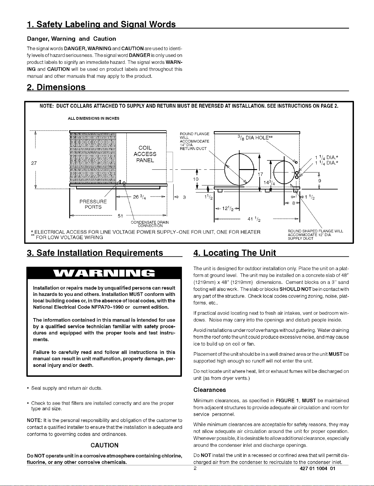
NOTE: DUCT COLLARS ATTACHED TO SUPPLY AND RETURN MUST BE REVERSED AT INSTALLATION. SEEINSTRUCTIONS ON PAGE 2.
ALL DIMENSIONS IN INCHES
ROUND FLANGE
WILL 3/8 DIA HOLE**
ACCOMMODATE
COIL
ACCESS
27
" tl_ I
PANEL
PRESSURE
26 3/4
<i PORTS
* ELECTRICAL ACCESS FOR LINE VOLTAGE POWER SUPPLY-ONE FOR UNIT, ONE FOR HEATER
** FOR LOW VOLTAGE WIRING
81 \
CONDENSATE DRAIN
CONNECTION
14" DIA.
RETURN DUCT
m___
10 9
3 11/2 I-1 1/2
41 1/2
ROUND SHAPED FLANGE WILL
ACCOMMODATE 12" DiA
SUPPLY DUCT
. 1 1/4 DIA.*
/ 1 1/4 DIA.*
3. Safe Installation Requirements 4. Locating The Unit
The unit is designed for outdoor installation only. Place the unit on a plat-
form at ground level. The unit may be installed on a concrete slab of 48"
Installation or repairs made by unqualified persons can result
in hazards to you and others. Installation MUST conform with
local building codes or, in the absence of local codes, with the
National Electrical Code NFPA70-1990 or current edition.
The information contained in this manual is intended for use
by a qualified service technician familiar with safety proce-
dures and equipped with the proper tools and test instru-
ments.
Failure to carefully read and follow all instructions in this
manual can result in unit malfunction, property damage, per-
sonal injury and/or death.
• Seal supply and return air ducts.
• Check to see that filters are installed correctly and are the proper
type and size.
NOTE: It is the personal responsibility and obligation of the customer to
contact a qualified installer to ensure that the installation is adequate and
conforms to governing codes and ordinances.
CAUTION
Do NOT operate unit in a corrosive atmosphere containing chlorine,
fluorine, or any other corrosive chemicals.
(1219mm) x 48" (1219mm) dimensions. Cement blocks on a 3" sand
footing will also work. The slab or blocks SHOULD NOT be in contact with
any part ofthe structure. Check local codes covering zoning, noise, plat-
forms, etc..
If practical avoid locating next to fresh air intakes, vent or bedroom win-
dows. Noise may carry into the openings and disturb people inside.
Avoid installations under roof overhangs without guttering. Water draining
from the roof onto the unit could produce excessive noise, and may cause
ice to build up on coil or fan.
Placement ofthe unit should be in a well drained area or the unit MUST be
supported high enough so runoff will not enter the unit.
Do not locate unit where heat, lint or exhaust fumes will be discharged on
unit (as from dryer vents.)
Clearances
Minimum clearances, as specified in FIGURE 1, MUST be maintained
from adjacent structures to provide adequate air circulation and room for
service personnel.
While minimum clearances are acceptable for safety reasons, they may
not allow adequate air circulation around the unit for proper operation.
Whenever possible, itis desirable to allowadditional clearance, especially
around the condenser inlet and discharge openings.
Do NOT install the unit in a recessed or confined area that will permit dis-
charged air from the condenser to recirculate to the condenser inlet.
2 427 01 1004 01

Minimum Clearances to Combustible Construction
SERVICE ACCESS CLEARANCES
Blower Access Panel Side .......................... 30" (762mm)
Electrical Access Panel Side ........................ 30" (762mm)
OPERATIONAL CLEARANCES
Combustible Base
(Wood or Class A, B or C
roof covering material) ......................... 0"
Supply and Return Air Ducts ................................. 0"
Duct Connection Side
............................................. 0 !_
Clearance between Overhang
Clearance around Condenser Coil area to wall or shrubs ........ 10"
FIGURE i Minimum Clearances and Access Panels
Evaporator 48" Minimum Overhang Clearance
Access Panel
and Top of Unit ..................... 48" (1219mm)
Overhang
J
10"around
f condenser
coil area
Installing Duct Collars
Duct collars are supplied with the unit and are attached to the supply and
return openings with the flanges tothe inside and must be reversed before
unit's installation.
Blower/Electrical
Access Panel
,,_ Cover Plate
Installation
CAUTION
The unit must be installed with a slope no greater than 1/8" per foot
(10mm per meter), For side to side leveling, the condensate drain
side side MUST always be lower.
The unit MUST be situated in such a way as to provide safe access
for servicing.
The platform may be made of either concrete or pressure treated
wood and MUST be level and strong enough to support the unit's
weight.
1.Remove the screws from the collars and reverse them so the flange
is to the outside.
2.Make sure when pushing the collars into place that the "V" flange of
the collars seats into the supply and return holes securely.
3.Re-install screw in each collar so it goes through both of the holes in
the collar end. It does not matter how the ends of the collar overlap
in order to accomplish this.
FIGURE ;3 I Duct Collar Installation
Position platform separate from the building's foundation.
Install in a well-drained area, with the top surface of the platform
above grade level and above the average winter snow levels to
prevent coil blockage.
Platform MUST be high enough to allow for proper condensate
drainage.
3 427 01 1004 01
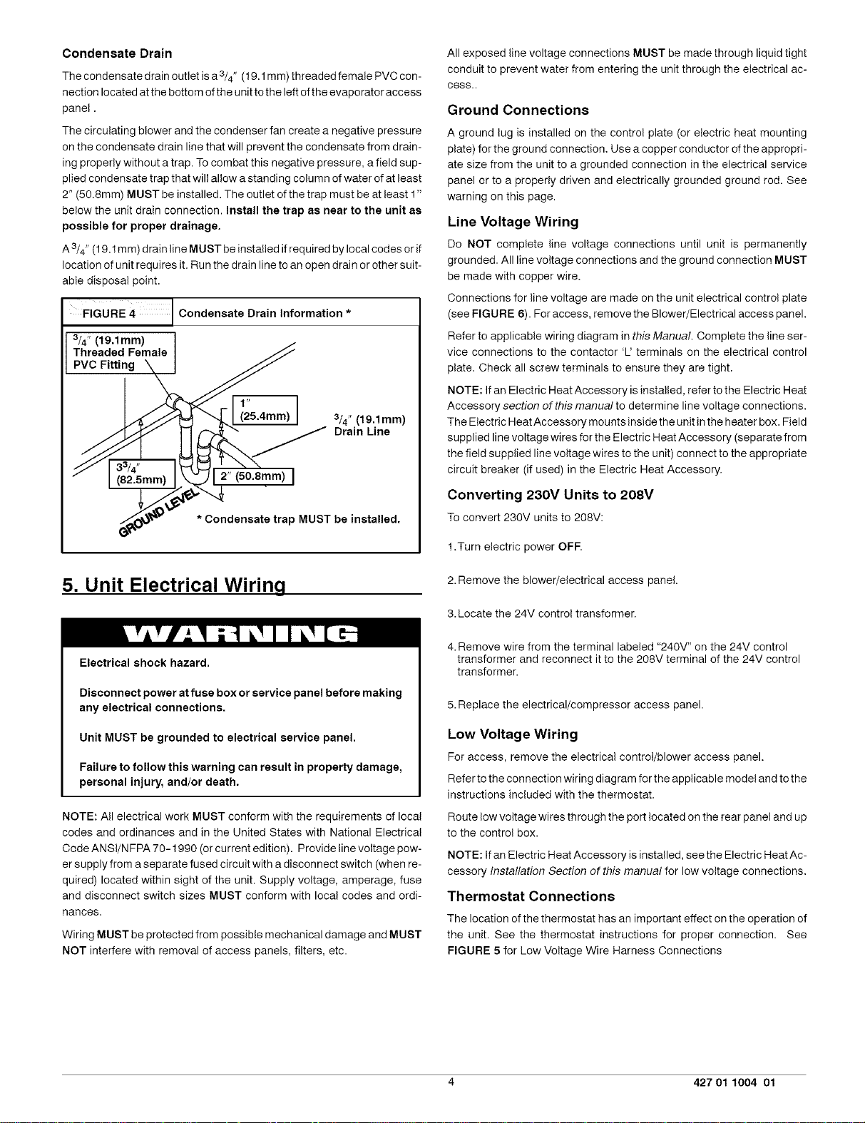
Condensate Drain
The condensate drain outlet is a 3/4" (19.1 mm) threaded female PVC con-
nection located at the bottom ofthe unit to the left of the evaporator access
panel.
The circulating blower and the condenser fan create a negative pressure
on the condensate drain line that will prevent the condensate from drain-
ing properly without a trap. To combat this negative pressure, a field sup-
plied condensate trap that will allow a standing column of water of at least
2" (50.8mm) MUST be installed. The outlet of the trap must be at least 1"
below the unit drain connection. Install the trap as near to the unit as
possible for proper drainage.
A 3/4" (19.1 mm) drain line MUST be installed ifrequired by local codes or if
location of unit requires it. Run the drain line to an open drain or other suit-
able disposal point.
FIGURE 4 J Condensate Drain information*
3/4" (19,1mm)
Threaded Female
PVC Fitting
i
1,, I
(25.4mm)
3/4" (19.1mm)
Drain Line
All exposed line voltage connections MUST be made through liquid tight
conduit to prevent water from entering the unit through the electrical ac-
cess..
Ground Connections
A ground lug is installed on the control plate (or electric heat mounting
plate) for the ground connection. Use a copper conductor of the appropri-
ate size from the unit to a grounded connection in the electrical service
panel or to a properly driven and electrically grounded ground rod. See
warning on this page.
Line Voltage Wiring
Do NOT complete line voltage connections until unit is permanently
grounded. All line voltage connections and the ground connection MUST
be made with copper wire.
Connections for line voltage are made on the unit electrical control plate
(see FIGURE 6). For access, remove the Blower/Electrical access panel.
Refer to applicable wiring diagram in this Manual. Complete the line ser-
vice connections to the contactor 'U terminals on the electrical control
plate. Check all screw terminals to ensure they are tight.
NOTE: If an Electric Heat Accessory is installed, refer to the Electric Heat
Accessory section of this manual to determine line voltage connections.
The Electric HeatAccessory mounts inside the unit in the heater box. Field
supplied line voltage wires for the Electric Heat Accessory (separate from
the field supplied line voltage wires to the unit) connect to the appropriate
circuit breaker (if used) in the Electric Heat Accessory.
* Condensate trap MUST be installed.
5. Unit Electrical Wiring
Electrical shock hazard.
Disconnect power at fuse box or service panel before making
any electrical connections.
Unit MUST be grounded to electrical service panel.
Failure to follow this warning can result in property damage,
personal injury, and/or death.
NOTE: All electrical work MUST conform with the requirements of local
codes and ordinances and in the United States with National Electrical
CodeANSI/NFPA 70-1990 (orcurrent edition). Providelinevoltage pow-
er supply from a separate fused circuit with a disconnect switch (when re-
quired) located within sight of the unit. Supply voltage, amperage, fuse
and disconnect switch sizes MUST conform with local codes and ordi-
nances.
Wiring MUST be protected from possible mechanical damage and MUST
NOT interfere with removal of access panels, filters, etc.
Converting 230V Units to 208V
To convert 230V units to 208V:
1.Turn electric power OFF.
2.Remove the blower/electrical access panel.
3. Locate the 24V control transformer.
4. Remove wire from the terminal labeled "240V" on the 24V control
transformer and reconnect it to the 208V terminal of the 24V control
transformer.
5. Replace the electrical/compressor access panel.
Low Voltage Wiring
For access, remove the electrical control/blower access panel.
Referto theconnectionwiringdiagramfor the applicablemodeland tothe
instructions included with the thermostat.
Route low voltage wires through the port located on the rear panel and up
to the control box.
NOTE: Ifan Electric Heat Accessory is installed, see the Electric Heat Ac-
cessory Installation Section of this manual for low voltage connections.
Thermostat Connections
The location of the thermostat has an important effect on the operation of
the unit. See the thermostat instructions for proper connection. See
FIGURE 5 for Low Voltage Wire Harness Connections
4 427 01 1004 01
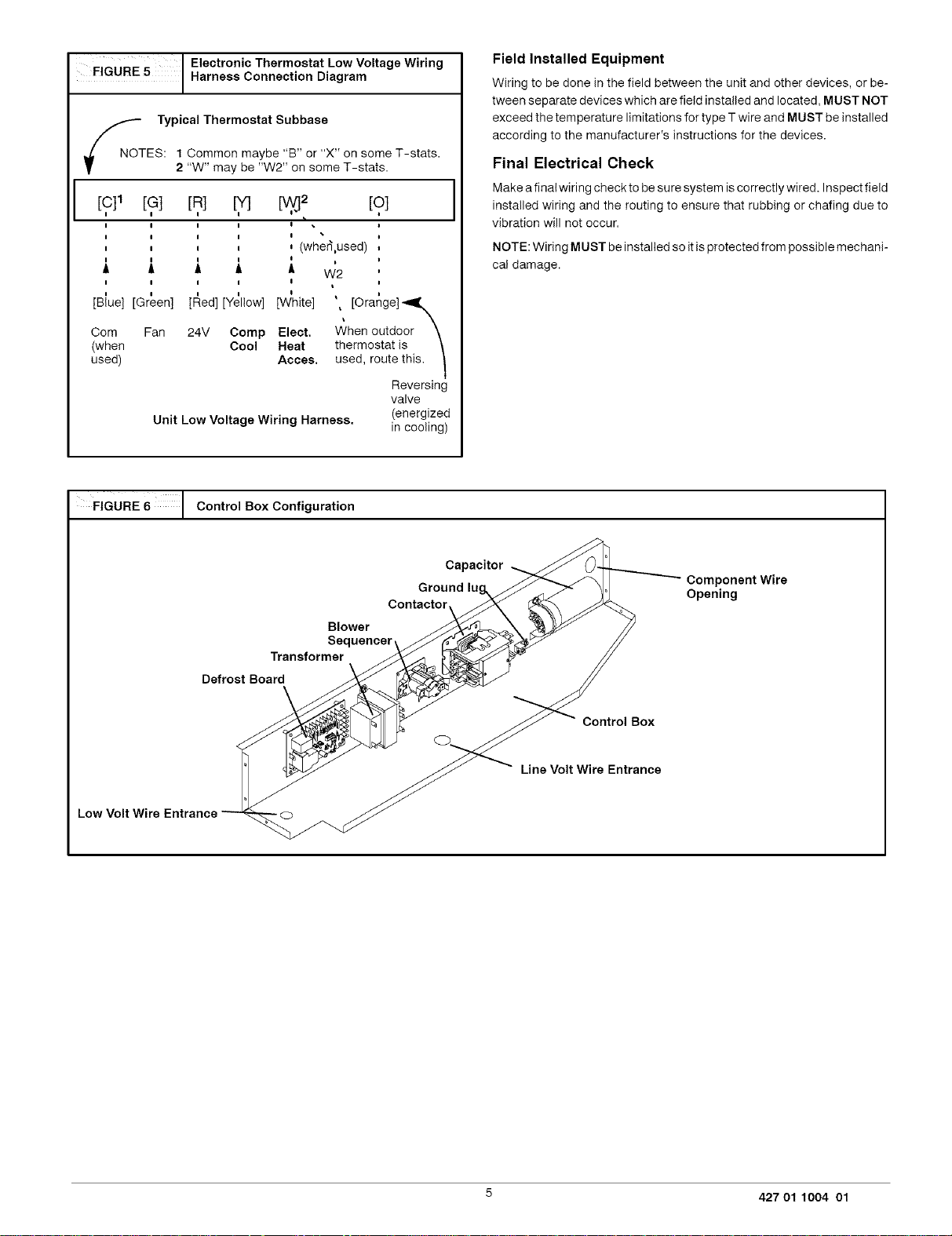
FIGURE5 I HarnessElectr°niCconnectionTherm°statDiagramL°WVoltage Wi ri ng
_NOT Typical Thermostat SubbaseES: 1 Common maybe "B" or "X" on some T-stats.
[c]1
I
i
I I I I
I I I I /
A A A A
I I I I I
[Blue] [Green] [F_ed] [Yellow] [W_hite]
Corn Fan 24V Comp Elect.
(when Cool Heat
used) Acces.
FIGURE 6 I Control Box Configuration
2 "W" may be "W2" on some T-stats.
[?] [,R] [O]
I I I I
I I I I
Unit Low Voltage Wiring Harness.
i (wher],used)
A
W2
',, [Orange] "_,Xk
When outdoor \
thermostat is \
used, route this. I
valve
Reversing
(energized
in cooling)
Field Installed Equipment
Wiring to be done in the field between the unit and other devices, or be-
tween separate devices which are field installed and located, MUST NOT
exceed the temperature limitations for type T wire and MUST be installed
according to the manufacturer's instructions for the devices.
Final Electrical Check
Make a final wiring check to be sure system is correctly wired. Inspect field
installed wiring and the routing to ensure that rubbing or chafing due to
vibration will not occur.
NOTE: Wiring MUST be installed so itis protected from possible mechani-
cal damage.
i
Low Volt Wire Entrance
Capacitor_
Ground lug%__ _oJ Component Wire
Contaotor Opening
Blower J___ _ //
Sequencer __;_ /_
Transformer\ ____. F //
oooooox
,neVo,We n,anoe
5 427 01 1004 01
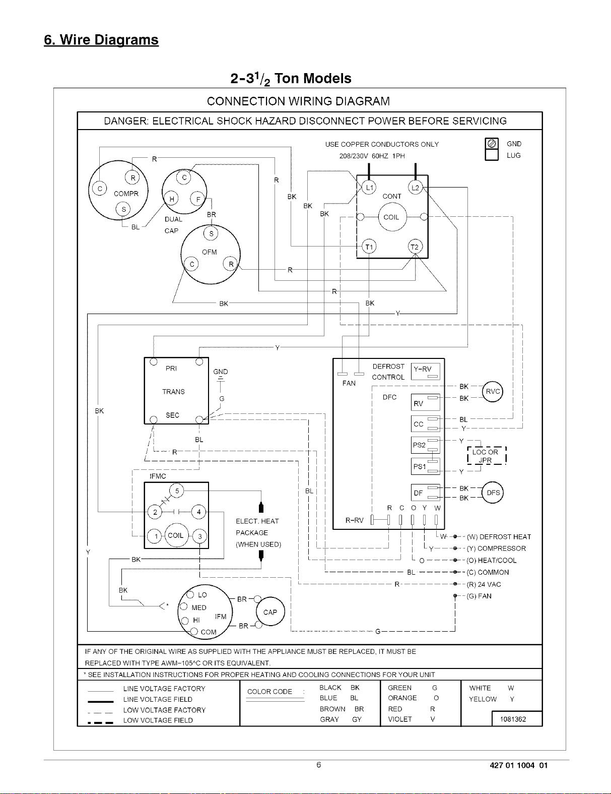
6. Wire Diagrams
DANGER: ELECTRICAL SHOCK HAZARD DISCONNECT POWER BEFORE SERVICING
DUAL
CAP
2-31/2 Ton Models
CONNECTION WIRING DIAGRAM
USE COPPER CONDUCTORS ONLY
208/230V 60HZ 1PH
EK
_ CONT
BK
BK
BK
B ND
LUG
4-
BK
PRt
TRANS
SEC
I...........R I
I IFMC
I
Ltc 3b
BK I
BK
I
BL
I
ELECT. HEAT
PACKAGE
(WHEN USED)
I
I
I
I
I
I
_q
I
L _ J
I
FAN
R-RV
DEFROST
CONTROL
DEC
R C
O Y W
I
I I
I I Lw+_ (w) DEFROST HEAT
I
I
I L y (y) COMPRESSOR
L O -------e--(O) HEAT/COOL
BL .... -e-- (C) COMMON
R e- (R) 24 VAC
<*
BR
tF ANY OF THE ORIGINAL WIRE AS SUPPLIED WITH THE APPLIANCE MUST BE REPLACED, IT MUST BE
REPLACED WITH TYPE AWM-105 C OR ITS EQUIVALENT.
* SEE INSTALLATION INSTRUCTIONS FOR PROPER HEATING AND COOLING CONNECTIONS FOR YOUR UNIT
LINE VOLTAGE FACTORY COLOR CODE : BLACK BK GREEN G
/ LINE VOLTAGE FIELD BLUE BL ORANGE O
LOW VOLTAGE FACTORY BROWN BR RED R
= i i LOW VOLTAGE FIELD GRAY GY VIOLET V
A
...............................................................................................G •
BL
Y
Yr&---i
LOC OR
L_P___!
y •
(G) FAN
I
I
I
WHITE W
YELLOW Y
6 427 01 1004 01

Wire Diaqrams (Cont'd...)
DANGER: ELECTRICAL SHOCK HAZARD DISCONNECT POWER BEFORE SERVICING
2-31/2 Ton Models
LADDER WIRING DIAGRAM
Lt _!1 GNU L2
(OPTIONAL) CRANKCASE HEATER
L1 CONTACTOR T1 CONTACTOR L2
208/230 VAC, 60 HZ, 1PH m
CAP
COMPR
DFC
_ OFM
<*
_CAP
IFM
230V
_...___) 208V TAP
TRANS
O
+
I
I
I
TRANS....TRANSFORMER
COMPR....COMPRESSOR
CAP ........ CAPACITOR
CONT......CONTACTOR
JPR ........ JUMPER WIRE
FAN
DEFROST
CONTROLDFs _
F ...................................................................................
R-_ i I f O Y W
mv _U I_
I L_--e- .... (W) DEFROST HEAT
I j ....
I e- .... (Y) COMPRESSOR
L
................................e ................................(O) HEAT/COOL
(C) COMMON -_.
(G) FAN .....
[ ,_EGE,,,o]
GND.......GROUND
LOC.......LOSS OFCHARGE
PRESSURESWtTCH
DFS ........ DEFROST SENSOR
DFC ........ DEFROST CONTROL
24V
......!_ LOC OR_ I
[ I JPR _i
ZZZZ@ _
e- .... (R) 24 VAC
E
IFMC......tNDOOR FAN MOTOR CONTROL
IFM ........ iNDOOR PAN MOTOR
RVS ........ REVERSING VALVE SOLENOID
OFM ........ OUTDOOR PAN MOTOR
TC .......... TERMINAL CONNECTOR
+
GND _
I 1081362
7 427 01 1004 01

Wire Diaqrams (Cont'd...)
DANGER: ELECTRICAL SHOCK HAZARD DISCONNECT POWER BEFORE SERVICING
4 & 5 Ton Model
CONNECTION WIRING DIAGRAM
R
BL _ C,_
_) {} Y
TRANS
BK
--BK I
BK
O SEC O _ _/
/I t
//EE BL
/ L_ R- I
I IPMC
I
I ELECT. HEAT
L_ PACKAGE
L
\
PRI GND
J
I
I
I
BK
G
(WHEN USED)
BR
USE COPPER CONDUCTORS ONLY
208/230V 6OHZ 1PH
BK
BK
BK
I I
I I
I I
I I
BK
i• L>--'@,--C \
I
FAN
I
Tq I
1 I I
I I I
I I I
I I I
i BLI I
I I I I
I I I I
I I I
I I I
I I I
I I Lw+ (W) DEFROSTHEAT
I I I
I I I
I I
L
I ] L O --- ÷- (O) HEAT/COOL
I
I BL .... ÷ (C) COMMON
I
I L R ....................................................................._ (R) 24 VAC
I
I _ (G)FAN
I I
I I
R-RV
I
CONT '_
DEFROST
CONTROL
r
ii DFC _
I
I
I
I
I
I
I
I
I
I
I
I
I
I R C O Y W
I
I
J
Ly + (Y) COMPRESSOR
BK
y--_
I I
I G I
B
GND
LUG
I
I
I
I
I
I
I
I
I
I
I
I
I
I
I
I
I
I
I
I
I
I
I
I
I
I
I
I
I
I
I
I
I
I
I
IF ANY OF THE ORIGINAL WiRE AS SUPPLIED WITH THE APPLIANCE MUST BE REPLACED, IT MUST BE
REPLACED WITH TYPE AWM-165 C OR ITS EQUIVALENT.
* SEE INSTALLATION INSTRUCTIONS FOR PROPER HEATING AND COOLING CONNECTIONS FOR YOUR UNIT
LINE VOLTAGE FACTORY COLOR CODE : BLACK BK GREEN G
LINE VOLTAGE FIELD ..................................................................BLUE BL ORANGE O
LOW VOLTAGE FACTORY BROWN BR RED R
= m m LOW VOLTAGE FIELD GRAY GY VIOLET V
^
8 427 01 1004 01
WHITE W
YELLOW Y
I 1081364

Wire Diagrams (Cont'd...)
DANGER: ELECTRICAL SHOCK HAZARD DISCONNECT POWER BEFORE SERVICING
4 & 5 Ton Model
LADDER WIRING DIAGRAM
L1
(OPTIONAL) CRANKCASE HEATER I _ I
L1 CONTACTOR T1 COMPR T2 CONTACTOR L2
O---_ II GND L2
208/230 VAC, 60 HZ, 1PH |
4 CA H
O _ C FM
DFC SCO
[ <
TRANS
TRANS....TRANSFORMER
COMPR....COMPRESSOR
CAP ........ CAPACITOR
CONT......CONTACTOR
JPR ........ JUMPER WIRE
FAN
DEFROST
CONTROLDFs _
F
R-[_R If O Y W
RV _1_
(C) COMMON ..... -e
GND.......GROUND
LOC_.....LOSS OF CHARGE
PRESSURE SWITCH
DFS ........ DEFROST SENSOR
DFC ........ DEFROST CONTROL
I I ...............e ...........................(W) DEFROST HEAT
I
I _ (Y) COMPRESSOR
L .... -e- .... (O) HEAT/COOL
(G) FAN .........................................._ ............................................................................................................................
LEGEND
jq _2P2_ )
ZZZZ@ _
4_ (R) 24 VAC
J
IFMC......tNDOOR FAN MOTOR CONTROL
IFM........ INDOOR FAN MOTOR
RVS ........REVERSING VALVE SOLENOID
OFM ........ OUTDOOR FAN MOTOR
TC.......... TERMINAL CONNECTOR
}
/
()
(,)
GND L
I 1081364
9 427 01 1004 01

7. Electric Heat Installation General
Information
8. Installing Electric Heat Accessory
General Information
Installation or repairs made by unqualified persons can result
in hazards to you and others. Installation must conform with
local building codes or, in the absence of local codes, with
National Electrical Code ANSI/NFPA 70-1990 or current
edition.
The information contained in this manual is intended for use
by a qualified service technician familiar with safety
procedures, equipped with the proper tools and test
instruments.
Failure to carefully read and follow all instructions in this
manual can result in malfunction, property damage, personal
injury, and/or death.
When an electric heat accessory is installed, two separate field power
supplies MUST be provided - one or more for the electric heat accessory
and one for the unit.
Electrical shock hazard.
Shut OFF electric power at unit disconnect and/or service
panel before beginning the following procedures.
Failure to follow this warning can result in property damage,
personal injury, and/or death.
1. Shut OFF electric power at unit disconnect switch or service panel.
2. Remove the blower access panel from unit.
NOTE: Installation of field wiring and conduit for heaters to the
unit prior to installing the heater will simplify wiring of heaters.
3. From inside the blower compartment, remove the six screws on the
heater cover plate and save the screws. Discard the heater cover
plate.
The screws will be used later to mount the electric heat accessory
and its cover.
4. Remove the cardboard wrapper from the heater's elements.
5.Insert the heater into the heater/blower box. Exercise caution to
prevent damage to heater elements.
&Secure heater to heater/blower box with four of the six screws re-
moved in Step 3.
FIGURE 7 The Electric Heat Accessory
Breaker-
FIGURE 8 Installing The Electric Heat Accessory
10 427 01 1004 01

9. Heater Electrical Wirinq
Electrical shock hazard.
Shut OFF electric power at unit disconnect or service panel
before making any electrical connections.
Unit MUST be grounded before making line voltage connec-
tions. Do NOT fuse ground or neutral conductors.
Failure to follow this warning can result in property damage,
personal injury, and/or death.
NOTE: All electrical work MUST conform with the requirements of local
codes and ordinances and in the United States with National Electrical
Code ANSI/NFPA70-1990 or current edition. Provide line voltage power
supply from a separate protected circuit with a disconnect switch (when
required) located within sight ofthe unit. Supply voltage, amperage, fuse
and disconnect switch sizes MUST conform with all technical specifica-
tions in this manual and on the unit rating plate and local codes.
Wiring MUST be protected from possible mechanical damage and MUST
NOT interfere with removal of access panels, filters, etc.
All exposed wiring or connections MUST be made with weatherproof
cable or wire unless installed in conduit.
All line voltage connections and the ground connection MUST be made
with copper wire.
The power supply wiring MUST have overcurrent protection. This can be
either fuses or circuit breakers. The maximum size for the overcurrent
protection is shown in the column labeled "Max. Fuse or NEC HACR
Breaker (Amps)" in the Electrical Data Table in FIGURE 10 or on the unit
rating plate.
Grounding
Permanently ground the electric heat accessory in accordance with local
codes and ordinances and in the United States with National Electrical
Code ANSI/N FPA70-1990 or current edition. Use a copper conductor of
the appropriate size from the electric heat accessory to the ground lug on
the circuit breaker panel as shown in FIGURE 9.
Adjusting Thermostat Anticipator
Set theheatanticipator of the thermostattothe propervalue. See instruc-
tions providedwith the thermostat before making this adjustment.
Model Number Anticipator
AMMK05AHB/A .18
AM MK07AH B/A .36
AMMK10AH B/A .36
AMMK15AH B/A .36
AM MK20AH B/A .54
Setting
Limit Controls
The limit controls are mounted on the face of the heater and are wired into
the supply wires to each element. If there is not enough air flow through
the heater, the limit will open and break the power circuit. The limit will re-
set when the electric accessory cools down.
Time Delay Operation
The heater elements are switched ON and OFF through one or more con-
trois which operate through the low voltage thermostat circuit.
These controls consist of a number of time delays depending on the spe-
cific heater model. An electric heat accessory has 1,2 or 3 of these con-
trois. The first time delay is activated when the thermostat contacts close.
Approximately 1 to 20 seconds later the indoor blower and the first heater
bank are energized. Approximately 70 seconds after the first heater bank
is energized the remaining time delays and heater banks are energized.
Staging
Some electric utilities require staging on electric heaters larger than 6 kilo-
watts. Therefore, the heater elements are turned on in 5 or 10 kW incre-
ments under control of the sequencers.
If staging based on heat loss or demand is required, the use of accessory
outdoor thermostats is recommended. The heat sequencer wiring is de-
signed to be staged by breaking the 24V "Common" Leg (normally brown
or gray). Outdoor thermostats available through your wholesale supplier
allow the control of two or four stages of electrical heat.
Some indoor electronic thermostats may provide for multiple stage of
electric heat. When this type thermostat is used, it may be necessary to
break the 24V"Hot" leg of the sequencer (asfed from the "W' circuit at the
thermostat). This will require field modification of the control wiring and
should only be done byan experienced controls technician/or electrician.
Installing Wiring
1.Shut OFF electric power at unit disconnect or service panel.
2.Install the appropriate field supplied conduit fitting into the heater
knockout located in the rear panel of the unit. The wiring entrance
hole is sized for 1" conduit.
11 427 01 1004 01

TypicalWiringInstallation(BreakerStyleHeaterShown-Pigtailstylealsoavailable)
UnitLineVoltageWires
3.Connect field installed copper ground wire(s) to the ground lug(s) on
the heater mounting plate. On models with more than one circuit, a
separate copper ground wire MUST be connected to a separate
ground lug for each circuit.
4. Route the field supplied line voltage wires for the heater to the line
side of the electric heat accessory's circuit breaker(s) or high voltage
wiring harness. Leave approximately 8" of excess wire so the break-
er or wiring harness may be moved to service. Make line voltage
connections to L3-L6 as appropriate. NOTE: If heaters without
breakers are used, route field wires to inside of unit and attach to
heater wires tagged L3-L6 as appropriate using supplied wire nuts.
5.Connect the black wire with terminal from the heater wire harness to
the loose black wire at the unit blower.
NOTE: Check FIGURE 11 for heater/speed combinations that are
unacceptable.
6 Connect the red wire with terminal in the heater wire harness to the
loose red wire from the unit sequencer.
7. Connect the white wire from the heater wire harness to the white wire
from the thermostat at the field supplied low volt wire harness in the
control box.
8. Connect the grey and brown wires from the heater wire harness to
the blue wire from the unit 24V common. NOTE: If outdoor thermo-
stats are used for staging electric heat, connect the grey and brown
wires according to the thermostat instructions. See "Staging" in
Electrical Wiring Section of this Manual.
After completing installation of the heater, install the breaker rain shield on
the blower access panel according to the following instructions on page
13. If using a pigtail style heater, proceed to Start-Up Procedures for Aux-
iliary Electric Strip Heat on page 14.
12 427 01 1004 01

FIGURE10 AccessoryElectricHeaterElectricalData
HEATER
MODEL
AMMK05AHA
AMMK05AHB
AMMK07AHA
AMMK07AHB
AMMK10AHA
AMMK10AHB
AMMK15AHB
AMMK20AHB
UsedWith
2-5 TON
2-5 TON
2-5 TON
21/2-5 TON
21/2-5 TON
Supply Voltage
240-1-60
208-1-60
240-1-60
208-1-60
240-1-60
208-1-60
240-1-60
208-1-60
240-1-60
208-1-60
KWRating
4.8
3.6
7.5
5.6
9.6
7.2
14.4
10.8
19.2
14.4
Nominal Heating
BTUH
16,382
12,287
25,598
19,113
32,765
24,574
49,147
36,860
65,530
49,147
Supply
Circuit No,
L3-L4
L3-L4
L3-L4
L3-L4
L3-L4
L5-L6
L3-L4
L5-L6
L3-L4
L5-L6
L3-L4
L5-L6
L3-L4
L5-L6
Heater
Amps
20.0
17.3
31.2
26.9
40.0
34.6
40.0
20.0
34.6
17.3
40.0
40.0
34.6
34.6
MininumCircuit
Ampacity
25.0
21.6
39.1
33.6
50.0
43.3
50.0
25.0
43.3
21.6
50.0
50.0
43.3
43.3
MaximumOvercurrent
ProtectiveDevice
(Amps)
3O
25
45
4O
6O
5O
6O
3O
5O
25
6O
6O
5O
5O
FIGURE 11
Accessory Electric Heater Heating Data
*TemperatureRise °F @CFM(ElectricHeatOnly)
Heater
Model
AMMK05AHA
AMMK05AHB
AMMK07AHA
AMMK07AHB
AMMK10AHA
AMMK10AHB
AMMK15AHB*
AMMK20AHB**
UseWith
2-5 TON
2-5 TON
2-5 TON
21/2-5 TON
21/2-5 TON
Supply Voltage
240-1-60
208-1-60
240-1-60
208-1-60
240-1-60
208-1-60
240-1-60
208-1-60
240-1-60
208-1-60
KWRating
4.8
3.6
5.6
9.6
14.4
10.8
19.2
14.4
7.5
7.2
Total Heating
BTUR 600 800
16,832 25.3 19.0
12,287 19.0 14.2
25,598 39.5 29.6
19,113 29.5 22.1
32,765 50.6 37.9
24,574 37.9 28.4
49,147 --- 56.9
36.860 56.9 42.7
65,530 ......
49,147 --- 56.9
* 15KW HEATERNOTTOBE OPERATEDONLOWTAPFOR 21/2 TONA/C ANDHE
** 20KW HEATERNOTTOBE OPERATEDONLOWOR MEDIUMLOWTAP FOR3 AND3 1/2A/C AND HE
1000 1200 1400 1600 1800 2000 2200
15.2 12.6 10.8 9.5 8.4 7.6 ---
11.4 9.5 8.1 7.1 6.3 5.7 ---
23.7 19.8 16.9 14.8 13.2 11.9 10.8
17.7 14.7 12.6 11.1 9.8 8.8 8.0
30.3 25.3 21.7 19.0 16.9 15.2 13.8
22.8 19.0 16.3 14.2 12.6 11.4 10.3
45.5 37.9 32.5 28.4 25.3 22.8 20.7
34.1 28.4 24.4 21.3 19.0 17.1 15.5
--- 50.6 43.3 37.9 33.7 30.3 27.6
45.5 37.9 32.5 28.4 25.3 22.8 20.7
13 427 O1 1OO4 O1

Wire Diagrams - Electric Heat Accessory
DESCRIPTION: IWIRING CODE_ REVISION_
AM[vlK 5_7.5,18 & 15 KS! ELECTRIC HEAT [ 2£18/23_1V88 HZ 1 PH
AHB HEATERS ONLY I • ] i
20B/24BV 1PH 60 HZ ] I I
USE COPPER CONDUCTORS ONLY I i!
FAN CONTACTOR _---_
CONTROL ?_ ....
TO U ; , ,
G s :I , _ ] ,,
:DMMON..... BL r • ' '
TO L2 BR ONO
COmnCTOR_ _ CONNEmlONS
_" TMERMOmAT
,,J/', i\N
ELECTRICAL SHOCK HAZARD
DISCONNECT ALL POWER SUPPLIES.
FAILURE TO DO SO COULD RESULT
SERIOUS INJURY OR DEATH.
EL .......... ELECTRIC ELEMENT
SEQ........SEQUENCER
HTR........HEATER
GND,,,,.,,,GROUND
LS .......... LIMIT SWITCH
[FM..,.....[NOOOR FAN MOTOR
GY
TRANS..,.TRANSFORMER
[FMC,.....,INDOOR FAN MOTOR CONTROL
FOLLOW HEATER INSTAL
LATIDN INSTRUCTIONS
ACCESSORYHEATER
WIRE MARNESS WIRING
LEGEND
LOW VOLTAGE
LINE VOLTAGE
HEATERABS¥ FORUSEW,TB,
MODEL NUMBER ELEMENTS _L3 L4 PA55, PA£5 & PH55
AMMKB5AHB 1 25A
AMMK_GAHA 24,30,36,42,48 & 60
AMMKO7AHB
AMMKO7AHA [,2 40A 24,30,36,42,4B & BO
AMMK]OAHB
AMMK]OAHA 1,2 50A 24,30,36,42,48 & 60
AMMK15AHB 112.3 3_,36,42,48 & BO
DESCRIPTION= WIRING CODE: REVISION: PART NUMBER:
AP1P1K 28 KW ELECTRZ8 HEAT 288/230v 1882113B
2BB/240V i PH 6B HZ ,
USE COPPER CONDUCTORS ONLY ,
INTERNALNTERNAL(WHEN_WHENRECOMMENDED
, , ÷ q
COLOR CODE
BLACK BK
BLUE BL
BROWN BR
GRAY GY
ORANGE 0
RED R
VIOLET V
WHITE W
YELLOW y
68 HZ 1 PH
1 ALL WIRING MUST BE DONE IN
2. WIRING THAT IS CIRCLED MUST
3 IF ANY WIRE MUST BE REPLACED,
IN SERIOUS INJURY OR DEATH.
NOTES
ACCORDANCE WITH NATIONAL
AND LOCAL ELECTRICAL CODES.
BE DONE BY INSTALLER
......
,, m /-x
ELECTRICAL SHOCK HAZARD
DISCONNECT ALL POWER SUPPLIES
FAILURE TO DO SO COULD RESULT
EL .......... ELECTRIC ELEMENT
SEO....,,..SEOUENCER
HTR........HEATER
GND....,,..GROUND
LS .......... LIMIT SWITCH
IFN........INDOOR FAN MOTOR
TRANS,...TRANSFORMER
IFMC.,.,...INDOOR FAN MOTOR CONTROL
FOLLOW HEATER INSTAL
LATION INSTRUCTIONS.
LEGEND
L__<_ BK
HEATER ASSY.
MODEL NUMBER ELEMENTS
AMMKO20AHB 4 50A 50A 36,42 & 48
L3 L4 L5 L6
PA55
36,42,48 & 60
PAD5
PH55
36,42,48 & 80
ACCESSORYHEATEa
COLOR CODE
BLACK BK
BLUE BL
BROWN BR
GRAY GY
ORANGE 0
RED R
VIOLET V
WHITE W
YELLOW y
WIREHARNESS WIRING
1. ALL WIRING MUST BE DONE IN
ACCORDANCE WITH NATIONAL
AND LOCAL ELECTRICAL CODES
2. WIRING THAT IS CIRCLED MUST
BE DONE BY INSTALLER
3. IF ANY WIRE MUST BE REPLACED,
IT MUST BE REPLACED WITH ITS
EQUIVALENT, MIN RATING 105°C
NOTES
LOW VOLTAGE
LINE VOLTAGE
14 427 01 1004 01

10. Rain Shield Installation
121 Installing The Rain Shield
I
S,ZE.ADHES,VEBAO D.
l_f_SII I IIL_JI I _ PLACEINSIDE
HEATER PLUGS
RAIN SHIELD
connected to anexisting system, the ductwork MUST be checked to make
sure it is adequate. Extra runs or larger duct sizes may have to be
installed.
Maximum recommended velocity in trunk ducts is 1000 feet per minute
(5.08m/s). Velocity in branches should not exceed 800 feet per minute
(4.06m/s). Refer to the TechnicalData Label on the unit for unit air volume
requirements and system sizing recommendations.
NOTE: Ductwork sizing affects temperature rise and cooling temperature
differential. Be sure to properly size ductwork to the capacity and airflow
characteristics of your unit. Failure to do so can affect limit controls, com-
pressors, motors, and other components and will lead to premature failure
of components. This will also adversely affect day to day unit perfor-
mance.
Flexible Duct Kits are available from your supplier to effect proper sizing
and installation to Mobile Homes and other standard construction..
Refer to unit rating plate for proper Electric Heat Accessory sizing and see
the Temperature Rise Check section inthe Electric Heat Accessory Instal-
lation Section of this manual.
1.Removeallscrewsfrom the cover plateon Blower/ElectricalAccess Panel.
2. Install adhesive backed gasket on Blower/Electrical Access Panel.
3.Install lower frame of rain shield with 4 screws.
4.Install rain shield hinged cover with 4 screws.
5. Install circuit breaker filler plates (2 each per unused breaker slot.)
6. Re-install Blower/Electrical Access Panel.
NOTE: VERIFY ALL APPROPRIATE SEALS ARE IN PLACE. SEE
FIGURE 12,
11. Air Distribution System
For airflow data (blower performance data, blower speed tap settings,
etc.) see the Technical Data Sheet attached to the unit..
Ductwork
NOTE: The total heat gain of the structu reto be conditioned as expressed
in total Btu/hr should be calculated by manufacturer's method or in accor-
dance with "A.S.H.R.A.E. Guide" or "Manual J - Load Calculations" pub-
lished by the Air Conditioning Contractors of America. The total heat gain
calculated should be equal to or less than the cooling capacity output
based on D.O.E. test procedures, steady state efficiency times input.
Ductwork, supply registers, and return air grilles MUST be designed and
sized to handle the unit's cooling air volume requirements. If the unit is
FIGURE 13 Recommended Filter Sizes
NOTE: Some filters are marked with an arrow to indicate the proper direction of air flow through the filter. The air flow direction will be towards
Nominal Tons
Air Conditioning
2
2 1/2
3
3 1/2
4
5
the blower motor. Make sure filter is installed correctly.
Nominal Air Flow
Cubic Feet
per Minute
700-900
900-1100
1100-1300
1300-1500
1500-1700
1900-2100
Ductwork Insulation
It is recommended that ductwork installed outdoors have aminimum of 2"
(51mm) of fiberglass insulation and be covered by a weatherproof vapor
barrier that is protected against damage. Caulking and flashings, or other
means adequate to provide a permanent weather seal, must be used.
It is recommended that ductwork installed in attics orother areas exposed
to outdoor temperatures have a minimum of 2" (51mm) fiberglass insula-
tion and have an indoor type vapor barrier.
Ductwork Connections
The use of flexible, non-combustible connectors between main trunk
ducts and supply and return air plenums is recommended to minimize
vibration transmission.
NOTE: Connect supply and return air plenums to unit in a manner that will
allow the top of the unit to be removed without removing plenums. Ple-
nums MUST be individually sealed to unit casing. Ducts MUST be termi-
nated inside structure.
Filters
All return air MUST pass through a field supplied filter before entering the
unit. If used, an electronic air cleaner MUST be installed in the return air
ductwork. Minimum recommended filter areas are listed in FIGURE 13
and are based on a velocity of 300 ft/min (1.2m/s) for disposable filters
and 500 ft/min (2.54m/s) for washable high velocity filters.
CAUTION
Do NOT operate the unit without all filters in place.
Recommended Filter Sizes
Sq. In. Surface Area/Nominal Size
Disposable Filters
400 or 20 x 25
487 or 20 x 30
576 or 14 x 25 (2Req.)
665 or 16 x 25 (2Req.)
753 or 20 x 25 (2 Req.)
960 or 20 x 30 (2 Req.)
15
Cleanable Filters
246 or 15 x 20
301 or14x25
356 or16x25
411 or 20 x25
466 or 20 x 25
575 or 24 x 25
427 01 1004 01

12. Start-up Procedures
Electrical shock hazard.
Use extreme care during all of the following checks and pro-
cedures.
Make sure electric power is turned OFF as instructed in ap-
propriate steps.
Failure to follow this warning can result in property damage,
personal injury, and/or death.
Circulating Air Blower
FIGURE 15 I Blower Motor Speed Taps
I
Blower Speed Tap Block
Yellow
Determining Blower Speed
1.Turn electric power OFF.
2. From the system design, determine the total external static pressure
(ESP) for the supply ducts, return ducts and registers, diffusers,
grilles, dampers, heaters and filters.
3.To your system ESP determined in Step 2, add 0.05 In. W.C. for a
wet coil.
4.From the system design, determine the desired cooling airflow in
cubic feet per minute (CFM).
5. Locate the unit's Blower Performance Data table on the tech data
label for the unit's voltage. (The tech data sheet is attached to the
evaporator access panel on the unit.) From the table, determine the
speed tap required to achieve the desired airflow.
6.See next section, Speed Taps, to set the blower motor speed termi-
nal block (speed taps) to the cooling speed determined in the pre-
vious steps.
Speed Taps
After determiningtherequired CFMandspeedtapdata fromthe tech data
sheet, follow the steps below to change speeds if necessary.
Auxiliary Electric Heat B
Wire (if used)
connects here
BE SURE TO CHECK BLOWER MOTOR SPEED DATA ON THE
UNITS TECHNICAL DATA LABEL LOCATED ON THE UNIT.
NOTE: On Heat Pumps Electric heater blower wire must be attached to
the same speed tap required for cooling/heat pump operation. See FIG-
URE 11 notes. The yellow lead MUST always be connected to the speed
tap block at the common quick connect terminal. The terminal is identified
as COM.
Refer to FIGURE 15 and the appropriate unit wiring diagram included in
this manual. Wire the black wire to the required speed tap terminal to
achieve required airflow determined in Step 5.
Cooling, Heating (Heat Pump) and Auxiliary
Electric Strip Heat
NOTE: The cooling, heat pump and strip heat airflows are all on the same
speed tap. The refrigerant system requires the same specific CFM for
proper operation in the cooling and the heat pump mode. For this reason,
cooling and heating airflow must be the same. DO NOT SPLIT OUT INTO
A COOLING SPEED AND HEATING SPEED. If auxiliary electric heat is
installed, the auxiliary electric heat blower speed wire must be connected
to the black wire insulated quick connect terminal.
FIGURE i4 L Blower Speed Tap Settings
10 SEER 2 TON MED
10 SEER 21/2 TON MED
10 SEER 3 TON LOW
10 SEER 31/2 TON MED HI
10 SEER 4 TON LOW
10 SEER 5 TON HI
Check Before Starting
1. Check that the blower motor speed terminal block is set to the prop-
er cooling speed. Refer to the unit wiring diagram and the various
airflow tables in this manual.
2. Check to see that clean, properly sized field supplied air filters are
installed in the return air duct.
3. Inspect the inside of the unit to be sure that all wires are in place and
all tools, etc. are removed.
4. Replace all service access panels.
Check the unit's operation as outlined in the following instructions. If any
unusual sparking, odors or noises are encountered, shut OFF electric
power immediately. Recheck for wiring errors, or obstructions in or near
blower motors.
16 427 01 1004 01

Circulating Air Blower
4.Set the thermostat temperature setting as high as it will go.
1.Be sure electric power is OFF.
2.Set thermostat Heat-Cool selector to OFF.
3.Set thermostat fan switch to AUTO.
4.Turn electric power ON. Nothing should start running.
5.Set thermostat fan switch to ON. The circulating air blower should
come ON after a 30 second delay.
6. Reset thermostat fan switch to AUTO. The circulating air blower
should go OFF after a 30 second delay. Nothing should be running.
Cooling
1. Be sure that electric power is OFF.
2. Set thermostat Heat-Cool select to COOL.
3. Adjust thermostat setting to below room temperature.
4. Turn electric power ON. During power application check the follow-
ing:
a. Contactor - Contacts closing
b. Compressor - ON
c. Condenser fan motor - ON
d. Circulating air blower - ON (after delay)
5.Switch the thermostat to OFF, check the following:
a. Contactor contacts opening.
b. Compressor - OFF
c. Condenser fan motor - OFF
d. Circulating blower - OFF (after delay)
5.Turn electric power ON.
6.Operate unit AT LEAST 5 minutes, then check temperature rise.
NOTE: The maximum outlet air temperature for all models is 200°F
(93.350). Maximum temperature rise for electric heat is 60°F (33.350)
If temperature rise is excessive, verify proper airflow through the unit. If
temperature rise is inadequate, check for proper electrical supply to the
heater and verify correct airflow.
7.Set thermostat to normal temperature setting.
8.Turn electric power OFF.
9.Change blower speed tap if 60°F (33.3°0) TemperatureRise was exceeded
andrepeat.
10.Be sure to seal all holes in ducts if any were created during this
process.
Defrost Control Time Interval Adjustment
Electrical shock hazard.
Turn OFF electric power supply at disconnect switch or ser-
vice panel before removing any access or service panel from
unit.
Failure to follow this warning can result in property damage,
personal injury, and/or death.
To adjust defrost interval:
1.Turn off all power to Heat Pump.
2. Remove control box cover.
3. Locate electronic defrost control board.
4.The Defrost Control Board has a jumper plug that can be set at 30, 60,
90 or TEST. Remove the plug and insert on the appropriate 2 pins
indicated by ) on the board.
6.Turn electric power OFF
Auxiliary Heating
NOTE: Repeat circulating air blower procedure above ifAuxiliary Electric
Heat is being installed after unit has been installed and checked out.
Temperature Rise Check
Temperature rise is the difference between the supply and return air tem-
peratures. The temperature rise should be -+2°F (1.1°C) of the tempera-
ture rise shown in FIGURE 11 .
NOTE: The temperature rise can be adjusted by changing the heating
speed tap atthe unit's blower terminal block. Refer to the unit's Installation
Instructions for airflow information.
Atemperature rise greater than 60°F (33.3°C) is not recommended. (This
applies to electric heat only).
1.To check the temperature rise through the unit, place thermometers
in the supply and return air ducts as close to the unit as possible.
2.Open ALL registers and duct dampers.
3.Set thermostat Heat-Cool selector to HEAT.
13. Sequence of Operation
NOTE: If power to the unit has been interrupted, there will be a 3 minute
delay before the compressor starts.
Cooling Mode: Energized (R,G,Y, O) De-energized (N/A)
(a) When high and low voltage have been applied to unit
for more than 3 minutes:
(1)On a call for cooling ......... :
The compressor and condenser fan will energize. The evaporator
blower motor will have a delay on and will energize after 30 seconds.
17 427 01 1004 01

(2)When the cooling setpoint has been satisfied ......... :
The compressor and condenser fan will de-energize immediately.
The evaporator blower motor will have a delay off and will de-ener-
gize after 30 seconds.
Heat Mode (Heat Pump Only): Energized (R,G,Y)
De-energized (O)
NOTE: If the jumper on the defrost delay selection is left in the "TEST"
mode, the board will default to 90 min. delay until power is off.
(2) When defrost has been completed .........
This condition will be maintained until the defrost sensor opens or
until the defrost mode operates for 10 minutes (or2 seconds if test
pins are jumpered), whichever comes first.
(a) When high and low voltage have been applied to unit
for more than 3 minutes:
(1) On a call for heating ......... :
The compressor and condenser fan will energize (there will be a 3
minute delay on 4 Ton model with anti-cycle timer). The evapora-
tor blower motor will have a delay on and will energize after 30 se-
conds. The delay on for the compressor and the condenser fan can
be by-passed by jumpering the test pins on the defrost control
board.
(2) When the heating setpoint has been satisfied ......... :
The compressor and condenser fan will de-energize immediately.
The evaporator blower motor will have a delay off and will de-ener-
gize after 30 seconds.
Defrost Mode:Energized (R,G,Y) De-energized (O) Defrost
Sensor Closed
On a call for defrost .........
(1)
When the defrost sensor c!oses in the heating mode,there is a 30,
60 or 90 minute delay before the defrost mode begins. This delay
is selected by the position of a jumper on the defrost board
In normal defrost mode, the following sequence will occur after the
set delay:
1. Condenserfan off.
2. Reversing valve energized to cooling and auxiliary electric
heat ("W" circuit) is energized.
3. After defrost sensor opens or a maximum of 10 minutes; the
condenser fan is energized immediately. After a 10-12 second
delay the reversing valve is then de-energized to the heat mode.
Electric strip heat is also de-energized except as required by ther-
mostat.
To check out the defrost mode, place jumper across the two tabs
marked "DF". This simulates the defrost sensor closing. The delay
can be by- passed by jum pering the test pins on the defrost control
board (this reduces the delay from 30 minutes to 7 seconds, from
60 minutes to 14 seconds and from 90 minutes to 21 seconds). In
the defrost mode the reversing valve will energize and the con-
denser fan will de-energize.
Adding Accessories
Low/High Pressure Controls
This unit is equipped with extra !ow and high pressure ports located inside
the unit panel where the external high and low pressure ports are installed.
This allows for installation of high and low pressure controls or low ambi-
ent controls.
14. Operation
Scroll Anti-Cycle Timer (Where Applicable)
Single phase units with scroll compressors may be equipped with an anti-
cycle device which delays the start of the compressor in the event of a
power interruption. This equalizes pressure throughout the system and
prevents possible reverse rotation ofthe scroll compressor. Later produc-
tion scroll compressors are equipped with an anti-reverse device to pre-
vent the compressor from running backwards, so an anti-cycle timer is not
needed on these models.
CAUTION
Do NOT operate unit on cooling when the outdoor temperature is be-
low 60°F. This is necessary to prevent possible damage to the com-
pressor.
Loss of Charge Pressure Switch
Scroll compressor bearing units are equipped with a low pressure switch
on the liquid line (high side) which has been installed to prevent system
damage due to a loss of charge. The switch will open and de- energize the
contactor if the high side pressure drops below the set point of the switch.
18 427 01 1004 01

INTERNATIONAL COMFORT PRODUCTS
LIMITED WARRANTY CERTIFICATE
For Cooling & Heating Products
SAVE THIS CERTIFICATE. It gives you specific legal rights, and you may also have other rights which may vary from state to state and
province to province.
If your unit needs servicing, contact a qualified dealer or qualified service technician of your choice. When requesting service, please have the model
and serial number from each unit in your heating and/or cooling system readily available. Ifyour dealer needs assistance, the distributor is available to
provide support and we, in turn, support its efforts.
Fill in the installation date and model and serial numbers of the unit in the space provided below and retain this Limited Warranty for your files.
GENERAL TERMS
Subject to the conditions and limitations stated herein, during the term of this Limited Warranty, we will provide a replacement for any functional
component part (as defined below) of your unit found to be defective in materials or workmanship. The term ofthis Limited Warranty is five years from
installation on Residential Products and one year from installation on Commercial Products. Except as otherwise stated in the "Additional Terms"
section, this Limited Warranty covers only the original purchaser and subsequent transferees, and only while the unit remains at the site of the original
installation (except for mobile home installations), and onty if the unit is installed inside the continental United States, Puerto Rico, Alaska, Hawaii or
Canada. In addition, the Limited Warranty applies only if the unit is installed and operated in accordance with the printed instructions accompanying the
unit, and in compliance with alt applicable installation and building codes and good trade practices. As used in this Limited Warranty, "installation"
means the original installation of the unit.
TH ERE ARE EXCEPTIONS to this Limited Warranty as described on the reverse side of this page. All replacement parts will be warranted for the
unused portion of the warranty coverage period on the unit. The part to be replaced must be returned by the dealer to a distributor that sells products for
International Comfort Products, in exchange for the replacement part. In lieu of providing areplacement part, we may, at our sole option, refund to you
an amount equal to the distributor's component purchase price from us,or provide to you acredit equal to that amount to beapplied toward the purchase
of any new unit that we distribute. If a credit for a new unit is given in tieu of a replacement part, the rating plate from the unit being replaced must be
submitted on a warranty claim, and you r dealer must make the unit being replaced available to our distributor for disposition. As a condition towarranty
coverage, the unit must receive yearly maintenance, as described in the owner's manual, by a dealer. Satisfactory proof of yearly service by adealer
may be required.
"Functional component parts" include only the following: blower motor, unit-mounted sensors & timers, condenser motor, evaporator coil, condenser
coil, condenser fan, capacitor, transformer, single-phase strip heat elements, expansion device, reversing valve, solenoid valve, service valve,
electronic and electro-mechanical control board, ignitor, ignition module, draft inducer assembly, burner pilot, gas valve, limit control, pressure switch,
relays and contactors, blower wheel, interlock switch, crosslighter, pilot shield, gas & oil burners, oil pump assembly, accumulators and factory installed
driers and strainers.
This Limited Warranty DOES NOT COVER any labor, material, refractory chambers, oii nozzles, refrigerant, refrigerant inspection and refrigerant
reclaiming, freight and/or handling charges associated with any repair or replacement and such charges will be your responsibility.
Toestablish the installation date for any purpose under this Limited Warranty, you must retain the original records that can establish the installation date
ofyour unit. Ifyou donot providesuchdocumentsthe start dateoftheterm ofthis LimitedWarrantywillbe based uponthedate ofunit manufacture, ptus
thirty (30) days. In establishing that the required yearly service has occurred, you must furnish proof of yearly service by a qualified service technician.
This Limited Warranty does not cover: (a) failure or damages caused by accident, abuse, negligence, misuse, riot, fire, flood, or Acts of God (b)
damages caused by operating the unit where there is a corrosive atmosphere containing chlorine, fluorine, or any other damaging chemicals (other
than those found in a normal residential environment) (c) damages caused by an unauthorized alteration or repair of the unit affecting its stability or
performance (d) damages caused by improper matching or application of the unit or the unit's components (e) damages caused by failing to provide
proper maintenance and service to the unit in accordance with this Limited Warranty Certificate and the printed instructions originally provided with the
unit (f) any expenses incurred for erecting, disconnecting, or dismantling the unit (g) parts or supplies used in connection with service or maintenance,
such as refrigerant, refractory chambers, oil nozzles, filters, or belts (h) damage, repairs, inoperation or inefficiency resulting from faulty installation or
application (i) electricity or fuel costs or any increase in electricity or fuel cost whatsoever including additional or unusual use of supplemental electric
heat (j) units which have not had the required yearly maintenance described elsewhere in this limited warranty.
In no event shall we be liable for any incidental, consequential, or special damages or expenses in connection with any use or failure of this unit.
We have not made. do not make. and hereby disclaim any implied condition or implied warranty of fitness for a particular use or purpose, and
anv implied condition or implied warrantv of merchantabilitv, to the fu Ilest extent allowed bv law. We make no express or implied warranties
except as stated in this Limited Warrantv certificate.
No one is authorized to change this Limited Warranty or to create for us any other obligation or liability in connection with this unit. Any implied
warranties shall last for the term of the expressed warranty contained herein. Some states and provinces do not allow the exclusion or limitation of
incidental or consequential damages or do not allow limitations on how long an implied warranty orcondition lasts, so the above limitations orexclusions
may not apply toyou. The provisions of this Limited Warranty are in addition to and not amodification of or subtraction from any statutory warranties and
other rights and remedies provided by law.
Please refer to reverse side of this page for additional terms.
Model No.
Serial No. Date Installed
Effective on units installed After July 1, 2002,
USA: International Comfort Products Corporation (USA) • 650 Hell-Quaker Avenue *P.O. Box 128 • Lewisburg, Tennessee 37091 • (931-270-4100)
CANADA: International Comfort Products division of UTC Canada Corporation • 6060 Burnside Court, Unit 1, Mississauga, Ontario L5T 2T5
(905-795-8113).
Manufacturers of Airquest, Arcoaire, Clare, Comfortmaker, Dettson, Hell, Keeprite, Lincoln, Tempstar and other quality brand name private label
products.
Part No. 401 06 1010 19 (Orig. 9/19/2002)

ADDITIONAL TERMS FOR RESIDENTIAL APPLICATIONS ONLY
The Additional Terms for the components listed below are in addition to, and subject to, the General Terms on the reverse side of this page.
Warranty coverage is limited to parts that fail due to defect in materials or workmanship during the specified term.
CENTRAL GAS & OIL FURNACE HEAT EXCHANGERS*
Gas Model Series: C9MPV. HgMPV. TgMPV. CgMPT. H9MPT. T9MPT. C9MPD. HgMPD. TgMPD: Limited Lifetime Warranty on heat exchangers. If
a heat exchanger on one ofthese furnaces fails due to defect inthe part, we will provide a replacement part or, at our option, credit toward the purchase
of a new furnace manufactured by us. This additional Limited Warranty runs only to the original purchaser, and tasts only for as tong as the originat
purchaser tives in the home where the furnace is initially installed.** Itis not transferable to any subsequent owner. Ifthe furnace was not installed in the
home owned by the original purchaser, if the original purchaser setls the home to a subsequent owner, or if proof of originat purchase cannot be
provided, then the limited warranty is only for 20 years from the date of original installation.
Gas Model Series: GDL. GNL. TNE. TDE. NTC7. NDC7. NTP6. NDP6. TDE. NTV6. VNE: A replacement heat exchanger will be provided for any
heat exchanger that fails in one of these furnaces due to defect for 25 years from the originat date of installation.
Gas Model Series: NTC6. GNE. GDE. NDN6. NTG3. NDN3. FBF. NBF. NDF. NTN3. NTN6. NNE. N9MPI. N9MP2. FUH: A replacement heat
exchanger witt be provided for any heat exchanger that faits in one of these furnaces due to defect for 20 years from original date of installation.
Oil Model Series: OLR(105, 160, 182), OCF, OLE OUF, NOLE NOUF, OLB, OHB, ODH, FLO, MBO, LBO, NOMF: Limited Lifetime Warranty on
heat exchangers. Ifa heatexchangerononeofthesefurnacesfailsduetodefectinthepart, wewitl provide a replacement part or, at our option, credit
toward the purchase of a new furnace manufactured by us. This additional Limited Warranty runs only to the original purchaser, and tasts only for as
long as the original purchaser lives in the home where the furnace is initially installed.** It is not transferable to any subsequent owner. If the furnace
was not installed in the home of the original purchaser, if the original purchaser sells the home to a subsequent owner, or if proof of original purchase
cannot be provided, then the limited warranty is only for 20 years from the date of original installation.
Oil Fired Floor Furnace: NFO: A replacement heat exchanger witl be provided for any heat exchanger that faits due to defect for 10 years from
installation with the following limitation: during the sixth through tenth year, any credit toward your purchase of a component or toward the purchase of
any new unit wilI be in an amount equal to the distributor's purchase price reduced by 20 percent for each year after the fifth year.
ADDITIONAL TERMS FOR OIL FURNACE APPLICATIONS ONLY
1) OIL BURNERS - A replacement for 5 years from date of original installation for Oil Burner Parts.
2) OPTIONAL ACCESSORIES AND FUNCTIONAL PARTS: A replacement for 5 years from date of original installation. (Refractory and
oil nozzles not included)
GAS/ELECTRIC PACKAGED UNITS HEAT EXCHANGERS
Model series: PGAD. PGAA. PGMD. PGME. PGF. GPFM. PGC. GPCM: A replacement for 10 years from original date of installation.
COMPRESSORS:*
1) Premium Model Units: HAC0. HAC2. HAC4. CAC0. CAC2. CAC4. KAC0. TCA0. TCA2. TCA4. HHP0. HHP2. HHP4. CliP0. CliP2. CliP4.
TCH0. TCH2. TCH4. PGME. PYMC. PHAD. PGAD. PA95. PAPC. PAK. APK: Tothe original purchaser a replacement for 10 years from original date
of installation, only if the unit is installed with factory matched coils, except air conditioner condensing units with a nominal SEER of 10 may be matched
with evaporator coils of the same nominal tonnage regardless of manufacturer and in accordance to factory recommendations. This limited 10-year
warranty is not transferable to any subsequent owner. HOWEVER, if the unit was not installed in the home owned by the original purchaser, if the
purchaser sells the home to a subsequent owner, or if proof of original purchase cannot be provided, then the limited warranty is only for 5years from the
original date of installation.**
2) All Other Models: Air Conditioners. Heat PumPs. & Combination Gas/Electric Units: NAC0. NAC2. NHP0. NHP2. AO. A2. HO. H2. PGF.
PGC, GPFM, GPCM, PAE APFM, PHE HPFM, PGAA, PGMD, PA55, PH55, PAPA, PYPA: A replacement for 5 years from date of original
installation, onty if: (a) air conditioner condensing units with SEER rating in the range of 10 to 11SEER are matched with evaporator coils of the same
nominal tonnage regardless of manufacturer and in accordance to factory recommendations, or (b) heat pump condensing units are used with factory
matched coils, unless written approval to do otherwise is obtained from manufacturer.
ADDITIONAL TERMS FOR COMMERCIAL APPLICATIONS ONLY
For purposes of this warranty a commercial application isone in which: the product has over 5 tons nominal cooling capacity, or is designed
for operation with 3 phase electrical power, or is installed in a commercial establishment such as a beauty or hair salon, hospital, school,
restaurant, church, hotel etc..
3-Phase Models: PGF, GPFM, GPF, PGAD, PGME, PGB, PGMG, PGMF, PGS, PGE, APE, PAE, PAB, PAMD, PAS, PAl=,APFM, APF, PHB, PHE,
PYMD, HPB, PHS, CAC, ACC, CAE, ACE, CHC, HCC, CHE, HCE, CHB, YA:
The additional Terms of the components listed below are in addition to and subject to the General Terms on the reverse side of this page.
1) GAS FIRED HEAT EXCHANGERS (ALL MODELS):* A replacement for 10 years from date of originat installation.
2) COMPRESSORS (ALL MODELS):* A replacement for 5 years from date of original installation.
3) OPTIONAL ACCESSORIES AND FUNCTIONAL COMPONENT PARTS (ALL MODELS):*
A replacement for 1 year from date of original installation.
4) COMMERCIAL OIL MODELS: OLR210, OLR350, OTF210, AMT3, AMT4, AMP3: Ten(10) Year Limited Warranty on heat exchangers.
*To receive advantage of your limited warranty, you must provide proof of yearly service by a qualified service technician.
**To receive advantage of your warranty, you must retain the original records that can establish the installation date and proof of purchase of the unit.
MINI SPLITS:
Summary - Mini Splits Warranted for one (1) year on all replacement parts.
Additional terms for Mini Splits:
The additional Terms of the components listed below are in addition to, and subject to, the General Terms on the reverse side of this page.
1) Compressors (All Models): A replacement compressor wili be provided for atI compressors that faii due to defect for 5 years from date of original
installation.
2) Optional Accessories and Functional Components Parts (All Models):
A replacement part will be provided for alt parts that fail due to defect for one (1) year from date of original installation.
Failu re to maintain the equipment through annual maintenance by a qualified service technician shall void the warranty. Proof of service wili berequired
with ati warranty claims. Proof of purchase and installation date must be submitted with ali claims.
 Loading...