

ICP Protege DIN Rail Module Network Repeater Quick Start Manual
PRT-MNR2-DIN
Protege DIN Rail Module Network Repeater
Quick Start Guide
The Protege DIN Rail Module Network Repeater extends the
network capabilities of the Protege system by allowing modules to
connect to the system via an Ethernet connection, as well as
providing optical isolation between up to three branches of the
module network.
Using the PRT-MNR2-DIN, you can connect modules via the
RS-485 network, and the network repeater can be connected to the
controller using Ethernet. This allows much greater separation and
ease of wiring than previously possible. In addition, the network
repeater has three optically isolated RS-485 branches, easing
power supply requirements.
When receiving this product, you should find the kit contains the
items listed below. If you do not have the correct contents, please
contact your distributor immediately.
Protege DIN Rail Module Network Expander
Protege DIN Rail Module Network Expander Quick Start Guide
3 330R EOL resistors
For more information on the Protege DIN Rail Module Network
Repeater and other Integrated Control Technology products please
visit the ICT website (http://www.ict.co).
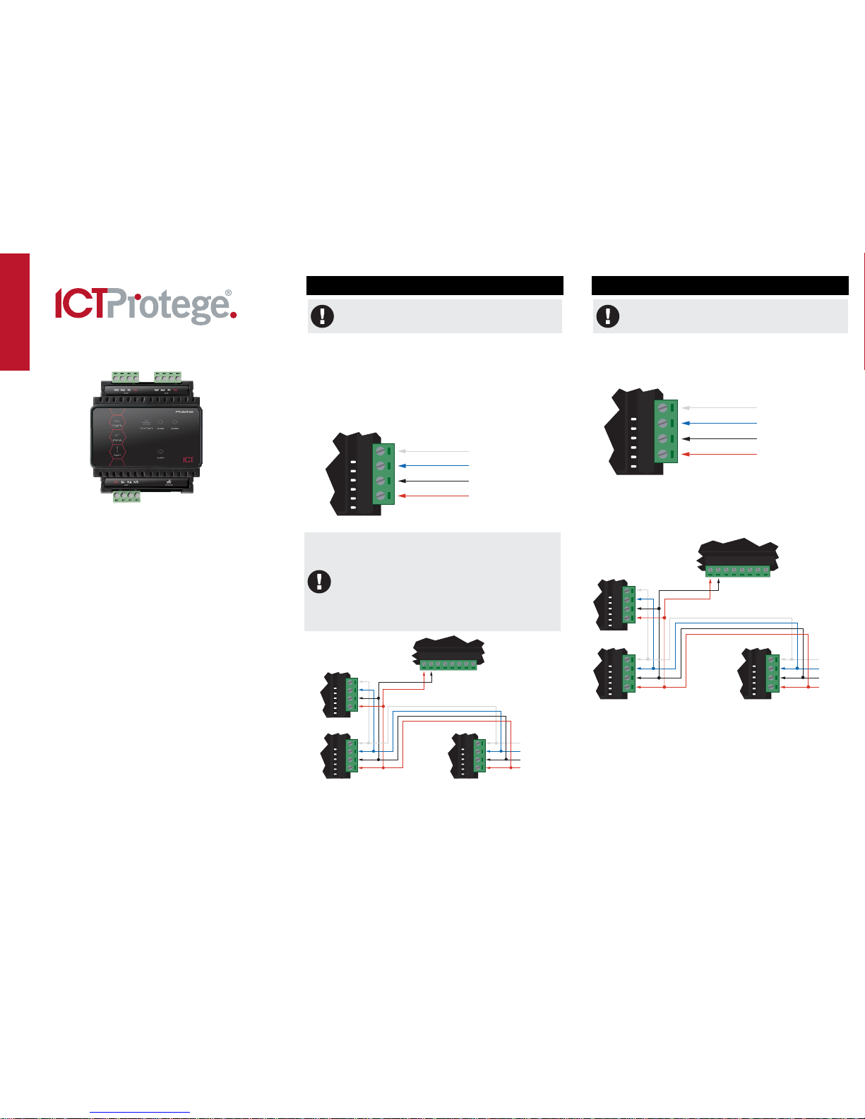
1. Power Supply
For devices using hardware revision 010, COM1 can only
be used for supplying power to the network repeater when
the module is connected via Ethernet.
The network repeater provides the connection of up to three
optically isolated RS-485 network stubs. To maintain proper
isolation, each connection requires a separate power supply.
Power to the network repeater is supplied by the N+ and Nterminals on the COM1 port and is also used for the on-board
electronics and the Ethernet connection.
It is important that the N+ module power is 12VDC supplied from an
independent battery backed power supply unit such as the
PRT-PSU-DIN capable of supplying the required voltage.
NAN+ N- NB
Network communications input
from the Protege Integrated
System Controller or previous
Protege module
Standard DC Power Connection
Warning:
The 12V N+ and N- DC power input must be supplied
from only ONE point. Connections from more than one
12V supply may cause failure or damage to the
PRT-MNR2-DIN module.
A 330 Ohm EOL (End of Line) resistor MUST be
inserted between the NA and NB terminals of the
module directly connected to the Module Network
Repeater.
End of Line Resistor
The COM2 and COM3 ports are powered separately and optically
isolated from each other.
2. Encrypted Module Network
For devices using hardware revision 010, you can only use
COM2 and COM3 to create module network spurs when the
network repeater is connected via Ethernet.
The network repeater incorporates encrypted RS-485
communications technology. The isolated communications interface
offers full galvanic isolation to prevent ground loop noise and cross
phase ground differential between network devices on the three
RS-485 ports.
NAN+ N- NB
Network communications input
from the Protege Integrated
System Controller or previous
Protege module
Standard Communication Connection
Always connect the NA and NB terminals of the network repeater to
the NA and NB terminals of the communication network. The N+
and N- must go to a 12V power supply source as shown in the
following diagram and connected at ONLY one +12V power source.
NAN+ N- NB
NAN+ N- NB
Next module
on network
PRT-MNR2-DIN
AUX power from module or
external power supply
NAN+ N- NB
V- Z1V+ Z2 Z3 C
Z4
C
12VDC OUT ZONE INPUT 1-4
Network Power Supplied by Network Module
NAN+ N- NB
NAN+ N- NB
Next module
on network
PRT-MNR2-DIN
AUX power from module or
external power supply
NAN+ N- NB
V- Z1V+ Z2 Z3 C
Z4
C
12VDC OUT ZONE INPUT 1-4
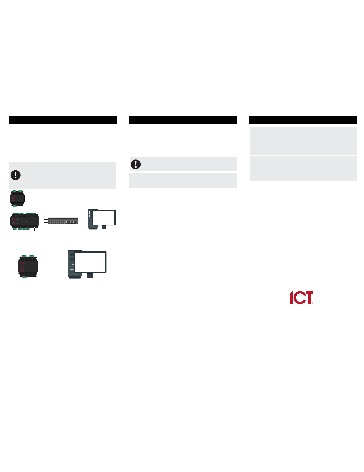
3. Ethernet 10/100 Network Connection
The network repeater can communicate with the controller via a
10/100 Ethernet connection using the encrypted UDP protocol, or
via the RS-485 module network using the COM1 port.
Ethernet communication is not enabled by default, and is configured
through the web interface.
When installing an Ethernet connection the network repeater should
be interfaced using a standard segment (<100M in length) and
should be connected to a suitable Ethernet hub or switch.
Installing the module network repeater on an active network
requires knowledge of the configuration and structure for
the network. Always consult the network or system
administrator and ask them to provide you with a fixed IP
address that can be assigned to the module network
repeater.
POWER
STATUS
FAULT
ETHERNET
1234
8567
MODEM
R1
READER
R2 RELAY 2
BELL
RELAY 1
ZONE
PRT-CTRL-DIN
BZL1
D1/NBD0/
NA Z8 V-Z7 Z6V-
Z5V-
V+
BZL1
D1/NBD0/
NA Z4 V-Z3 Z2V- Z1V- V+
N+
N-NA
NB
B+B-
NO
COM
NCNO
COMNC T1iR1i T1oR1o
ETHERNET 1MODEMRELAY 2RELAY 1
BELL
RS485 NETWORK
12VDC IN
READER 2 ZONE INPUT 5-8 12VDC OUT READER 1 ZONE INPUT 1-4 12VDC OUT
POWER
STATUS
FAULT
Ethernet 10/100 Switch Hub Connection
Temporary direct connections can be used for onsite programming
by using a standard Ethernet cable.
POWER
STATUS
FAULT
Ethernet 10/100 Direct Connection
4. Repeater Configuration
Configuration of the network repeater is carried out using the built in
web interface. To access the web interface, open an Internet
browser (such as Internet Explorer or Mozilla Firefox) and type the
IP address of the network repeater into the address bar.
The default IP address is 192.168.1.3 and the default operator login
is admin with the password admin. For security reasons, this
password should be changed before deployment.
When attempting to view the web page from a network that
uses a Proxy Server, ensure the browser connection
options are configured to recognize local addresses.
For more information on programming the network repeater through
the web interface, refer to the full installation guide available on the
ICT Website (http://www.ict.co).
5. Technical Specifications
Operating Voltage 12V DC
Operating Current 65mA (typical)
RS-485 3 isolated RS-485 communication interface ports
Ethernet 1 10/100Mbps Ethernet Communication Link
Dimensions (L x W x H) 78 x 90 x 60mm (3.07 x 3.54 x 2.36"")
Weight TBC
Operating Temperature 0˚-49˚C (32˚ - 122˚F)
Humidity 0%-93% non condensing, indoor use only (relative
humidity)
Storage -10˚- 85˚C (14˚ - 185˚F)
It is important that the unit is installed in a dry cool location that is not affected
by humidity. Do not locate the unit in air conditioning or a boiler room that can
exceed the temperature or humidity specifications.
Integrated Control Technology Limited
4 John Glenn Avenue, North Shore City 0632, Auckland, New Zealand
P.O. Box 302-340, North Harbour, Auckland, New Zealand
Phone: +64 (9) 476 7124
Fax: +64 (9) 476 7128
Email: support@incontrol.co.nz
www.ict.co
Designed and manufactured by Integrated Control Technology Limited.
© Copyright Integrated Control Technology Limited 2003-2015. All rights reserved.
227-5013-000 October 2016
 Loading...