

ICP PHX324000K00A1, PHX330000K00A1, PHX336000K00A1, PHX342000K00A1, PHX348000K00A1 Installation Guide
...Page 1
Installation Instructions
PHX3 Series
2 to 5 TON
PACKAGE HEAT PUMPS
TABLEOFCONTENTS
UNITDIMENSIONS ...................................... 2 - 3
SAFEINSTALLATIONREQUIREMENTS ......................... 4
LOCATINGTHE UNIT ....................................... 4
CLEARANCES ............................................ 4
INSTALLATION............................................ 5
GROUNDLEVELINSTALLATION .............................. 5
RooftopINSTALLATION..................................... 5
HOISTING................................................ 5
DOWNFLOWCONVERSION .................................. 5
CONDENSATEDRAIN....................................... 5
_ CLIS_IEDUS
ELECTRICALWIRING................................... 6
DUCTWORK.......................................... 7
FILTERS ............................................. 7
AIRFLOWADJUSTMENT ................................ 8
START-UPPROCEDURES ............................... 9
SEQUENCEOFOPERATION.............................. 9
MAINTENANCE ...................................... 10
RIGGING ........................................... 12
WIRINGDIAGRAMS ................................... 13
Printed in U.S.A.
CODE: PHX3
518 O1 1301 OO 1-4-O6
Page 2
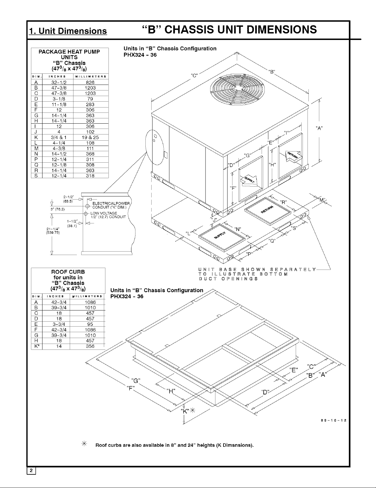
1. Unit Dimensions "B" CHASSIS UNIT DIMENSIONS
PACKAGE HEAT PUMP
DIM.
A
B
C
D
E
F
G
H
I
J
K
L
M
N
P
Q
R
S
UNITS PHX324 - 36
"B" Chassis
(473/8 x 473/8)
INCHES MILLOMETERS
47-3/8 1203
47-3/8 1203
3-1/8 79
32-1/2 826
11-1/8 283
12 306
14-1/4 383 .¢-..... _
14-1/4 363 _ _
12 308 "4 _ _1 "A"
4 102 "1''/
314_I19_28 f_ _ _I _J'"_
4-1/4 lO8 [ _ \ _ _ .;E'_
I1_% ;_1 ._ _ __ ....._ <. _.
12-1/4 311 y/_, /"J _/ _.,_'G_,_ T _ '/
12-1/8 308 y / _ 'U'_" JJ "H" -"_J J
14-1/4 363 / / '_ _ ' J_
12-1/4 318 i_-_ _ _
2-1/2" I
,_ 1/2" (12.7) CONDUIT \ _/" ,_, ,,, __- _ _ /_ "X_YfX
1-1/2" "d"
Units in "B" Chassis Configuration
_O _
ROOFCURB vo ILLUSTRATE IOTVO_I
for units in #UO7 OPENINGS
"B" Chassis
(473/8 X 473/8) Units in "B" Chassis ConfigurationF_.
DIM.
'NCHEI_ _ ......... 8 PHX324 -- 36 // _
A
42-3/4 1086 _ _x
B
39-3/4 1010 _ _
C
D
E
F
G
H
K*
18 457 _ _ _
18 457 j_ _
3-3/4 98 _ _ j_._
42-3/4 1086 _ _ _ _._
"F'_ 80=_o=I_
J< Roof curbs are also available in 8" and 24" heights (K Dimsnsions).
Page 3
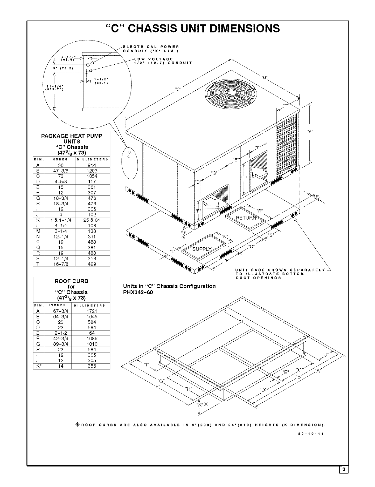
"C" CHASSIS UNIT DIMENSIONS
PACKAGE HEAT PUMP
UNITS
"C" Chassis
(473/8 x 73)
DIM INCHES MILLOMETER8
A 36 914
B 47-3/8 1203
C 73 1354
D 4-5/8 117
E 15 361
F 12 307
G 18-3/4 476
H 18-3/4 476
I 12 306
J 4 102
K 1 &1-1/4 25&31
L 4-1/4 108
M 5-1/4 133
N 12-1/4 311
P 19 483
Q 15 381
R 19 483
S 12-1/4 318
T 16-7/8 429
ROOF CURB
for
"C" Chassis
(473/8 x 73)
DIM INCHES MOLLIM_T_RS
A 67-3/4 1721
B 64-3/4 1645
C 23 584
D 23 584
E 2-1/2 64
F 42-3/4 1086
G 39-3/4 1010
H 23 584
I 12 305
J 12 305
K* 14 356
CONDUIT ('K" DIM.)
CAL POWER
VOLTAGE
_/2 = (12.7) CONDUIT
Units in "C" Chassis Configuration
PHX342-60
,,p,,
UNIT BASE SHOWN SEPARATELY
TO BLLUSTRATE BOTTOM
DUCT OPENINGS
"F\
=_ROOF CURBS ARE ALSO AVAILABLE IN 8"(203) AND 24"(fl10) HEIGHTS (K DIMENSION),
80-10-11
Page 4
2. SAFE INSTALLATION REQUIREMENTS
Installation and servicing of air-conditioning equipment can
be hazardous due to system pressure and electrical
components. Only trained and qualified personnel should
install, repair, or service air-conditioning equipment.
Untrained personnel can perform basic maintenance
functions of cleaning coils and filters. All other operations
should be performed by trained service personnel. When
working on air-conditioning equipment, observe
precautions inthe literature, tags, and labels attached to the
unit, and other safety precautions that may apply.
Follow all safety codes. Wear safety glasses and work
gloves. Use quenching cloth for unbrazing operations.
Have fire extinguisher available for all brazing operations.
FIRE AND ELECTRICAL SHOCK HAZARD
Improper installation, adjustment, alteration, service,
maintenance, or use can cause fire or an explosion
which could result in personal injury or unit damage.
Consult a qualified installer, service agency, or gas
supplier for information or assistance. The qualified
installer or agency must use only factory-authorized kits
or accessories when modifying this product.
FIRE, AND ELECTRICAL SHOCK HAZARD
Failure to follow this warning could result in personal
injury, death and/or property damage.
Before performing service or maintenance operations
on unit, turn off gas supply to unit. Then turn off unit main
power switch and install lockout tag. Electrical shock
could cause serious injury or death.
RecognizAe safety information. This is the safety-alert
symbol/.Vk,. When you see this symbol in instructions or
manuals, be alert to the potential for personal injury.
Understand the signal words DANGER, WARNING,
CAUTION, and NOTE. These words are used with the
safety-alert symbol. DANGER identifies the most serious
hazards which will result in serious injury or death.
WARNING signifies a hazard which could result in serious
injury or death. CAUTION is used to identify unsafe
practices which may result in minor personal injury or
product and property damage. NOTE is used to highlight
suggestions which will result in enhanced installation,
reliability, or operation.
FIRE, AND ELECTRICAL SHOCK HAZARD
Failure to carefully read and follow all instructions in this
manual could result in furnace malfunction, property
damage, personal injury and/or death.
Installation or repairs made by unqualified persons can
result in hazards to you and others. Installation MUST
conform with local building codes or, in the absence of
local codes, with the National Electrical Code
NFPA70-2005 or in Canada the CSA C.22.1 - Canadian
Electrical Code Part 1.
The information contained in this manual is intended for
use by a qualified service technician familiar with safety
procedures and equipped with the proper tools and test
instruments.
SAFETY CONSIDERATIONS
• Install this unit only in a location and position as specified
in section 3 of this manual.
•Always install unit to operate within the unit's intended ex-
ternal static pressure within the allowable range, as
specified in section 6. Refer to unit rating plate for the al-
lowable external static pressures.
•All connecting ductwork to the unit (supply and return)
must be sealed to the unit casing as specified insection 5.
•Check to see that filters are installed correctly and are the
proper type an size.
NOTE: It is the personal responsibility and obligation of the
customer to contact a qualified installer to ensure that the
installation is adequate and conforms to governing codes
and ordinances.
INTRODUCTION
The PHX3 unit is a fully self-contained, electric heat pump
unit designed for outdoor installation (See page 2 for unit
dimensions). All unit sizes have return and discharge
openings for both horizontal and downflow configurations,
and are factory-shipped with all downflow duct openings
covered.
3. LOCATING THE UNIT
ACCESS PANELS
See Figure 1 for a general view of unit and location of
access panels.
CLEARANCES
The location MUST allow for minimum clearances and
should not be adjacent to a patio or other area where the
unit's operating sound level might be objectionable. The
combustion air inlet openings MUST not be obstructed (see
NO TAG). In addition, local codes MUST be observed.
NOTE: Units with available filter racks (3-1/2 to 5 ton), need
a 26" minimum clearance at side of unit for removal of
filters. See chart below if unit is going to be placed near
combustible construction or materials.
While minimum clearances are acceptable for safety
reasons, they may not allow adequate air circulation around
the unit for proper operation in the cooling mode. Whenever
possible, it is desirable to allow additional clearance,
especially around the condenser inlet and discharge
openings.
141
Page 5

Do NOT install the unit in a location that will permit
discharged air from the condenser to recirculate to the
condenser inlet,
UNIT DAMAGE HAZARD
Failure to follow this caution may result in shorten life
of unit components.
Do NOT operate unit in a corrosive atmosphere
containing chlorine, fluorine, or any other corrosive
chemicals.
Minimum Clearances to Combustible Construction
DuctSide .................. 2" (6" on largechassis models)
Condenser Inlet .................................... 30"
BlowerService (Side) ............................... 30"
Control Service Side
(Front Combustion Air Inlet) .............. 30"
Clearance between 3 Ft. Overhang
and Top of Unit ......................... 30"
Combustible Base
(Woodor ClassA, B or C
roof covering material) ..................... 0"
Minlmomc,earoooosoodAooesspano,sCho si Shownl
Biower Compartment Panel
B Chassis - 2"
C Chassis - 6"
- Platform must be high enough to allow for proper
condensate trap installation and drainage. See Figure
2 and associated text for more information about
condensate drainage.
Rooftop Installation
Rooftop platform requirements:
- The unit MUST be situated to provide safe access for
servicing.
- The existing roof structure MUST be adequate to
support the weight of the unit or the roof MUST be
reinforced.
Check the weight of the unit in relation to the roof
structure and local building codes or ordinances and
reinforce roof structu reif necessary. See page 12 of this
manual for unit weights.
- Support for the unit MUST be level and strong enough
to carry unit weight. The support may consist of a
platform or a combination of platform and roof beams or
curb.
- See Hoisting section for hoisting instructions.
HOISTING
NOTE: All access panels MUST be secured in place before
hoisting.
The unit should be hoisted with two lifting slings. Attach the
slings to rigging shackles that have been hooked through
holes in the base rail.
Two spreader bars MUST be placed on top of the unit to
protect the unit from damage from the pressure exerted by
the slings, Make sure that all equipment is adequate to
handle the weight ofthe unit and that the slings will not allow
the unit to shift,
Refer to NO TAG on page 12 of this manual for illustrated
rigging instructions and weight chart,
DOWNFLOW CONVERSION
80"
80-00-01
Control Panet
INSTALLATION
NOTICE
Unit will NOT operate properly unless it is installed lev-
el front to rear and side to side. The slope MUST NOT be
greater than /8 perfoot (10mm per meter). For side to
1 ,
side leveling, the drain side MUST always be lower.
Ground Level Installation
Ground level platform requirements:
- The unit MUST be situated to provide safe access for
servicing.
Platform may be made of either concrete or pressure
treated wood and MUST be level and strong enough to
support unit weight.
Position platform separate from building foundation.
Install in well-drained area, with top surface of platform
above grade level.
NOTE: In downflow applications with roof curbs or jack
stands, the center rail under the unit must be removed. The
center rail is attached to the base rail with screws.
These units are adaptable to downflow use, To convert to
downflow use, follow these steps:
1. Remove the blockoff plates found in the return air
compartment and the supply air compartment.
NOTE: Blockoff plate in the supply air compartment only
contains one screw. If reinstalling plate, back part of plate
MUST fit into mating dimples on flange. To reinstall, slant
plate into dimples, then put plate into position and fasten
with screw.
2. Install the removed plates on the horizontal return and
supply air openings.
3, Install roof curb on the building. Be sure to follow all
directions included with curb and all applicable building
codes in your installation.
Condensate Drain
The condensate drain outlet is a 3/4'' (19.1 mm) female PVC
connection located at the bottom on the left hand side (see
Figure 2),
151
Page 6

The circulating blower creates a negative pressure on the
condensate drain line that can prevent the condensate from
draining properly. To combat this negative pressure, a field
supplied condensate trap that will allow a standing column
of water of at least 2" (50.8mm) MUST be installed. Top of
outlet from trap MUST be at least 1" (25.4mm) below top of
outlet from unit. Install the trap as near to the unit as
possible for proper drainage.
A 3/4" (19.1 mm) drain line MUST be installed if required by
local codes or if location of unit requires it. Run the drain line
to an open drain or other suitable disposal point.
FIGURE 2 I Condensate Drain Information*
3/4" (19,1mm)
Threaded Female
PVC Fitting
b
25-1/2 ("B" Chassis)
32-1/4 ("C" Chassis)
(25.4mm)
/
2" (50.8mm)
* Condensate trap MUST be installed.
4. ELECTRICAL WIRING
ELECTRICAL SHOCK HAZARD.
Failure to follow this warning could result in personal
injury, death and/or property damage.
The unit cabinet must have an uninterrupted,
unbroken electrical ground to minimize the possibility
of serious injury if an electrical fault should occur.
This ground may consist of an electrical wire
connected to the unit ground lug in the control
compartment, or conduit approved for electrical
ground when installed in accordance with National
Electric Code (NEC) NFPA 70, National Fuel Gas Code
NFPA 54-2005/ANSI Z223.1-2005 and local electrical
codes. In Canada, follow Canadian Electrical Code
CSA (Canadian Standards Association) C22.1 and
local electrical codes.
REDUCED EQUIPMENT LIFE HAZARD
Failure to follow these precautions could result in
damage to the unit being installed.
1)Make all electricalconnections inaccordance with
NationalElectriccode (NEC)NFPa70 andlocalelectrical
codes governing such wiring. In Canada, all electrical
connections must be inaccordance with CSA standard
C22.1, Canadian Electrical Code Part 1, and applicable
local codes. Refer to unit wiring diagram.
2) Use only copper conductor for connections
betweenfield-supplied electricaldisconnectswitchand
unit. DO NOT USEALUMINUM WIRE.
3) Be sure that high-voltage power to unit is within
operating voltage range indicated on unit rating plate.
4) Donot damageinternalcomponentswhendrilling
through any panel to mount electrical hardware,
conduit, etc. Consult local power company for
correction of improper voltage and/or phase imbalance.
Disconnect Switch
The unit must have separate electrical service with a
field-supplied, waterproof, disconnect switch mounted at,
orwithin sight from, the unit. Refer tothe unit rating plate for
maximum fuse/circuit breaker size and minimum circuit
amps (ampacity) for wire sizing.
Ground Connections
Do NOT complete line voltage connections until unit is
permanently grounded. All linevoltage connections and the
ground connection MUST be made with copper wire.
A ground lug is installed in the control box area for the
ground connection. Use a copper conductor of the
appropriate size from the unit to a grounded connection in
the electrical service panel or a properly driven and
electrically grounded ground rod. See warning above.
Line Voltage Wiring - (Wiring Diagrams page 13)
Connections for line voltage are made in the unit control box
area. Refer to wiring diagram located on the Burner Access
panel. For access, remove the burner access panel.
1. Run the high voltage (L1, L2) and ground leads into the
control box.
2. Connect ground lead to chassis ground connection.
3. Connect L1 to pressure lug connection 11 of the
compressor contactor.
4. Connect L2 to pressure lug connection 23 of the
compressor contactor.
Thermostat / Low Voltage Wiring
Location of the thermostat has an important effect on home
comfort. FOLLOW THE THERMOSTAT INSTRUCTION
MANUAL FOR CORRECT LOCATION, MOUNTING, AND
WIRING.
All Models:
A two-stage thermostat is required for proper operation.
Thermostat should have the following terminals: "R',
"W/W1", "Y1 ", "O", and "G'. Some electronic thermostats
use low voltage from the unit for power for temperature
161
Page 7

display and programming. These electronic thermostats
will have a "C" terminal. The outdoor unit has color-coded
wires for easy connection. Using wire nuts, follow Figure 3
for proper connections:
FIGURE 3 2 to 5 Ton Thermostat Connections
fG_=
\-S
fO\,l .................................... /
'\ J........... _I
_\. j
Thermostat and subbase Unit Control Power
THERMOSTAT HEAT ANTICIPATOR
Some thermostats have an adjustable heat anticipator. The
heat anticipator prevents temperature overshoot in heating
mode. If the heat doesn't turn off until the set point
temperature on the thermostat is exceeded, then the
anticipator setting is too low. If the heat turns off before the
thermostat reaches the set point temperature on the
thermostat, then the anticipator setting is too high. Follow
the thermostat instruction manual for proper adjustment of
the heat anticipator.
Final Electrical Check
1, Make afinal wiring check to be sure system is correctly
wired. Inspect field installed wiring and the routing to
ensure that rubbing or chafing due to vibration will not
occur.
NOTE: Wiring MUST be installed so it is protected from
possible mechanical damage.
5. DUCTWORK
Ductwork Sizing
The maximum recommended velocity in trunk ducts is 1000
feet per minute. The maximum recommended velocity in
branch ducts is 800 feet per minute.
Filter Sizes
Ductwork sizing affects the discharge temperature, airflow
velocity, and efficiency of the system. Be sure to properly
size ductwork to the capacity of the unit and to the airflow
requirements of the conditioned space. Failure to properly
size ductwork can result in inadequate airflow and poor
efficiency. Undersized ductwork may result in tripped limit
controls and premature failure of compressors, motors and
other components.
Ductwork Insulation
Ductwork installed outdoors must have a minimum 2" thick
fiberglass "wrap" insulation and a weatherproof vapor
barrier installed around it. The insulation and vapor barrier
must be protected against potential damage. Caulking,
flashing, and other means of providing a permanent
weather seal must be used.
Ductwork Connections
The use of flexible, non-combustible connectors between
main trunk ducts and supply and return air plenums is
permitted. If flexible connectors are used, they should be
protected from potential mechanical damage such as
punctures and tears.
NOTE: When connecting the supply and return plenums to
the unit, make sure that the plenums are sealed against the
side casing of the unit and do not interfere with removal of
the top of the unit.
FILTERS
All return air MUST pass through a filter before entering the
unit. An electronic air cleaner, optional filter racks, or other
accessible filter arrangement must be installed inthe return
air ductwork. Minimum recommended filter sizes are listed
in FIGURE 4 and are based on maximum face velocities of
300 ft!min for disposable filters and 500 ft/min for washable
(high velocity) filters.
REDUCED EQUIPMENT LIFE HAZARD
Failure to follow this caution may result in improper
unit operation.
Do not operate the unit without a filter,
PHX3 Filter Data
Model
PHX324000K00A1
PHX330000K00A1
PHX336000K00A1
PHX342000K00A1
PHX348000K00A1
PHX360000K00A1
Disposable Filters
Nominal Size (Qty
xwxd)
1 x 20" x 20"
1 x 20" x 24"
2x 15"x20"
2x 18"x20"
2 x20" x20"
2 x20" x24"
Minimum Area (sc
inches)
384
480
576
672
768
960
Wasabte Filters
Nominal Size (Qty
xwxd)
1 x 10" x 20"
1 x 12" x 20"
1 x 15" x20"
1 x 18" x20"
1 x 20" x 20"
1 x 20" x 24"
Minimum Area (sq
inches)
192
24O
288
336
384
48O
171
Page 8

6. AIRFLOW ADJUSTMENT
CIRCULATING AIR BLOWER SPEEDS
ModelNumber PHX324 PHX330 PHX336
Torque(ox Ft.} 596 1098 1553 18.04 29.02 11.92 1302 18.04 23.06 29.02 1859 24.00 34.35 52.94
SpeedTap 1 2 3 4 5 1 2 3 4 5 1 2 3 4
AirDeliveryin CFM 04 252 564 768 858 I170 618 568 857 1017 I1C4 755 913 1179 I477
@VaryingExtemal 05 219 529 738 811 I199 584 530 828 992 I138 694 871 1150 I415
StaticPressure 08 188 481 584 775 I100 524 582 785 954 II12 651 841 1117 I354
(in.w c.} 07 431 550 733 I063 494 542 750 924 I077 598 793 1086 1287
ModelNumber PHX342 PHX349 PHX360
Torque(ox Ft.) 19.06 2306 34.12 41.98 44.00 26.99 3200 51.14 59.92 8000 30!2 3106 55.84 73.10 8000
SpeedTap 1 2 3 4 5 1 2 3 4 5 1 2 3 4 5
AirDeliveryin CFM 04 797 881 1179 1374 I463 1027 1187 1578 1732 I942 1189 1231 1735 I987 2039
@VaryingExternal 05 749 838 1138 1338 I423 983 1126 1544 1696 I878 1117 1197 1702 I935 1974
StaticPressure 08 702 789 1103 1298 I389 927 1077 1507 1661 I809 1073 1144 1567 I878 1905
(in.w c.} 07 642 731 1080 1263 I353 881 1028 1470 1621 I723 1028 1105 1629 I811 1827
Notes A9 Delivery@]isledexternalstaticpr_sslearetakenat230Vo0swh Dlycoil nofit_r and applovedb_aler
01 001 /1I 809 901 I201 /b4 /89 959 1100 I250 9(0 1026 12/0 1030
O2 478 655 842 914 I218 708 747 923 1080 I227 841 994 1242 I588
03 334 623 809 883 I194 671 714 894 1048 I201 794 949 1209 I526
O8 392 599 897 988 443 495 712 881 I027 543 735 1045 I216
09 334 569 858 871 382 460 861 838 934 499 583 998 I145
I 305 523 518 745 342 403 530 755 809 464 538 948 1070
O1 973 1028 1302 1481 I569 1173 1304 1680 1831 2103 1300 1388 1839 2091 2188
02 900 969 1280 1448 I537 1127 1256 1650 1797 2051 1253 1321 1807 2056 2140
03 853 924 1219 1412 I500 1085 1216 1614 1763 2001 1214 1283 1772 2023 2096
O8 581 680 1015 1228 I317 821 979 1427 1559 I632 975 1038 1590 I729 1745
09 529 617 963 1188 I278 784 921 1373 1446 I526 928 969 1535 1640 1642
I 476 582 923 1143 I298 710 875 1289 1339 I388 882 913 1460 1536 1537
Forwetcodadd 05in wc b Sta0cPlessuremeasur_mentNotefor208Vo0sappicatlons,reduceaflowby15%
BlowerSpeedTapSe
Models LowCapacityAirflow RatedAirflow
PHX324 SpeedTap1 SpeedTap3
PHX330 SpeedTap1 SpeedTap4
PHX336 SpeedTap1 SpeedTap3
PHX342 SpeedTap1 SpeedTap4
PHX348 SpeedTap1 SpeedTap3
PHX360 SpeedTap2 SpeedTap
iin_ls
HighCapacityAirflow
SpeedTap5
SpeedTap5
SpeedTap5
SpeedTap5
SpeedTap5
SpeedTap5
Airflow Adjustment (cont,)
Verify that the proper blower speeds for heating and cooling
are selected on the blower motor by removing the blower
access panel and inspecting the blower motor. The motor
has 5 speeds numbered "1", "2", "3", "4" and "5". The wires
for the speed selection are as follows:
Red _ Heating
Black _ High Stage Cooling
Violet =1_ Low Stage Cooling (4 ton only)
Using the same speed for Heating and Cooling.
If the same speed is required for heating and low stage
cooling, the following procedure must be used:
1. Set Red wire on proper speed selection on blower
motor.
2. Remove Violet wire from "LO" on Blower Interface
Board. Tape end of Violet lead using electrical tape.
3. Jumper the Red wire to both the "Heat" terminal and the
"LO" terminal on the Blower Interface Board.
181
Page 9

7. START-UP PROCEDURES
CHECK BEFORE STARTING
1. Check that the blower motor speed terminal block is
running the correct heating and cooling speeds.
2. Check to see that clean, properly sized air filters are
installed.
3. Replace all service access panels.
Check the unit's operation as outlined in the following
instructions. If any unusual sparking, odors or unusual
noises are encountered, shut off electric power
immediately. Recheck for wiring errors, or obstructions in or
near blower motors.
1. Set thermostat Heat-Cool selector to OFE
2. Set thermostat fan switch to AUTO.
3. Turn electric power ON. Nothing should start running.
4. Set thermostat fan switch to ON,
5. Reset thermostat fan switch to AUTO.
8. SEQUENCE OF OPERATION
ELECTRICAL SHOCK HAZARD.
Failure to follow this warning could result in personal
injury, death and/or property damage.
Turn off electric power supply at disconnect switch or
service panel before removing any access or service
panel from unit.
Cooling Operation (PHX324 - 60)
These units utilize a 2 stage indoor thermostat. With a first
stage call for cooling (Y1), the indoor fan (low stage)
energizes immediately where as the contactor energizes
after a 5 minute time delay (incase of an initial start up)
starting the compressor (low stage) and the outdoor fan
motor. If the low stage operation cannot satisfy the cooling
demand, the second stage cooling (Y2) energizes
switching the compressor into high stage cooling through
energizing an internal solenoid valve inside the scroll
compressor and switching the indoor fan into high stage.
When second stage cooling is satisfied, Y2 de-energizes
switching the compressor and the indoor fan into low stage
cooling. When the low stage cooling demand is met, Y1
de-energizes shutting the compressor, indoor fan and the
outdoor fan.
Heating Operation (PHX324 - 60)
With a first stage call for heating (Y1), the indoor fan (low
stage) energizes immediately whereas the contactor
energizes after a 5 minute time delay (incase of an initial
start up) starting the compressor (low stage) and the
outdoor fan motor. If the low stage operation cannot satisfy
the heating demand, the second stage heating (Y2)
energizes switching the compressor into high stage heating
through energizing an internal solenoid valve inside the
scroll compressor and switching the indoor fan into high
stage. The auxiliary or back up heat is controlled by a third
stage (W2). If the demand is not met, W3 is energized
incase of staged heating. When heating demand is
satisfied, W3, W2 and Y2 sequentially de-energize
switching the compressor and the indoor fan into low stage
heating. When the low stage heating demand is met, Y1
de-energizes shutting the compressor, indoor fan and the
outdoor fan.
Scroll Recycle Delay timer
The defrost board is equipped with a recycle delay timer
which will delay the start of the compressor for 5 minutes in
the event of a power interruption. This sequences power
throughout the system and prevents possible reverse
rotation of the scroll compressor. The output of the timer
controls the compressor contactor via a normally open
contact of K3 (T2). The timer starts the delay cycle whenthe
compressor is turned off by removal of "Y." If application of
"Y" occurs before the timer has expired, the compressor
contactor will not be energized until the timer has expired.
CONTINUOUS FAN OPERATION
With the continuous Indoor fan option selected on the
thermostat, G is continuously energized. Incase of 024 -
042 units, the selected airflow setting is provided. Incase of
048 and 060 units, the system runs low stage (Y1) airflow for
continuous fan operation.
Defrost Mode
On a call for defrost:
When the defrost sensor closes in the heating mode, there
isa 30, 60, 90 or 120 minute delay before the defrost mode
begins. This delay is selected by the position of the
dipswitches on the defrost board. Defrost interval timing
can be configured by selection switch 1 and 2 on the
dipswitch per the following table: See Figure 6.
Switch 1
ON
OFF
OFF
ON
NOTES:
Switch 2 Time
OFF 30 Minutes
ON 60 Minutes
OFF 90 Minutes
ON 120 Minutes
1. The backup defrost terminate time is fixed at 10
minutes.
2. The compressor recycle delay timer is 5 minutes.
3, The power interrupt response is minimum 17 msec, to
maximum 35 msec.
4. Quite shift compressor recycle delay is 30 seconds.
In normal defrost mode, the following sequence will occur
after the set delay:
1. Condenser fan off.
2,
Reversing valve energized to cooling and auxiliary
electric heat (W2) is energized.
3.
After defrost sensor opens or a maximum of 10
minutes; the condenser fan is energized (after 20
seconds) and the reversing valve is de-energized to
the heat mode. Electric strip heat is also de-energized
(after 15 seconds) except as required by the
thermostat,
191
Page 10

4. Should the system indoor thermostat be satisfied
during the defrost cycle, the control will de-energize the
reversing valve and auxiliary heat outputs and "hold"
the defrost timer until the next call for heat, at which time
the defrost cycle will be completed.
Service testing: the pins marked "speed up" when
momentarilyshorted together (for 5seconds) and released,
will defeat the 5 minutes recycle delay timer and allow the
compressor contactor to be immediately energized, thus
forcing adefrost cycle. Termination of this forced mode will
be by the defrost thermostat or the 10 minute backup timer,
provided the defrost thermostat was closed when the
defrost was "forces." If the defrost thermostat was not
closed, at the time of the "forced defrost," the defrost mode
will remain for 30 seconds and then terminate.
FIGURE 6 Defrost Board & Dip Switches
Defrost Board
Dip Switch
9. MAINTENANCE
MONTHLY MAINTENANCE AND INSPECTION
CHECKS
Air Filters
REDUCED EQUIPMENT LIFE HAZARD
Failure to follow this cautions may result in damage to
the unit being installed.
Do not operate the unit without a filter.
Inspect filters at least monthly and replace or clean as
required. Washable filters may be cleaned by soaking in
mild detergent and rinsing with cold water. Replace filters
with the arrows on the side pointing in the direction of air
flow. Dirty filters are the most common cause of inadequate
heating or cooling performance, and of compressor
failures.
COOLING SEASON CHECKS (MONTHLY)
Condenser Coil
Keep the condenser inlet and outlet area clean and free of
leaves, grass clippings or other debris. Grass should be
kept short in front of the condenser inlet. Shrubbery MUST
be trimmed back so it is no closer than 30 inches to unit.
Condensate Drain
Check for condensate drainage. Clean as required.
ANNUAL MAINTENANCE AND INSPECTION
ELECTRICAL SHOCK HAZARD.
Failure to follow this warning could result in personal
injury, death and/or property damage.
Turn off electric power supply at disconnect switch or
service panel before removing any access or service
panel from unit.
The annual inspection should include cleaning as required
to ensure efficient operation of the unit. To simplify access,
remove all access panels and the top from the unit if
possible.
Condenser Fan Motor
Note: The condenser fan motor is permanently lubricated.
No further lubrication is required. Do not attempt to
lubricate the condenser fan motor.
Clean the surrounding area and the condenser and
evaporator coils. Use caution to avoid damage to coil fins.
BLOWER MOTOR ACCESS
Refer to Figure 1 for blower motor access panel and
compartment.
1. Remove the blower access panel
2. Remove the three screws securing the blower motor
housing. If unit has a support bracket, remove the two
screws securing the bracket.
3. Remove the two red wires attached to the limit
switchand remove the limit switch.
Motor removal and replacement
This method is required to replace or repair blower wheel,
blower housing, or any unreachable components behind
blower assembly.
1. Remove all screws around rim of unit top, (except
screws which are inaccessible because of proximity to
structure).
2. Raise unit top at corner of unit closest to blower at least
2" and place asturdy brace at least 2" thick between top
and unit corner. A 2X4 piece of wood is ideal for this.
3. Disconnect all wires from housing and slide housing out
of unit. Reverse this process to reinstall.
Circulating Air Blower
Visually inspect the blower wheel for accumulations of dirt
or lint. Clean the compartment and the blower wheel. If
accumulation is excessive on blower wheel, or does not
easily remove, it will be necessary to remove the blower
assembly.
Note: The blower motor is permanently lubricated. No
further lubrication is required. Do not attempt to lubricate
the blower motor.
Page 11

FIGURE 7 Control Box
Defrost
Board
Motor
Board
o
Transformer
Contactor
Run Capacitor
Capacitor Strap
Ill
Page 12

E
R GG NG INSTRUCTIONS __
fAiLURETOfOLLOW-_-SE_.STRUC-r_O_S
//_ WA_\ NO CAN RESULT IN PROPERTY DAMAGE,
BoD,_,_u_R_oRDEAT_
.o
:D
C:
m
QO
- ALL PANELS MUST BE IN PLACE WHEN RIGGING AND LIFTING.
- HOOK RIGGING SHACKLES THROUGH HOLES IN BASE RAIL, AS SHOWN IN DETAIL-A.
- USE SPREADER BARS, WHEN RIGGING, TO PREVENT UNIT DAMAGE.
- BE SURE RIGGING AND SHACKLES ARE SUFFICIENT TO HANDLE WEIGHT LISTED BELOW.
DETAIL-A
DER BARS
-¢
HEIGHT
_OR _
LENGTH WIDTH
tQ
t_
f-
0
m.
o
:3
Cabinet
Small
Large
Max. Length Max. Width
IN MM IN MM
52 1219 48 1219
73 1854 48 1219
Max. Height
IN MM
38 965
38 965
Max. Weight
LB KG
500 227
900 409
Page 13

11. Wiring Diagrams
2 to 5 Ton Wiring Diagram
SO Loading...