

Page 1
Installation Instructions
PHM3 SERIES
PACKAGE HEAT PUMPS
TABLEOFCONTENTS
SAFETYLABELINGANDSIGNALWORDS ....................... 2
UNITDIMENSIONS......................................... 3
SAFEINSTALLATIONREQUIREMENTS ......................... 3
LOCATINGTHE UNIT ....................................... 3
CLEARANCES ............................................ 4
INSTALLATION............................................ 4
INSTALLINGDUCTCOLLARS................................. 4
CONDENSATEDRAIN....................................... 5
UNITELECTRICALWIRING .................................. 5
LINEVOLTAGE............................................ 5
CONVERTING230VTO208V ................................. 6
LOWVOLTAGEWIRING ..................................... 6
THERMOSTATCONNECTIONS................................ 6
FINALELECTRICALCHECK.................................. 6
CONTROLBOXCONFIGURATIONANDWIRING ................... 7
WIRINGDIAGRAMS ........................................ 8
RAINSHIELDINSTALLATION................................ 10
AIR DISTRIBUTIONSYSTEM................................. 10
DUCTWORK............................................. 10
FILTERS................................................ 10
UNITELECTRICALWIRING ................................. 10
START-UP PROCEDURES.................................. 1!
SPEEDTAPS ............................................ 1!
CHECKBEFORESTARTING................................. 1!
DEFROSTINTERVAL ...................................... 12
SEQUENCEOFOPERATION................................. 13
OPERATION............................................. 14
LISTED
Printed in U.S.A. 11/8/05 427 O1 1101 OO
Page 2
1. Safety Labelinq and Siqnal Words
Danger, Warning and Caution
The signal words DANGER, WARNING and CAUTION are
used to identify levels of hazard seriousness. The signal
word DANGER is only used on product labels to signify an
immediate hazard. The signal words WARNING and
CAUTION will be used on product labels and throughout
this manual and other manuals that may apply to the
product.
Signal Words
DANGER - Immediate hazards which WILL result in
severe personal injury or death.
WARNING - Hazards or unsafe practices which COULD
result in severe personal injury or death.
CAUTION - Hazards or unsafe practices which MAY result
in minor personal injury or product or property damage,
Signal Words in Manuals
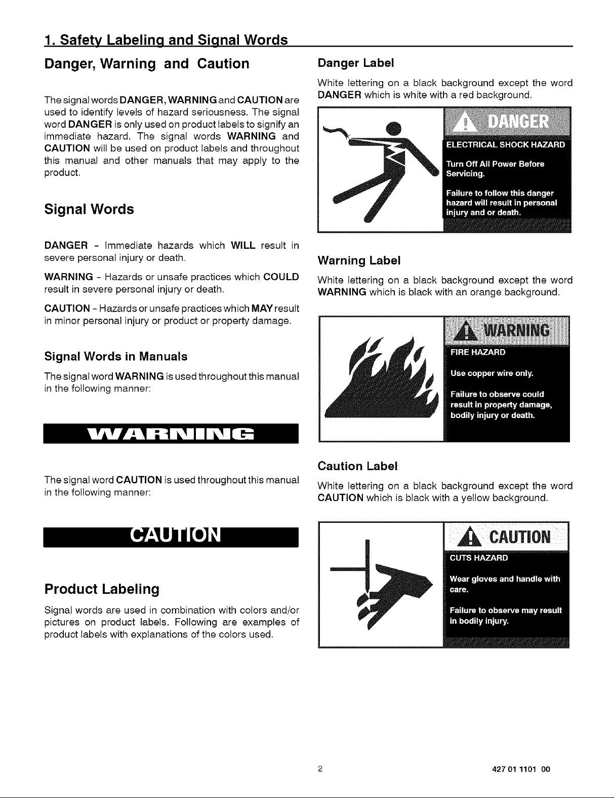
Danger Label
White lettering on a black background except the word
DANGER which is white with a red background.
Warning Label
White lettering on a black background except the word
WARNING which is black with an orange background,
The signal word WARNING is used throughout this manual
in the following manner:
The signal word CAUTION is used throughout this manual
in the following manner:
Product Labeling
Signal words are used in combination with colors and/or
pictures on product labels. Following are examples of
product labels with explanations of the colors used,
Caution Label
White lettering on a black background except the word
CAUTION which is black with a yellow background,
2 427 01 1101 00
Page 3
2. Dimensions
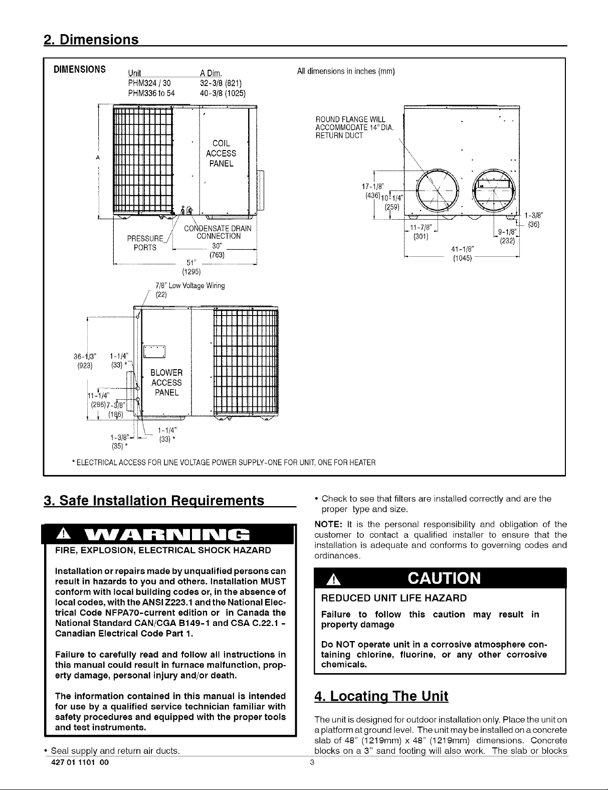
DIMENSIONS
36-1/3" 1-1/4"
(923)
Unit
PHM324 / 30
PHM336 to 54
IIIIII I Iil I I
RlllllllilII
RIIIIIIIilII
BIIIIIIIilII
_IIIIIII'III
RIIIIIIIIII
RIIIIIII,III
_lllllllilII
_lllllllilII
lllllllllilII
,.,,,,,,.,, _.
PRESSURE!
PORTS L_
(1295)
7/8"LowVoltageWiring
/ (22)
ADim.
32-3/8 (821)
40-3/8 (1025)
COIL
ACCESS
PANEL
CONNECTION
3O"
(763)
51"
Alldimensionsin inches(mm)
ROUNDFLANGEWILL
ACCOMMODATE14"DIA.
RETURNDUCT
1-3/8"
(36)
(301) (232)
41-1/8"
(lO45)
1-1/4"
(35)*
*ELECTRICALACCESSFOR UNEVOLTAGEPOWERSUPPLY-ONEFORUNIT,ONEFORHEATER
(33)*
3. Safe Installation Requirements
FIRE, EXPLOSION, ELECTRICAL SHOCK HAZARD
Installation or repairs made by unqualified persons can
result in hazards to you and others. Installation MUST
conform with local building codes or, in the absence of
local codes, with the ANSI Z223.1 and the National Elec-
trical Code NFPA70-current edition or in Canada the
National Standard CAN/CGA B149-1 and CSA C.22.1 -
Canadian Electrical Code Part 1.
Failure to carefully read and follow all instructions in
this manual could result in furnace malfunction, prop-
erty damage, personal injury and/or death.
The information contained in this manual is intended
for use by a qualified service technician familiar with
safety procedures and equipped with the proper tools
and test instruments.
• Seal supply and return air ducts.
42701 1101 oo
3
• Check to see that filters are installed correctly and are the
proper type and size.
NOTE: It is the personal responsibility and obligation of the
customer to contact a qualified installer to ensure that the
installation is adequate and conforms to governing codes and
ordinances.
REDUCED UNIT LIFE HAZARD
Failure to follow this caution may result in
property damage
Do NOT operate unit in a corrosive atmosphere con-
taining chlorine, fluorine, or any other corrosive
chemicals.
4. Locating The Unit
The unit is designed for outdoor installation only. Place the unit on
a platform at ground level. The unit may be installed on a concrete
slab of 48" (1219mm) x 48" (1219mm) dimensions. Concrete
blocks on a 3" sand footing will also work. The slab or blocks
Page 4
SHOULD NOT be in contact with any part of the structure. Check Installation
local codes covering zoning, noise, platforms, etc..
Avoid locating next to fresh air intakes, vent or bedroom windows.
Noise may carry into the openings and disturb people inside.
Avoid installations under roof overhangs without guttering. Water
draining from the roof onto the unit could produce excessive
noise, and may cause ice to build up on coil or fan.
Placement of the unit should be in a well drained area or the unit
MUST be supported high enough so runoff will not enter the unit.
Do not locate unit where heat, lint or exhaust fumes wil! be
discharged on unit (as from dryer vents.)
Clearances
The unit must be installed with a slope no greater than 1/8"
per foot (10mm per meter). For side to side leveling, the
condensate drain side side MUST always be lower.
The unit MUST be situated in such a way as to provide safe
access for servicing.
The platform may be made of either concrete or pressure
treated wood and MUST be level and strong enough to
support the unit's weight.
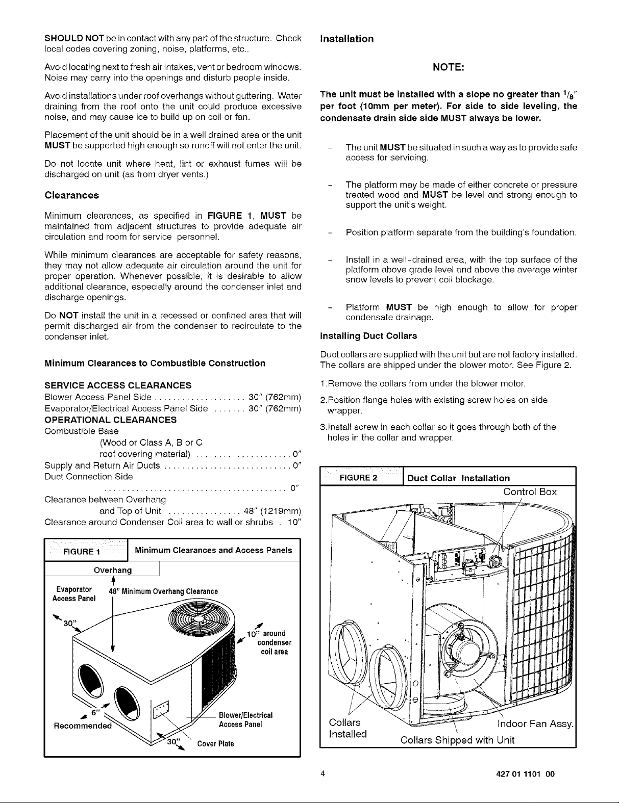
Minimum clearances, as specified in FIGURE 1, MUST be
maintained from adjacent structures to provide adequate air
circulation and room for service personnel.
Position platform separate from the building's foundation.
NOTE:
While minimum clearances are acceptable for safety reasons,
they may not allow adequate air circulation around the unit for
proper operation. Whenever possible, it is desirable to allow
additional clearance, especially around the condenser inlet and
discharge openings.
Do NOT install the unit in a recessed or confined area that will
permit discharged air from the condenser to recirculate to the
condenser inlet.
Minimum Clearances to Combustible Construction
SERVICE ACCESS CLEARANCES
Blower Access Panel Side .................... 30" (762mm)
Evaporator/Electrical Access Panel Side ....... 30" (762mm)
OPERATIONAL CLEARANCES
Combustible Base
(Wood or Class A, B or C
roof covering material) ..................... 0"
Supply and Return Air Ducts ............................ 0"
Duct Connection Side
........................................ 0 sl
Clearance between Overhang
and Top of Unit ................ 48" (1219mm)
Clearance around Condenser Coil area to wall or shrubs . 10"
FIGURE i Minimum Clearances and Access Panels
install in a well-drained area, with the top surface of the
platform above grade level and above the average winter
snow levels to prevent coil blockage.
Platform MUST be high enough to allow for proper
condensate drainage.
Installing Duct Collars
Duct collars are supplied with the unit but are not factory installed.
The collars are shipped under the blower motor. See Figure 2.
1.Remove the collars from under the blower motor.
2.Position flange holes with existing screw holes on side
wrapper.
3.Install screw in each collar so it goes through both of the
holes in the collar and wrapper.
FIGURE2 I Duct Collar Installation
Control Box
Overhang
Evaporator 48" MinimumOverhangClearance
AccessPanel
CoverPlate
10" around
f condenser
coilarea
BlowedElectrical
AccessPanel
Collars
Indoor Fan Assy.
Installed
Collars Shipped with Unit
4 427 01 1101 00
Page 5
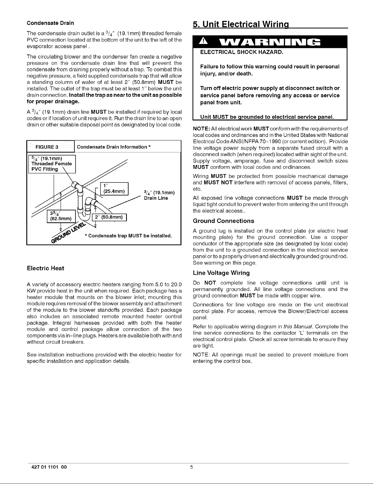
Condensate Drain
The condensate drain outlet is a 3/4" (19.1 mm) threaded female
PVC connection located at the bottom of the unit to the left of the
evaporator access panel.
The circulating blower and the condenser fan create a negative
pressure on the condensate drain line that wil! prevent the
condensate from draining properly without a trap. To combat this
negative pressure, a field supplied condensate trap that will allow
a standing column of water of at least 2" (50.Smm) MUST be
installed. The outlet of the trap must be at least 1" below the unit
drain connection. Install the trap as near to the unit as possible
for proper drainage.
A 3/4" (19.1 mm) drain line MUST be installed if required by local
codes or if location of unit requires it. Run the drain line to an open
drain or other suitable disposal point as designated by local code.
FIGURE 3 Condensate Drain Information *
3/4" (19,1mm)
Threaded Female
PVC Fitting
3/4" (19,1mm)
Drain Line
_4.Smm)
* Condensate trap MUST be installed.
mm>I
Electric Heat
A variety of accessory electric heaters ranging from 5.0 to 20.0
KW provide heat in the unit when required. Each package has a
heater module that mounts on the blower inlet; mounting this
module requires removal of the blower assembly and attachment
of the module to the blower standoffs provided. Each package
also includes an associated remote mounted heater control
package. Integral harnesses provided with both the heater
module and control package allow connection of the two
components via in-line plugs. Heaters are available both with and
without circuit breakers.
See installation instructions provided with the electric heater for
specific installation and application details.
5. Unit Electrical Wiring
ELECTRICAL SHOCK HAZARD.
Failure to follow this warning could result in personal
injury, and/or death.
Turn off electric power supply at disconnect switch or
service panel before removing any access or service
panel from unit.
Unit MUST be ,grounded to electrical service panel.
NOTE: All electrical work MUST conform with the requirements of
local codes and ordinances and in the United States with National
Electrical Code ANSI/NFPA 70-1990 (orcurrent edition). Provide
line voltage power supply from a separate fused circuit with a
disconnect switch (when required) located within sight of the unit.
Supply voltage, amperage, fuse and disconnect switch sizes
MUST conform with local codes and ordinances.
Wiring MUST be protected from possible mechanical damage
and MUST NOT interfere with removal of access panels, filters,
etc.
All exposed line voltage connections MUST be made through
liquid tight conduit to prevent water from entering the unit through
the electrical access..
Ground Connections
A ground lug is installed on the control plate (or electric heat
mounting plate) for the ground connection. Use a copper
conductor of the appropriate size (as designated by local code)
from the unit to a grounded connection in the electrical service
panel or to a properly driven and electrically grounded ground rod.
See warning on this page.
Line Voltage Wiring
Do NOT complete line voltage connections until unit is
permanently grounded. All line voltage connections and the
ground connection MUST be made with copper wire.
Connections for line voltage are made on the unit electrical
control plate. For access, remove the Blower/Electrical access
panel.
Refer to applicable wiring diagram in this Manual. Complete the
line service connections to the contactor 'L' terminals on the
electrical control plate. Check all screw terminals to ensure they
are tight.
NOTE: All openings must be sealed to prevent moisture from
entering the control box.
427 01 1101 00 5
Page 6

Converting 230V Units to 208V
To convert 230V units to 208V:
1.Turn electric power OFE
2.Remove the blower/electrical access panel.
3.Locate the 24V control transformer.
4.Remove wire from the terminal labeled "240V" on the 24V
control transformer and reconnect it to the 208V terminal of
the 24V control transformer.
5.Replace the electrical/compressor access panel.
Low Voltage Wiring
For access, remove the electrical control/blower access panel.
Refer to the connection wiring diagram for the applicable model
and to the instructions included with the thermostat.
Route low voltage wires through the port located on the rear panel
and up to the control box.
NOTE; If an Electric Heat Accessory is installed, see the Electric
Heat Accessory Installation manual for low voltage connections.
Thermostat Connections
GuRE4 I Electr°nic Therm°stat L°w V°ltage wiring
Harness Connection Diagram
PHM324-42 Units
©
@
O-
C>-
Thermostat and subbase
Unit Control Power
PHM348-54 Units
The location of the thermostat has an important effect on the
operation of the unit. See the thermostat instructions for proper
connection. See FIGURE 4 for Low Voltage Wire Harness
Connections
Field Installed Equipment
Wiring to be done in the field between the unit and other devices,
or between separate devices which are field installed and located,
MUST NOT exceed the temperature limitations for type T wire
and MUST be installed in accordance with manufacturer's
instruction and applicable local codes.
Final Electrical Check
Make a final wiring check to be sure system is correctly wired.
Inspect field installed wiring and the routing to ensure that rubbing
or chafing due to vibration will not occur.
NOTE: Wiring MUST be installed so it is protected from possible
mechanical damage.
@
@-
@-
Thermostat and subbase
Unit Control Power
6 427 01 1101 O0
Page 7

FIGURE 5 I Control Box Configuration
Indoor
Motor
Board
Defrost Board
Capacitor
Strap
/
POWER
PIGIAItS
WT)_LK_
_2b_K
Transformer Condenser Fan/
Compressor
Capacitor
/
Control Box
\
Contactor
Low Voltage Shield
Control Box Wiring for PHM024-42
[
0
II ......
• oD ;_ o
POWZR
PIGIAILS
MII IIi
24V
PIGTAI£$
Illlllll
Z4V
PIGIAILS
II .......
@
I
SINGLECAPACITYCONTROLBOX - 208/230/1
Control Box Wiring for PHM048-54
D[TAIL -a-
o
o _ °i
. _
I I
i _E_ _EtECTC_TERminaL_EO_IR_S
_ELOC_IO_OH_OW_SITES
CT4_i
TIGO_I
_ROST TIWER_OB_ SE__r _o WIWUT_S
427 01 1101 O0 7
DUAL CAPACITY CONTROL BOX 208123D/1
Page 8

2-31/2 Ton Models
FIELD SCHEMATIC
SUPPLY CCH
POWER /"--X ,, v BL_LNr_ DR @ DB _08/230"1"G0
MAXIMUM WIRE I F-_ OPM
size2,,G.--'-_ W,4TEL F/m--_ ,,.vTEL . ,.4-_1
L i n Iv/ '= ,$'_--M._
EOUIP.GNoT I ] f] I _ .] Cl r ................cc,,_',Es_PEu_
.,,AM y . I Illl , II
ccEsso iii-_ I_1 EL-T----k7%MTRll IIII I I I--I/ I \
ELECTRIC MEAT I m V ' ] III ] I L_ YEL _ }
w_oce's I _ / _ I]l ' W3YEL ] L I -I\ [ ]
'15-20 -- -
KW-- -- -
',-- I I -- __ -- WE_ REO W23 BRN _ "]
UNIT COMPONENT ARRANGEMENT
_|DOOR FAN
SECII_
C_PEES$_
SECTION
I#_ FAN
SECT]_
r_
1_
r_
COMP
R
m
I,,,I
Y -i-.._V-.3_ y E Li
0 ---ItR--ORM--
W2--"_ WHT i
W3_VIO--
C -----_--."BRN
80A!{O COIITROL
80ARO
EOUiP,
/G.O
iE4V P_ER ENTRY
LEGEND
flEtO SPLICE
0 IE_#_ €WAR'E01 C C_T_T_
o I(RWINkL {UNNkR_ED) C(AP8 CAP_iTO_
o SPLICE ¢CH CRkW_CAS£H£AIER
OSPLICE _KEO} CO_P CO_ESSO_ _OTO_
i_CIORT |l_leG C_O CO_PRES_ _l_ _LAT
-- -FIEL_ C_T_ WIRl_ _ OEf_t _ARO
--_ tlEtO _R WIRl_ _T OEt_T I_{_TAT
l_l_ tC8 Fk_ CO_I_ _OARO
i TO I#OICATECOW_O_ _ HEATE__ELAY
_IEWIIAL _: I_# l#O00_ fAN V_IOR
_OT TO_[P_ESE_I I_I_ tPS LOI PRESSER{S|IICH
CI_Bi! 6_EA_ER
6WO G_#O
_VS REV[_SI_ WLV[ _E_ID
IRAW IRA#SrO_R
ACC[SSSORY [LrCtRIC HEAI------'_{W_
WHT _8N#i
HRI,_.3 _ _ (2O KW_ _RN
VIO
PN_ _BR_ i
6RY _
HR1 _ _ _I0 KWl/ BRN
DIP SWITCH SETTINGS
_lll(m
CtO (Tl,t2) COMPRESSOROELAY
CI Cl
CLOSES OPENS
_SAT
ALL EXCEPT 024
Pl_q324 42
8 427 01 1101 O0
Page 9

4 & 5 Ton Model
UNIT CO_IPONZNT ARRANGEMENT
SECTIOil
_i_O0_ FAN
C_PR£SSOR IN_ fAN
RE{IIOI SECTION
[_
1]]_]
¢_P
R
@
_ Fll_i tall
_AIIO ¢ONTIIOI
90Al(O
d--
BLU LPS BLU
ACCESSSORY ELECTRIC HEAT_
P#N _ORN--
DIP SWITCH SETTINGS
LEGEND
FIELR SPLICE
0 T[RHINAL {pARKER) C CO_T_l_
o TERWINAL(UNWARAER) CAP ¢AP_IX_
0 $PLI¢[ ¢8 ¢lnCUlT 9R£A_[R
OSPLICE (WARKER} ¢C_P¢¢_ _IPRES_RAWKCAt _EAT _
-- r_l_T I1111_ ¢_O ¢fflPRE$_ TI_ RELAT
-- lO PlRICA?ECr_'.l HR I!EA_TRREtAY
POTENTIALO_LY: I_11 IW_I_ lAW IIOT_
PO! TO REPR{SE_! |IRI_ tPS LOI PRESSURERIIt¢_
/EOIIIP. RV$ REVEI_$11_ VALVE$_I.E_IOIO
G#O TRA_ IRAWS_II[R
- II'$ (I_IWL(_I. FAW$EOUEWCE
_ _I[S:I. ir AI_ _ I,{ _lGl#_t IlR(S FUqi_{O X_E REPLIED.
iR_V _ER ENTRY 5. REL_A_I_ _ SPEERTAPS_t _E _(_I_R EgE_lEER_ RE'ENERGIZERu
_[i USIIG _I_Li) I§STALL[D[L[CT_IC H[AT[R$,
¢ols_ IWS_A_L_IO_ IIS_R_TI_ _o
O£T(_ll( COn£CTSPE[OT_P,_,l_TTll_.
_w _T_I_ raw _TOR
T_RO
F--
BLN
BLK
1
€TO (II,TR) C_R[S_ RELAY
0 *R RE¢ T T_5 WIW.
¢1 CI
CLOST$ GPE#R
TDAT
427 01 1101 O0 g
?H_348 54
Page 10

6. Rain Shield Installation
FIGURE 6 [ Installing The Rain Shield
RAIN SHIELD
requirements. If the unit is connected to an existing system, the
ductwork MUST be checked to make sure it is adequate. Extra
runs or larger duct sizes may have to be installed.
Maximum recommended velocity in trunk ducts is 1000 feet per
minute (5.08m/s). Velocity in branches should not exceed 800
feet per minute (4.06m/s). Refer to the Technical Data Label on
the unit for unit air volume requirements and system sizing
recommendations.
NOTE: Ductwork sizing affects temperature rise and cooling
temperature differential. Be sure to properly size ductwork to the
capacity and airflow characteristics of your unit. Failure to do so
can affect limit controls, compressors, motors, and other
components and will lead to premature failure of components.
This will also adversely affect day to day unit performance.
Flexible Duct Kits are available from your supplier to effect proper
sizing and installation to Mobile Homes and other standard
construction,.
Refer to unit rating plate for proper Electric Heat Accessory sizing
and see the Temperature Rise Check section in the Electric Heat
Accessory Installation manual.
1.Remove all screws from the cover plate on Blower/Electrical Access
Panel.
2.Install adhesive backed gasket on Blower/Electrical Access
Panel.
3.Install lower frame of rain shield with 4 screws.
4.Install rain shield hinged cover with 4 screws.
5.Install circuit breaker filler plates (2 each per unused breaker
slot.)
&Re-install Blower/Electrical Access Panel.
NOTE: VERIFY ALL APPROPRIATE SEALS ARE IN PLACE.
SEE FIGURE 6.
Ductwork Insulation
It is recommended that ductwork installed outdoors have a
minimum of 2" (51mm) of fiberglass insulation and be covered by
a weatherproof vapor barrier that is protected against damage.
Caulking and flashings, or other means adequate to provide a
permanent weather seal, must be used.
It is recommended that ductwork installed in attics or other areas
exposed to outdoor temperatures have a minimum of 2" (51mm)
fiberglass insulation and have an indoor type vapor barrier.
Ductwork Connections
The use offlexible, non-combustible connectors between main
trunk ducts and supply and return air plenums is recommended to
minimize vibration transmission.
7. Air Distribution System
NOTE: Connect supply and return air plenums to unit in a manner
that will allow the top of the unit to be removed without removing
For airflow data (blower performance data, blower speed tap
settings, etc.) see the Technical Data Sheet attached to the unit.
Duetwork
NOTE: The total heat gain of the structure to be conditioned as
expressed in total Btu/hr should be calculated by manufacturer's
method or in accordance with "A.S.H.R.A.E. Guide" or "Manual J
Load Calculations" published by the Air Conditioning
Contractors of America. The total heat gain calculated should be
equal to or less than the cooling capacity output based on D.O.E.
test procedures, steady state efficiency times input.
plenums. Plenums MUST be individually sealed to unit casing.
Ducts MUST be terminated inside structure.
Filters
All return air MUST pass through a field supplied filter before
entering the unit. if used, an electronic air cleaner MUST be
installed in the return air ductwork. Minimum recommended filter
areas are listed in FIGURE 7 and are based on a velocity of 300
ff./min. (1.2m/s) for disposable filters and 500 ft./min. (2.54m/s)
for washable high velocity filters.
NOTE:
Ductwork, supply registers, and return air grilles MUST be
designed and sized to handle the unit's cooling air volume
FIGURE 7 Recommended Filter Sizes
NOTE: Some filters are marked with an arrow to indicate the proper direction of air flow through the filter. The air flow direction wilI be towards
Nominal Tons
Air Conditioning
2
2 1/2
3
3 1/2
4
5
the blower motor. Make sure filter is installed correctly.
Nominal Air Flow
Cubic Feet
per Minute
700 - 900
875 - 1125
1050 -1350
1225 -1575
1400-1800
1750 - 2000
Do NOT operate the unit without all filters in place.
Recommended Filter Sizes
Sq. In. Surface Area/Nominal Size
Disposable Filters
400 or 20 x 25
487 or 20 x 30
576 or 14 x 25 (2Req.)
865 or 16 x 25 (2Req.)
753 or 20 x 25 (2 Req.)
960 or 20 x 30 (2 Req.)
10
Gleanable Filters
246 or 15 x 20
301 or 14x25
356 or 16x25
411 or 20 x25
486 or 20 x 25
575 or 24 x 25
427 01 1101 00
Page 11

8. Start-up Procedures
ELECTRICAL SHOCK HAZARD.
2. From the system design, determine the total external static
pressure (ESP) for the supply ducts, return ducts and
registers, diffusers, grilles, dampers, heaters and filters.
3.To your system ESP determined in Step 2, add 0.05 In. W.C.
for a wet coil.
Failure to follow this warning could result in personal
injury, and/or death.
Use extreme care during all of the following checks
and procedures.
Make sure electric power i8 turned OFF as instructed
in appropriate steps.
Circulating Air Blower
Determining Blower Speed
1.Turn electric power OFF.
FIGURE 8 Blower Speed Tap Settings and Blower Performance Data
Blower Speed Tap Settings
Rated Airflow High Airflow
2 TON Tap 1 Tap 2
21/2 TON Tap 2 Tap 3
3 TON Tap 1 Tap 2
31/2 TON Tap 3 Tap 4
4 TON Tap 3 (Hi); 1 (Lo) Tap 4 (Hi); 2 (Lo)
5 TON Tap 3 (Hi); 1 (Lo) Tap 4 (Hi); 2 (Lo)
See Figure 5 for Blower
Speed Tap Pigtail
4.From the system design, determine the desired cooling
airflow in cubic feet per minute (CFM).
5.Locate the unit's Blower Performance Data table in Figure 8.
From the table, determine the speed tap required to achieve
the desired airflow.
6.See next section, Speed Taps, to set the blower motor speed
terminal block (speed taps) to the cooling speed determined
in the previous steps.
Speed Taps
After determining the required CFM and speed tap data from the
Figure 8, follow the steps below to change speeds if necessary.
BLOWER PERFORMANCE DATA
Model Number PHM324K00A1 PHM330K00A1 PHM336K00A1 PHM342K00A1 PHM348K00A1 PHM354K00A1
Speed Tap 1 2 3 4 1 2 3 4 1 2 3 4 1 2 3 4 1 2 3 4 1 2 3 4
Air Delivery in 0.3 783 1052 1052 1184 1209 1387 1480 1620 909 1157 1601 1859 1228 1364 1963 2093
CFM@Varying 0.4 720 1006 - 1006 1152 1170 1334 1438 1583 825 1094 1542 1813 159 1296 1923 2049
External Static
Pressure (in, 0.7 489 881 881 1047 1065 1247 1318 1474 613 915 1390 1651 988 1129 1783 1921
w.c.) 0.8 435 838 838 1017 1011 1203 1268 1437 841 1324 1602 940 1083 1734 1877
Notes: Air Delivery @ listed external static pressre are taken at 230Volts with Dry coit, no filter and approved heater
NOTE: On Heat Pumps Electric heater blower wire must be
attached to the same speed tap required for cooling/heat pump
operation. The yellow lead MUST always be connected to the
speed tap block at the common quick connect terminal. The
terminal is identified as COM.
Refer to Figures 5 and 8 and the appropriate unit wiring diagram
included in this manual. Wire the black wire to the required speed
tap terminal to achieve required airflow determined in Step 5.
Cooling, Heating (Heat Pump) and Auxiliary
Electric Strip Heat
NOTE: The cooling, heat pump and strip heat airflows are all on
the same speed tap. The refrigerant system requires the same
specific CFM for proper operation in the cooling and the heat
pump mode. For this reason, cooling and heating airflow must be
the same. DO NOT SPLIT OUT INTO A COOLING SPEED AND
427 01 1101 oo
0.1 1078 1170 1170 1266 1420 1497 1559 1694 1213 1299 1698 1974 1389 1461 205C 2179
0.2 833 1102 1102 1221 1288 1433 1520 1657 1028 1226 1652 1924 1292 1417 2003 2132
0.5 681 964 964 1121 1153 1294 1401 1550 762 1037 1494 1761 104 1243 1874 2011
0.6 615 921 921 1089 1106 1292 1359 1514 667 961 1442 1706 1043 1180 1823 1968
0.9 378 789 789 985 967 1171 1218 1389 769 1265 1538 873 1026 168C 1830
1 317 684 684 951 910 1117 1181 719 1201 1485 828 978 162,2 1760
For wet coil add .05 in. wc to Static Pressure measurement Note for 208 Votts appIications, reduce airflow by 15%
HEATING SPEED, If auxiliary electric heat is installed, the
auxiliary electric heat blower speed wire must be connected to the
black wire insulated quick connect terminal.
Check Before Starting
1. Check that the blower motor speed terminal block is set to
the proper cooling speed. Refer to the unit wiring diagram
and the various airflow tables in this manual.
2. Check to see that clean, properly sized field supplied air
filters are installed in the return air duct.
3. Inspect the inside of the unit to be sure that all wires are in
place and all tools, etc. are removed.
4. Replace all service access panels.
Check the unit's operation as outlined in the following
instructions. If any unusual sparking, odors or noises are
11
Page 12

encountered, shut OFF electric power immediately. Recheck for
wiring errors, or obstructions in or near blower motors.
/
Figure 10 / Defrost Dip Switch Settings
Circulating Air Blower
1.Be sure electric power is OFE
2.Set thermostat Heat-Cool selector to OFE
3.Set thermostat fan switch to AUTO
4.Turn electric power ON. Nothing should start running.
5.Set thermostat fan switch to ON. The circulating air blower
should come ON.
6.Reset thermostat fan switch to AUTO. The circulating air
blower should go OFF after a 60 second delay for models
PHM324-42 and 90 second delay for PHM348-54. Nothing
should be running.
Cooling
1. Be sure that electric power is OFF.
2. Set thermostat Heat-Cool select to COOL.
3. Adjust thermostat setting to below room temperature.
4. Turn electric power ON. During power application check the
following:
DIP SWITCH SETTINGS
30 #lUUlrS S0WIHuI(S gO#IHuI(S 120WIHuI(S
SP((O_"I-------"_'I--_ JUIf(R(0 T(ST PINS (US( N(TAL 06J(¢f)
(D(TAULT)
FI(LD S(L(¢TASL( OPTIOUS F0R TIN[ P[UIO0
6(Tgt(ll KrROSI CTCL(S (NlUUI(S)
TH( CONPR(SSOR WILL SHUT OfT roll )o s(¢, oil 0(TIIOST
lUlIIATIOHAnDT(RWlUAIIORIn TH("OUI(I SHIRT"OI
POSlIIOR
f I(L0 SP((0-UP ¢lrCL(
1) NON[IITARILT SHORT PlUS All0 R(L(AS( TO IBTPASS
¢QMPRrSSOa OFT 0(LAlr.
21 SHOAT FOR S* S(C. AND II(L(AS( FOR FOUC(0 0(FROST.
)) P(RNAH(H! SKQRT WILL 8( IGIIOR(0,
0[reOST WILL T[RHIUAT( IH $0 S[¢, Ir OFT OP[N,
0[fROST gILL T[IZMIUAT( UORNALLY Ir 0rT IS ¢LOS[0,
D£FRO ST BOARD
a. Contactor - Contacts closing
b. Compressor - ON
c. Condenser fan motor - ON
d. Circulating air blower - ON (after delay)
5.Switch the thermostat to OFF, check the fol!owing:
a. Contactor contacts opening.
b. Compressor - OFF
c. Condenser fan motor - OFF
d. Circulating blower - OFF (after delay)
6.Turn electric power OFF
Defrost Control Time Interval Adjustment
ELECTRICAL SHOCK HAZARD.
Failure to follow this warning could result in personal
injury and/or death.
Turn OFF electric power supply at disconnect switch
or service panel before removing any access or
service panel from unit.
To adjust defrost intervah
1.Turn off all power to Heat Pump.
2.Remove control box cover.
D]? SWITCES
3.Locate electronic defrost control board.
4.The Defrost Control Board has a dip switches that can be set
at 30, 60, 90 or 120 minutes. Factory setting is60 minutes.
See Figure 10 for Defrost settings. For service test, refer to
sequence of operation for defrost mode on next page.
12 427 01 1101 O0
Page 13

9. Sequence of Operation
Cooling Operation (PHM324-42)
(1)On a call for cooling (Y)
The indoor fan energizes immediately where as the contactor
energizes after a 5 minute time delay (in case of an initial
start up) starting the compressor and the outdoor fan motor.
(2)When the cooling setpoint has been satisfied
When the cooling demand is met, (Y) de-energizes, shutting
off the compressor, indoor fan and the outdoor fan.
(2) When the heating setpoint has been satisfied
When heating demand is satisfied, W3, W2 and Y2
sequentially de-energize switching the compressor and
the indoor fan into low stage heating. When the low stage
heating demand is met, Y1 de-energizes shutting off the
compressor, indoor fan and the outdoor fan.
Continuous Fan
With the continuous Indoor fan option selected on the thermostat,
G is continuously energized. On 024 - 042 units, the selected
airflow setting is provided. On 048 and 054 units, the system runs
low stage (Y1) airflow for continuous fan operation.
Cooling Operation (PHM348-54)
(1)On a call for cooling
These units utilize a 2 stage indoor thermostat. With a first
stage call for cooling (Y1), the indoor fan (low stage)
energizes immediately where as the contactor energizes
after a 5 minute time delay (incase of an initial start up)
starting the compressor (low stage) and the outdoor fan
motor. If the low stage operation cannot satisfy the cooling
demand, the second stage cooling (Y2) energizes switching
the compressor into high stage cooling through energizing an
internal solenoid valve inside the scroll compressor and
switching the indoor fan into high stage.
(2)When the cooling setpoint has been satisfied
When second stage cooling is satisfied, Y2 de-energizes
switching the compressor and the indoor fan into low stage
cooling. When the low stage cooling demand is met, Y1
de-energizes shutting off the compressor, indoor fan and the
outdoor fan.
Heating Operation (PHM324-42)
(1) On a call for heating ......... :
With a call for heating (Y), the indoor fan (low stage)
energizes immediately where as the contactor energizes
after a 5 minute time delay (incase of an initial start up)
starting the compressor and the outdoor fan motor. If (Y)
cannot satisfy the heating demand, the auxiliary or back up
heat (W2) energizes, incase of staged heating, W3 is
energized if the demand is not met. The highest airflow
selected is run while the electric heat is in operation.
(2) When the heating setpoint has been satisfied
When heating demand is met, W3, W2 and Y sequentially
de-energize shutting off the compressor, indoor fan and
the outdoor fan.
Heating Operation (PHM348-54)
(1) On a call for heating ......... :
With a first stage call for heating (Y1), the indoor fan (low
stage) energizes immediately whereas the contactor
energizes after a 5 minute time delay (in case of an initial
start up) starting the compressor (low stage) and the
outdoor fan motor. If the low stage operation cannot satisfy
the heating demand, the second stage heating (Y2)
energizes switching the compressor into high stage
heating through energizing an internal solenoid valve
inside the scroll compressor and switching the indoor fan
into high stage. The auxiliary or back up heat is controlled
by a third stage (W2). If the demand is not met, W3 is
energized in case of staged heating.
42701 1101 oo
Defrost Mode:
On a call for defrost .........
(1)
When the defrost sensor closes in the heating mode, there
is a 30, 60, 90 or 120 minute delay before the defrost mode
begins. This delay is selected by the position of the
dipswitches on the defrost board. Defrost interval timing
can be configured by selection switch 1 and 2. See Figure
10.
1. The backup defrost terminate time is fixed at 10
minutes.
2. The compressor recycle delay timer is 5 minutes.
3. The power interrupt response is minimum 17 msec. to
maximum 35 msec.
4. Quite shift compressor recycle delay is 30 seconds.
In normal defrost mode, the following sequence will
occur after the set delay:
1. Condenser fan off.
2. Reversing valve energized to cooling and auxiliary
electric heat (W2) is energized.
3. After defrost sensor opens or a maximum of 10 minutes;
the condenser fan is energized (after 20 seconds) and the
reversing valve is de-energized to the heat mode. Electric
strip heat is also de-energized (after 15 seconds) except
as required by the thermostat.
4. Should the system indoor thermostat be satisfied during
the defrost cycle, the control will de-energize the reversing
valve and auxiliary heat outputs and "hold" the defrost timer
until the next call for heat, at which time the defrost cycle
will be completed.
Service testing: the pins marked "speed up" when momentarily
shorted together (for 5 seconds) and released, will defeat the 5
minutes recycle delay timer and allow the compressor contactor
to be immediately energized, thus forcing a defrost cycle.
Termination of this forced mode will be by the defrost thermostat
or the 10 minute backup timer, provided the defrost thermostat
was closed when the defrost was "forces." If the defrost
thermostat was not closed, at the time of the "forced defrost," the
defrost mode wil! remain for 30 seconds and then terminate.
Adding Accessories
Low/High Pressure Controls
This unit is equipped with extra low and high pressure ports
located inside the unit panel where the external high and low
pressure ports are installed. This allows for installation of high
and low pressure controls or low ambient controls.
13
Page 14

10. Operation Pressure Switch
Scroll Recycle Delay Timer
The defrost board is equipped with a recycle delay timer which will
delay the start of the compressor for 5 minutes in the event of a
power interruption. This sequences power throughout the
system and prevents possible reverse rotation of the scroll
compressor. The output of the timer controls the compressor
contactor via a normally open contact of K3 (T2). The timer starts
the delay cycle when the compressor is turned off by removal of
"Y." If application of "Y" occurs before the timer has expired, the
compressor contactor will not be energized until the timer has
expired.
REDUCED EQUIPMENT LIFE HAZARD
Failure to follow this caution may result in premature
component failure.
Do NOT operate unit on cooling when the outdoor
temperature is below 45°F or PHM324 and 40°F for
PHM330-54. This is necessary to prevent possible
damage to the compressor.
Loss of Charge Pressure Switch: Units are equipped with a low
pressure switch on the liquid line (high side) which has been
installed to prevent system damage due to a loss of charge. The
switch will open and de-energize the contactor if the high side
pressure drops below the set point of the switch.
High Pressure Switch: The PHM348-54 are equipped with a high
pressure switch to protect the compressor.
14 427 01 1101 00
 Loading...