

ICP PHF324000K00A1, PHF330000K00A1, PHF336000K00A1, PHF342000K00A1, PHF348000K00A1 Installation Guide
Page 1
Installation Instructions
PHF3 Series
2 to 4 TON
PACKAGE HEAT PUMPS
TABLEOFCONTENTS
UNITDIMENSIONS......................................... 2
SAFEINSTALLATIONREQUIREMENTS ......................... 3
LOCATINGTHE UNIT ....................................... 3
CLEARANCES ............................................ 3
INSTALLATION............................................ 3
GROUNDLEVELINSTALLATION .............................. 4
ROOFTOPINSTALLATION................................... 4
HOISTING................................................ 4
DOWNFLOWCONVERSION .................................. 4
CONDENSATEDRAIN....................................... 4
°_'_° _°_° LISTED
ELECTRICALWIRING ................................... 5
DUCTWORK.......................................... 6
FILTERS............................................. 6
AIRFLOWADJUSTMENT ................................ 7
START-UPPROCEDURES ............................... 7
SEQUENCEOFOPERATION.............................. 8
MAINTENANCE ....................................... 9
RIGGING ........................................... 11
WIRINGDIAGRAMS ................................ 12- 13
C_US
Printed in U.S.A.
518 01 1201 01 2-18-09
Page 2
,/
"A"
......E3:-I 1 3/4.
i
See
Detail
46-1/2"
BASE PAN - CHASSIS
42-3/4"*
"
/
I
/
/
/
/
/
/
/
/
/
/
/
/
/
BASE RAIL _ 27
46-1 8**
--" 12-1/4 --
, RETURN 1-3/4
1-9/16
2-3/16 2-3/16
3-3/4
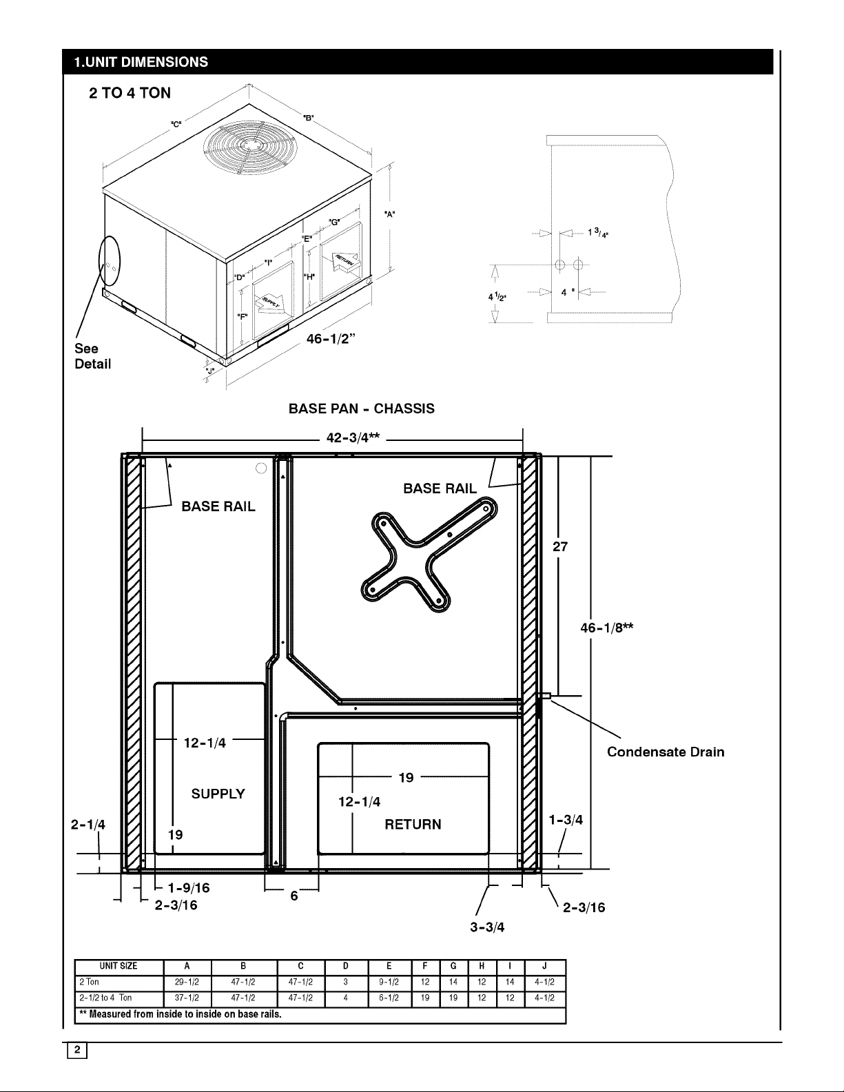
UNITSIZE A B C D E F G H I J
2Ton 29-1/2 47-1/2 47-1/2 3 9-1/2 12 14 12 14 4-1/2
2-1/2 to4 Ton 37-1/2 47-1/2 47-1/2 4 6-1/2 19 19 12 12 4-1/2
** Measured from inside to inside on base rails.
121
Condensate Drain
!
Page 3
2. SAFE INSTALLATION REQUIREMENTS
FIRE AND ELECTRICAL SHOCK HAZARD
Failure to carefully read and follow all instructions in this
manual could result in furnace malfunction, personal
injury, death and/or property damage.
Installation or repairs made by unqualified persons can
result in hazards to you and others. Installation MUST
conform with local building codes or, in the absence of
local codes, with the National Electrical Code
NFPA70-2005 or in Canada and CSA C.22.1 - Canadian
Electrical Code Part 1.
The information contained in this manual is intended for
use by a qualified service technician familiar with safety
procedures and equipped with the proper tools and test
instruments.
• Seal supply and return air ducts.
• Check to see that filters are installed correctly and are
the proper type an size.
NOTE: It isthe personal responsibility and obligation of the
customer to contact a qualified installer to ensure that the
installation is adequate and conforms to governing codes
and ordinances.
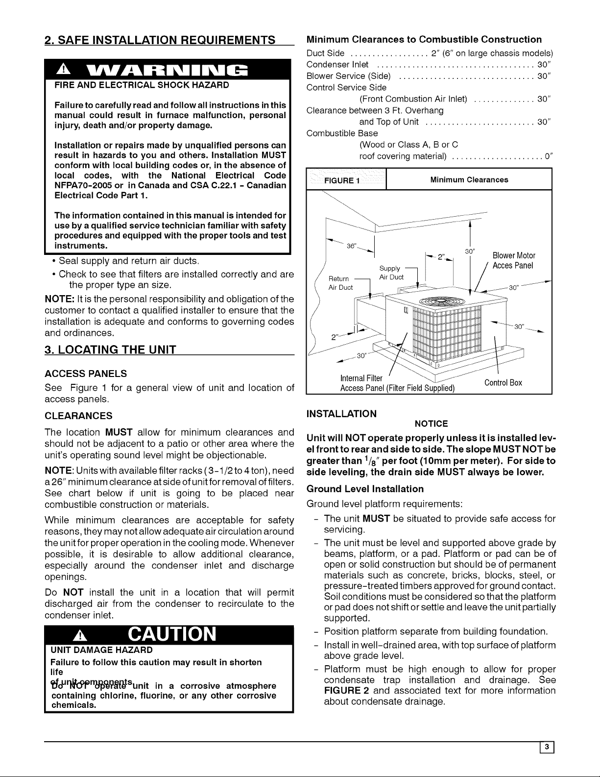
Minimum Clearances to Combustible Construction
Duct Side .................. 2" (6" on large chassis models)
Condenser Inlet .................................... 30"
Blower Service (Side) ............................... 30"
Control Service Side
(Front Combustion Air Inlet) .............. 30"
Clearance between 3 Ft. Overhang
and Top of Unit ......................... 30"
Combustible Base
(Wood or Class A, B or C
roof covering material) ..................... 0"
FIGURE 1J Minimum Clearances
_..
Return _ ASuPDPluYc!j_ AccesPanel
Air Duct [_:_ _ .... _ .J/30 ....
-1_ _i_tDr_t___ _ t _.... "_ 2"_ Blower Motor
' __'_:_:_ 30
3. LOCATING THE UNIT
ACCESS PANELS
See Figure 1 for a general view of unit and location of
access panels.
CLEARANCES
The location MUST allow for minimum clearances and
should not be adjacent to a patio or other area where the
unit's operating sound level might be objectionable.
NOTE: Units with available filter racks (3-1/2 to 4 ton), need
a26" minimum clearance at side of unit for removal of filters.
See chart below if unit is going to be placed near
combustible construction or materials.
While minimum clearances are acceptable for safety
reasons, they may not allow adequate air circulation around
the unit for proper operation inthe cooling mode. Whenever
possible, it is desirable to allow additional clearance,
especially around the condenser inlet and discharge
openings.
Do NOT install the unit in a location that will permit
discharged air from the condenser to recirculate to the
condenser inlet.
UNIT DAMAGE HAZARD
Failure to follow this caution may result in shorten
life
Ci_oU_ltooprr_°e_r_Sunit in a corrosive atmosphere
containing chlorine, fluorine, or any other corrosive
chemicals.
)
nerna I er
AccessPanel(FilterFieldSupplied)
INSTALLATION
NOTICE
Unit will NOT operate properly unless it is installed lev-
el front to rear and side to side. The slope MUST NOT be
greater than 1/8" per foot (10mm per meter). For side to
side leveling, the drain side MUST always be lower.
Ground Level Installation
Ground level platform requirements:
- The unit MUST be situated to provide safe access for
servicing.
- The unit must be level and supported above grade by
beams, platform, or a pad. Platform or pad can be of
open or solid construction but should be of permanent
materials such as concrete, bricks, blocks, steel, or
pressure-treated timbers approved for ground contact.
Soil conditions must be considered so that the platform
or pad does not shift or settle and leave the unit partially
supported.
- Position platform separate from building foundation.
- Install inwell-drained area, with top surface of platform
above grade level.
- Platform must be high enough to allow for proper
condensate trap installation and drainage. See
FIGURE 2 and associated text for more information
about condensate drainage.
Page 4
Rooftop Installation
Rooftop platform requirements:
- The unit MUST be situated to provide safe access for
servicing.
- The existing roof structure MUST be adequate to
support the weight of the unit or the roof MUST be
reinforced.
Check the weight of the unit in relation to the roof
structure and local building codes or ordinances and
reinforce roof structure if necessary. See page 11 of this
manual for unit weights.
- Support for the unit MUST be level and strong enough
to carry unit weight. The support may consist of a
platform or a combination of platform and roof beams or
curb.
- See Hoisting section for hoisting instructions.
HOISTING
NOTE: All access panels MUST be secured in place before
hoisting.
The unit should be hoisted with two lifting slings. Attach the
slings to rigging shackles that have been hooked through
holes in the base rail.
Two spreader bars MUST be placed on top of the unit to
protect the unit from damage from the pressure exerted by
the slings. Make sure that all equipment is adequate to
handle the weight ofthe unit and that the slings will not allow
the unit to shift.
Refer to FIGURE 9 on page 11 ofthis manual for illustrated
rigging instructions and weight chart.
DOWNFLOW CONVERSION
NOTE: In downflow applications with roof curbs or jack
stands, the center rail under the unit must be removed. The
center rail is attached to the base rail with screws.
These units are adaptable to downflow use. To convert to
downflow use, follow these steps:
1. Remove the blockoff plates found in the return air
compartment and the supply air compartment.
NOTE: Blockoff plate in the supply air compartment only
contains one screw. If reinstalling plate, back part of plate
MUST fit into mating dimples on flange. To reinstall, slant
plate into dimples, then put plate into position and fasten
with screw.
2. Install the removed plates on the horizontal return and
supply air openings.
3. Install roof curb on the building. Be sure to follow all
directions included with curb and all applicable building
codes in your installation.
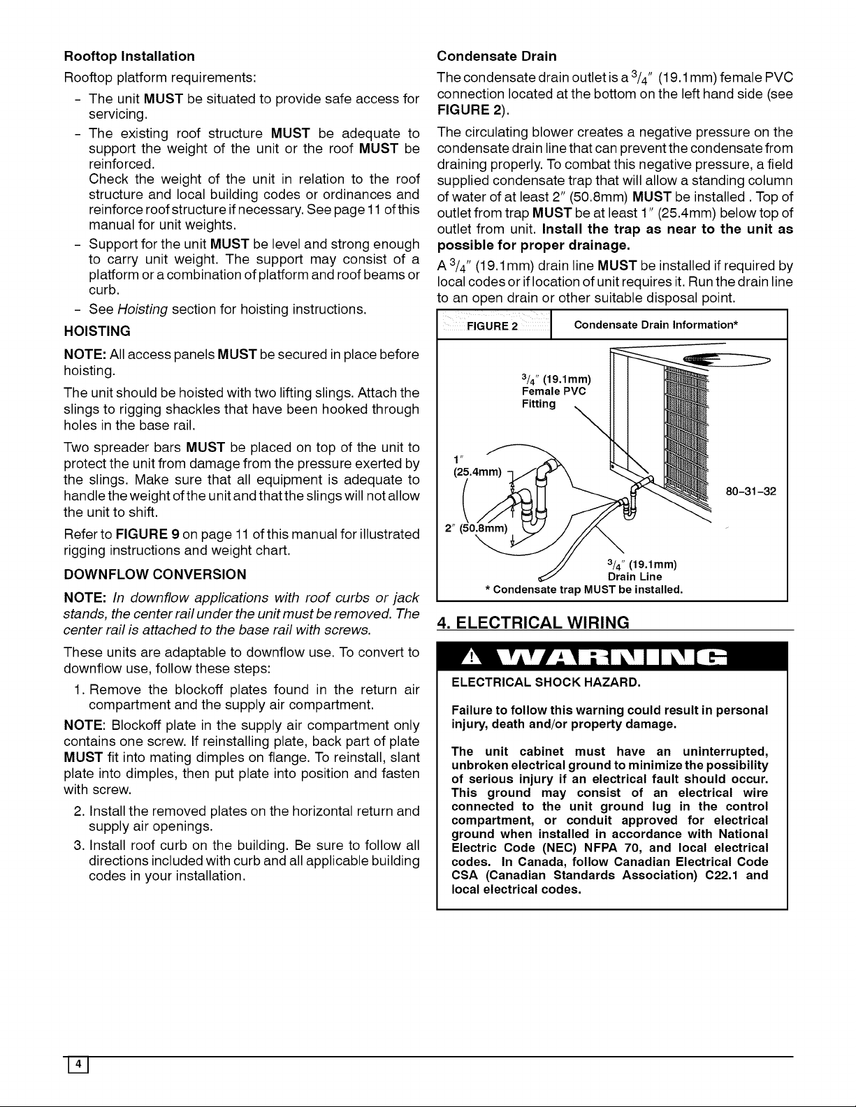
Condensate Drain
The condensate drain outlet is a 3/4" (19.1 mm) female PVC
connection located at the bottom on the left hand side (see
FIGURE 2).
The circulating blower creates a negative pressure on the
condensate drain linethat can prevent the condensate from
draining properly. To combat this negative pressure, a field
supplied condensate trap that will allow a standing column
of water of at least 2" (50.8mm) MUST be installed. Top of
outlet from trap MUST be at least 1" (25.4mm) below top of
outlet from unit. Install the trap as near to the unit as
possible for proper drainage.
A 3/4" (19.1 mm) drain line MUST be installed if required by
local codes or iflocation of unit requires it. Run the drain line
to an open drain or other suitable disposal point.
CondensateDrain,n,ormatlon*
3/4" (19.1mm)
Female PVC
Fitting _
\
(25.4mm)
80-31-32
(
2" (50,8ram)
3/4" (19.1mm)
Drain Line
* Condensate trap MUST be installed.
4. ELECTRICAL WIRING
ELECTRICAL SHOCK HAZARD.
Failure to follow this warning could result in personal
injury, death and/or property damage.
The unit cabinet must have an uninterrupted,
unbroken electrical ground to minimize the possibility
of serious injury if an electrical fault should occur.
This ground may consist of an electrical wire
connected to the unit ground lug in the control
compartment, or conduit approved for electrical
ground when installed in accordance with National
Electric Code (NEC) NFPA 70, and local electrical
codes. In Canada, follow Canadian Electrical Code
CSA (Canadian Standards Association) C22.1 and
local electrical codes.
141
Page 5

REDUCED EQUIPMENT LIFE HAZARD
Failure to follow these precautions could result in
damage to the unit being installed.
1) Make all electrical connections in accordance with
National Electric code (NEC) NFPa 70 and local electrical
codes governing such wiring. In Canada, all electrical
connections must be in accordance with CSA standard
C22.1, Canadian Electrical Code Part 1, and applicable
local codes. Refer to unit wiring diagram.
2) Use only copper conductor for connections
between field-supplied electrical disconnect switch and
unit. DO NOT USE ALUMINUM WIRE.
3) Be sure that high-voltage power to unit is within
operating voltage range indicated on unit rating plate.
4) Do not damage internal components when drilling
through any panel to mount electrical hardware,
conduit, etc. Consult local power company for
correction of improper voltage and/or phase imbalance.
Disconnect Switch
The unit must have separate electrical service with a
field-supplied, waterproof, disconnect switch mounted at,
or within sight from, the unit. Refer tothe unit rating plate for
maximum fuse/circuit breaker size and minimum circuit
amps (ampacity) for wire sizing.
Ground Connections
Do NOT complete line voltage connections until unit is
permanently grounded. All linevoltage connections and the
ground connection MUST be made with copper wire.
A ground lug is installed in the control box area for the
ground connection. Use a copper conductor of the
appropriate size from the unit to a grounded connection in
the electrical service panel or a properly driven and
electrically grounded ground rod. See warning above.
Line Voltage Wiring - (Wiring Diagrams page 12 & 13)
Connections for linevoltage are made in the unit control box
area. Refer to wiring diagram located on the Access panel.
For access, remove the burner access panel.
1. Run the high voltage (L1, L2) and ground leads into the
control box.
2. Connect ground lead to chassis ground connection.
3. Connect L1 to pressure lug connection 11 of the
compressor contactor.
4. Connect L2 to pressure lug connection 23 of the
compressor contactor.
Thermostat / Low Voltage Wiring
Location of the thermostat has an important effect on home
comfort. FOLLOW THE THERMOSTAT INSTRUCTION
MANUAL FOR CORRECT LOCATION, MOUNTING, AND
WIRING.
For 2 to 3-1/2 Ton Models Only:
A single stage thermostat is required for proper operation.
Thermostat must have the terminals shown in Figure 3 or
there equivalent. Some electronic thermostats use low
voltage from the unit for power for temperature display and
programming. These electronic thermostats will have a "C"
terminal. The outdoor unit has color-coded wires for easy
connection. Using wire nuts, follow Figure 3 for proper
connections:
FIGURE 3 2 to 3-1/2 Ton Thermostat Connections
Thermostat and subbase Unit Control Power
For 4 Ton Models Only:
A two-stage thermostat is required for proper operation.
Thermostat should have the terminals shown in Figure 4 or
there equivalent. Some electronic thermostats use low
voltage from the unit for power for temperature display and
programming. These electronic thermostats will have a "C"
terminal. The outdoor unit has color-coded wires for easy
connection. Using wire nuts, follow Figure 4 for proper
connections:
FIGURE 4 4 Ton Thermostat Connections
Thermostat and subbase Unit Control Power
THERMOSTAT HEAT ANTICIPATOR
Some thermostats have an adjustable heat anticipator. The
heat anticipator prevents temperature overshoot in heating
mode. If the heat doesn't turn off until the set point
temperature on the thermostat is exceeded, then the
anticipator setting istoo low. If the heat turns off before the
thermostat reaches the set point temperature on the
thermostat, then the anticipator setting is too high. Follow
the thermostat instruction manual for proper adjustment of
the heat anticipator.
Page 6

Final Electrical Check Ductwork Connections
1. Make a final wiring check to be sure system is correctly
wired. Inspect field installed wiring and the routing to
ensure that rubbing or chafing due to vibration will not
occur.
NOTE: Wiring MUST be installed so it is protected from
possible mechanical damage.
5. DUCTWORK
Ductwork Sizing
The maximum recommended velocity in trunk ducts is 1000
feet per minute. The maximum recommended velocity in
branch ducts is 800 feet per minute.
Ductwork sizing affects the discharge temperature, airflow
velocity, and efficiency of the system. Be sure to properly
size ductwork to the capacity of the unit and to the airflow
requirements of the conditioned space. Failure to properly
size ductwork can result in inadequate airflow and poor
The use of flexible, non-combustible connectors between
main trunk ducts and supply and return air plenums is
permitted. If flexible connectors are used, they should be
protected from potential mechanical damage such as
punctures and tears.
NOTE: When connecting the supply and return plenums to
the unit, make sure that the plenums are sealed against the
side casing of the unit and do not interfere with removal of
the top of the unit.
FILTERS
All return air MUST pass through a filter before entering the
unit. An electronic air cleaner, optional filter racks, or other
accessible filter arrangement must be installed in the return
air ductwork. Minimum recommended filter sizes are listed
in FIGURE 5 and are based on maximum face velocities of
300 ft/min for disposable filters and 500 ft/min for washable
(high velocity) filters. See figure 5 for filter sizes.
efficiency. Undersized ductwork may result in tripped limit
controls and premature failure of compressors, motors and
other components.
REDUCED EQUIPMENT LIFE HAZARD
Ductwork Insulation
Ductwork installed outdoors must have a minimum 2" thick
fiberglass "wrap" insulation and a weatherproof vapor
barrier installed around it. The insulation and vapor barrier
Failure to follow this caution may result in improper
unit operation.
Do not operate the unit without a filter.
must be protected against potential damage. Caulking,
flashing, and other means of providing a permanent
weather seal must be used.
FIGURE 5 Filter Sizes
PHF3 Filter sizes
Model
PHF324000K00A1
PHF330000K00A1
PHF336000K00A1
PHF342000K00A1
PHF348000K00A1
Disposable Filters
Nominal Size
(Qty x w x d)
1 x 20" x 20"
1 x 20" x 24"
2 x 15" x 20"
2 x 18" x 20"
2 x 20" x 20"
Minimum Area
(sq inches)
384
480
576
672
768
Wasable Filters
Nominal Size
(Qty x w x d)
1 x 12" x 20"
1 x 15" x 20"
1 x 18" x 20"
1 x 20" x 20"
1 x 20" x 24"
Minimum Area
(sq inches)
231
288
346
404
461
Page 7

6. AIRFLOW ADJUSTMENT
CIRCULATING AIR BLOWER SPEEDS
BLOWERPERFORMANCEDATA
_odel Number PHF324000K00AI PHF330000K00AI
3peedTap 1 2 3 4 1 2 3 4
0.1 891 1136 986 1076 1286 1352
0.2 845 1098 949 1038 1225 1311
AirDelivery in
CFM@ Varying
ExternalStatic
Pressure (in,
W.C.)
0.3 804 1056 908 997 1186 1274
0.4 758 1020 856 973 1158 1233
0.5 707 980 819 913 1129 1203
0.6 649 920 781 875 1085 1162
0.7 582 785 717 840 1044 1119
0.8 509 569 664 786 1004 1066
0.9 318 612 717 948 989
1 554 659 755 774
Notes:Air Delivery@ listedexternalstatic pressrearetaken at230Voltswith Drycoil, no filterandapprovedheater.
Forwet coil add .05in. wc. toStatic Pressuremeasurement.Notefor 208Volts applications,reduceairflowby15%.
PHF336000K00A1
1 2 3 4
1162 1278 1529 1652
1118 1233 1484 1607
1062 1191 1440 1574
1014 1149 1402 1541
958 1108 1364 1501
892 1060 1326 1462
826 1005 1284 1426
780 943 1238 1384
735 892 1179 1338
675 844 1123 1277
PHF342000K00A1 PHF348000K00A1
1 2 3 4 1 2 3 4
1138 1240 1505 1643 1154 1245 1750 1908
1087 1189 1467 1609 1084 1170 1696 1864
1041 1145 1431 1577 1005 1110 1643 1819
989 1104 1398 1541 940 1034 1592 1770
940 1063 1363 1509 880 972 1547 1720
865 1010 1324 1476 832 924 1497 1678
806 952 1283 1439 780 875 1443 1632
752 891 1234 1402 713 836 1400 1586
694 828 1175 1352 663 773 1354 1538
646 773 1120 1264 613 720 1302 1494
FIGURE 6
Blower Tap Connections
Blower Speed Tap Settings
PHF324000K
PHF330000K
PHF336000K
PHF342000K
PHF348000K
Rated Airflow
Speed Tap 1
Speed Tap 2
Speed Tap 2
Speed Tap 3
Speed Tap 3(Hi);2(Lo)
High Airflow
Speed Tap 3
Speed Tap 3
Speed Tap 3
Speed Tap 4
Speed Tap 4 (Hi);3(Lo)
Verify that the proper blower speeds for heating and cooling
are selected on the blower motor by removing the blower
access panel and inspecting the blower motor. The motor
has 4 speeds numbered "1", "2", "3", and "4". The wires for
the speed selection are as follows:
Red _ Heating
Black _ High Stage Cooling
Violet _ Low Stage Cooling (4 ton only)
Using the same speed for Heating and Cooling.
If the same speed is required for heating and high stage
cooling the following procedure must be used:
1. Set Red wire on proper speed selection on blower
motor.
2. Remove Black wire from "COOL" (2 - 3.5 Ton models)
or "HI" (4 Ton Model) on Blower Interface Board. Tape
end of Black lead using electrical tape.
3. Jumper the Red wire to both the "Heat" terminal and
either the "COOL" (2 - 3.5 Ton models) or "HI" (4 Ton
Models) terminal on the Blower Interface Board.
If the same speed is required for heating and low stage
cooling (4 Ton model only), the following procedure must be
used:
1. Set Red wire on proper speed selection on blower
motor.
2. Remove Violet wire from "LO" on Blower Interface
Board. Tape end of Violet lead using electrical tape.
3. Jumper the Red wire to both the "Heat" terminal and the
"LO" terminal on the Blower Interface Board.
I
7. START-UP PROCEDURES
CHECK BEFORE STARTING
1. Check that the blower motor speed terminal block is
running the correct heating and cooling speeds.
2. Check to see that clean, properly sized air filters are
installed.
3. Replace all service access panels.
Check the unit's operation as outlined in the following
instructions. If any unusual sparking, odors or unusual
noises are encountered, shut off electric power
immediately. Recheck for wiring errors, or obstructions in or
near blower motors.
1. Set thermostat Heat-Cool selector to OFE
2. Set thermostat fan switch to AUTO.
3. Turn electric power ON. Nothing should start running.
4. Set thermostat fan switch to ON.
5. Reset thermostat fan switch to AUTO.
Page 8

8. SEQUENCE OF OPERATION
ELECTRICAL SHOCK HAZARD.
Failure to follow this warning could result in personal
injury, death and/or property damage.
Turn off electric power supply at disconnect switch or
service panel before removing any access or service
panel from unit.
Cooling Operation (PHF324 -42)
With a call for cooling (Y), the indoor fan energizes
immediately where as the contactor energizes after a 5
minute time delay (incase of an initial start up) starting the
compressor and the outdoor fan motor. When the cooling
demand ismet, (Y) de-energizes, shutting the compressor,
indoor fan and the outdoor fan.
Cooling Operation (PHF348)
These units utilize a 2 stage indoorthermostat. With a first
stage call for cooling (Y1), the indoor fan (low stage)
energizes immediately where as the contactor energizes
after a 5 minute time delay (incase of an initial start up)
starting the compressor (low stage) and the outdoor fan
motor. Ifthe low stage operation cannot satisfy the cooling
demand, the second stage cooling (Y2) energizes
switching the compressor into high stage cooling through
energizing an internal solenoid valve inside the scroll
compressor and switching the indoor fan into high stage.
When second stage cooling is satisfied, Y2 de-energizes
switching the compressor and the indoor fan into low stage
cooling. When the low stage cooling demand is met, Y1
de-energizes shutting the compressor, indoor fan and the
outdoor fan.
Heating Operation (PHF324 -42)
With a call for heating (Y), the indoor fan (low stage)
energizes immediately where as the contactor energizes
after a 5 minute time delay (incase of an initial start up)
starting the compressor and the outdoor fan motor. If (Y)
cannot satisfy the heating demand, the auxiliary or back up
heat (W2) energizes. Incase of staged heating, W3 is
energized if the demand is not met. The highest airflow
selected is run while the electric heat is in operation. When
heating demand is met, W3, W2 and Y sequentially
de-energize shutting the compressor, indoor fan and the
outdoor fan.
Heating Operation (PHF348)
With a first stage call for heating (Y1), the indoor fan (low
stage) energizes immediately whereas the contactor
energizes after a 5 minute time delay (incase of an initial
start up) starting the compressor (low stage) and the
outdoor fan motor. Ifthe low stage operation cannot satisfy
the heating demand, the second stage heating (Y2)
energizes switching the compressor into high stage heating
through energizing an internal solenoid valve inside the
scroll compressor and switching the indoor fan into high
stage. The auxiliary or back up heat is controlled by a third
stage (W2). If the demand is not met, W3 is energized in
case of staged heating. When heating demand is satisfied,
W3, W2 and Y2 sequentially de-energize switching the
compressor and the indoor fan into low stage heating.
When the low stage heating demand is met, Y1
de-energizes shutting the compressor, indoor fan and the
outdoor fan.
Scroll Recycle Delay timer
The defrost board is equipped with a recycle delay timer
which will delay the start of the compressor for 5 minutes in
the event of a power interruption. This sequences power
throughout the system and prevents possible reverse
rotation of the scroll compressor. The output of the timer
controls the compressor contactor via a normally open
contact of K3 (T2). The timer starts the delay cycle when the
compressor is turned off by removal of "Y." If application of
"Y" occurs before the timer has expired, the compressor
contactor will not be energized until the timer has expired.
CONTINUOUS FAN OPERATION
With the continuous Indoor fan option selected on the
thermostat, G is continuously energized. Incase of 024 -
042 units, the selected airflow setting is provided. Incase of
048 units, the system runs low stage (Y1) airflow for
continuous fan operation.
Defrost Mode
On a call for defrost:
When the defrost sensor closes in the heating mode, there
is a 30, 60, 90 or 120 minute delay before the defrost mode
begins. This delay is selected by the position of the
dipswitches on the defrost board. Defrost interval timing
can be configured by selection switch 1 and 2 on the
dipswitch per the following table: See Figure 7.
Switch 1
ON
OFF
OFF
ON
NOTES:
1. The backup
minutes.
Switch 2 Time
OFF 30 Minutes
ON 60 Minutes
OFF 90 Minutes
ON 120 Minutes
defrost terminate time is fixed at 10
2. The compressor recycle delay timer is 5 minutes.
3. The power interrupt response is minimum 17 msec. to
maximum 35 msec.
4. Quite shift compressor recycle delay is 30 seconds.
In normal defrost mode, the following sequence will occur
after the set delay:
1. Condenser fan off.
2. Reversing valve energized to cooling and auxiliary
electric heat (W2) is energized.
3. After defrost sensor opens or a maximum of 10
minutes; the condenser fan is energized (after 20
seconds) and the reversing valve is de-energized to
the heat mode. Electric strip heat is also de-energized
(after 15 seconds) except as required by the
thermostat.
4.
Should the system indoor thermostat be satisfied
during the defrost cycle, the control will de-energize the
Page 9

reversingvalveandauxiliaryheatoutputsand"hold"
thedefrosttimeruntilthenextcallforheat,atwhichtime
thedefrostcyclewillbecompleted.
Servicetesting:the pins marked"speedup" when
momentarilyshortedtogether(for5seconds)andreleased,
willdefeatthe5 minutesrecycledelaytimerandallowthe
compressorcontactorto beimmediatelyenergized,thus
forcingadefrostcycle.Terminationofthisforcedmodewill
bebythedefrostthermostatorthe10minutebackuptimer,
providedthe defrostthermostatwas closedwhenthe
defrostwas"forces."If thedefrostthermostatwasnot
closed,atthetimeofthe"forceddefrost,"thedefrostmode
willremainfor30secondsandthenterminate.
Defrost Board & Dip Switches
Defrost Board
Dip Switch
9. MAINTENANCE
MONTHLY MAINTENANCE AND INSPECTION
CHECKS
Air Filters
REDUCED EQUIPMENT LIFE HAZARD
Failure to follow this cautions may result in damage to
the unit being installed.
Do not operate the unit without a filter.
Inspect filters at least monthly and replace or clean as
required. Washable filters may be cleaned by soaking in
mild detergent and rinsing with cold water. Replace filters
with the arrows on the side pointing in the direction of air
flow. Dirty filters are the most common cause of inadequate
heating or cooling performance, and of compressor
failures.
COOLING SEASON CHECKS (MONTHLY)
Condenser Coil
Keep the condenser inlet and outlet area clean and free of
leaves, grass clippings or other debris. Grass should be
kept short in front of the condenser inlet. Shrubbery MUST
be trimmed back so it is no closer than 30 inches to unit.
Condensate Drain
Check for condensate drainage. Clean as required.
ANNUAL MAINTENANCE AND INSPECTION
ELECTRICALSHOCKHAZARD.
Failure to follow this warning could result in personal
injury, death and/or property damage.
Turn off electric power supply at disconnect switch or
service panel before removing any access or service
panel from unit.
The annual inspection should include cleaning as required
to ensure efficient operation of the unit. To simplify access,
remove all access panels and the top from the unit if
possible.
Condenser Fan Motor
Note: The condenser fan motor is permanently lubricated.
No further lubrication is required. Do not attempt to
lubricate the condenser fan motor.
Clean the surrounding area and the condenser and
evaporator coils. Use caution to avoid damage to coil fins.
BLOWER MOTOR ACCESS
Refer to Figure 1 for blower motor access panel and
compartment.
1. Remove the blower access panel
2. Remove the three screws securing the blower motor
housing. If unit has a support bracket, remove the two
screws securing the bracket.
3. Remove the two red wires attached to the limit
switchand remove the limit switch.
Motor removal and replacement
This method is required to replace or repair blower wheel,
blower housing, or any unreachable components behind
blower assembly.
1. Remove all screws around rim of unit top, (except
screws which are inaccessible because of proximity to
structure).
2. Raise unit top at corner of unit closest to blower at least
2" and place a sturdy brace at least 2" thick between top
and unit corner. A 2X4 piece of wood is ideal for this.
3. Disconnect all wires from housing and slide housing out
of unit. Reverse this process to reinstall.
Circulating Air Blower
Visually inspect the blower wheel for accumulations of dirt
or lint. Clean the compartment and the blower wheel. If
accumulation is excessive on blower wheel, or does not
easily remove, it will be necessary to remove the blower
assembly.
Note: The blower motor is permanently lubricated. No
further lubrication is required. Do not attempt to lubricate
the blower motor.
[2J
Page 10

Control Box
Control Plate
Capacitor Strap
Run Capacitor
Defrost
Board
Motor
Board
Transformer
Contactor
11ol
Page 11

10. Rigging Instructions
Rigging Instructions
O
t--
O
t--
O
O
O
09
O
O
F-
O9
_z
W
3
I
F--
O
__J
__J
O
L
O
F--
W
L
O
n
El- a
0
EtZ EtZ
EL o
_--)
_z
09--
LLI
O2>-
za
<_o
(Din
O
EtZ
__J
O
J
< w
W
W _
z
_w
_J_z
W_
Z_
_ >w
z_O
S8 £s
g_ m
W_<
©
<_ _
I
__1
<_
W
n_
O0
n_
w
n
W
O_
EL
-g
7-
__1
s_
Z ©
_z_
_z_
.__. r-
O_
c0
o
o
(D
b_
co
r-
o
7
I I
L!!_1
Page 12

10. Wiring Diagrams
FIELD
SUPPLY -- B[K
POWER ±
SIZE 2 AWG. _2
EQUIP GNt
FOR WIRINGWI'IH I--/--_ ] I I
E_:c'mmI.e.Kms I_ I / I
_ ._-'.1 L I _ I
ONHEA'IBRACCeSSO_[L ...............__ L_
l I
l 11
E
o_
t_
03
O=
.i
a
03
C
.i
!.--
C
,T,,I
I
_)
O
R
Y
0
w2
I , "COMPRESSOR P UG
L ......
DE_ROS] BOARD (DB)
BLU LPS 8LU
PL 1
ACCESSSORY ELECTRIC
HR1,2,3 & 4 (20
SEE NOTE #8
iRI (5
LS
W3
UNIT COMPONENTARRANGEMENT
OUTDOOR FAN
SECTION
INDOOR FAN
SECTION
@
CONIROL BOX AREA
--GND
EQUIP,
DISCONNECT
PERNED
--24V POWER
ENTRY
HR1 & 2 (10 KW)
@!,2 & 5 (15
EGEND
F_E_D SPLICE _AP CONTACTOR
C>TERNINAL (_ARKED) CAPACITOR
o TERMINAL INK_ARKER) CB CIRCUIT BREAKER
o SPLICE CCN CRANK CASE HEATER
{L> SPLICE (NANKED) CTD CONPREGSOR TINE DELAY
--FACTORY WIRING DB DEFROST BOARD
FIELD CONTROL WIRING DRT DEFROST THERMOSTAT
........... FIELD POWER WINING DR DEFROST RELAY
ACCESSORY OR OPIIONAL KCN FAN CONTROL BOARD
WIRING
--TO INDICATE CONNON IFM INDOOR FAN NOTOR
POTENTIAL ONLY:
NOT TO REPRESENT WINING LPS LOW PRESSURE SWITCH
NOTES:
l, IF ANY OF THE ORIGINAL _IRE$ FURTHER ARE REPLACED,
IT MUST SN RNPLANED WITN TYPE 90 DNGRNE C WIRE OR
2 SEN PRICE PAGES FOR TRERNOSTAT AND SURSASES
!T'S EQUIVALENT,
3 USE 75 DEGREE COPPER CONDUCTORS FOR FIELD INSTALLATION
4, iACIORY WIRING FOR SPEED SELECTOR PLUG. O G
024 "1 ENERGIZED DEENERGIZND
o30 ]_
OKR
OKR K
7. DEFROST TIMER TO NR SET AT 60 KIN.
8, LLS NSED ON 024 UNIFS ONLY,
CONP CONPRESSOR NOTOR
OND GROUND
NR HEATER RELAY
LLS LIQUID LINE SOLENOID
NPS HIGH PRESSURE SWITCH
Of M OUTDOOR FAN MOTOR
RVS REVERSING VALVE SOLENOID
TRAN TRANSFORMER
O T T+GD
CTD (TI,T2} COMPRESSOR DELAY
CLOSES OPENS
ISA_
Page 13

FIELD
SUPPLY
POWER
FOR WIRK; W]'111 [/--_
B.ECmmH_S I "._
sE SCH_t_C ....k_ I_
ON HEA'I_ ACCESSORY,
MAXIMUM WIRE--
UNIT ONIY [ L¶--
SIZE 2 AWG, L2
E©UZP GND
F--
I
BLN _ C B'rN--
_H
BL__
DR @ DB
YEL
BLK
SCHEMATIC
208/230-1-60
/77
PLUG
COMP SOL
1
[ [I
E
R --RED
I_ YI --YEL
J I
GRN--
--BLK -
TRANI
SEE NOTE #5_
MANUAL RESE[/
BRN
L
3,2 AMPw
BRN
_N
HPS
Y2 --P,_K
W3 .................................................rio-- i_
C --BRN .....................................................................
UNIT COMPONENT ARRANGEMENT
OUTDOOR EAR
SECTION
_ICE
BOX
INDOOR FAN
SECTION
@
CONTROLBOXARA
_--GRD
EQUIP,
RRSp o
FIELD SPLICE
o IERRINAL_UNMRRKED_ P CAPACITOR
<Z)TER_INAL (_ARKED) _C CONTRCTOR
o SPLICE CIRCUITBREAKER
<]3.SPLICE _RRNED) CORN COMPRESSOR_OTOR
--FACTORY WIRING CTD COMPRESSORTI_E DELAY
FIELD CONTROL WIRING DB DEFROSTBOARD
--- FIELD POWER WIRING DRT DEFROSTTNER_ORTAT
...........ACCESSORYOR OPTIONAL DR DEFROST RELAY
_IRING ECB FAN CONTROL BOARD
--TO INDICATECOR_ON RR HEATER RELAY
POIER]!AL ONLY: INN INDOOR RAN MOTOR
ROt ro REPRZRENIW!RING ERR LOW PRESSURE S_ITCR
NOTES:
i IF ANY OR THE ORIGINAL WIRES FURNISHED ARE REPLACED,
l! RUST BE REPLACED Wl]H TYPE RO DIRREE C WIRE OR
ll'S EOUIVALENII
, RED PRICE PAGES _OR [NERNOSTAT AND SRRRASES,
USE 75 DEGREE COPPER CONDUCTORS FOR FIELD INSTAUATION
4. DEFROST TINER TO BE SET AT 60 _IN.
5 RELOCATION OF SPEED TAPS NAY BE REQUIRED
WHEN USING FIELD INSTALLED ELECTRIC HEATERS,
CONSULT INSTALLATION INSTRUCTIONS TO
BETERRINE CORRECT SPEED TAP SETTING
6 "DO NOT DISCONNECT PLUG UNDER LOAD _
CCR CRANK CASE HEATER
GRD GROUND
DPS NIGH PRESSURESWITCH
ORR OUTDOORFAN _OTOR
RVS REVERSINGVALVE SOLENOID
TRAR TRRNRRORRDR
FIEL_ $ZLZCTABLZ OPTIONS rOD TI_E PERIOD
BET_VEE_ DEFROST CYCLES (_INUTZS}
TH_COmPReSSOR*iLLS_ ¸OF_¸_OR_ SEC,ONDEFROST
IN_ATIO_ AND_R_I_ArION_ F,E_IEI ¸S_IFT_ON
POSI_ON
_o_ ................................
_IEL_S_EEDUPCYCLE
I__O_TA_ILY SHORTPINS A_ R_LE_S_TO _YPASS
COMPRESSOROFF _LAY.
2}SHORTFOR_* SEC A_ RELEASEFOR_ORCE__EFROST
_ _ER_A_ENI¸SHORTWIL_ BE i_O_E_,
_ROST WrLLTERminATENO_MA_LY_ DFT_ CLO_ED
FA_ SEQUENCE CTD (T1,T2_ CONPRESSOR DELAY
& _ €so D.SSEc T+S.IN.
G O ci ci
E_ERGIZED DE-ENERGIZED CLOSES OPENS
TSAT
I 50CU500139 I10,0
 Loading...