

Page 1
NTGM/GNK Series
Upflow/Horizontal
NCGM/GCK Series
Downflow/Horizontal
SAFETY REQUIREMENTS
Recognize safety information. This is the safety-alert symbol _. When you see this symbol on the furnace and in instructions or
manuals be alert to the potential for personal injury.
Understand the signal words DANGER, WARNING, or CAUTION. These words are used with the safety-alert symbol. DANGER
identifies the most serious hazards, those that will result in severe personal injury or death. WARNING signifies a hazard that could
result in personal injury or death. CAUTION is used to identify unsafe practices that could result in minor personal injury or product and
property damage.
Installing and servicing heating equipment can be hazardous due to gas and electrical components. Only trained and qualified person-
nel should install, repair, or service heating equipment.
Untrained service personnel can perform basic maintenance functions such as cleaning and replacing air filters. All other operations
must be performed by trained service personnel. When working on heating equipment, observe precautions in the literature, on tags,
and on labels attached to or shipped with the unit and other safety precautions that may apply.
Follow all safety codes. In the United States, follow all safety codes including the current edition National Fuel Gas Code (NFGC) NFPA
No. 54/ANStZ223.1. In Canada, refer tothe current edition ofthe National Standard Canada CAN/CGA-B149.1 - and .2-M91 Natural
Gas and Propane Installation Codes (NSCNGPIC). Wear safety glasses and work gloves. Have fire extinguisher available during start-
up and adjustment procedures and service calls.
These instructions cover minimum requirements and conform to existing national standards and safety codes. In some instances,
these instructions exceed certain local codes and ordinances, especially those that may not have kept up with changing residential
construction practices. We requre these instructions as a minimum for a safe installation.
Design Certified
byAGA
/X
Manufactured by:
International Comfort Products Corporation (USA)
Lewisburg, TN USA 37091
Table of Contents
1.SafeInstallationRequirements................ 2
2.Installation............................... 4
3.Combustion&VentilationAir ................ 9
4.Vent& CombustionAirPiping ................ 11
5.GasSupplyandPiping ...................... 19
6.ElectricalWiring ........................
7.DuctworkandFilter(Upflow/Horizontal)......
8.DuctworkandFilter(Downflow/Horizontal)....
9. ChecksandAdjustments.................
10.FurnaceMaintenance ...................
11.ConcentricVentTermination..............
Fire or Explosion hazard.
This furnace is not designed for use in mobile
homes, trailers or recreational vehicles.
Such use could result in death, bodily injury
and/or property damage.
LP1 6/9/2000 440 01 1002 01
22
23
25
28
30
30
Page 2
1.Safe InstallationRequirements
Installation or repairs made by unqualified
persons can result in hazards to you and others.
Installation MUST conform with local codes or, in
the absence of local codes, with codes of all
governmental authorities having jurisdiction.
The information contained in this manual is
intended for use by a qualified service technician
who is experienced in such work, who is familiar
with all precautions and safety procedures
required in such work and is equipped with the
proper tools and test instruments.
Failure to carefully read and follow all instruc-
tions in this manual can result in furnace
malfunction, death, personal injury and/or
property damage.
NOTE: This furnace is design certified by the American Gas
Association and the Canadian Gas Association for installation in
the United States and Canada. Refer to the appropriate codes,
along with Figure 1 or Figure 2 and this manual, for proper instal-
lation.
• This furnace is NOT approved for installation in mobile
homes, trailers or recreation vehicles.
Do NOT use this furnace as aconstruction heater or to heat
a building that is under construction.
Use only the Type of gas approved for this furnace (see
Rating Plate on unit). Overfiring will result in failure of heat
exchanger and cause dangerous operation. (Furnaces can
be converted to L.P. gas with approved kit.)
• Do NOT use open flame to test for gas leak.
• Ensure adequate combustion and ventilation air is pro-
vided to the furnace.
• Seal supply and return air ducts.
• The vent system MUST be checked to determine that it is
the correct type and size.
• Install correct filter type and size.
• Unit MUST be installed so electrical components are pro-
tected from direct contact with water.
NOTE: It is the personal responsibility and obligation of the end
user to contact a qualified installer to ensu rethat the installation is
adequate and conforms to governing codes and ordinances.
SafetyRules
Your unit is built to provide many years of safe and dependable
service providing it is properly installed and maintained. However,
abuse and/or improper use can shorten the life of the unit and
create hazards for you, the owner.
A. The U.S. Consumer Product Safety Commission recom-
mends that users of gas-burning appliances install carbon
monoxide detectors. There can be various sources of car-
bon monoxide in a building or dwelling. The sources could
be gas-fired clothes dryers, gas cooking stoves, water
heaters, furnaces, gas-fired fireplaces, wood fireplaces,
and several other items. Carbon monoxide can cause seri-
ous bodily injury and/or death. Therefore, to help alert
people of potentially dangerous carbon monoxide levels,
you should have carbon monoxide detectors listed by a na-
tionally recognized agency (e.g. Underwriters Laboratories
or International Approval Services) installed and main-
tained in the building or dwelling (see Note below).
B. There can be numerous sources of fire or smoke in a build-
ing or dwelling. Fire or smoke can cause serious bodily inju-
ry, death, and/or property damage. Therefore, in order to
alert people of potentially dangerous fire or smoke, you
should have fire and smoke detectors listed by Underwrit-
ers Laboratories installed and maintained in the building or
dwelling (see Note below).
Note: The manufacturer of your furnace does not test any de-
tectors and makes no representations regarding any brand
or type of detector.
C. To ensure safe and efficient operation of your unit, you
should do the the following:
1. Thoroughly read this manual and labels on the unit.
This will help you understand how your unit operates and
the hazards involved with gas and electricity.
2. Do not use this unit if any part has been under water.
Immediately call a qualified service technician to inspect
the unit and to replace any part of the control system and
any gas control which has been under water.
3. Never obstruct the vent grilles, or any ducts that pro-
vide air to the unit. Air must be provided for proper com-
bustion and ventilation of flue gases.
Carbon monoxide or "CO" is a colorless and odorless gas
produced when fuel is not burned completely or when the
flame does not receive sufficient oxygen.
FreezingTemperaturesandYourStructure
Freeze warning.
Turn off water system.
If your unit remains shut off during cold weather
the water pipes could freeze and burst, resulting
in serious water damage.
Your unit is equipped with safety devices that may keep itfrom op-
erating if sensors detect abnormal conditions such as clogged ex-
haust flues.
Ifthe structure will be unattended during cold weather you should
take these precautions.
1. Turn off main supply water into the structure and drain the
water lines if possible. Open faucets in appropriate areas.
2. Have someone check the structure frequently during cold
weather to make sure it is warm enough to prevent pipes
from freezing. Suggest they call qualified service agency, if
required.
[_ 44001 100201
Page 3
Dealer Name:
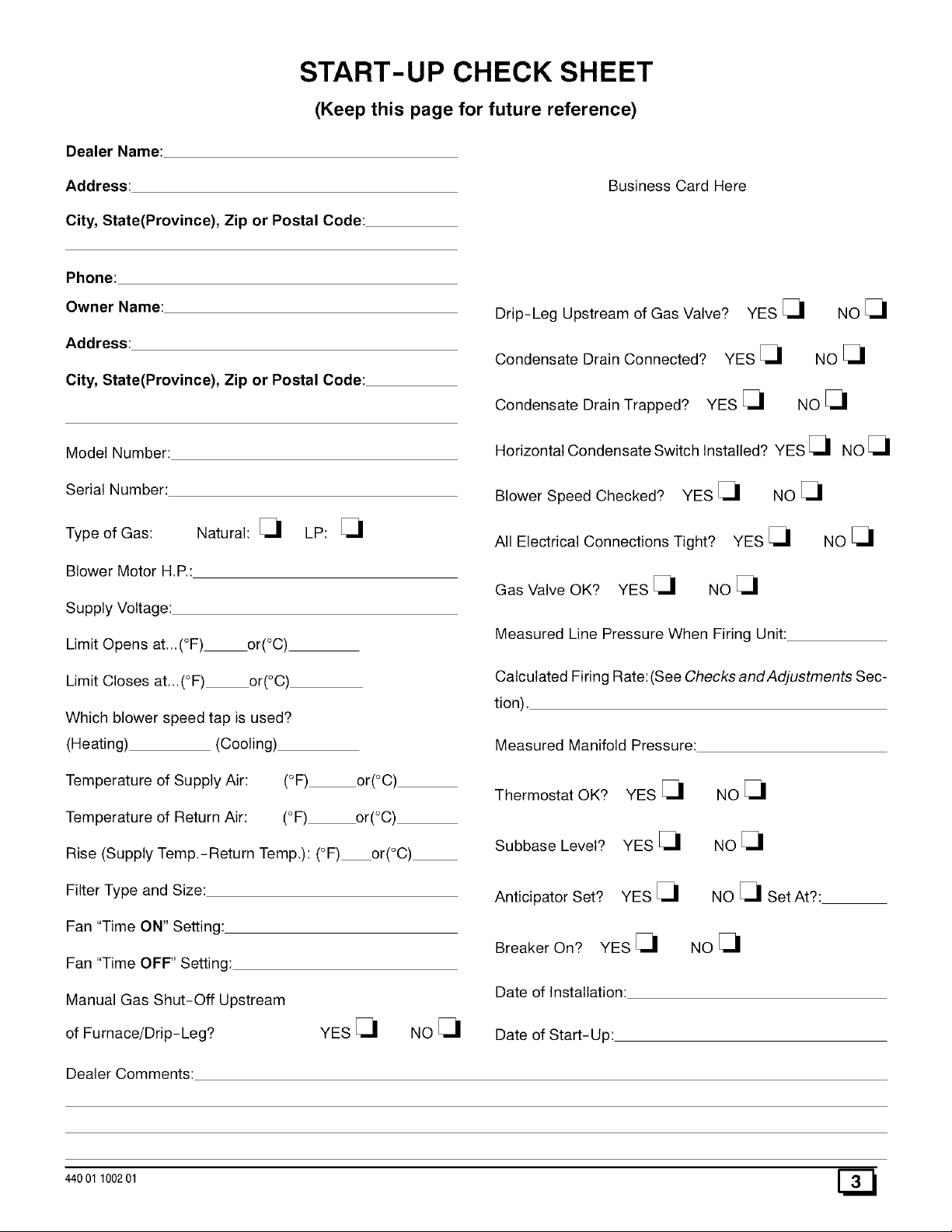
START-UP CHECK SHEET
(Keep this page for future reference)
Address:
City, State(Province), Zip or Postal Code:
Phone:
Owner Name:
Address:
City, State(Province), Zip or Postal Code:
Model Number:
Serial Number:
Type of Gas:
Blower Motor H.P.:
Supply Voltage:
Limit Opens at...(°F) or(°C)
Natural: _1 LP: _1
Business Card Here
Drip-Leg Upstream of Gas Valve?
Condensate Drain Connected? YES _1
Condensate Drain Trapped? YES _1
Horizontal Condensate Switch Installed? YES _1 NO _1
Blower Speed Checked? YES _1 NO _1
All Electrical Connections Tight? YES _1 NO _1
Gas Valve OK? YES _1 NO _1
Measured Line Pressure When Firing Unit:
YES _1 NO _1
NO_1
Noel
Limit Closes at._(°F) or(°C)
Which blower speed tap is used?
(Heating) (Cooling)
Temperature of Supply Air: (°F) or(°C)
Temperature of Return Air: (°F) or(°C)
Rise (Supply Temp.-Return Temp.): (°F) or(°C)
Filter Type and Size:
Fan "Time ON" Setting:
Fan "Time OFF" Setting:
Manual Gas Shut-Off Upstream
of Furnace/Drip-Leg? YES _1 NO _1
Dealer Comments:
Calculated Firing Rate: (See Checks and Adjustments Sec-
tion).
Measured Manifold Pressure:
Thermostat OK? YES _1
Subbase Level? YES _1
Anticipator Set? YES _1
Breaker On? YES _1
Date of Installation:
Date of Start-Up:
NOel
NO[_I
NO _1 Set At?:
NO_1
440 01 100201 [_
Page 4
2. Installation
Poison carbon monoxide gas Hazard.
This furnace can NOT be common vented or
connected to any type B, BW or L vent or vent
connector, nor to any portion of a factory-built or
masonry chimney. If this furnace is replacing a
previously common-vented furnace, it may be
necessary to resize the existing vent line and
chimney to prevent oversizing problems for the
other remaining appliance(s). See Venting and
Combustion Air Check in Gas Vent Installation
section. This furnace MUST be vented to the
outside,
Failure to properly vent this furnace or other
appliances can result in death, personal injury
and/or property damage.
*8" (200ram)Min.
20' (6m)Max.
in sameatmosphericzone
Typical Upflow Installation
Aluminumor non-rusting shieldrecommended.
(SeeVentTerminationShieldin fordimensions).
exhaustpipe.Total
pipe& couplingout-
sidestructure=8"
;ouplingon_nds of
'8" (200ram)Min.
20' (6m)Max.
insameatmosphericzone
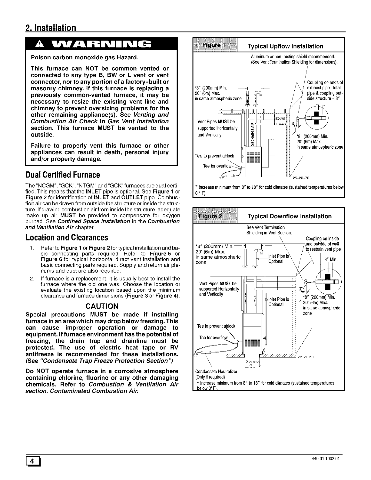
DualCertifiedFurnace
The"NCGM", "GCK","NTGM"and"GCK"furnacesare dual certi-
fied. Thismeansthatthe INLET pipe isoptional.See Figure 1 or
Figure 2 for identificationof INLET and OUTLETpipe. Combus-
tion aircan bedrawnfrom outside thestructureorinsidethe struc-
ture. Ifdrawingcombustion airfrom insidethe structure, adequate
make up air MUST be provided to compensate for oxygen
burned. See Confined Space Installation in the Combustion
and Ventilation Air chapter.
Locationand Clearances
1. Refer to Figure 1or Figure 2 for typical installation and ba-
sic connecting parts required. Refer to Figure5 or
Figure 6 for typical horizontal direct vent installation and
basic connecting parts required. Supply and return air ple-
nums and duct are also required.
2. If furnace is a replacement, it is usually best to install the
furnace where the old one was. Choose the location or
evaluate the existing location based upon the minimum
clearance and furnace dimensions (Figure 3 or Figure 4).
CAUTION
Special precautions MUST be made if installing
furnace in an area which may drop below freezing. This
can cause improper operation or damage to
equipment. If furnace environment has the potential of
freezing, the drain trap and drainline must be
protected. The use of electric heat tape or RV
antifreeze is recommended for these installations.
(See "Condensate Trap Freeze Protection Section ")
Do NOT operate furnace in a corrosive atmosphere
containing chlorine, fluorine or any other damaging
chemicals. Refer to Combustion & Ventilation Air
section, Contaminated Combustion Air.
25-20-70
* Increaseminimumfrom8" to 18" forcoldclimates(sustainedtemperaturesbelow
0 ° F).
Typical Downflow Installation
See VentTermination
Shielding inVent _ction.
*8" (200mm) Min._ _
20' (6m)Max. _> ___ InletPip
Zoiqe
in same atmospheric _ Optional\
supportedHorizontally
andVertically
\
is
Couplingon inside
_re d outsideof wall
strainventpipe
"8"(200mm)Min.
/ 20' (6m)Max.
insameatmospheric
zone
Teeto preventairlock
\
CondensateNeutralizer
(Onlyifrequired)
*Increaseminimumfrom8"to18"forcoldclimates(sustainedtemperatures
belowO°F}.
[_ 44001 100201
Page 5
iiiiiii!!i!liiiii/l;i!iiiii/!iiiiiiii!liil;iii/iiiiiiiiii'ii!iii!!///!i
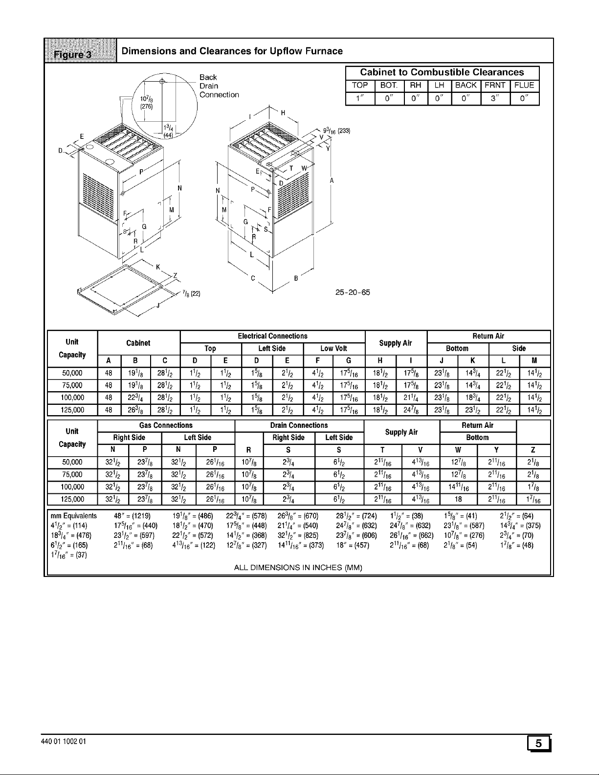
!! !!!!OimensionsandC,earances,orUp.owFurnace
__ Back Cabinet to
Drain TOPIBOT"I
Connection 1 ' 0'
"""'-_ 718 (22) _' _ 25-20-65
Combustible Clearances
i I'C IF= TI 'OE0' 0' 0' 3' 0"
Unit
Capacity
50,000
75,000
100,000
125,000
Unit
Capacity
50,000
75,000
100,000
125,000
turnEquivalents 48" = (1219) 191/8" = (486) 228/4"= (578) 263/8" = (670) 281/2"= (724) 11/2"= (38) 15/8" = (41) 21/2"= (64)
41/2"= (114) t75/16" = (440) 181/2"= (470) 175/8"= (448) 211/4"=(540) 247/8"= (632) 247t8" = (632) 231/8" =(587) t43/4" = (375)
t83/4" = (476) 231/2"=(597) 221/2" = (572) 141/2" = (368) 321/2"= (825) 237/8"= (606) 261/16"=(662) 107/8" = (276) 23/4" = (70)
61/2" = (165) 211/16"=(68) 4131_6"= (122) 127/8" = (327) 1411/16"= (373) 18" = (457) 2_1/16"= (68) 21/8" = (54) 17/8"= (48)
t7/16" = (37)
Cabinet
B
48 191t8 281_
48 19118 281_
48 223/4 281_
48 26_8 281_
GasConnections
RightSide LeftSide
N P N P R
321/2 237t8 321/2 261/16 107/8
321/2 237/8 321/2 261/16 107/8
321/2 237t8 321/2 261/16 107/8
321/2 237t8 321/2 261/16 107/8
Top LeftSide LowVolt
D E D E F G
11/2 11/2 t5/8 21/2 41/2 17_16
11/2 11/2 t5/8 21/2 41/2 17_16
11/2 11/2 t5/8 21/2 41/2 17_16
11/2 11/2 t518 21/2 41/2 17_16
ElectricalConnections
DrainConnections
RightSide LeftSide
S S
23/4 61t2
23/4 61/2
23/4 61/2
23/4 61/2
ALL DIMENSIONS IN INCHES (MM)
SupplyAir
H I
18112 175/8
181/2 175/8
181/2 211/4
181/2 247/8
SupplyAir
T V
211116 413/16
211/16 413/16
211/16 413/16
211/16 413/16
J K L
231/8 143/4 221/2 t41t2
231f8 143/4 221/2 t41/2
231/8 183/4 221/2 t41t2
231/8 231/2 221/2 t41t2
ReturnAir
Bottom Side
M
ReturnAir
Bottom
W Y Z
127/8 211/16 21/8
127/8 211/16 21/8
t411116 211/16 17/8
18 211/16 17/16
440 01 100201 [_
Page 6
iiiiiiiiiiiiiiiiiiiiiiiiiiiiiiiiiiiiiiiiiiiiiiiiiiiiiiiiiiiiiiiiiiiiiiiiiiiiiiiiiiiiiiiiiiiiiiiiiiiiiiiiiiiiiiiiiiiiiiiiiiii
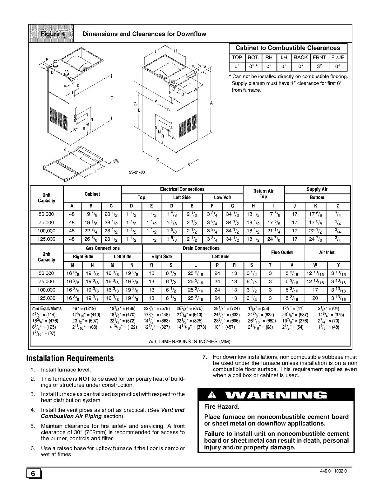
Dimensions and Clearances for Downflow
¥ v
Cabinet to Combustible Clearances
TOP BOT. RH LH BACK FRNT FLUE
0" 0"* 0" 0" 0" 3" O"
* Can not be installed directly on combustible flooring.
Supp _'plenum must have 1" clearance for first 6'
from furnace.
_ 33/4
c B/
25-21-83 _"/
Unit
Capacity
50,000
75,000
100,000
125,000
Unit
Capacity
50,000
75,000
100,000
125,000
ram Equivalents 48" = (1219) 191/8" = (486) 223/4" = (578) 263/8" = (670) 281/2" = (724) 11/2" = (38) 15/8" = (41) 21/2" = (64)
41/2" = (114) t75/16" = (440) 181/2" = (470) 175/8" = (448) 211/4" =(540) 247/8" = (632) 247t8" = (632) 23118" = (587) t43/4 " = (375)
t83/4" = (476) 231/2" = (597) 221/2" = (572) 141/2" = (368) 321/2 ', = (825) 237/8" = (606) 261/16" = (662) 107/8" = (276) 23/4" = (70)
61/2" = (165) 211/16" = (68) 413/16" = (122) 127/8" = (327) 1411116"= (373) 18" = (457) 211t16" = (68) 21/8" = (54) 17/8" = (48)
t7/16" = (37)
Cabinet
A B C
48 191/8 28112
48 191/8 28112
48 223/4 28112
48 263/8 28112
Gas Connections
Right Side LeftSide
M N M N
163/8 193/8 163/8 t93/8
163/8 193/8 163/8 t93/8
163/8 193/8 163/8 t93/8
163/8 193/8 163/8 t93/8
D E D E F G
11/2 11/2 1 5/8 2 1/2 3 3/4 341/2
1 1/2 1 1/2 1 5/8 2 1/2 3 3/4 34 1/2
1 1/2 1 1/2 1 5/8 2 1/2 3 3/4 34 1/2
1 1/2 1 1/2 1 5/8 2 1/2 3 3/4 34 1/2
Top LeftSide LowVolt
ElectricalConnections
DrainConnections
RightSide LeftSide
R S L P R S
13 61& 25 _18 24 13 61&
13 61& 25 _18 24 13 61&
13 61_ 25 _16 24 13 61_
13 61_ 25 _16 24 13 61_
ALL DIMENSIONS IN INCHES (MM)
ReturnAir
Top
H I J
181/2 175/8 17
181/2 175/8 17
181/2 21 1/4 17
181/2 247/8 17
FlueOutlet
T
3
53/16
3
53/16
3
53/16
3
53/16
SupplyAir
Bottom
K Z
t75_ 3_
t75_ 3_
2216 3_
247_ 3_
AirInlet
v
W
1213/16
1213/16
17
20
Y
3 13/16
3 13/16
3 13/16
3 13/16
7.
InstallationRequirements
1. Install furnace level.
2. This furnace is NOT to be used for temporary heat of build-
For downflow installations, non combustible subbase must
be used under the furnace unless installation is on a non
combustible floor surface. This requirement applies even
when a coil box or cabinet is used.
ings or structures under construction.
3. Install furnace as centralized as practical with respect to the
heat distribution system.
4. Install the vent pipes as short as practical. (See Vent and
Combustion Air Piping section).
5. Maintain clearance for fire safety and servicing. A front
clearance of 30" (762mm) is recommended for access to
the burner, controls and filter.
6. Use a raised base for upflow furnace if the floor is damp or
Fire Hazard.
Place furnace on noncombustible cement board
or sheet metal on downflow applications.
Failure to install unit on noncombustible cement
board or sheet metal can result in death, personal
injury and/or property damage.
wet at times.
[_ 44001100201
Page 7
8. For horizontal installations, line contact is permissible only
between lines formed by intersection of back and two sides
of furnace jacket, and building joists, studs or framing.
9. Residential garage installations require:
• Burners and ignition sources installed at least
18" (457mm) above the floor.
• Located or physically protected from possible damage by a
vehicle.
10. Local codes may require a drain pan under the entire fur-
nace and condensate trap when the furnace is installed in
attic application.
HorizontalFurnaceInstallation
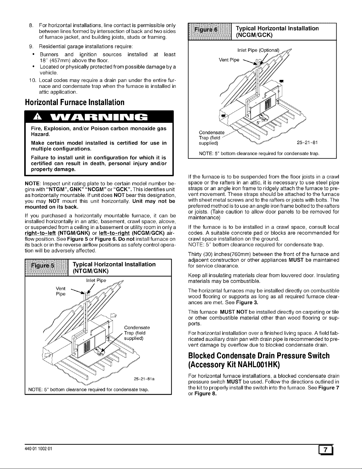
Typical Horizontal Installation
(NCGM/GCK)
Inlet Pipe (Optional)
Vent Pipe
Fire, Explosion, and/or Poison carbon monoxide gas
Hazard.
Make certain model installed is certified for use in
multiple configurations.
Failure to install unit in configuration for which it is
certified can result in death, personal injury and/or
property damage.
NOTE: Inspect unit rating plate to be certain model number be-
gins with "NTGM", GNK" "NCGM" or "GCK'. This identifies unit
as horizontally mountable. Ifunit does NOT bear this designation,
you may NOT mount this unit horizontally. Unit may not be
mounted on its back.
If you purchased a horizontally mountable furnace, it can be
installed horizontally in an attic, basement, crawl space, alcove,
or suspended from a ceiling in a basement or utility room in only a
right-to-left (NTGM/GNK) or left-to-right (NCGM/GCK) air-
flow position. See Figure 5 or Figure 6. Do not install furnace on
its back or in the reverse airflow positions as safety control opera-
tion will be adversely affected.
Typical Horizontal Installation
(NTGM/GNK)
Inlet Pipe
Vent
Pipe
Condensate
Trap (field
supplied)
Condensate
Trap (field
supplied)
NOTE: 5" bottom clearance required for condensate trap.
If the furnace is to be suspended from the floor joists in a crawl
space or the rafters in an attic, it is necessary to use steel pipe
straps or an angle iron frame to ridgely attach the furnace to pre-
vent movement. These straps should be attached to the furnace
with sheet metal screws and to the rafters or joists with bolts. The
preferred method is to use an angle iron frame bolted to the rafters
or joists. (Take caution to allow door panels to be removed for
maintenance)
If the furnace is to be installed in a crawl space, consult local
codes. A suitable concrete pad or blocks are recommended for
crawl space installation on the ground.
NOTE: 5" bottom clearance required for condensate trap.
Thirty (30) inches(760mm) between the front of the furnace and
adjacent construction or other appliances MUST be maintained
for service clearance.
Keep all insulating materials clear from Iouvered door. Insulating
materials may be combustible.
The horizontal furnaces may be installed directly on combustible
wood flooring or supports as long as all required furnace clear-
ances are met. See Figure 3.
This furnace MUST NOT be installed directly on carpeting or tile
or other combustible material other than wood flooring or sup-
ports.
For horizontal installation over a finished living space. A field fab-
ricated auxiliary drain pan with drain pipe is recommended to pre-
vent damage by overflow due to blocked condensate drain.
25-21-81
BlockedCondensateDrainPressureSwitch
25-21-81 a
NOTE: 5" bottom clearance required for condensate trap.
440 01 100201
(AccessoryKitNAHL001HK)
For horizontal furnace installations, a blocked condensate drain
pressure switch MUST be used. Follow the directions outlined in
the kit to properly install the switch into the furnace. See Figure 7
or Figure 8.
Page 8
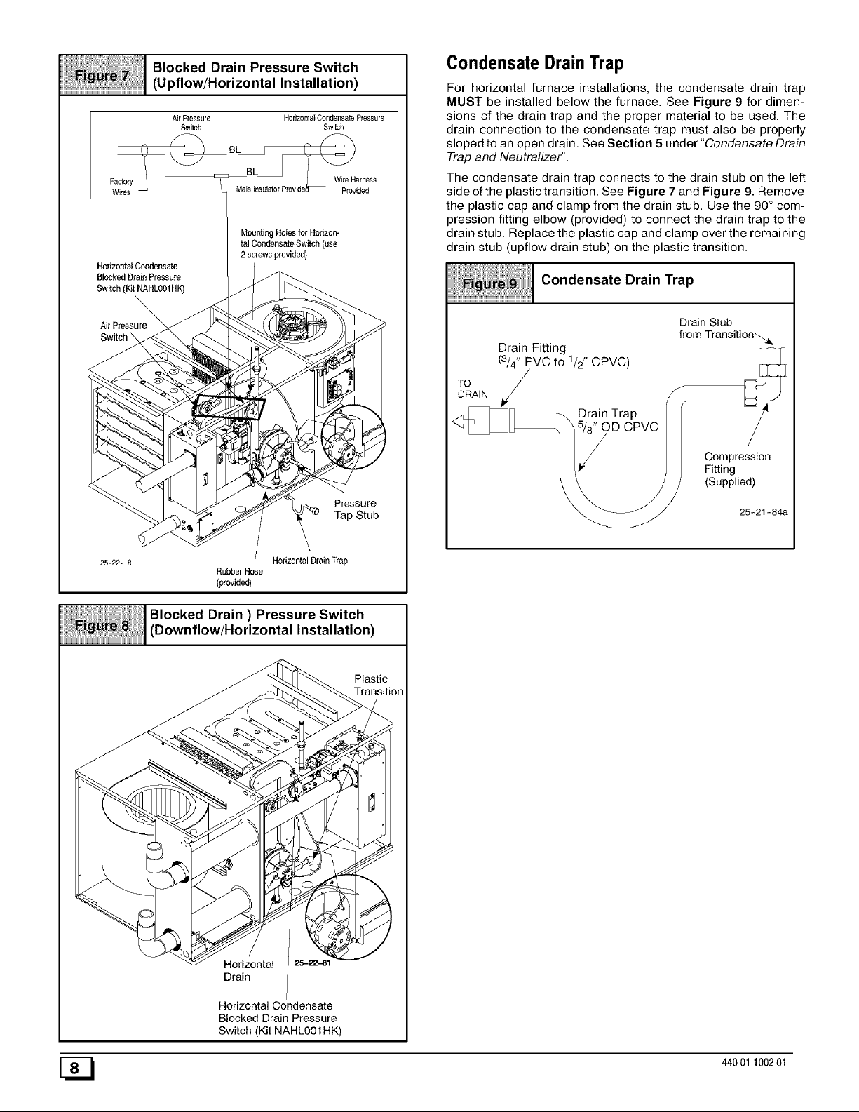
Blocked Drain Pressure Switch
(Upflow/Horizontal Installation)
Air Pressure Horn.offal Condensate Pressure
Switch Switch
W,res Mal_l_Prov_e_ V_ip_Hiadr_ss
MountingHolesforHorizon-
talCondensateSwitch (use
HorizontaJ Condensate
BlockedDrain Pressure
Switch(Kit NAHLO01HK)
Air Pressure_
2 screwsprovided)
CondensateDrainTrap
For horizontal furnace installations, the condensate drain trap
MUST be installed below the furnace. See Figure 9 for dimen-
sions of the drain trap and the proper material to be used. The
drain connection to the condensate trap must also be properly
sloped to an open drain. See Section 5 under "Condensate Drain
Trap and Neutralizer".
The condensate drain trap connects to the drain stub on the left
side of the plastic transition. See Figure 7 and Figure 9. Remove
the plastic cap and clamp from the drain stub. Use the 90° com-
pression fitting elbow (provided) to connect the drain trap to the
drain stub. Replace the plastic cap and clamp over the remaining
drain stub (upflow drain stub) on the plastic transition.
Condensate Drain Trap
Drain Stub
Drain Fitting
(3/4" PVC to 1/2" CPVC)
from Transition'_.&
25-22-18
Y
/ T ps,ub
RubberHsse
(provided)
Blocked Drain ) Pressure Switch
HorizontalDrainTrap
Installation)
Plastic
Transition
DRAIN
,/
Drain Trap
OD CPVC
S
Compression
Fitting
(Supplied)
25-21-84a
Horizontal
Drain
Horizontal Condensate
Blocked Drain Pressure
Switch (Kit NAHLOO1HK)
[_ 44001 100201
Page 9
3. Combustion&VentilationAir
Poison carbon monoxide gas Hazard.
Use methods described here to provide combustion
and ventilation air.
Failure to provide adequate combustion and ven-
tilation air can result in death and/or personal injury.
Ventingand CombustionAir Check
NOTE: The following information is supplied to allow the installer
to make adjustments to the setup of existing appliances, IF
REQUIRED, based on good trade practices, local codes, and
good judgement of the installer. Manufacturer does NOT take re-
sponsibility for modifications made to existing equipment.
NOTE: If this installation removes an existing furnace from a
venting system serving one or more other appliances, and to
make sure there is adequate combustion air for all appliances,
MAKE THE FOLLOWING CHECK.
1. Seal any unused openings in the venting system.
2. Visually inspect the venting system for proper size and hor-
izontal pitch to ensure there is no blockage or restriction,
leakage, corrosion or other deficiencies which could cause
an unsafe condition.
3. Insofar as is practical, close all doors and windows and all
doors between the space inwhich the appliance(s) remain-
ing connected to the venting system are located and other
spaces of the building.
4. Turn on clothes dryers and any appliance not connected to
the venting system. Turn on any exhaust fans, such as
range hoods and bathroom exhausts, so they will operate
at maximum speed. Do not operate a summer exhaust fan.
Close fireplace dampers.
5. Follow the lighting instructions for each appliance being in-
spected. Adjust thermostat so appliance(s) will operate
continuously.
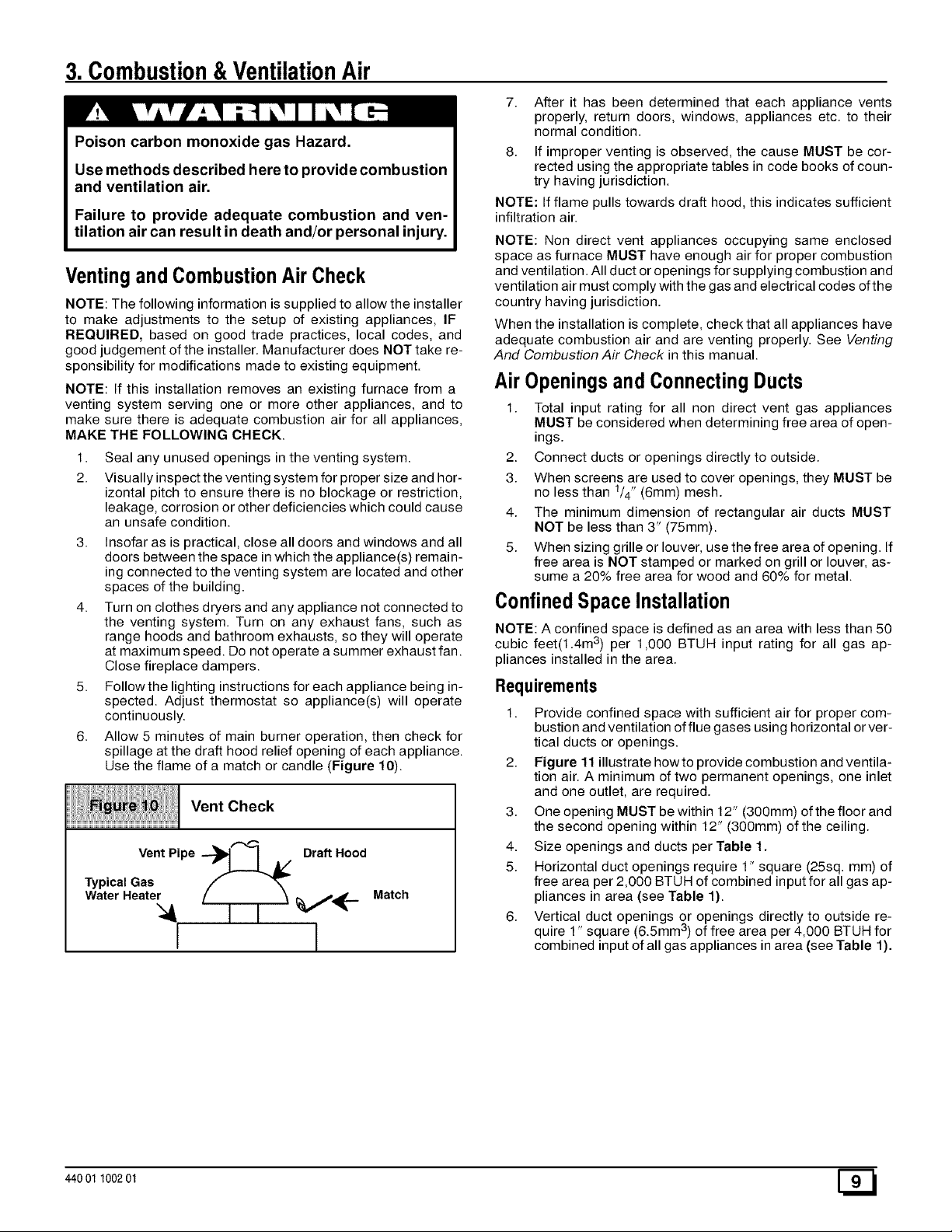
6. Allow 5 minutes of main burner operation, then check for
spillage at the draft hood relief opening of each appliance.
Use the flame of a match or candle (Figure 10).
Vent Check
Vent Pipe ---_t I A/ Draft Hood
Typical Gas
Water Heate_;_l / ] i _ V'_'-
Match
7. After it has been determined that each appliance vents
properly, return doors, windows, appliances etc. to their
normal condition.
8. If improper venting is observed, the cause MUST be cor-
rected using the appropriate tables in code books of coun-
try having jurisdiction.
NOTE: If flame pulls towards draft hood, this indicates sufficient
infiltration air.
NOTE: Non direct vent appliances occupying same enclosed
space as furnace MUST have enough air for proper combustion
and ventilation. All duct or openings for supplying combustion and
ventilation air must comply with the gas and electrical codes ofthe
country having jurisdiction.
When the installation is complete, check that all appliances have
adequate combustion air and are venting properly. See Venting
And Combustion Air Check in this manual.
Air Openingsand ConnectingDucts
1. Total input rating for all non direct vent gas appliances
MUST be considered when determining free area of open-
ings.
2. Connect ducts or openings directly to outside.
3. When screens are used to cover openings, they MUST be
no less than 1/4" (6mm) mesh.
4. The minimum dimension of rectangular air ducts MUST
NOT be less than 3" (75mm).
5. When sizing grille or louver, use the free area of opening. If
free area is NOT stamped or marked on grill or louver, as-
sume a 20% free area for wood and 60% for metal.
ConfinedSpaceInstallation
NOTE: A confined space is defined as an area with less than 50
cubic feet(1.4m 3) per 1,000 BTUH input rating for all gas ap-
pliances installed in the area.
Requirements
1. Provide confined space with sufficient air for proper com-
bustion and ventilation of flue gases using horizontal or ver-
tical ducts or openings.
2. Figure 11 illustrate howto provide combustion and ventila-
tion air. A minimum of two permanent openings, one inlet
and one outlet, are required.
3. One opening MUST be within 12" (300mm) of the floor and
the second opening within 12" (300mm) of the ceiling.
4. Size openings and ducts per Table 1.
5. Horizontal duct openings require 1" square (25sq. mm) of
free area per 2,000 BTUH of combined input for all gas ap-
pliances in area (see Table 1).
6. Vertical duct openings or openings directly to outside re-
quire 1" square (6.5mm 3)of free area per 4,000 BTUH for
combined input of all gas appliances in area (see Table 1).
440 01 100201 [_
Page 10
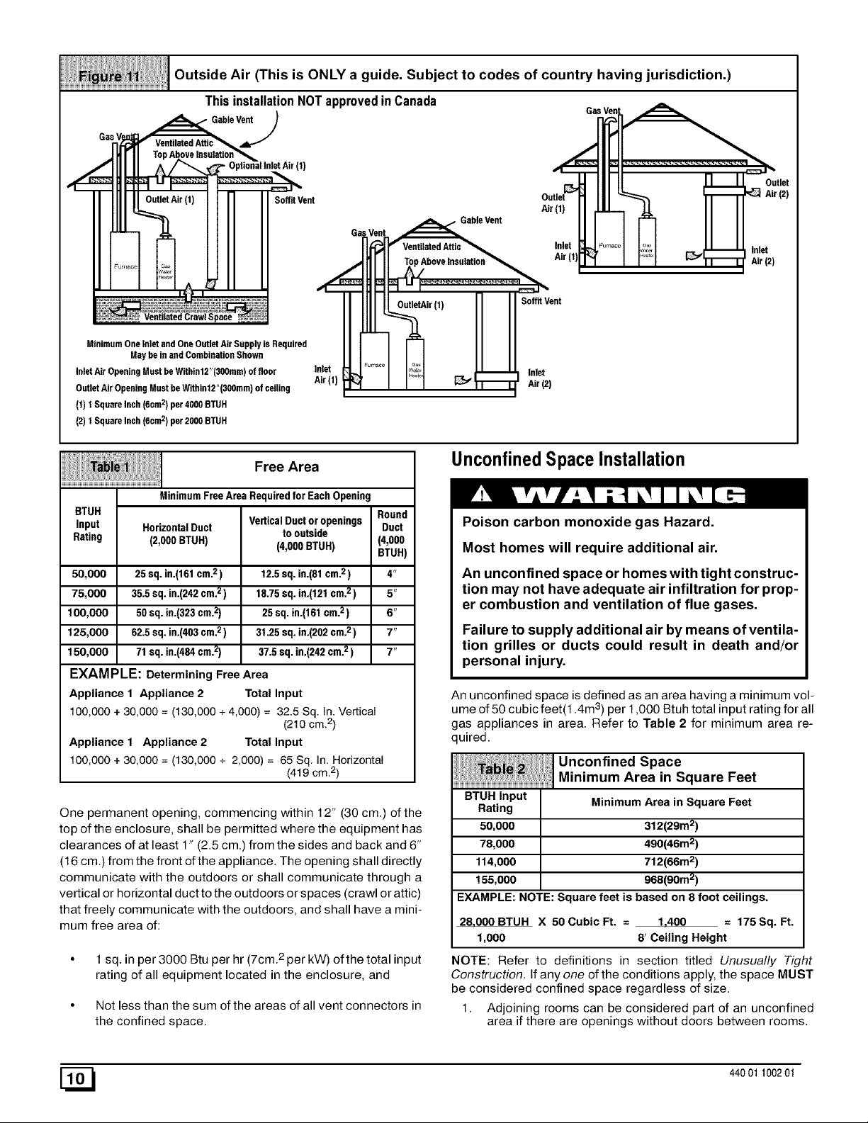
Outside Air (This is ONLY a guide. Subject to codes of country having jurisdiction.)
This installation NOT approved in Canada
Gas V
- GableVe_
(1)
SoffitVent
GasVent
MinimumOneInletand OneOutletAir Supplyis Required
InletAir OpeningMustbeWithin12"(300mm)offloor
OutletAir OpeningMustbeWithin12"(300mm)ofceiling
(1) 1 SquareInch(6cm2) per4000BTUH
(2) 1 SquareInch(6cm2) per2000BTUH
Maybe in andCombinationShown
Inlet
Air(1
Free Area
MinimumFree AreaRequiredfor EachOpening
BTUH
input HorizontalDuct
Rating (2,000 BTUH)
50,000 25 sq. in.(161cm.2)
75,000 35.5 sq. in.(242cm.2)
100,000 50 sq. in.(323cm.2)
125,000 62.5sq. in.(403cm.2)
150,000 71 sq. in.(484cm.2)
EXAMPLE: Determining Free Area
Appliance 1 Appliance 2 Total Input
100,000 + 30,000 = (130,000 + 4,000) = 32.5 Sq. In. Vertical
Appliance 1 Appliance 2 Total Input
100,000 + 30,000 = (130,000 + 2,000) = 65 Sq. In. Horizontal
One permanent opening, commencing within 12" (30 cm.) of the
top of the enclosure, shall be permitted where the equipment has
clearances of at least 1" (2.5 cm.) from the sides and back and 6"
(16 cm.) from the front of the appliance. The opening shall directly
communicate with the outdoors or shall communicate through a
vertical or horizontal duct tothe outdoors or spaces (crawl or attic)
that freely communicate with the outdoors, and shall have a mini-
mum free area of:
1 sq. in per 3000 Btu per hr (7cm. 2 per kW) ofthe total input
rating of all equipment located in the enclosure, and
Not less than the sum of the areas of all vent connectors in
the confined space.
VerticalDuctoropenings Round
to outside Duct
(4,000BTUR) (4,000
12.5sq. in.(81cm.2) 4"
18.75 sq.in.(121cm.2) 5"
25 sq.in.(161cm.2) 6"
31.25 sq.in.(202cm.2) 7"
37.5sq. in.(242cm.2) 7"
(210 cm.2)
(419 cm 2)
BTUH)
GableVent
Air (1)
Inlet
Air(1)
Soft, Vent
Inlet
Air (2)
UnconfinedSpaceInstallation
Poison carbon monoxide gas Hazard.
Most homes will require additional air.
An unconfined space or homes with tight construc-
tion may not have adequate air infiltration for prop-
er combustion and ventilation of flue gases.
Failure to supply additional air by means of ventila-
tion grilles or ducts could result in death and/or
personal injury.
An unconfined space is defined as an area having a minimum vol-
ume of 50 cubic feet(1.4m 3) per 1,000 Btuh total in put rating for all
gas appliances in area. Refer to Table 2 for minimum area re-
quired.
_ _!i ii _iiJUnconfined Space
BTUH Input
Rating Minimum Area in Square Feet
50,000 312(29m2)
78,000 490(46m2)
114,000 712(66m2)
155,000 968(90m2)
EXAMPLE: NOTE:Square feet is based on 8 foot ceilings.
28,000BTUH X 50CubicFt. = 1,400 = 175Sq. Ft.
1,000 8' Ceiling Height
NOTE: Refer to definitions in section titled Unusually Tight
Construction. If any one of the conditions apply, the space MUST
be considered confined space regardless of size.
1. Adjoining rooms can be considered part of an unconfined
area if there are openings without doors between rooms.
Minimum Area in Square Feet
[_ 44001 100201
Page 11

2.
An attic or crawlspace may be considered an unconfined
space provided there are adequate ventilation openings di-
rectly to outdoors. Openings MUST remain open and NOT
have any means of being closed off. Ventilation openings to
outdoors MUST be at least 1"square (25mm 2) of free area
per 4,000 BTUH of total input rating for all gas appliances in
area.
3.
Install air intake a minimum of 12" (300mm) above maxi-
mum snow level and clear of any obstruction. Duct or ven-
tilation opening requires one square inch of free area per
4,000 BTUH of total input rating for all gas appliances in
area.
4.
Air inlet MUST be screened with not less than 1/4" (6mm)
mesh screen.
UnusuallyTight Construction
In unconfined spaces, infiltration may be adequate to provide air
for combustion, ventilation and dilution of flue gases. However, in
buildings with unusually tight construction, additional air MUST
4.VentandCombustionAir Piping
Poison carbon monoxide gas, fire and explo-
sion hazard.
Read and follow all instructions in this section.
Failure to properly vent this furnace can result in
death, personal injury and/or property damage.
DualCertifiedFurnace
This furnace is certified as a category IV appliance and is dual
certified as a direct vent furnace using outside air for combustion
or it can use air from inside the structure for combustion. The IN-
LET air pipe is optional. If combustion air comes from inside the
structure, adequate make up air MUST be provided to compen-
sate for oxygen burned. See Confined Space Installation in the
Combustion and Ventilation Air chapter. If combustion air is
drawn from outside the structure, it MUST be taken from the same
atmospheric pressure zone as the vent pipe.
ContaminatedCombustionAir
Installations in certain areas or types of structures will increase
the exposure to chemicals or halogens that may harm the fur-
nace.
The following areas or types of structures may contain or have ex-
posure to the substances listed below. The installation must be
evaluated carefully as it may be necessary to provide outside air
for combustion.
• Commercial buildings.
• Buildings with indoor pools.
• Furnaces installed in laundry rooms.
• Furnaces installed in hobby or craft rooms.
• Furnaces installed near chemical storage areas.
• Permanent wave solutions for hair.
• Chlorinated waxes and cleaners.
• Chlorine based swimming pool chemicals.
• Water softening chemicals.
• De-icing salts or chemicals.
be provided using the methods described in section titled Con-
fined Space Installation:
Unusually tight construction is defined as: Construction with
1. Walls and ceilings exposed to the outside have a continu-
ous, sealed vapor barrier. Openings are gasketed or
sealed and
2. Doors and openable windows are weather stripped and
3. Other openings are caulked or sealed. These include joints
around window and door frames, between sole plates and
floors, between wall-ceiling joints, between wall panels, at
penetrations for plumbing, electrical and gas lines, etc.
VentilationAir
Some provincial codes and local municipalities require ventilation
or make-up air be brought into the conditioned space as replace-
ment air. Whichever method is used, the mixed return air temper-
ature across the heat exchanger MUST not fall below 60°F (15° c)
or flue gases will condense in the heat exchanger. This will short-
en the life of the heat exchanger and possibly void your warranty.
• Carbon tetrachloride.
• Halogen type refrigerants.
• Cleaning solvents (such as perchloroethylene).
• Printing inks, paint removers, varnishes, etc.
• Hydrochloric acid.
• Sulfuric Acid.
• Solvent cements and glues.
• Antistatic fabric softeners for clothes dryers.
• Masonry acid washing materials.
Vent and CombustionAir PipingGuidelines
NOTE: All vent piping MUST be installed in compliance with local
codes or ordinances, these instructions, good trade practices,
and codes of country having jurisdiction.
1. Determine the best routing and termination for the vent
pipe and air inlet pipe by referring to all of the instructions
and guidelines in this Section.
2. Determine the size required for the vent pipe and air inlet
pipe.
3. Loosely assemble all venting parts without adhesive (pipe
joint cement) for correct fit before final assembly.
4. Use of vertical piping is preferred because there will be
some moisture in the flue gases that may condense as it
leaves the vent pipe (See Special Instruction For Horizon-
tal Vents).
5. The vent MUST exit the furnace at the top left side.
6. The vertical vent pipe MUST be supported so that no
weight is allowed to rest on the combustion blower.
7. Exhaust vent piping or air inlet piping diameter MUST NOT
be reduced.
8. All exhaust vent piping from the furnace to termination
MUST slope upwards, away from furnace, a minimum of
1/4" per foot of run (6mm per 300mm).
9. Use DWV type long radius elbows whenever possible, as
they provide for the minimum slope on horizontal runs and
they provide less resistance in the vent system. If DWV el-
bows cannot be used, use two, 45 degree elbows when
possible. On horizontal runs the elbows can be slightly mis-
aligned to provide the correct slope.
440 01 100201 [_
Page 12

10. All horizontal pipe runs MUST be supported at least every
five feet with galvanized strap or other rust resistant materi-
al. NO sags or dips are permitted.
11. All vertical pipe runs MUST be supported every six feet
where accessible.
12. The maximum pipe length is 40' (12m) total in the inlet or
outlet side of the system. Up to five, 90 ° elbows can be
used on the inlet or the outlet. If more than five elbows are
required, reduce the length of both the inlet and exhaust
pipes 5' (1.5m) for each additional elbow used. (See Vent
Tables).
13. The minimum pipe run length is 2' (.6m).
14. The piping can be run in the same chase or adjacent to sup-
ply or vent pipe for water supply or waste plumbing. It can
also be run in the same chase with a vent from another 90+
furnace.
NOTE: In NO case can the piping be run in a chase where
temperatures can exceed 140° F. or where radiated heat
from adjacent surfaces would exceed 140° F.
15. The vent outlet MUST be installed to terminate in the same
atmospheric pressure zone as the combustion air inlet.
16. The vent system can be installed in an existing unused
chimney provided that:
• Both the exhaust vent and air intake run the length of the
chimney.
• No other gas fired appliance or fireplace (solid fuel) is
vented into the chimney.
• The top of the chimney MUST be sealed flush or crowned
up to seal against rain or melting snow so ONLY the piping
protrudes.
• The termination clearances shown in Figure 12 are main-
tained.
17. Horizontal furnace applications with vertical vents requir-
ing vent diameter increaser fittings must have increaser fit-
tings installed in vertical portion of the vent after a 2" elbow
turns upward. Condensate will be trapped in the vent if the
vent diameter is increased prior to having an elbow turned
upward. This could cause nuisance tripping of the pressure
switch. (This does not apply to horizontal venting.)
Piping Insulation Guidelines
NOTE: In general, chimneys on an outside wall and attics are ex-
posed to cold conditions which can cause the vent pipe to sweat
from condensation. This can lead to moisture damage to living
spaces. It is highly recommended that piping in these cases be
insulated to insure proper protection from condensation damage.
Use closed cell, neoprene insulation or equivalent. If Fiberglass
or equivalent insulation is used it must have a vapor barrier. Use R
values of 7 up to 10', R-11 if exposure exceeds 10L If Fiberglass
insulation is used, exterior to the structure, the pipe MUST be
boxed in and sealed against moisture.
1. Insulate pipe when the exhaust vent passes through an un-
conditioned space or raceway.
2.
If situations require pipe to be run on the exterior wall to
reach a suitable termination point, it MUST be properly in-
sulated.
3. If it is necessary to insulate piping when an inactive chim-
ney is used as a chase, the top of the chimney MUST be
sealed flush or crowned up to seal against rain or melting
snow so ONLY the piping protrudes.
4. When the vent or combustion air pipe height above the roof
exceeds 30" (760mm), or if an exterior vertical riser is used
on a horizontal vent to get above snow levels, the exterior
portion MUST be insulated.
5. When combustion air inlet piping is installed above a sus-
pended ceiling, the pipe MUST be insulated with moisture
resistant insulation such as Armaflex or other equivalent
type of insulation.
6. Insulate combustion air inlet piping when run in warm, hu-
mid spaces such as basements.
SizingCombustionAir andVent Pipe
1. Consult Table 4 to select the proper diameter exhaust and
combustion air piping. Exhaust and combustion air piping
is sized for each furnace Btuh size based on total lineal vent
length (on inlet or outlet side), and number of 90 ° elbows
required.
1. Single Pipe Installation-If installing as a non-direct vent
appliance, (single outlet pipe and no inlet pipe) refer to
Table 3. The table shows the maximum number of elbows
allowed with any given pipe diameter and length of run.
2. Double Pipe Installation-If installing as a direct-vent ap-
pliance, consult Table 4 to select the proper diameter ex-
haust and combustion air piping. Exhaust and combustion
air piping is sized for each furnace Btuh size based on total
lineal vent length (on inlet or outlet side), and number of 90°
elbows required.
2. Use of Elbows-Two 45 ° elbows can be substituted for one
90° elbow. The elbow or elbows used for vent termination
outside the structure ARE counted, including elbows need-
ed to bring termination above expected snow levels.
EXAMPLE: Refer to, 75,000 Btuh Furnace, Table 4.
• Avent system uses 25' of Inlet pipe and 24' of Outlet pipe. Use
the maximum length found in your system, so 25' is the length to
use in these tables.
• There are 4 elbows on the Outlet and 2 elbows on the Inlet. Use
the 4 elbows row because that is the maximum number of elbows
on any one side (Inlet or Exhaust).
• In this example, combinations C or F are allowed. Using the
legend at the bottom of the table, combination C is 3" Inlet with a
21/2'' Exhaust. Combination F is a 3" Inlet with a 3" Exhaust. Ei-
ther combination is allowed together, but they can NOT be mixed.
In other words, part ofa C combination can NOT be used with part
of an F combination just because they are listed together in the
same block.
[_ 44001 100201
Page 13

Pipe Diameter Table
i_ I Pipe Diameter Table
Single Piping ONLY
50,000 & 75,000 Btuh Furnaces
MaxNo.0f Feet of Pipe*
Elbows in
onosi°e 00110141151012024125201303413540
UP TO 5 All combinations use "A" a 2" Exhaust
100,000 Btuh Furnace
Feet of Pipe*
0-9 10-14 15-19 20-24 25-29 30-34 35-40
1 A A A A A A B,C
2 A A A A A B,C B,C
3 A A A A B,C B,C B,C
4 A A A B,C B,C B,C B,C
5 A A B,C B,C B,C B,C B,C
125,000 Btuh Furnace
Feet of Pi >e*
0-9 10-14 15-19 20-24 25-29 30-34 35-40
1 A A B,C B,C B,C B,C C
2 A B,C B,C B,C B,C C C
3 B,C B,C B,C B,C C C C
4 B,C B,C B,C C C C C
5 B,C B,C C C C C C
Possible combination legend:
A = 2" Exhaust
B = 21/2" Exhaust
C = 3" Exhaust
Elbows are DWV Long Radius Type for 2" and 3" vents.
Schedule 40 (sharp radius) for 21/2 `'
If more than five elbows are required, reduce the length of
both the inlet and exhaust pipes 5' (1.5m) for each additional
elbow used.
I OTE: It is allowable to use larger diameter pipe and fitting thanshown in the tables but not smaller diameters than shown.
MaxNo.Of Feet of Pipe*
Elbowsin
0neSide_ 0-9 110-14115-19120-24125-29130-34135-40
UP TO 5 All combinations use "A" a 2" Exhaust and 2" Air
0-9 10-14 15-19 20-24 25-29 30-34 35-40
1 A A A A D,B E,B E,B
2 A A A D,B E,B E,B C,F
3 A A D,B E,B E,B C,F C,F
4 A D,B E,B E,B C,F C,F C,F
5 D,B E,B E,B C,F C,F C,F C,F
0-9 10-14 15-19 20-24 25-29 30-34 35-40
1 A A A D,B E,B E,B C,F
2 A A D,B E,B E,F C,F C,F
3 A D,B E,B E,F C,F C,F C,F
4 D,B E,B E,F C,F C,F C,F C,F
5 D,B E,F C,F C,F C,F C,F C,F
0-9110-14115-10120-24125-20130-34135-40
UP TO 5 All combinations use "F" a 3" Exhaust and 3" Air
Possible combination legend:
A = 2" Inlet with a 2" Exhaust
B = 3" Inlet with a 2" Exhaust
C = 3" Inlet with a 21/2" Exhaust
D = 21/2" Inlet with a 2" Exhaust
E = 21/2`'Inlet with a 21/2 " Exhaust
F = 3" Inlet with a 3" Exhaust
Elbows are DWV Long Radius Type for 2" and 3" vents.
Schedule 40 (sharp radius) for 21/2"
- Signifies the maximum number of elbows, including the
termination elbow(s), on any one part of the system. Exam-
ple: 4 elbows on the exhaust and 5 elbows on the inlet would
use the chart showing 5 elbows, because 5 is the maximum
number on any one side.
If more than five elbows are required, reduce the length of
both the inlet and exhaust pipes 5' (1.5m) for each additional
elbow used.
* Feet of pipe is whichever pipe run is the longest, either inlet
or outlet side.
For "Concentric Termination Kit" Venting table, see
"Section 10" in this manual,
Dual Piping ONLY
50,000 Btuh Furnaces
Inlet Pipe
75,000 Btuh Furnace
Feet of Pipe*
100,000 Btuh Furnace
Feet of Pi )e*
125,000 Btuh Furnace
Feet of Pipe*
Inlet Pipe
Vent Termination Clearances
Poison carbon monoxide gas, fire and explo-
sion hazard.
Inlet and outlet pipes may NOT be vented
directly above each other.
Failure to properly vent this furnace can result in
death, personal injury and/or property damage.
440 01 100201 [_
Page 14

1. Determine termination locations based on clearances spe-
cified in following steps and as shown in Figure 12,
Figure 16, Figure 17, Figure 18.
For "Concentric Termination Kit" clearances, see Figure 45,
Figure 46, Figure 47, Figure 48 and Figure 49 in "Section 10"
in this manual.
2. The vent termination must be located at least 12" (300mm)
above ground or normally expected snow accumulation
levels.
3. Do NOT terminate over public walkways. Avoid areas
where condensate may cause problems such as above
planters, patios, or adjacent to windows where steam may
cause fogging.
4. The vent termination shall be located at least 4' (1220mm)
horizontally from any electric meter, gas meter, regulator,
and any relief equipment. These distances apply ONLY to
U.S. installations.
5. The vent termination is to be located at least 3' (914mm)
above any forced air inlet located within 10' (3m) ; and at
least 10' (3m) from a combustion air intake of another ap-
pliance, except another direct vent furnace intake.
6. In Canada, the Canadian Fuel Gas Code takes prece-
dence over the preceding termination instructions.
Vent Termination Clearances
(United States Only)
In Canada See Canadian Fuel Gas Code
OtherThan
DirectVent
Terminal
Direct Vent
Termi_lal
50,000 Btuh
or less
Other Than
DirectVent ForcedAir
Terminal 12" Inlet
DirectVent Terminal
MoreThan 50,0008tub
OtherThan
DirentVent
10-11-36
CondensateDrainTrap and Neutralizer
This furnace removes both sensible and latent heat from the com-
bustion flue gases. Removal of latent heat results in condensation
of flue gas (water vapor). This condensed water vapor drains from
the secondary heat exchanger, through a built-in drain trap tran-
sition, and out of the unit. Condensate line can exit from the right
side, left side, or rear of the cabinet.
NOTE: The 90° compression fitting elbow (provided), requires the
drain line to be 1/2" (13mm) CPVC* ( 5/8" OD). 5/8" (16mm) I.D.
vinyl tubing may be used outside the furnace cabinet to connect to
the drain line. Internal trap assembly provides the required 4" wa-
ter column, so no additional trap is required.
* Make sure the 1/2" CPVC is 5/8" OD as there is also a sched-
ule 40 available that will not work.
1. Do NOT put a loop in the drain piping. This would cause an
extra water column pressure in addition to the pressure in-
side the built-in drain trap.
2. Drains must terminate at an inside drain to prevent freezing
of condensate and possible property damage.
3. Consideration MUST be given to type of filter being
installed. A 125,000 Btuh furnace may require
2-16"x25"x1" filters(one on each side of furnace). This
configuration does NOT allow the condensate drain line to
be run out the side of furnace. If line MUST be run out the
side, an optional standoff filter rack with one 20"x25"x1 "fil-
ter is needed. Install optional filter rack on side of furnace
opposite the side where condensate drain line will exit.
4. A condensate or sump pump MUST be used if required by
local codes, or if no indoor floor drain is available. A con-
densate neutralizer cartridge must be used if the pump is
not approved for use with acidic condensate. Neutralizer
cartridges MUST be installed in the drain line in a horizontal
position ONLY.
5. A plugged condensate drain line or a failed condensate
pump will allow condensate to spill. If the furnace is
installed where a condensate spill could cause damage,
then it is recommended that an auxiliary safety switch be
installed to prevent operation of the equipment in the event
of pump failure or plugged drain line. If used, an auxiliary
safety switch should be installed in the R circuit (low volt-
age) ONLY.
6. Install an overflow line if routing to floor drain or sump
pump. See Figure 1 or Figure 2 for example of proper
routing and installation of overflow line.
7. Install an overflow line if routing to floor drain or sump
pump. See Figure 1 for example of proper routing and
installation of overflow line.
Frozen water pipe hazard.
When activated an auxiliary safety switch wil cause
a furnace not to operate.
During freezing temperatures the water pipes in
your home could freeze and burst causing water
damage to the home.
Do not leave the home unattended during freezing
temperatures, or shut off the water supply and
drain the pipes before leaving.
Condensate DrainTrap FreezeProtection
Special precautions MUST be made if installing furnace in an
area which may drop below freezing. This can cause improper op-
eration or damage to the equipment. If the the furnace environ-
ment has the potential of freezing, the drain trap and drain line
must be protected. Use 3 to 6watt per foot at 115 volt, 40° F self-
regulating shielded and waterproof heat tape. Wrap the drain trap
and drain line with the heat tape and secure with the ties. Follow
the heat tape manufacturer's recommendations.
Connecting Furnaceand Piping
Poison carbon monoxide gas hazard.
Cement or mechanically seal all joints, fittings, etc.
to prevent leakage of flue gases.
Failure to properly seal vent piping can result in
death, personal injury and/or property damage.
1. Preassemble the exhaust and combustion air piping from
the furnace to the vent termination. Do NOT cement any
joints together until the preassembly process is complete.
[_ 44001 100201
Page 15

VentPipe Connection
1.
Install the vent pipe to the combustion blower using the
flexible coupling and clamps (provided). On the downflow
models remove the three screws holding the vent collar to
the top panel. Remove the vent collar. Remove the two
screws in the chase tube. Squeeze the chase tube together
and slide the chase tube through the top panel. The blower
snout is now accessible for installing the ABS pipe. See
Figure 13, Figure 14, or Figure 15. Reassemble in re-
verse order.
Vent Trap and Furnace Connections (Upflow)
Vent pipe MUST be installed
with the flexible coupling and
clamps (supplied) at the com-
bustion blower.
RTV sealant used to join
Air Inlet Pipe to Combustion
Air Inlet.. See Figure 6.
Proper Sealing Procedure for
Combustion Blower
Vent Pipe
Clamps_
Blower_
25-21-86
Condensate compression fitting
can be turned to exit out the left
side, rig ht side, or rear of cabinet.
If piping is exiting out the right
side of cabinet, it is necessary to
use an elbow to run pipe in front
of electronic module. Cabinet
entrance hole is offset enough to
allow adequate clearance.
Rubber Coupling
pe
440 01 100201 [_
Page 16

Vent Trap and Furnace Connections (Downflow)
Vent pipe MUST be installed
with flexible coupling and
clamps (supplied) at the com-
bustion blower.
Chase
Tube
Horizontal Drain Stub
(Left side only)
RTV sealant used to join Ail
Inlet Pipe to Combustion
Inlet..
Downflow Drain
Vent Pipe
Air Intake Pipe
y)
2" to 2 1/2" or 3" Adaptor
required (Field Supplied)
2" Plastic Pipe (Field Supplied)
Condensate compression
fitting can be turned to exit out the
side or right side (downflow).
Reducer Bushing (Supplied)
Air Inlet Pipe Connection
NOTE: Air Inlet Collar is sized for 3" PVC pipe. If2" (50mm) or 2
1/2" (64mm) combustion air piping is used, a 3" (75mm) to 2"
(50mm) or 3" (75mm) to 2 1/2" (64mm) reducer fitting is required.
The reducing section can be before the 90° elbow in a horizontal
section.
1. On the downflow models, install 3" to 2" pipe/reducer fitting
(supplied) to the inlet collar using RTV sealant ONLY to
provide for future serviceability.
2. On the downflow models, connect 2" plastic pipe into the
fitting using RTV sealant ONLY. Pipe must be long enough
to extend outside the furnace casing.
NOTE: Ifclearance is limited above the furnace, use two pieces of
pipe joined (RTV only) with a coupling to reach from the Combus-
tion Air Box to outside of casing.
3. Connect required size Air Intake Pipe using coupling or
adaptor as required, using RTV sealant ONLY to provide
for future serviceability.
Joining Pipe and Fittings
Fire hazard.
Provide adequate ventilation and do NOT
assemble near heat source oropen flame. Do NOT
smoke while using solvent cements and avoid
contact with skin or eyes.
Observe all cautions and warnings printed on
material containers to prevent possible death,
personal injury and/or property damage.
This furnace is approved for venting with Schedule 40 PVC,
CPVC, ABS, Cellular Core pipe fittings and SDR-26 PVC.
NOTE: SDR pipe is not approved for use in Canada.
NOTE: All PVC, CPVC, ABS, and Cellular Core pipe fittings, sol-
vent cement, primers and procedures MUST conform to Ameri-
can National Standard Institute and American Society for Testing
and Materials (ANSI/ASTM) standards.
• Pipe and Fittings -ASTM D1785, D2241, D2466, D2661,
D2665, F-891, F-628
• PVC Primer and Solvent Cement - ASTM D2564
• Procedure for Cementing Joints - Ref ASTM D2855
NOTE: Inorder to create a seal that allows future removal of pipe,
RTV sealant MUST be used on the inlet pipe where it joins to the
furnace. PVC, CPVC, ABS, and Cellular Core pipe and cement
may be used on all other joints.
CAUTION
Do NOT use solvent cement that has become curdled,
lumpy or thickened and do NOT thin. Observe precau-
tions printed on containers. For applications below
32 ° F., use only low temperature type solvent cement.
1. Cut pipe end square, remove ragged edges and burrs.
Chamfer end of pipe, then clean fitting, socket and pipe
joint of all dirt, grease, or moisture.
NOTE: Stir the solvent cement frequently while using. Use a natu-
ral bristle brush orthe dauber supplied with the cement. The prop-
er brush size is one inch.
2. After checking pipe and socket for proper fit, wipe socket
and pipe with cleaner-primer. Apply a liberal coat of primer
to inside surface of socket and outside of pipe. Do NOT al-
low primer to dry before applying cement.
3. Apply a thin coat of cement evenly in the socket. Quickly
apply a heavy coat of cement to the pipe end and insert
pipe into fittings with a slight twisting movement until it bot-
toms out.
NOTE: Cement MUST be fluid while inserting pipe. If NOT, recoat
pipe.
4. Hold the pipe in the fitting for 30 seconds to prevent the ta-
pered socket from pushing the pipe out of the fitting.
[_ 44001 100201
Page 17

5. Wipe all excess cement from the joint with a rag. Allow 15
minutes before handling. Cure time varies according to fit,
temperature and humidity.
ConnectingVent PipesandTermination
NOTE: Combustion air intake and vent MUST terminate in the
same atmospheric pressure zone. If installation is in a cold cli-
mate (sustained temperatures below 0°F), increase the minimum
distance between vent pipe and air intake from 8" to 18".
CAUTION
Maintain a minimum of 36" (lm) between combustion
air inlet and clothes dryer vent. Terminate the combus-
tion air intake as far as possible from any air condition-
er, heat pump, swimming pool, swimming pool
pumping, chorlinator or filtration unit.
Poison carbon monoxide gas hazard.
Inlet and outlet pipes may NOT be vented
directly above each other
Failure to properly vent this furnace can result in
death, personal injury and/or property damage.
HorizontalTermination
1. Cut two holes. 21/2" (67mm) for 2" (50mm) pipe, 3"(75mm)
for 21/2,,(67mm) pipe, or 31/2,,(90mm) for 3" (75mm) pipe.
Do NOT make the holes oversized, or itwill be necessary to
add a sheet metal or plywood plate on the outside with the
correct size hole in it.
2. Check hole sizes by making sure it is smaller than the cou-
plings or elbows that will be installed on the outside. The
couplings or elbows MUST prevent the pipe from being
pushed back through the wall.
3. Extend vent pipe and combustion air pipe through the wall
3/4" to 1"(19 to 25mm) and seal area between pipe and
wall.
4. Install the couplings, nipple and termination elbows as
shown and maintain spacing between vent and combus-
tion air piping as indicated in Figure 16 through Figure 18.
_ :i i Sidewall Termination with Exterior
_1 _ Risers to Get Above Snow Level or
Grade Level
8" * "18" Minimum for coJd cJimates
MiN. "_ _ (substained below0 ° F)
/// 20' J
/.MAX j
t.
Install all couplings, nipples and elbows using proper pro-
cedures for Joining Pipe and Fittings and maintain spac-
ing between vent and combustion air piping as indicated in
Figure 16 through Figure 13.
Sidewall Termination 12" or More
Above Snow Level or Grade Level
8" * (substained below 0 ° F)
MIN.
"18" Minimum for cold ctimates
VerticalTermination
t.
Figure 18 shows the proper installation and clearances for
vertical vent termination. The vertical roof termination
should be sealed with a plumbing roof boot or equivalent
flashing. The inlet of the intake pipe and end of the exhaust
vent must be terminated no less than 12" (300mm) above
the roof or snow accumulation level, and 12" (300mm)
away from a vertical wall or other protrusion.
2.
If the vent system is installed in an existing chimney make
sure clearances shown in Figure 18 are maintained. Hori-
zontal section before the termination elbow can be ex-
tended on the inlet air to provide necessary clearance.
440 01 100201
__ 25=00=G4F
Using Exterior Risers
1. Install elbows and pipe toform riser as shown inFigure 17.
2. Secure vent pipe to wall with galvanized strap or other rust
resistant material to restrain pipe from moving.
3. Insulate pipe with Armaflex or equivalent moisture resis-
tant closed cell foam insulation or Fiberglass insulation if
boxed in and sealed against moisture.
Rooftop Termination
B
A = 12"Above roof or snow accumulation level
B = 8" Min., 20' Maximum, except in areas with extreme
cold temperatures (sustained below0°F), the 18" Min.
Optional Vent Screens
To prevent unwanted pests or foreign material from entering ter-
minated pipes, plastic vent screens are available in 2" and 3"
Page 18

sizes(checkpartslist).Useofthesescreensisrecommendedex-
ceptincoldclimateareaswhereiceislikelytoformonthem.Use
RTVsealantONLYonthescreeninsidetheterminationelbowus-
ingpipecement.Screensshouldbeinspectedmonthlyforblock-
ageandcleanedyearlypriortostartup.
VentTermination Shielding
Under certain wind conditions some building materials may be af-
fected by flue products expelled in close proximity to unprotected
surfaces. Sealing or shielding of the exposed surfaces with acor-
rosion resistant material (such as aluminum sheeting) may be re-
quired to prevent staining or deterioration. The protective material
should be attached and sealed (if necessary) to the building be-
fore attaching the vent terminal.
A metal shield is recommended 18" x 18" (457mm x 457mm) min.
or 18" (457mm) min. diameter around the vent termination at the
exterior wall to protect the house exterior materials from flue prod-
uct or condensation (freezing) damage.
MultiVent TerminationClearances
When two (2) or more furnaces are vented near each other, each
furnace must be individually vented.
Concentric Vent and Combustion-
Air Roof Termination
Figure 20, Figure 21, Figure 22and Figure 23, but the next vent
termination must be at least 36" away from first 2 terminations. It
is important that vent terminations be made as shown to avoid re-
circulation of flue gases.
Sidewall Inlet Vent and Exhaust-
Air Termination
8" Min.
8"Min.
20' Max.
18" Min. for
Cold Climates
12" Min. Grade /_
or Snow Level
(Substained BeLow 0° F)
-/ Dimension "A" is touching or2" maximum separation.
Sidewall Inlet Vent and Exhaust-Air
Termination with Exterior Risers
18" Min. for Cold Ci|mates
F)
8" Min.
12" Min. Grade
or Snow Level
Combustior
Air
Dimension "A" is touching or 2" maximum separation.
Concentric Vent and Combustion-
Air Sidewall Termination
Exhaust
Vent 25-22-02d
Dimension "A" is touching or 2" maximum separation.
When two (2) or more furnaces are vented near each other, two
(2) vent terminations may be installed as shown in Figure 19,
12" Min.
Grade or
Snow Level
Inlet Snow Level
Dimension "A" is touching or 2" maximum separation.
Rooftop Inlet Vent and Exhaust-
Air Termination
18" Min, for Cold Climates
(Substained Below 0° F)
Inlet 20' Max.
8" Min,
Exhaust
12"Min,
Grade or
f
25-22-43
[_ 44001 100201
Page 19

5. GasSupplyandPiping
Poison carbon monoxide gas, fire and explosion
hazard.
Models designated for Natural Gas are to be used
with Natural Gas Only, unless properly converted
to use with LP gas.
Failure to properly vent this furnace can result in
death, personal injury and/or property damage.
NOTE: The rating plate is stamped with the model number, gas
type and gas input rating. In addition, models manufactured for
sale in Canada have orifice size information stamped on the rat-
ing plate.
SupplyPressure
Fire hazard.
Do NOT set input rating above that shown on
rating plate.
Failure to properly set input pressure can result in
death, personal injury and/or property damage.
1. Supply pressure can be checked using the 1/8"(3.2mm )
NPT port on the supply side of the gas valve.
2. Gas input to burners MUST NOT exceed the rated input
shown on rating plate.
3. Do NOT allow minimum gas supply pressure to vary down-
ward. Doing so will decrease input to furnace. Refer to
Table 6 for normal gas supply and manifold pressures.
Gas Pressures Above 2000'
AlternateBTUHInput Ratings(USA Only)
The input rating of these furnaces can be changed from the stan-
dard input rating to the alternate input rating shown in Table 5, by
changing the main burner orifices. Changing of burner orifices
MUST be done by a qualified service technician. See section on
changing orifices.
_le5 Alternate Input Ratings, USA ONLY.
BTUH BTUH Natural LP
Standard Alternate Gas Gas
Rating Rating Orifice Orifice
50,000 40,000 #44 #55
75,000 60,000 #44 #55
100,000 80,000 #44 #55
125,000 100,000 #44 #55
Gas
Type
Natural 4.5" 3.5"
• If Propane gas has a different BTU content, orifices
• Measured input can NOT exceed rated input.
• Combustion Air Box Cover MUST be removed when
• Any major change in gas flow requires changing burn-
Recommended Max.
(1.7 kPa) (3.5 kPa)
LP 11" 10"
(2.7 kPa) (3.5 kPa)
With Propane gas, the rated input is obtained when the
BTU content is 2,500 BTU per cubic foot and manifold
pressure set at 10" W.C.
MUST be changed by licensed Propane installer.
adjusting manifold pressure.
er orifice size.
Supply Pressure
Min. Pressure
7" 14"
(1.1 kPa) (0.9 kPa)
11" 14"
(2.7 kPa) (2.5 kPa)
Important Notes
MANIFOLD PRESSUREAND ORIFICESIZE FOR HIGH ALTITUDE APPLICATIONS
H`i_HiHiH`iHi`_`iHiHiHiHiHiHiHiHiHiHiHiHiHiHH`iHH`iHH`iHH`iHH`iHH`iHH`iHH`iHH`iHH`iHH`i.....
Heat Value
Btu!Cu.Ft. 0-1999 2000-2999 3000-3999 4000-4999 5000-5999 6000-6999 7000-7999
800 3.5 3.5 3.5 3.5 3.5 3.5 3.5
850 3.5 3.5 3.5 3.5 3.5 3.5 3.5
900 3.5 3.5 3.5 3.5 3.5 3.5 3.4
950 3.5 3.5 3.5 3.5 3.3 3.2 3.1
1000 3.5 3.4 3.3 3.2 3.0 2.9 2.8
1050 3.2 3.t 3.0 2.9 2.7 2.6 2.5
1100 2.9 2.8 2.7 2.6 2.5 2.4 2.3
Orifice Size #42 #42 #42 #42 #42 #42 #42
(".wc) (" .wc) (".wc) (" .wc) (" .wc) (".wc) (" .wc)
NATURAL GAS
ElevationAbove Sea Level
Manifold
ManifoldGas PressureAdjustment
NOTE: Gas supply pressure MUST be within minimum and maxi-
mum values listed on rating plate. Pressures are usually set by
gas suppliers.
440 01 100201 [_
Make adjustment to manifold pressure with burners operating
and combustion air box cover removed.
1. Remove combustion air box cover.
Page 20

Connect manometer to the tapped opening on the outlet
2 ChangingOrificesfor HighAltitude
side of gas valve or on the manifold pipe. Use manometer
with a 0-min.12" water column range.
3.
Turn gas ON, fire the furnace and remove adjustment
screw cover on gas valve.
4.
Turn counterclockwise to decrease pressure and clock-
wise to increase.
5. Set pressure to value shown in Table 6. Refer to Important
Notes in Table 6. Pressure is also listed on furnace rating
plate.
6. When pressure is set, replace adjustment screw cover on
gas valve.
Electrical shock, fire or explosion hazard.
Turn OFF electric power (at disconnect) and gas
supply (at manual valve in gas line) when
installing orifices. Installation of orifices requires
a qualified service technician.
Failure to properly install orifices can result in
death, personal injury and/or property damage.
7. Replace combustion air box cover.
NOTE: Main burner orifices can be changed for high altitudes.
NOTE: Adjustment screw cover MUST be replaced on gas valve
BEFORE reading manifold pressure and operating furnace.
General DeratingRules
1. Disconnect gas line from gas valve.
2. Remove combustion box front cover and manifold from fur-
Dace.
3. Remove the orifices from the manifold and replace them
1.
For operation with natural gas at altitudes above 2,000',
orifice change and/or manifold pressure adjustment may
with properly sized orifices.
4. Tighten orifices so it is seated and gas tight. Figure 24.
be required to suit gas supplied. Check with gas supplier. If
orifice sizing is needed, it should be based on reducing the
input rating by 2% (natural) or 4% (LP) for each 1,000'
Changing Orifices
above sea level. See Table 7 and Figure 24 for required
pressure change and/or orifice change for high altitudes.
2.
For operation with LP gas at altitudes above 2,000', gas ori-
fices MUST be changed and manifold pressure MUST be
Measure from face of orifice
to the back side of the
manifold.
maintained as per Table 6. Orifice sizes for 0-2000' above
sea level are #54. 2000-7000' above sea level, use #55.
7000-8000' above sea level, use #56 orifices. Orifices can
be ordered through your distributor.
HighAltitudeAir PressureSwitch
Altitudes over 4,000' require a different air pressure switch than
the one installed at the factory. Check parts list for pressure switch
and consult your distributor for part number and availability. In
Canada, provincial codes may govern installation of switch.
Check with governing authorities.
Typical Gas Piping for Upflow
Drip Leg and
Union, Union* should
be outside the cabi-
net. Manual shut-off
valve MUST be up-
stream of dripleg,
union, and furnace.
LP Low
pressure
switch. 0
tional on
some models.
t,ll" = (28.2mm)
t.21" = (30.amm)
5. Reinstall manifold and combustion air box cover. Ensure
burners do NOT bind on new orifices.
Air Intake Pipe
'Direct-Vent
Installation only)
Use elbows to
connect valve to
piping when us-
ht side
gas pipe entry.
25-20-73
* Union may be installed inside the cabinet when necessary because of clearances.
[_ 44001100201
Page 21

NaturalGas InputRatingCheck
NOTE: The gas meter can be used to measure input to furnace.
Rating is based on a natural gas BTU content of 1,000 BTU's per
cubic meter. Check with gas supplier for actual BTU content.
1. Make sure combustion air box cover is in place and closed
before performing the following steps.
2. Turn OFF gas supply to all appliances and start furnace.
3. Time how many seconds it takes the smallest dial on the
gas meter to make one complete revolution. Refer to Ex-
ample.
Typical Gas Piping for Downflow
Drip Leg and
Union, Union* should be
outside the cabinet. Manual
shut-off valve MUST be up-
stream of dripleg, union,
and
LP Low
pressure switch. Optional LP
conversion'X
Example
NaturalGas | No.ofSeconds TimePerCubic | BTUPer
BTUContent t PerHour FootinSecondst Hour1,000 3,600 48 75,000
1,000 x 3,600 +48 = 75,000 BTUH
4. Relight all appliances and ensure all pilots are operating.
NOTE: If meter uses a 2 cubic foot dial, divide results (seconds)
by two.
Air Intake Pipe
Direct-Vent Installation only)
Optional Gas Line Entrance.
Use when furnace has been
Jconverted to LP gas and LP
Low Pressure Switch is
used.
*Union may be installed inside the cabinet
when necessary because of clearances.
GasPiping Requirements
1.
Properly size gas pipe to handle combined appliance load
or run gas pipe directly from gas meter or LP gas regulator.
Refer to NFGC and ANSI Z223.1 for proper gas pipe size.
2. Install correct pipe size for run length and furnace rating.
3. Measure pipe length from gas meter or LP second stage
regulator.
NOTE: Refer to Figure 25 or Figure 26 for the general layout at
the furnace. The rules listed apply to natural and LP gas pipe
installations.
NOTE: Refer to Figure 25 for the general layout at the furnace.
The rules listed apply to natural and LP gas pipe installations.
4. Use black iron or steel pipe and fittings or other pipe ap-
proved by local code.
5. Use ground joint unions and install adrip leg no less than 3"
long to trap dirt and moisture before it can enter gas valve.
6. Use two pipe wrenches when making connections to pre-
vent gas valve from turning.
7. Install a manual shut-off valve external to furnace casing
and tighten all joints securely.
Additional LP Connection Requirements
1. Have a licensed LP gas dealer make all connections at
storage tank and check all connections from tank to fur-
nace.
25-21-13
2. Ifcopper tubing is used, it MUST comply with limitation set
in National Fuel Gas Code or CGA codes.
3. Two-stage regulation of LP gas is recommended.
FinalCheck
1. The furnace and its individual shut-offvalve must be discon-
nected from the gas supply piping system during any pres-
sure testing of that system at test pressures in excess of
1/2" PSIG (3.5 kPa).
The furnace must be isolated from the gas supply piping
system by closing its individual manual shut-off valve dur-
ing any pressure testing of the gas supply piping system at
test pressures equal to or less than /2" PSIG (3.5 kPa).
2. Test all pipes for leaks.
3.
Gas pressure MUST NOT exceed 1/2" PSIG to gas valve.
Checking gas piping above 1/2"PSIG requires the furnace
and manual shut-off valve to be disconnected during test-
ing.
4. Apply soap suds (or a liquid detergent) to each joint.
Bubbles forming indicate a leak.
5. Correct even the smallest leak at once.
6. If orifices were changed, make sure they are checked for
leakage.
1
440 01 100201 [_
Page 22

6. ElectricalWiring
Electrical shock hazard.
Turn OFF electric power at fuse box or service pan-
el before making any electrical connections and
ensure a proper ground connection is made before
connecting line voltage.
However, the electronic air cleaner is NOT energized during con-
tinuous fan operation controlled by the electronic fan control.
Fan Control
The fan control is preset at the factory with an adjustable blower
ON delay of 30 seconds in the heating mode. The blower OFF tim-
ing is preset at 140 seconds. If desired, the fan ON delay and OFF
delay can be reset to obtain the longest delay times while still
maintaining comfort levels. See "Furnace Wiring Diagram".
Failure to do so can result in death, personal injury
and/or property damage.
PowerSupplyWiring
The furnace MUST be electrically wired and grounded in accor-
dance with local codes, or inthe absence of local codes, the appli-
cable national codes.
Field wiring connections must be made inside the furnace con-
nection box. A suitable strain relief should be used at the point the
wires exit the furnace casing.
Copper conductors must be used. Line voltage wires should be
sized for the input amps stated on the rating plate. Furnace should
be connected to its own separate circuit.
Thermostat
Thermostat location has an important effect on the operation of
the unit. Follow instructions included with thermostat for correct
mounting and wiring.
Low voltage connections to furnace must be made on terminal
board to fan control.
Set thermostat heat anticipator in accordance with the Technical
Support Manual.
Optional Equipment
All wiring from furnace to optional equipment MUST conform to
local codes or, in the absence of local codes, the applicable na-
tional codes. Install wiring in accordance with manufacturer's
instructions.
Humidifier/ElectronicAir Cleaner
The furnace is wired for humidifier and/or electronic air cleaner
connection.
CAUTION
Do NOT exceed 115V/0.8 amp. maximum current load
for both the EAU terminal and the HUM terminal com-
bined.
NOTE: The humidifier will be powered when the furnace is fired
and the circulating air blower comes on. The electronic air cleaner
will be powered anytime the thermostat calls for air movement.
Fan Delay DIP switch Settings
COOL ON DELAY: 30 SEC.
COOL OFF DELAY: 30 SEC.
HEAT OFF DELAY HEAT ON DELAY
60SEC 100SEC 140SEC 180SEC 60SEC 30SEC
NOTE: Itis recommended to achieve maximum efficiency that the
fan control be set to turn on at 30 seconds after the burners light.
Electrical Connections for
Upflow
Air IntakePipe
(Direct-Vent Installationonly)
115V. 60Hz.
BOX
NOTE: Junction Box
can be mounted to
either the left or
right side.
LOW VOLTAGE
TERMINAL BOARD
I
I I
t I
@ _ERMOSTAT
25-20-72
[_ 44001 100201
Page 23

iii// iiiiiii i i ii iE,ectrica,Connectionsfor
Downflow
Air Intake Pipe
(Direct-Vent Installation only)
ControlCenterFuse
The 24V circuit contains a 5-amp, automotive-type fuse located
on control center. (See Figure 29) Any electrical shorts of 24V
wiring during installation, service, or maintenance may cause
fuse to blow. If fuse replacement is required, use only a fuse of
identical size (5 amp.)
Fan Timer Connections
__ CC_NEG'flON
'I
_ "_ERMOSTAT
Junction box can _
to either theleft or rightside to
accommodate line wiring.
7. DuctworkandFilterfor (Upflow/Horizontal)(NTGM/GNK)
3. For furnaces installed without a cooling coil it is recom-
mended that the outlet duct be provided with a removable
access panel. This panel should be accessible when the
Poison carbon monoxide gas hazard.
Do NOT draw return air from inside a closet or util-
ity room. Return air duct MUST be sealed to fur-
nace casing.
Failure to properly seal duct can result in death,
personal injury and/or property damage.
furnace is installed so the exterior of the heat exchanger
can be viewed for inspections. The access panel MUST be
sealed to prevent leaks.
4. If separate evaporator and blower units are used, install
good sealing dampers for air flow control. Chilled air going
through the furnace could cause condensation and shorten
the furnace life.
NOTE: Dampers (field supplied) can be either automatic or
manual. Manually operated dampers MUST be equipped with a
means to prevent furnace or air conditioning operation unless
damper is in the full heat or cool position.
Fuse
25-22-68
Installation
NOTE: Design and install air distribution system to comply with
Air Conditioning Contractors of America manuals and/or NFPA
pamphlets 90A and 90B or other approved methods that conform
to local codes and good trade practices.
t.
When furnace supply ducts carry air outside furnace area,
seal return air duct to furnace casing and terminate duct
outside furnace space.
2.
Install air conditioning cooling coil (evaporator) on outlet
side of furnace.
44001100201
Poison carbon monoxide gas hazard.
Cool air passing over heat exchanger can
cause condensate to form resulting in heat ex-
changer failure.
This could result in death, personal injury and/
or property damage,
Connections
NOTE: Return air can enter through either side, both sides, or the
bottom. Return air can not enter through rear of the furnace.
Page 24

Whenthefurnaceislocatedinanareanearoradjacenttotheliv-
ingarea,thesystemshouldbecarefullydesignedwithreturnsto
minimizenoisetransmissionthroughthereturngrille.Anyblower
movingahighvolumeofairwillproduceaudiblenoisewhich
couldbeobjectionabletowhentheunitislocatedveryclosetoliv-
ingareas.Itisadvisabletoroutethereturnairductsunderthe
floororthroughtheattic.
1. Forsideconnectionsusinga16"x25"filter,cutouttheem-
bossedareashowninFigure30.Thiswillprovidea141/2"
x221/2"approximateopening.
SideReturnAir Cutout
HHHHHHHHHHHHHHHHHHHHHHHHHHHHHHHHHHHHHHHHHHHHHHHHHHHHHHHHHHHH
= 141/2"Height of Cutout for 16" x 25" Filter j
221/2"Width of Cutout for 16" x 25" Filte_
J
Embossed Area
on Side of Furnace
A
11>
Furnace
Bottom
Filters
A Filter must be used:
Filters are not supplied with these furnaces, but can be purchased
from dealer.
Use either filter type:
• Washable, high velocity filters are based on a maximum
air flow rating of 600 FPM.
• Disposable, low velocity filters are based on a maximum
air flow of 300 FPM when used with filter grille.
NOTE: Disposable, low velocity filters may be replaced with
washable, high velocity filter providing they meet the minimum
size areas. Washable, high velocity filters can be replaced ONLY
with same type and size.
Side Mou nted Filter Rack
/d °
/
/ I
NOTE: A 125,000 Btuh furnace requires two side returns or abot-
tom return for 5 tons cooling. If two side returns are used it does
NOT allow the condensate drain line to be run out the side of fur-
nace. If line MUST be run out the side, an optional standoff filter
rack with one 20x25x1 filter is needed. Install optional filter rack
on side of furnace opposite the side where condensate drain line
will exit.
2.
Bottom returns can be made by removing the knockout
panel in the furnace base. Do NOT remove knock-out ex-
cept for a bottom return. A 20" x 25" filter can be used for a
bottom return for a100,000 Btu hfurnace. A 25" x25" filter is
required for 125,000 Btuh furnaces.
3.
An optional 20"x 25" duct standoff (NAHAOO1TK) is avail-
able to be used in lieu of one filter on each side of furnace.
4.
Installation of locking-type dampers are recommended in
all branches, or in individual ducts to balance system's air
flow.
5. Non-combustible, flexible duct connectors are recom-
mended for return and supply connections to furnace.
6. If air return grille is located close to the fan inlet, install at
least one, 90 ° air turn between fan and inlet grille to reduce
noise.
NOTE: To further reduce noise, install acoustical air turning vanes
and/or line the inside of duct with acoustical material.
Sizing
Existing or new ductwork MUST be sized to handle the correct
amount of airflow for either heating only or heating and air condi-
tioning.
Insulation
1. Insulate ductwork installed in attics or other areas exposed
to outside temperatures with a minimum of 2" insulation
and vapor barrier.
2. Insulate ductwork in indoor unconditioned areas with a
minimum of 1" insulation with indoor type vapor barrier.
25-20-90
Filter Installation usingOptional Filter Rack
When installing or removing a bottom mounted filter, slide the two
side filter clips to the back of the fu mace BEFORE installing or re-
moving. This will allow the filter to clear the front raised edge ofthe
furnace. Insert filter into side clips first and push filter back until it is
fully engaged into back clip. When filter is in place, slide clips back
into place midway on filter as shown in Figure 32.
Bottom Mounted Filter Rack
....... _ J
_iiiiiiiiiiiiiiiiiiiiiiii%
AW3192
Slide filter clips towards back before removing
Refer to Figure 33 and Figure 34 for guidelines to install filters.
Furnaces which require larger filter media and have limited clear-
ances on one side of furnace, require a standoff filter rack, see
Figure 33, available from your distributor.
CAUTION
If filters are only suitable for heating application, ad-
vise homeowner that filter size may need to be in-
creased if air conditioning is added.
[_ 44001 100201
Page 25

AdditionOf AirConditioning
When a refrigeration coil is used in conjunction with this unit, it
must be installed on the discharge side of the unit to avoid con-
densation on the heat exchanger. The coil installation instructions
must be consulted for proper coil location and installation proce-
dures. With a parallel flow arrangement, dampers must be
installed to prevent chilled air from entering the furnace. If manu-
ally operated dampers are used, they must be equipped with a
means to prevent operation of either unit unless the damper is in
full heat or full cool position.
A 3" (75mm) clearance is required on the right side of the furnace
in order to run the condensate drain line. Copper, iron or plastic
tubing may be used for the condensate drain line.
Filters Installed on Two Sides
iiiiiiiiiiiiiiiiiiiiiiiiiiiiiiiiiiiiiiiiiiiiiiiiiiiiiiiiiiiiiiiiiiiiiiiiiiiiiiiiiiiiiiiiiiiiiiiiiiiiiiiiiiiiiiiiiiiiiiii
HHHHHHHHHHHHHHHHHHHHHHHHHHHHHHHHHHHHHHHHHHHHHHHHHHHHHHHHHHHH
Stando,Filter.aok
8. DuctworkandFilterfor (DownflowlHorizontal)(NCGMIGCK)
4.
It is recommended for furnaces installed without a cooling
coil that the outlet duct be provided with a removable ac-
Poison carbon monoxide gas hazard.
Do NOT draw return air from inside a closet or utility
room. Return air duct MUST be sealed to furnace casing.
Failure to properly seal duct can result in death, personal
injury and/or property damage.
cess panel. This panel should be accessible when the fur-
nace is installed so that the heat exchanger can be viewed
for inspections. The access panel MUST be sealed to pre-
vent leaks.
NOTE: Dampers (field supplied) can be either automatic or
manual. Manually operated dampers MUST be equipped with a
means to prevent furnace or air conditioning operation unless
damper is in the full heat or cool position.
25-21-45
Installation
Poison carbon monoxide gas hazard.
NOTE: Design and install air distribution system to comply with
Air Conditioning Contractors of America manuals and/or NFPA
pamphlets 90A and 90B or other approved methods that conform
to local codes and good trade practices.
1.
When furnace supply ducts carry air outside furnace area,
seal return air duct to furnace casing and terminate duct
outside furnace space.
2.
Install air conditioning cooling coil (evaporator) on dis-
charge side of furnace.
3.
If separate evaporator and blower units are used, install
good sealing dampers for air flow control. Chilled air going
through the furnace could cause condensation and shorten
the furnace life.
440 01 100201 [_
Cool air passing over heat exchanger can cause con-
densate to form resulting in heat exchanger failure.
This could result in death, personal injury and/or prop-
erty damage.
Connections
NOTE: Return air can enter through the top of the furnace only.
When the furnace is located in anarea near or adjacent to the liv-
ing area, the system should be carefully designed with returns to
minimize noise transmission through the return grille. Any blower
moving a high volume of air will produce audible noise which
could be objectionable to when the unit is located very close to liv-
Page 26

ing areas. It is advisable to route the return air ducts between
floors or through the attic.
1. Installation of locking-type dampers are recommended in
all branches, or in individual ducts to balance system's air
flow.
2. Non-combustible, flexible duct connectors are recom-
mended for return and supply connections to furnace.
3. If air return grille is located close to the fan inlet, install at
least one, 90 ° air turn between fan and inlet grille to reduce
noise.
NOTE: To further reduce noise, install acoustical air turning vanes
and/or line the inside of duct with acoustical material.
Sizing
Existing or new ductwork MUST be sized to handle the correct
amount of airflow for either heating only or heating and air condi-
tioning.
Insulation
1. Insulate ductwork installed in attics or other areas exposed
to outside temperatures with a minimum of 2" insulation
and vapor barrier.
2. Insulate ductwork in indoor unconditioned areas with a
minimum of 1" insulation with indoor type vapor barrier.
HorizontalFiltersand SupplyDuctInstallation
For horizontal furnace applications it is necessary to install fil-
ter(s) in an accessible location in the return air system. In such a
case, the filter(s) should be of equivalent size and style as origi-
nally supplied with the furnace.
For horizontal furnace applications, four field supplied angles are
required to connect the supply duct to the furnace. See
Figure 35. Size the metal angles to match the supply opening of
the furnace. See Figure 4 for supply air dimensions.
Supply Duct Flanges
size areas. Washable, high velocity filters can be replaced ONLY
with same type and size.
Filter Installation
The filters supplied with the furnace may be installed inthe return
air plenum above the furnace. A filter rack is supplied with each
furnace. See Figure 36.
Filter Rack Installation
NOTE: The return air plenum MUST extend a sufficient height
above dimension "A" (Figure 37) to provide for the attachment of
a return air duct or grille above the filters.
1. Insert end of filter rack with 3/4" (19mm) flange into slot in
the back of the unit. See Figure 36.
2. With filter rack pushed back, insert front end with
1/4"(6mm ) flange into position and push into front slot. with
filter rack pushed as far forward as it will go, bend
1/4"(6mm ) flange and 3/4"(19mm ) flange up 90°. See
Figure 36.
3. Filters can only be installed through the right hand side of
the unit blower opening. Slide filter into unit until it is in posi-
tion to be pushed up and over into place on the left hand
side of unit. See Figure 37.
NOTE: Plenum must be fitted as close to the return air flange of
the unit as possible to eliminate any air bypassing the filters.
These instructions are stated for a person standing in front and
facing the furnace, right will be to your right.
Filter Installation
-88
A=14,
DownflowFilters
NOTE: The size and type(s) of filter supplied with the furnace will
handle the airflow required if central air conditioning is used with
the furnace.
Use either filter type:
• Washable, high velocity filter based on a maximum air
flow rating of 600 FPM.
• Disposable, low velocity filter based on a maximum air
flow of 300 FPM when used with filter grille.
NOTE: Disposable, low velocity filters may be replaced with
washable, high velocity filter providing they meet the minimum
[_ 44001 100201
(350mm)
25 21 16
Page 27

4. Slide remaining filter into unit and up into place on right
hand side of unit. See Figure 37.
Ifthere is insufficient plenum height for this type of installation, fil-
ters may be installed in any accessible location in the return air
system. In such a case, the filters should be at least the equivalent
size and type as originally supplied with the furnace.
Filter Removal
NOTE: These instructions are stated for a person standing in front
and facing the furnace, right will be to your right.
1. Remove blower compartment door.
2. Reach up above right side of blower and lift dirty filter up
and out of rack at top of furnace.
3. Straighten up filter and pull straight down at side of blower.
Pull straight out through door opening.
4. For left filter, reach up and across, straighten up filter and
move across and down right side.
5. Vacuum clean or wash with warm water and dry thoroughly
before replacing. Reinstall in reverse order.
AdditionOf Air Conditioning
When a refrigeration coil is used in conjunction with this unit, it
must be installed on the discharge side of the unit to avoid con-
densation on the heat exchanger. The coil installation instructions
must be consulted for proper coil location and installation proce-
dures. With a parallel flow arrangement, dampers must be
installed to prevent chilled air from entering the furnace. If manu-
ally operated dampers are used, they must be equipped with a
means to prevent operation of either unit unless the damper is in
full heat or full cool position.
DownflowFurnaceInstallation
Non-CombustibleFloorInstallation
Fabricate a plenum to the dimensions given in Figure 4, for the
furnace outlet. Plenum should be flanged, approximately 3/4" for
support.
1. Position plenum through the floor and set the furnace over
the opening in the floor. If necessary, grout around the base
to seal air leaks between the base and the floor.
CombustibleFloorInstallation
Subbase for CombustibleFloor
The Subbase for Combustible Floors MUST be used when a
downflow furnace is set on a combustible floor, even when the fur-
nace is installed on a coil box.
1. Cut the opening in the floor according to Table 8. The hole
in the floor must be cut to the dimensions listed in Table S
since the base isequipped with locating tabs that center the
base over the opening.
The opening in the base is 11/4" (32mm) shorter and 11/8" (29mm)
narrower than the recommended size of the opening in the floor.
This is done to maintain clearance between the floor and the ple-
num.
2. Fabricate the plenum to the dimensions given in Table 8.
Note that the dimensions given are outside dimensions.
i i!ii iii i ii ii iii!iiii!iiii!iii!ii!ii!ii
iiiiiiiiiiiiiiiiiiiiiiiiiiiiiiiiiiiiiiiiiiiiiiiiiiiiiiiiiiiiiiiiiiiiiiiiiiiiiiiiiiiiiiiiiiiiiiiiiiiiiiiiiiiiiiiiiiiiiiiiiiii
Subbase for Combus-
tible Floors Part Num-
Furnace Subbase
NAHH002SB
NAHH003SB
NAHH007SB
Subbase for
Coil Cabinets
NAHH005SB
NAHH006SB
NAHH008SB
* Outside Dimension
** Base Spacer Side To Side
ber
Equivalents
In. (mm)
Subbases for Combustible Floors Dimensions
Subbase for Combustible
Floor Dimensions
H* J* K** L
195/16 283/4 183/16 16
2215/16 283/4 2113/16 16
269/16 283/4 257/16 16
195/16 209/16 183/16 16
2215/16 209/16 2113/16 16
269/16 209/16 257/16 16
195/16 = 491 183/16 = 462
2215/16= 563 283/4 = 730 2t13/16 = 554 16 = 406
269/16 = 694 209/16=522 257/16 = 646
3. Set the base over the opening in the floor, centering it over
the opening. Fasten the base to the floor with screws or
nails. See Figure 38, Figure 39 and Figure 40.
Opening In Floor
M N
161/4 t81/4
161/4 217/8
161/4 251/2
161/4 t81/4
161/4 217/8
161/4 251/2
181/4=464
161/4=412 217/8=556
251/2=647
Opening In Base
For
Plenum
P R
15 171_
t 5 193_
15 247_
15 171_
15 193_
15 247_
171/8= 435
15=38t 193/4= 502
24_8= 619
Typical
Plenum
Dimensions
S T
15 171/8
t 5 193/4
15 243/6
15 171/8
15 193/4
15 243/8
t71/8= 435
15= 381 t93/4= 502
243/8=619
4. Drop the plenum through the opening in the base. The
flange of the plenum should rest on top of the subbase.
5. Position furnace or coil cabinet and furnace on subbase so
it aligns between the locating tabs.
440 01 100201 I_
Page 28

Furnace Subbase
Setting the Subbase
iiiiiiiiiiiiiiiiiiiiiiiiiiiiiiiiiiiiiiiiiiiiiiiiiiiiiiiiiiiiiiiiiiiiiiiiiiiiiiiiiiiiiiiiiiiiiiiiiiiiiiiiiiiiiiiiiiiiiiii
H j
Combustible
A = 4 1/4" Minimum clearance from beck of hole
to wall or other obstruction.
Coil Cabinet Subbase
Plenum
Plenum
1"
Floor Base
25-20-46
Insulation of
Furna
Combustible
Floor Bas
_ _ __Wood Floor
Wood Scre_L _/_" _ Plenum 25-20-46a
This subbase for combustible floors has been designed so that
the height of the subbase raises the downflow coil off the floor to
allow easy installation of the condensate drain. See Figure 41.
Condensate Line Raised by Base
J
25-20-52
25-20-46b
A = 4 !/4" Minimum clearance from back of hoIe to wall or other obstruction
9. ChecksandAdjustments
The furnaces with greater than 1600 CFM requires that both left
and right side returns are used in side return applications. Two 16"
x 25" high velocity filters and racks are provided with furnace. Fil-
ter racks must be mounted externally. If return air must be on one
side only, an optional 20" x 25" filter standoff rack kits can be
used. (See Figure 33) For bottom return, an optional 20" x25"
filter rack kit can be mounted internally.
Startup
NOTE: Refer to the "Operating Instructions Label" with furnace
dor start-up procedure.
CAUTION
If any sparks, odors or unusual noises occur, immediately
shut OFF power to furnace. Check for wiring errors or ob-
struction to blower.
[_ 44001 100201
GasSupplyPressure
Gas supply pressure should be within minimum and maximum
values listed on rating plate. Pressures are usually set by gas sup-
pliers.
ManifoldGas PressureAdjustment
NOTE: Make adjustment to manifold pressure with burners oper-
ating.
Page 29

Fire or explosion hazard.
Turn OFF gas at shut off before connecting manometer.
Failure to turn OFF gas at shut off before connecting
manometer can result in death, personal injury and/or
property damage.
1. With gas OFF, connect manometer to tapped opening on
gas valve or on manifold tap. Use manometer with a 0to 12
inches water column range.
2. Turn gas ON and remove adjustment screw cover on gas
valve. Turn counterclockwise to decrease pressure and
clockwise to increase.
3. For altitudes up to 2000', set pressure to value shown in
Table 6, _+0.3" (8mm) water column. For altitudes of 2000'
to 8000', see Section 6 for correct pressure valve.
Adjust PilotBurner
The furnace has a pilot flame to light the main burner. The flame
should surround 3/8" to 1/2" of the flame rod. See Figure 42. To
adjust, remove cap from pilot adjusting screw on gas valve. Turn
screw counterclockwise to increase or clockwise to decrease
flame as required. Replace cap for adjusting screw.
Pilot Burner
Main Burner
Burner Face
10-10-78
TemperatureRise Check
The blower speed MUST be set to give the correct air temperature
rise through the furnace as marked on the rating plate. Tempera-
ture rise isthe difference between supply and return air tempera-
tures.
To check temperature rise,use the following procedure:
1. Place thermometers in supply and return air registers as
close to furnace as possible, avoiding direct radiant heat
from heat exchangers.
2. Operate furnace continuously for 15 minutes with all regis-
ters and duct dampers open.
3. Take reading and compare with range specified on rating
plate.
4. Ifthe correct amount oftemperature rise is NOT obtained, it
may be necessary to change blower speed. A higher blow-
er speed will lower the temperature rise. A lower blower
speed will increase the temperature rise.
ChangingBlowerSpeed
10-11-65
Main BurnerFlameCheck
Allow the furnace to run approximately 10 minutes then inspect
the main burner and pilot flames. See Figure 43.
Check for the following (Figure 43):
• Stable and blueflames. Dust maycause orange tips orwisps of
yellow, but flames MUST NOT have solid, yellow tips.
• Flames extending directly from burner intoheat exchanger.
• Flames do NOT touch sides of heat exchanger
If any problems with main burner flames are noted, it may be nec-
essary to adjust gas pressures, or check for drafts.
Electrical shock hazard.
Turn OFF power to furnace before changing speed
taps.
Failure to do so can result in death and/or personal in-
jury.
NOTE: The speed taps that the manufacture sets from the factory
for this product are based on a nominal 400 CFM per ton cooling
and the basic mid range on the temperature rise for heating.
Since the manufacturer cannot establish the static pressure that
will be applied to the unit, it is the responsibility of the installer
dealer/contractor to select the proper speed taps for the applica-
tion when the unit is installed.
If it is necessary to change speeds, refer to steps below.
1. RefertoFumaceWiringDiagramforlocationoftheheating
and cooling speed taps located on the electronic fan control
as well as location of unused blower motor speed leads.
Use the chart (Table 9) to determine the blower motor
speed settings.
440 01 100201 [_
Page 30

Blower Speed Chart
Wire Color
Black
Orange*
Blue
Red
Motor Speed
High
Med-High
Medium
Low
* Med-High speed may not be provided on all models.
2.
Change the heat or cool blower motor speed by removing
the motor lead from the "Heat" or "Cool" terminal and re-
place it with the desired motor speed lead from the "Un-
used Motor Lead" location. Connect the wire previously
removed from the "Heat" or "Cool" terminal to the vacated
"Unused Motor Lead" terminal.
3.
If the same speed must be used for both heating and cool-
ing, remove the undesired motor speed lead from the
"Heat" or "Cool" terminal and con nect that lead to the open
terminal at "Unused Motor Lead" location. Attach a jump-
er between the "Heat" and "Cool" terminals and the re-
maining motor speed lead.
Note: For motors with (4) speed leads, itwill be necessary
to tape off the terminal of the motor speed lead removed
from the "Heat" or "Cool" terminal with electrical tape since
an open terminal will not be available at the "Unused Mo-
tor Lead" location.
ContinuousFanOperation
A terminal is provided on the electronic fan control located in the
circulating blower compartment for operation of the continuous
fan option. This connection is intended for the low speed motor
tap, and has a lower contact rating (8 amps) than the heat and
cool taps. When the low speed blower lead is connected to this
terminal, this will provide low speed blower operation whenever
the other two speeds (Heat or Cool) are not energized.
Thoroughly check the system after modification to ensure the
proper operation of the circulating air blower in all modes of opera-
tion.
Separatespeed selectionsfor Heat, Cool, and
Continuous Fan
Connect low speed lead from circulating motor to the "Cont." ter-
minal at the electronic fan control. The appropriate motor leads
should already be connected to the "Heat" and "Cool" terminals.
Heating and Continuous BlowerSpeedthe Same
If it is necessary to operate the heating speed and continuous
blower speed using the same blower speed, connect a jumper be-
tween the "Heat" and "Cont." terminals on the electronic fan con-
trol.
Note: There should be only ONE motor lead going to the "Heat"
and "Cont." terminals.
10.FurnaceMaintenance
CAUTION
It is recommended that the furnace be inspected and
serviced on an annual basis (before the heating sea-
son) by a qualified service technician.
11.ConcentricTermination
VentTermination Clearances
Poison carbon monoxide gas, fire and explo-
sion hazard.
Inlet and outlet pipes may NOT be vented
directly above each other (standard vent
terminals).
Failure to properly vent this furnace can result in
death, personal injury and/or property damage.
t.
Determine termination locations based on clearances spe-
cified in following steps and as shown in Figure 8,
Figure 45, Figure 46, Figure 47, Figure 48 and
Figure 49.
2.
The vent termination must be located at least 12" (300mm)
above ground or normally expected snow accumulation
levels.
See "User's Information Manual".
3. Do NOT terminate over public walkways. Avoid areas
where condensate may cause problems such as above
planters, patios, or adjacent to windows where steam may
cause fogging.
4. The vent termination shall be located at least 4' (1220mm)
horizontally from any electric meter, gas meter, regulator,
and any relief equipment. These distances apply ONLY to
U.S. installations.
5. The vent termination is to be located at least 3' (914mm)
above any forced air inlet located within 10' (3m) ; and at
least 10' (3m) from a combustion air intake of another ap-
pliance, except another direct vent furnace intake.
6. In Canada, the Canadian Fuel Gas Code takes prece-
dence over the preceding termination instructions.
ConcentricVentTermination- Kit#
NAHAOO1CV
This kit is for vertical or horizontal termination of the combustion
air inlet and the exhaust vent pipes on Category IV gas-fired con-
densing furnaces. The kit can be used for 2" (50mm), 21/2"
(67mm) and 3"(75mm) diameter pipe systems. Both the combus-
tion air inlet and the exhaust vent pipes must attach to the termina-
tion kit. The termination kit must terminate outside the structure
and must be installed per the instructions outlined below for verti-
cal or horizontal termination. Vertical termination is preferred.
[_ 44001 100201
Page 31

Field supplied pipe and fittings are required to complete the instal-
lation.
Concentric Vent Dimensional
Drawing
Kit Components
Kit Contents:
3" Rain Cap
4" Diameter SDR-26 Pipe, 371/8" Long
21/2" Diameter SDR-26 Pipe, 24" Long
3" Y Concentric Fitting 4" Dia.
Pipe
Y Concentric Fitting SDR-26 Pipe
21/2" Dia.
Rain Cap
25-22-03
Vertical& HorizontalTermination
1.
Determine the pipe diameters required for the installation
from Table 10, and Figure 46.
2.
Determine the best location for the termination kit. See
Figure 45 for vertical termination or Figure 48 and
Figure 49 for horizontal termination. Roof termination is
preferred since it is less susceptible to damage, has re-
duced intake contaminants and less visible vent vapor. For
side wall termination, consideration should be given to: 1)
possible damage from the vapors to plants/shrubs, other
equipment and building materials, 2) possible damage to
the terminal from foreign objects, 3) wind effects that may
cause recirculation of flue products, debris or light snow
and 4) visible vent vapor.
Concentric Vent Roof Installation
Vent Maintain 12" min. clear-
z_ ance above highest antici-
pated snow level. Max. of
Combustion
Air
Roof Boot/
Flashing
(Field Supplied)
3" x 2" Bushings or
3" x 21/2" Bushings
If 3" vent not 45° Elbow
(Field supplied) Supplied)
Note: Vent
Support must be field
installed to secure ter- Combustion
ruination kit to structure. Air 25-22-0;
3,
Cut one 5" (127mm) diameter hole through the structure.
4.
Dimension D may be lengthened to 60" max. or shortened
by cutting the pipes to 12" min. Dimension A will change ac-
cording to D dimension.
24" above roof.
(Field Supplied)
3" Dia. PVC
_41/2" Dia.
11/2 _-3" Dia.
PVC Intake/Combustion Air
D=
317_" --
A = 463/4"
25-22-03
3" Concentric Termination Kit
_O NAHA001CV Venting Table Dual Piping
ONLY
50,000 Btuh Furnaces
No.ofEIbows 0-9' 10-14' 15-t9' 20-24' 25-29' 30-34' 35-40'
1 A A A A A A A
2 A A A A A A B
3 A A A A A B B
4 A A A A B B B
75,000 Btuh Furnace
1 A D,B E,B E,B C,F C,F C,F
2 D,B E,B E,B C,F C,F C,F F
3 E,B E,B C,F C,F C,F F F
4 E, B C,F C,F C,F F F F
100,000 Btuh Furnace
1 D,B E,B E,F C,F C,F C,F C,F
2 E,B E,F C,F C,F C,F C,F F
3 E,F C,F C,F C,F C,F F F
4 C,F C,F C,F C,F F F F
125,000 Btuh Furnace
1 F F F F F F F
2 F F F F F F F
3 F F F F F F F
4 F F F F F F F
Possible combination legend:
A = 2" Inlet with a 2" Exhaust
B = 3" Inlet with a 2" Exhaust
C = 3" Inlet with a 21/2" Exhaust
ED=21/2" Inlet with a 2" Exhaust
- 21/2" Inlet with a 21/2" Exhaust
F = 3" Inlet with a 3" Exhaust
1. Do not include the field supplied 45 ° elbow in the total elbow
count.
2. If more than four elbows are required, reduce the length of
both the inlet and the exhaust pipes five feet for each additional
elbow used.
3. Elbows are DWV long radius type for 2" and 3" vents; sched-
ule 40 (sharp radius) for 21/2" .
Ifassembly needs to be extended to meet height or side wall thick-
ness requirement, the two pipes supplied in the kit may be re-
placed by using the same diameter solid, single (no coupling
connections) field supplied SDR-26 PVC (ASTM D2241) pipes.
Do not extend dimension D more than 60". (See Figure 46)
440 01 100201 [_
Page 32

5.
Partially assemble the concentric vent termination kit.
Clean and cement the parts using the procedures for Join-
ing Pipe and Fittings section of the manual. A) Cement the
Y Concentric fitting to the 4" (102mm) diameter kit pipe.
(See Figure 47) B) Cement the 3" (76mm) rain cap to the
21/2', (mm) diameter kit part. (See Figure 47) NOTE: A
field supplied stainless steel screw may be used to secure
the rain cap to the pipe instead of cementing when field dis-
assembly is desired for cleaning (See Figure 47)
Rain Cap to Vent Pipe Assembly
Drillclearance hole in rain
cap andpilot hole in vent pipe.
6.
Install the Y concentric fitting and the pipe assembly
through the structure's hole. Forvertical termination, install
the parts through the field supplied roof boot/flashing.
NOTE: De not allow insulation or other materials to accu-
mulate inside the pipe assembly when installing through
the structure's hole.
7.
Secure the assembly to the structure as shown in
Figure 45 or Figure 49 using field supplied metal strap-
ping or equivalent material.
NOTE: Ensure the termination height is above the roof sur-
face or anticipated snow level as shown in Figure 45 for
vertical termination. Ensure the termination location clear-
ance dimensions are as shown in Figure 48 and Figure 49
for horizontal termination.
Concentric Vent and Combustion-
Air Side Termination
Roof Overhang
12" min. J-
Stainlesssteel screw
(Field supplied)
Poison carbon monoxide gas hazard.
When using the alternate screw assembly
method, drill a clearance hole in the rain cap and
a pilot hole in the vent pipe for the screw size
being used. Failure to drill adequate holes may
cause cracking of the PVC components,
allowing flue gases to be recirculated.
Failure to follow this warning could result in
death, personal injury and/or property damage.
Poison carbon monoxide gas hazard.
Do not operate the furnace with the rain cap
removed as recirulation of the flue gases may
occur. Water may also collect inside the larger
combustion air pipe and flow to the burner
enclosure.
Failure to follow this warning could result in
death, personal injury and/or property damage.
Maintain 12" clearance above high-
est anticipated snow level or grade
whichever is greater. 25-22-02
Concentric Vent Sidewall
Attachment
3",x 2" Bushings or Strap _1
3 x21/2 ' Bushings (Field Supplied) _// Combustion
If3' vent not used _ ___________Air
(Field supplied) X_/i_/qq'--..
/ Ve_i_ _>
_'_ --_ _--4J./ Vent
_Zj'_-I-=--FIushto
Co bustion \ 1"max.
Air 45° Elbow _
Note: (FieldSupplied)
Securing strap must befield installed to prevent movement of ter-
mination kit inside wall. 25-22-02
8. Install the rain cap and the small diameter pipe assembly in
the Y concentric fitting and the large pipe assembly. En-
sure that the small diameter pipe is bottomed out and se-
curely cemented in the Y concentric fitting.
9. Cement the furnace combustion air and vent pipes to the
concentric vent termination assembly. See Figure 45 or
Figure 49 for proper pipe attachment.
10.Operate the furnace through one heat cycle to ensure com-
bustion air and vent pipes are properly connected to the
concentric termination connections.
[_ 44001 100201
 Loading...