

Page 1
HOTSURFACEIGNITION
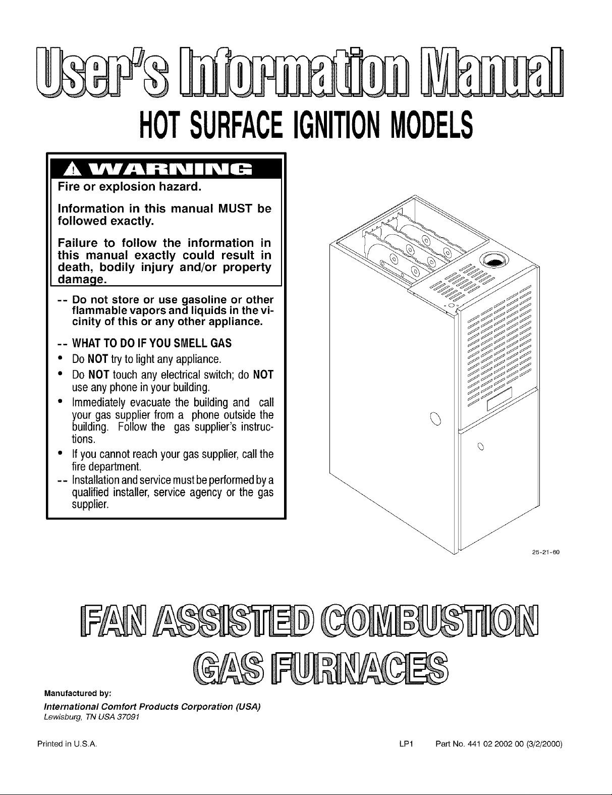
Fire or explosion hazard.
Information in this manual MUST be
followed exactly.
Failure to follow the information in
this manual exactly could result in
death, bodily injury and/or property
damage.
-- Do not store or use gasoline or other
flammable vapors and liquids in the vi-
cinity of this or any other appliance.
-- WHATTO DO IF YOU SMELL GAS
• DoNOT tryto lightany appliance.
• DoNOT touchany electrical switch; do NOT
use any phone inyour building.
• Immediately evacuate the building and call
your gas supplier from a phone outside the
building. Follow the gas supplier's instruc-
tions.
• Ifyou cannot reach your gas supplier,call the
firedepartment.
-- Installationandservicemustbe performedbya
qualified installer, service agency or the gas
supplier.
25-21-60
Manufactured by:
International Comfort Products Corporation (USA)
Lewisburg, TN USA 37091
Printed in U.S.A. LP1 Part No. 441 02 2002 O0 (3/2/2000)
Page 2
Fan Assisted Combustion Gas Furnace User'sInformationManual
Contents
Danger,Warningand Caution ................ 2
Safety Rules ............................. 3
CombustionAir (Yoursafety) ................ 3
Danger,Warningand Caution
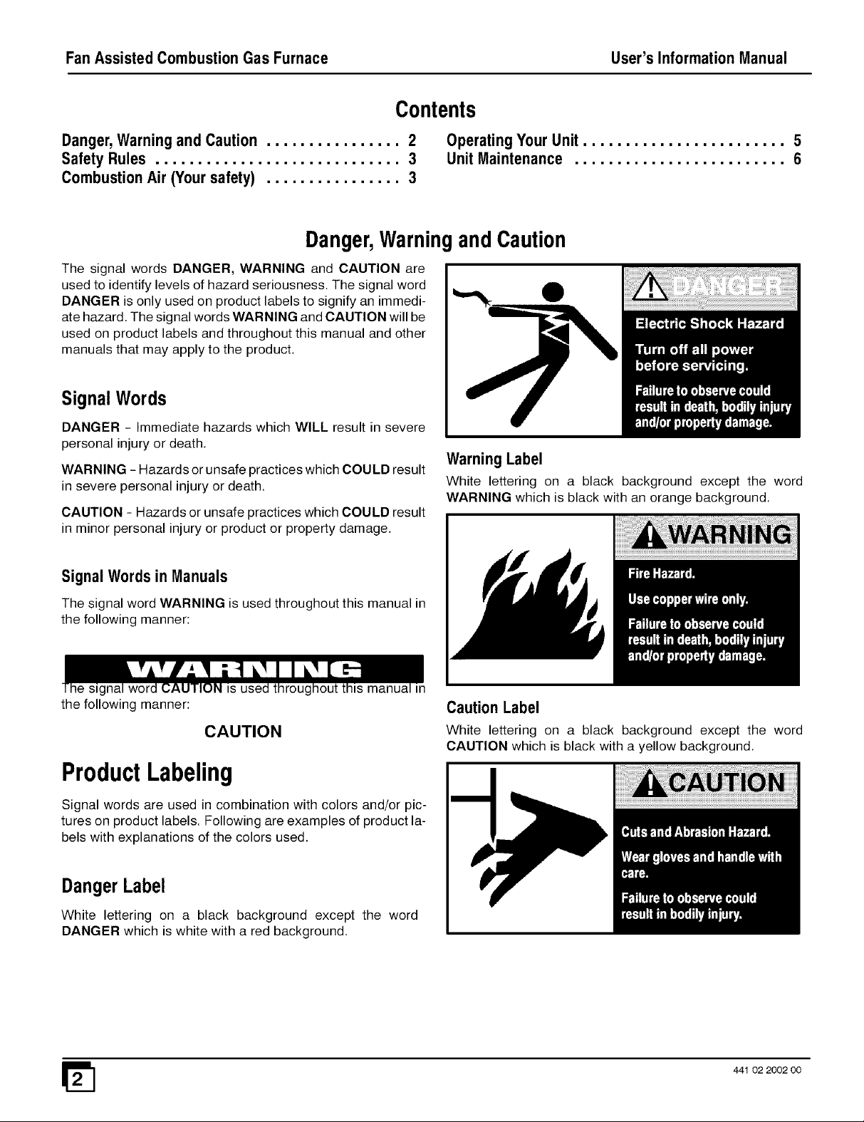
The signal words DANGER, WARNING and CAUTION are
used to identify levels of hazard seriousness. The signal word
DANGER is only used on product labels to signify an immedi-
ate hazard. The signal words WARNING and CAUTION will be
used on product labels and throughout this manual and other
manuals that may apply to the product.
SignalWords
DANGER - Immediate hazards which WILL result in severe
personal injury or death,
WARNING - Hazards or unsafe practices which COULD result
in severe personal injury or death.
CAUTION - Hazards or unsafe practices which COULD result
in minor personal injury or product or property damage.
OperatingYour Unit ........................ 5
Unit Maintenance ......................... 6
Warning Label
White lettering on a black background except the word
WARNING which is black with an orange background,
Signal Words inManuals
The signal word WARNING is used throughout this manual in
the following manner:
31S manua
the following manner:
CAUTION
ProductLabeling
Signal words are used in combination with colors and/or pic-
tures on product labels. Following are examples of product la-
bels with explanations of the colors used,
DangerLabel
White lettering on a black background except the word
DANGER which is white with a red background.
Caution Label
White lettering on a black background except the word
CAUTION which is black with a yellow background,
441 02 2002 00
Page 3
User's Information Manual FanAssisted CombustionGasFurnace
5. Check the combustion air supply. Some models use
air drawn from outside. Other models and other ap-
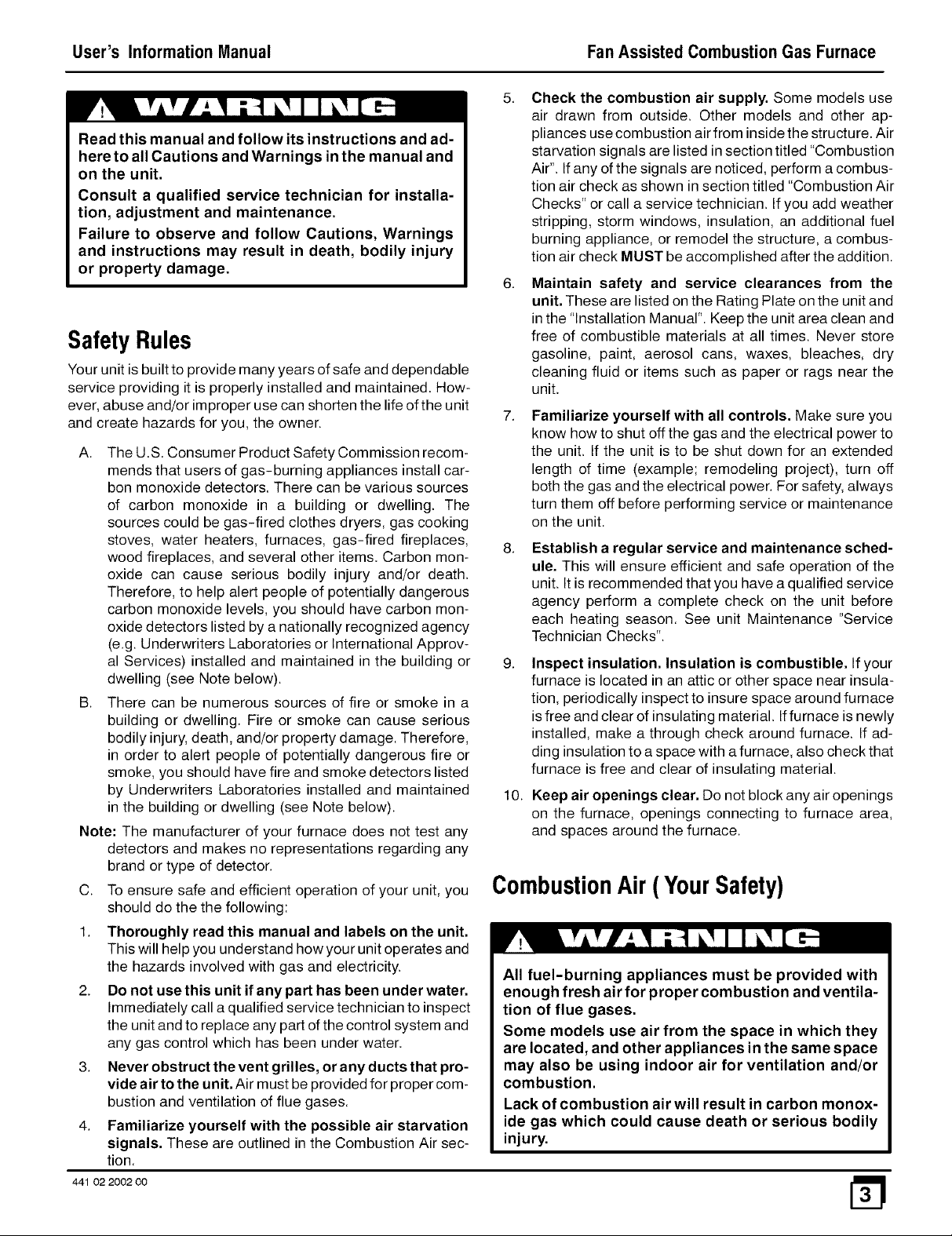
Read this manual and follow its instructions and ad-
here to all Cautions and Warnings in the manual and
on the unit.
Consult a qualified service technician for installa-
tion, adjustment and maintenance.
Failure to observe and follow Cautions, Warnings
and instructions may result in death, bodily injury
pliances use combustion air from inside the structure. Air
starvation signals are listed in section titled "Combustion
Air". If any of the signals are noticed, perform a combus-
tion air check as shown in section titled "Combustion Air
Checks" or call a service technician. If you add weather
stripping, storm windows, insulation, an additional fuel
burning appliance, or remodel the structure, a combus-
tion air check MUST be accomplished after the addition.
or property damage.
6. Maintain safety and service clearances from the
unit. These are listed on the Rating Plate on the unit and
in the "Installation Manual". Keep the unit area clean and
SafetyRules
Your unit is built to provide many years of safe and dependable
service providing it is properly installed and maintained. How-
ever, abuse and/or improper use can shorten the life of the unit
and create hazards for you, the owner.
A. The U.S. Consumer Product Safety Commission recom-
mends that users of gas-burning appliances install car-
bon monoxide detectors. There can be various sources
of carbon monoxide in a building or dwelling. The
sources could be gas-fired clothes dryers, gas cooking
stoves, water heaters, furnaces, gas-fired fireplaces,
wood fireplaces, and several other items. Carbon mon-
oxide can cause serious bodily injury and/or death.
Therefore, to help alert people of potentially dangerous
carbon monoxide levels, you should have carbon mon-
oxide detectors listed by a nationally recognized agency
(e.g. Underwriters Laboratories or International Approv-
al Services) installed and maintained in the building or
dwelling (see Note below).
B. There can be numerous sources of fire or smoke in a
building or dwelling. Fire or smoke can cause serious
bodily injury, death, and/or property damage. Therefore,
in order to alert people of potentially dangerous fire or
smoke, you should have fire and smoke detectors listed
by Underwriters Laboratories installed and maintained
in the building or dwelling (see Note below).
Note: The manufacturer of your furnace does not test any
detectors and makes no representations regarding any
brand or type of detector.
C. To ensure safe and efficient operation of your unit, you
should do the the following:
1. Thoroughly read this manual and labels on the unit.
This will help you understand how your unit operates and
the hazards involved with gas and electricity.
2. Do not use this unit if any part has been under water.
Immediately call a qualified service technician to inspect
the unit and to replace any part of the control system and
any gas control which has been under water.
3. Never obstruct the vent grilles, or any ducts that pro-
vide air to the unit. Air must be provided for proper com-
bustion and ventilation of flue gases.
4. Familiarize yourself with the possible air starvation
signals. These are outlined in the Combustion Air sec-
tion.
441 02 2002 00
free of combustible materials at all times. Never store
gasoline, paint, aerosol cans, waxes, bleaches, dry
cleaning fluid or items such as paper or rags near the
unit.
Familiarize yourself with all controls. Make sure you
know how to shut off the gas and the electrical power to
the unit. If the unit is to be shut down for an extended
length of time (example; remodeling project), turn off
both the gas and the electrical power. For safety, always
turn them off before performing service or maintenance
on the unit.
Establish a regular service and maintenance sched-
ule. This will ensure efficient and safe operation of the
unit. It is recommended that you have a qualified service
agency perform a complete check on the unit before
each heating season. See unit Maintenance "Service
Technician Checks".
9. Inspect insulation, Insulation is combustible, If your
furnace is located in an attic or other space near insula-
tion, periodically inspect to insure space around furnace
is free and clear of insulating material. Iffurnace is newly
installed, make a through check around furnace. If ad-
ding insulation to a space with a furnace, also check that
furnace is free and clear of insulating material.
10. Keep air openings clear. Do not block any air openings
on the furnace, openings connecting to furnace area,
and spaces around the furnace.
CombustionAir(YourSafety)
All fuel-burning appliances must be provided with
enough fresh air for proper combustion and ventila-
tion of flue gases.
Some models use air from the space in which they
are located, and other appliances in the same space
may also be using indoor air for ventilation and/or
combustion.
Lack of combustion air will result in carbon monox-
ide gas which could cause death or serious bodily
injury.
m
Page 4

Fan Assisted Combustion Gas Furnace User'sInformationManual
New materials and methods are being used in construction
and remodeling which result in lower energy costs for heating
and cooling. It may also mean your appliances may not be get-
ting enough air for combustion and ventilation of flue gases.
The use of exhaust fans, fireplaces, clothes dryers, and other
appliances consume air or vent it outside.
Ifthe appliances or heating unit can't get enough air, two condi-
tions may result:
1. The appliance or heating unit may produce carbon mon-
oxide gas.
Carbon monoxide or "CO" is a colorless and odorless
gas produced when fuel is not burned completely or
when the flame does not receive sufficient oxygen.
2. The appliance may not vent flue gases properly.
The following are signs that your appliances may not be getting
enough air for proper combustion.
Be aware of these signals;
1. Headaches-Nausea-Dizziness
2, Excessive humidity-Heavily frosted windows or a
moist "clammy" feeling in the structure.
3. Smoke from the fireplace won't draw up the chim-
ney.
Ifyou experience headaches, nausea, or dizziness,
carbon monoxide may be present.
Leave the house immediately and call your gas
supplier.
Carbon monoxide poisoning can result in death
from asphyxiation or serious bodily injury.
CombustionAir Checks
On appliances with a draft hood, check for spillage by
holding a lighted match 2 inches from the draft hood
opening. Reference Figure 1 which shows a water
heater draft hood.
A. Match flame pulls toward draft hood.
This indicates no spillage and that appliance is getting
enough air for combustion. Return exhausting devices
and appliances to the condition you found them.
B. Match goes out or flame wavers away from draft hood.
This indicates spillage and that appliance is not getting
enough air for combustion.
Figure 1 [ Water Heater Draft Hood
VentPipe_ DraftHood
wYaPtieCra/eGatsr_ / I ; __
Match
I\
If draft hood spillage is indicated:
1 . Check for plugged flue connectors and chimneys. Re-
pair stoppage and test again.
2. If you have a fireplace, open a window or door near the
fireplace and then check for spillage. If spillage stops, do
not use the fireplace until you can supply fresh air by a
permanent duct.
3. If you have kitchen and bathroom exhaust fans, turn
them OFF and check for spillage.
If spillage stops, do not use exhaust fans until you can
supply fresh air by a permanent duct. Circuit breakers for
fans should be turned off.
If any of the signals are noticed, perform a combustion air
check or call a service technician. If you add weather stripping,
storm windows, insulation, an additional fuel burning ap-
pliance, or remodel the structure, a combustion air check
MUST be accomplished after the addition.
Make the inspectionasfollows:
1. Close all doors and windows. If you have a fireplace,
start a fire and wait until flames are burning vigorously.
2. Turn on all exhausting devices, such as: kitchen and
bathroom exhaust fans and dryers (gas or electric).
3. Turn on all vented gas appliances, such as: heating
equipment (includes any room heaters) and water heat-
ers.
4. Wait ten (10) minutes for drafts to stabilize.
Draft hood spillage means there is not enough air
for proper combustion and carbon monoxide may
be present.
Keep a window open (a minimum of 2 inches) near
the appliance until a permanent air duct is installed.
Contact a qualified service agency.
Carbon monoxide poisoning can result in death
from asphyxiation or serious bodily injury.
Spillage means air starvation and a fresh air duct or air
intakes must be installed to provide air directly to the
area around the unit. These MUST comply with local and
state building codes or in their absence with the National
Fuel Gas Code NFPA 54 ANSI Z223.1, current edition or
in Canada the National Standard CAN/CGA 1-B149.
441 02 2002 O0
Page 5

User's Information Manual
FanAssisted CombustionGasFurnace
Figure 2 I Component Locations
I
Manual Gas
Gas Circulating Blower
Main Burners
Control
Board
Vent Pipe
Combustion
Blower
er
Pressure Switch
(2 switches on some models)
Circulating Blower
Motor
25-22-96
OperatingYourUnit
Keep the blower access door and all access panels in place ex-
cept for inspection or maintenance.
Before starting your unit be sure you read and understand all of
the procedures in this manual. Check to make sure the unit fil-
ter is clean and correctly installed.
Should overheating occur or the gas supply fail to shut
off, shut off the manual gas valve to the unit before shut-
ting off the electrical supply.
Carbon monoxide Poisoning Hazard.
Provisions for combustion and ventilation air must
be provided for in accordance with installations
instructions supplied with unit.
Failure to provide adequate combustion and ven-
tilation air can result in death and/or personal
injury.
StartingTheUnit
See Figure 3 for an illustration of the gas valve.
1. Turn the thermostat to its lowest temperature setting or
to OFF if equipped with a System Select Switch.
2. Turn OFF all electric power to the unit at the disconnect
switch or circuit breaker.
4. Remove the Iouvered access panel in front of the unit by
lifting the panel up and outwards. Removing the panel
will expose the gas control switch.
5. Slide the gas control switch to OFF. See Figure 3.
6. Wait five (5) minutes to clear out any gas. If you then
smell gas, STOP! Follow the safety information on the
cover of this manual. If you do not smell gas, go to the
next step.
7. Slide the control switch to ON.
8. Reinstall all access panels.
9. Turn ON all electrical power to the unit.
Typical Gas Valve
Figure 3 I
ManifoldJ
Pressuretap 25-22-93
10. Set the thermostat to the desired temperature and the
System Select Switch to HEAT.
The unit will activate an ignitor which lights the burner.
White Rodgers
GasControl
switch
ManifoldPressure
adjustmentunderscrew
7
OUTLET
441 02 2002 O0
Page 6

Fan Assisted Combustion Gas Furnace User'sInformationManual
System Retries
The ignition system tries to relight the burners whenever the
built-in flame sensor detects no flame.
TurningOff The unit
Set the thermostat to the lowest setting or set System Select
Switch to OFF if equipped.
Should overheating occur or the gas supply fail to shut
off, shut off the manual gas valve to the unit before shut-
ting off the electrical supply.
Extended Shutdown
1 . Set thermostat to lowest setting or set System Select
Switch to OFF if equipped.
2. Slide the gas valve control switch to OFF. See
( Figure 3)
3. Turn Manual Shutoff Valve to OFF position, ( at right
angle or 900 to gas line).
4. Turn electric power off. (May be left ON for set-back type
thermostat with batteries, provided thermostat has a
system select switch to place in the OFF position.)
L P ModelUnits
If your LP. (liquefied petroleum) gas unit is installed in a an ex-
cavated or low lying area, we recommend that you contact your
L.P. supplier about installing a warning device that would alert
you of a gas leak.
Have someone check the structure frequently during
cold weather to make sure it is warm enough to prevent
pipes from freezing. Suggest they call qualified service
agency, if required.
Unit Maintenance
Have your unit inspected and serviced on an annual basis (be-
fore the heating season) by a qualified service technician.
Electrical shock hazard.
Turn off electric power to unit before performing
any maintenance or removing panels or doors.
Failure to observe could result in death or bodily
injury.
Labeling
CAUTION
Label all wires prior to disconnection when servicing
controls. Wiring errors can cause improper and dan-
gerous operation.
Verify proper operation after servicing.
PressureSwitches
Fire or explosion hazard.
L.P.gas is heavier than air. Leaking gas can settle
in low areas such as a crawl space. If you suspect
the presence of gas, follow the instructions on the
cover of this manual.
Failure to observe could result in death, bodily in-
jury or property damage.
FreezingTemperaturesAnd YourStructure
Your unit is equipped with safety devices that may keep it from
operating if sensors detect abnormal conditions such as
clogged exhaust flues.
If your unit remains shut off during cold weather the water pipes
could freeze and burst, resulting in serious water damage.
If the structure will be unattended during cold weather you
should take these precautions.
1. Turn off main supply water into the structure and drain
the water lines if possible. Open faucets in appropriate
areas.
During regular yearly maintenance check for cracks in any
tubes on the pressure switches.
Air Filters
The air filter(s) should be inspected at least monthly and
cleaned or replaced as required. There are two types of filters
that are commonly used. The most widely used is the Fiber-
glass disposable type which should be REPLACED before it
becomes clogged. The other type is the washable type
constructed of aluminum mesh, foam, or reinforced fibers.
Washable filters may be cleaned by soaking in mild detergent
and rinsing with water.
Fire hazard from dust and lint buildup on internal
unit parts.
Never operate unit without a filter installed.
Failure to observe could result in death or bodily
injury.
Remember that dirty filters are the most common cause of in-
adequate heating or cooling performance.
441 02 2002 00
Page 7

User's Information Manual FanAssisted CombustionGasFurnace
Table 1
Unit Size
Heating Input
1000 x Btu h
40 - 50
40 - 50, 75, and 1O0
40 - 50, 75, and 1O0
75,100, and 125
1O0 and 125
125
150
Recommended Filter Sizes
Nominal Air Flow
Cubic Feet
per Minute (CFM)
800-900
900-1100
1100-1300
1300-1500
1500-1700
1900-2100
2300-2500
ReplacementFilters
Table 1 lists recommended sizes and types of filters that may
be used with your unit, based on the input rating and Btuh.
Replacement filters should be of the same type and size as the
originals, to ensure adequate air flow and filtering. A dispos-
able low velocity filter though, can be replaced with a washable
high velocity type. Do not replace a high velocity filter with a dis-
posable low velocity filter.
Filter Replacement - Upflow/Horizontal
The filter rack may be installed in the bottom of the blower
compartment, or on the outside on either side of the unit. A
plastic endcap is inserted in the filter rack after the filter is
installed. The endcap keeps air from escaping around the
open end of the filter rack. See Figure 4 for filter rack, filter and
endcap locations.
Filter racks attached to the unit are made so the filter simply
slides out one side for removal.
1. Remove the endcap from the filter rack.
2. Slide the filter out of the filter rack.
3. Inspect the filter(s) and replace or clean washable types.
Iffilter is aluminum mesh it should be recoated with filter
coating spray.
4. Reinstall the filter in the filter rack.
Some filters are marked with an arrow to indicate the
proper direction of air flow through the filter, The air
flow direction will be towards the blower motor.
Make sure filter is installed correctly.
5. Reinstall the endcap in the filter rack.
Recommended Filter Sizes
Sq, In. Surface Area/Nominal Size (inches)
Disposable Filters
500 or 20 x 25
600 or 20 x 30
350 or 14 x 25 (2Req.)
400 or 16 x 25 (2Req.)
500 or 20 x 25 (2 Req.)
600 or 20 x 30 (2 Req.)
600 or 20 x 30 (2 Req.)
Figure 4
I Filter Racks
/
Endcap
Filter
Filterinbottom
of Unit
Cleanable Filters
350 or 14 x 25
350 or 14 x 25
350 or 14 x 25
400 or 16 x 25
500 or 20 x 25
500 or 20 x 25
720 or 24 x 30
SideMounted
FilterRack
Return Air
Duct
441 02 2002 O0
Endcap
25-23-05
Page 8

Fan Assisted Combustion Gas Furnace User'sInformationManual
Lubrication
The circulating blower motor and combustion air blower do not
require lubrication.
Monthly Inspection
A properly adjusted gas unit should not require cleaning at fre-
quent intervals, but it should be inspected regularly to ensure
safe and efficient operation. A brief monthly inspection is rec-
ommended that does not require disassembly. In addition you
should have the unit inspected, and cleaned if required, by a
qualified service technician annually.
1. Check the vents to be sure they are clear and free of ob-
structions.
2. Check that the vent connector is in place, slopes upward
away from furnace, and is physically sound without
holes or excessive corrosion.
3. Check return air duct to make sure it is sealed to unit cas-
ing, terminates outside the space containing the fur-
nace, and that it is in good physical condition.
4. Inspect the unit base. All supports for furnace should be
structurally sound without sags, cracks, gaps, etc. be-
tween the furnace and the base.
5. Remove the front panel and use a flashlight to inspect
the visible part of the heat exchanger and main burners.
Check for loose soot and give particular attention to ob-
vious deterioration from corrosion or other sources. If
soot or deterioration is found inside the unit DO NOT OP-
ERATE UNIT; call a qualified service technician.
6. Inspect main burner flames for the following:
• Stable and blue flames. Dust may cause orange tips
or wisps of yellow, but flames must not have solid yel-
low tips.
• Flames extending directly from burner into heat ex-
changer.
• Flames do not touch sides of heat exchanger.
If abnormal flame appearance is identified do not
operate unit; call a qualified service technician.
ServiceTechnicianChecks
When the unit is being inspected for condition and operation
have the Service Technician check the following items.
1. Check that adequate combustion air is being supplied to
the unit by the air openings into or from the unit.
2. Check all flue gas passages including main burners,
heat exchanger, and vent.
3. Check gas pipe and all connections inside and leading to
the unit for leaks.
4. Check electrical wiring and connections.
5. Check supply and return air ducts for leakage, blockage
and connections to unit.
6. Check circulating air blower wheel and motor. Clean
them if required.
7. Perform an operational checkout on the unit to be sure
safety controls function and that unit operates properly.
For additional information the Service Technician can
consult the Installation Instructions and applicable Tech-
nical Support Manual for the unit.
441 02 2002 00
 Loading...