

INSTALLATION INSTRUCTIONS
R−410A Ducted Horizontal Heat Pump
Product Family: HC4H3
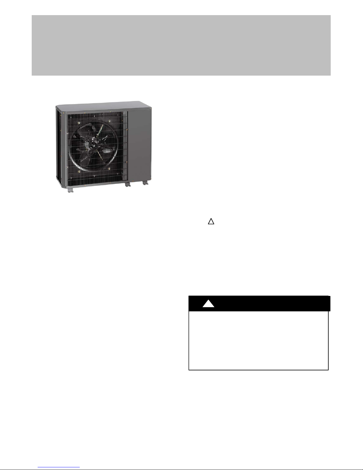
Figure 1 - HC4H3
NOTE: Read the entire instruction manual before starting
the installation.
TABLE OF CONTENTS
PAGE
SAFETY CONSIDERATIONS 1........................
INSTALLATION 2−6..................................
Step 1 − Complete Pre−Installation Checks 2........
Step 2 − Rig and Mount Unit 6.....................
Step 3 − Complete Refrigerant Piping Connections 6..
Step 4 − Make Electrical Connections 7.............
START−UP 10.......................................
SERVICE 10........................................
MAINTENANCE 15...................................
TROUBLESHOOTING 16−17..........................
SAFETY CONSIDERATIONS
Improper installation, adjustment, alteration, service,
maintenance, or use can cause explosion, fire, electrical
shock, or other conditions which may cause death, personal
injury, or property damage. Consult a qualified installer,
service agency, or your distributor or branch for information
or assistance. The qualified installer or agency must use
factory−authorized kits or accessories when modifying this
product. Refer to the individual instructions packaged with
the kits or accessories when installing.
Follow all safety codes. Wear safety glasses, protective
clothing, and work gloves. Use quenching cloth for brazing
operations. Have fire extinguisher available. Read these
instructions thoroughly and follow all warnings or cautions
included in literature and attached to the unit. Consult local
building codes and National Electrical Code (NEC) for
special requirements.
Recognize safety information. This is the safety−alert
symbol
instructions or manuals, be alert to the potential for personal
injury. Understand these signal words; DANGER,
WARNING, and CAUTION. These words are used with the
safety−alert symbol. DANGER identifies the most serious
hazards which will result in severe personal injury or death.
WARNING signifies hazards which could result in personal
injury or death. CAUTION is used to identify unsafe
practices which would result in minor personal injury or
product and property damage. NOTE is used to highlight
suggestions which will result in enhanced installation,
reliability, or operation.
!
!
When you see this symbol on the unit and in
!
ELECTRICAL SHOCK HAZARD
Failure to follow this warning could result in
personal injury or death.
Before installing, modifying, or servicing system,
main electrical disconnect switch must be in the
OFF position. There may be more than 1
disconnect switch. Lock out and tag switch with a
suitable warning label.
WARNING
428 01 9700 03 Sep 2010
INSTALLATION
!
UNIT OPERATION AND SAFETY HAZARD
Failure to follow this warning could result in personal
injury or equipment damage.
R−410A refrigerant systems operate at higher
pressures than standard R−22 systems. Do not use
R−22 service equipment or components on R−410A
refrigerant equipment.
PERSONAL INJURY AND EQUIPMENT DAMAGE
HAZARD
Failure to follow this caution may result in personal
injury and / or equipment damage.
DO NOT operate the unit without a filter or with grille
removed.
Step 1 —Complete Pre−Installation Checks
Unpack Unit
Move the unit to final location. Remove unit from carton,
being careful not to damage service valves and grilles.
Inspect Shipment
File a claim with the shipping company if shipment is
damaged or incomplete. Check the unit nameplates to
ensure units match job requirements.
WARNING
!
CAUTION
Consider System Requirements
Consult local building codes and NEC for special installation
requirements.
Allow sufficient space for airflow clearance, wiring,
refrigerant piping, and servicing unit. See Figure 3.
Locate unit so that condenser airflow is unrestricted on both
sides. Refer to Figure 3.
Unit may be mounted on a level pad directly on base legs or
mounted on raised pads at support points. See Figure 3 for
center of gravity.
Matching the Heat Pump to an Indoor Unit
The HC4H3 ducted heat pump units can be matched to
corresponding indoor units. The HC4H3 unit can be
matched with underceiling and residential fan coils and
evaporator coils. Refer to separate indoor unit literature for
more information.
Expansion Device − Cooling Mode
A hard shutoff, thermostatic expansion valve (TXV) is
required at the indoor section of the system for proper
operation of these products. If the indoor section of the
system is not equipped with a hard shutoff TXV, refer to
Spec Sheet for the correct TXV kit to be installed. Follow
the instructions in the kit for proper installation.
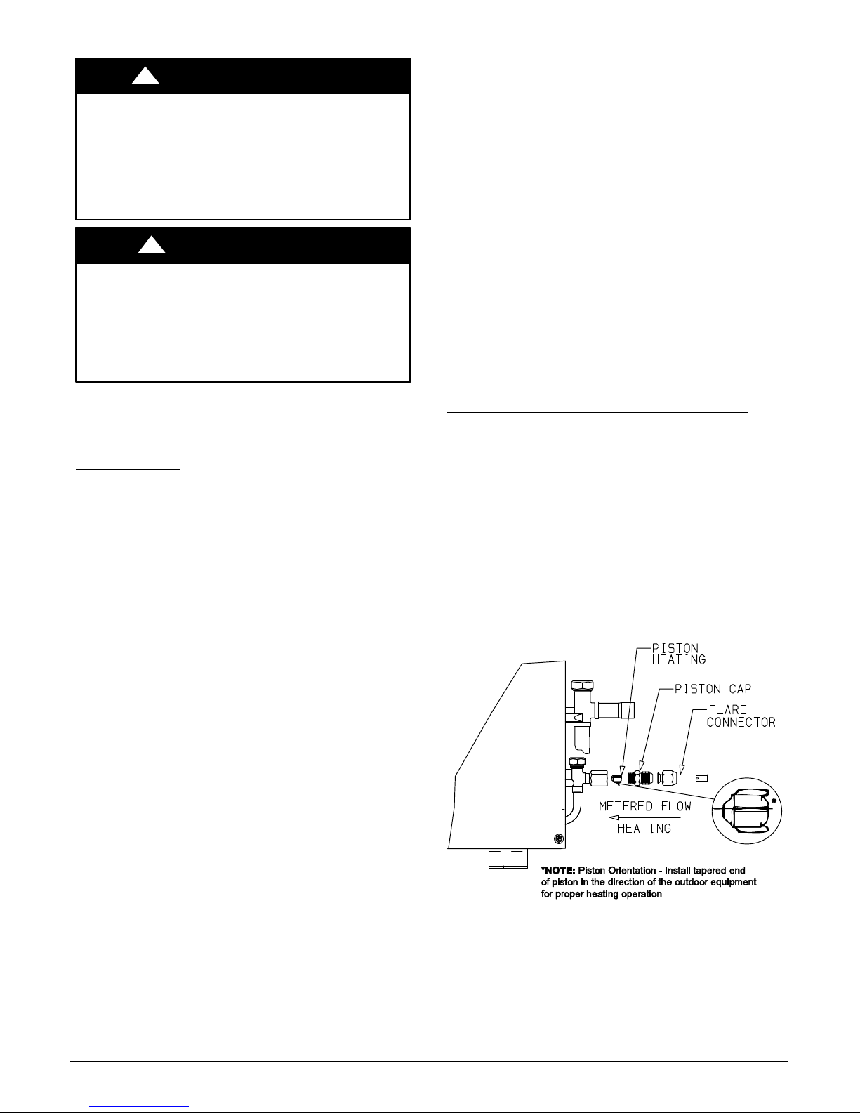
Check AccuRater Metering Device − Heating Mode
The correct AccuRater (bypass type) refrigerant control is
required for system capacity optimization. An AccuRater
device with field−replaceable piston is supplied with the
outdoor unit (see Figure 2).
Do not interchange components between the AccuRater
device types. Matching of outdoor unit with indoor unit may
require field replacement of piston. Replace piston, if
required, before connecting refrigerant lines. See Figure 2.
Piston replacement instructions are included in the indoor
unit installation instructions. After system installation is
complete, see the Refrigerant Charging section in this
document to check and/or adjust refrigerant charge.
2 428 01 9700 03
A07407b
Figure 2 - AccuRater (bypass type)
Metering Device Components
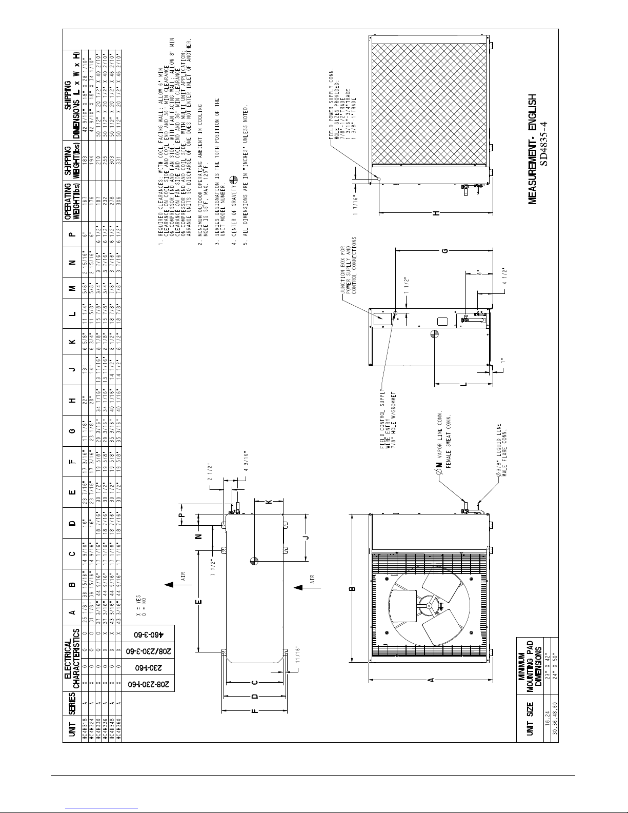
1. REQUIRED CLEARANCES: WITH COIL FACING WALL; ALLOW 6 MIN
CLEARANCE ON COIL SIDE AND COIL END AND 36 MIN CLEARANCE
ON COMPRESSOR END AND FAN SIDE. WITH FAN FACING WALL; ALLOW 8 MIN
CLEARANCE ON FAN SIDE AND COIL END AND 36 MIN CLEARANCE
ON COMPRESSOR END AND COIL SIDE. WITH MULTI UNIT APPLICATION;
ARRANGE UNITS SO DISCHARGE OF ONE DOES NOT ENTER INLET OF ANOTHER.
3. SERIES DESIGNATION IS THE 10TH POSITION OF THE
2. MINIMUM OUTDOOR OPERATING AMBIENT IN COOLING
UNIT MODEL NUMBER.
MODE IS 55 $
5. ALL DIMENSIONS ARE IN INCHES UNLESS NOTED.
FIELD POWER SUPPLY CONN.
HOLE SIZES PROVIDED:
7/8−1/2TRADE
1 3/16−3/4TRADE
1 3/8−1TRADE
F, MAX. 125 $F.
OPERATING
WEIGHT(lbs)
4. CENTER OF GRAVITY
14 1/2 8 1/2 18 7/8 7/8 3 7/16 6 1/2 278 303 50 1/2 X 20 1/2 X 46 2/10
14 1/2 8 1/2 18 7/8 7/8 3 7/16 6 1/2 306 331 50 1/2 X 20 1/2 X 46 2/10
11/16 8 1/8 15 7/8 3/4 3 7/16 6 1/2 187 210 50 1/2 X 20 1/2 X 40 2/10
3 11/16 8 1/8 15 7/8 3/4 3 7/16 6 1/2 232 255 50 1/2 X 20 1/2 X 40 2/10
6 5/8 11 1/4 5/8 2 15/16 6 167 183 42 9/10 X 18 X 28 1/10
14 6 3/4 11 5/8 5/8 2 15/16 6 176 194 42 9/10 X 18 X 34 1/10
4 3/16
2 1/2
1 7/16
JUNCTION BOX FOR
POWER SUPLLY AND
CONTROL CONNECTIONS
FIELD CONTROL SUPPLY
WIRE ENTRY
7/8 HOLE W/GROMMET
1 1/2
8
L
VAPOR LINE CONN.
M
FEMALE SWEAT CONN.
MEASUREMENT− ENGLISH
4 1/2
1
K
P
X = YES
O = NO
N
7 1/2
AIR
E
J
AIR
B
460−3−60
208/230−3−60
230−1−60
208−230−1−60
11/16
A
DIMENSIONS
FDC
UNIT SERIES ABC DE FG H J K L MNP
HC4H318 A XOOO25
HC4H324 A XOOO31
HC4H330 A XOOO37
HC4H336 A XOXX37
HC4H348 A XOXX43
HC4H360 A XOXX43
UNIT SIZE
Figure 3 - HC4A3 Unit Dimensions
428 01 9700 03 3
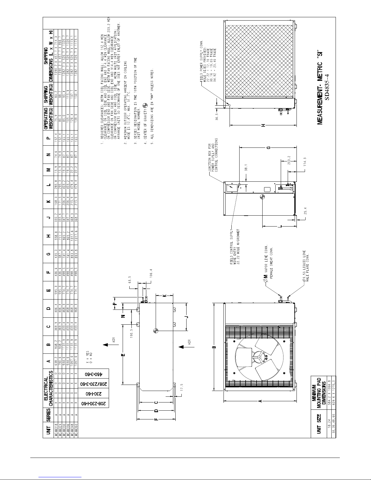
FIELD POWER SUPPLY CONN.
R
HOLE SIZES PROVIDED:
22.22 − 12.70 TRADE
30.16 − 19.05 TRADE
34.92 − 25.40 TRADE
1. REQUIRED CLEARANCES: WITH COIL FACING WALL; ALLOW 152.4 MIN
CLEARANCE ON COIL SIDE AND COIL END AND 914.4 MIN CLEARANCE
ON COMPRESSOR END AND FAN SIDE. WITH FAN FACING WALL; ALLOW 203.2 MIN
CLEARANCE ON FAN SIDE AND COIL END AND 914.4 MIN CLEARANCE
ON COMPRESSOR END AND COIL SIDE. WITH MULTI UNIT APPLICATION;
ARRANGE UNITS SO DISCHARGE OF ONE DOES NOT ENTER INLET OF ANOTHER.
85.0 95.4 1282.7 X 520.7 X 1020.7
105.4 115.9 1282.7 X 520.7 X 1020.7
126.4 137.7 1282.7 X 520.7 X 1173.1
WEIGHT(KG)
OPERATING
165.1
165.1
87.3 165.1
215.9 479.4 22.2 87.3
330.2 168.3 285.8 15.9 74.6 152.4 75.9 83.2 1090.2 X 457.7 X 714.3
355.6 171.5 295.3 15.9 74.6 152.4 80.0 88.2 1090.2 X 457.7 X 866.7
347.7 206.4 403.2 19.0
347.7 206.4 403.2 19.0 87.3
711.2
558.8
741.4 865.2
741.4 865.2
893.8 1017.6 368.3
3. SERIES DESIGNATION IS THE 10TH POSITION OF THE
2. MINIMUM OUTDOOR OPERATING AMBIENT IN COOLING
UNIT MODEL NUMBER.
MODE IS 12.8 $
C, MAX. 51.7 $C.
139.0 150.4 1282.7 X 520.7 X 1173.1
165.1
215.9 479.4 22.2 87.3
893.8 1017.6 368.3
4. CENTER OF GRAVITY
5. ALL DIMENSIONS ARE IN MM UNLESS NOTED.
36.5
JUNCTION BOX FOR
POWER SUPLLY AND
CONTROL CONNECTIONS
FIELD CONTROL SUPPLY
WIRE ENTRY
22.22 HOLE W/GROMMET
38.1
MEASUREMENT− MET
203.2
114.3
25.4
L
UNIT SERIES ABC DE FG H J K L MNP
XOOO 638.2 938.2 369.9 406.4 595.3 436.6 435.0
XOOO 790.6 938.2 369.9 406.4 595.3 436.6 587.4
HC4H318 A
HC4H324 A
XOOO 944.6 1131.9 433.4 468.3 774.7 498.5
HC4H330 A
XOXX 944.6 1131.9 433.4 468.3 774.7 498.5
HC4H336 A
XOXX 1097.0 1131.9 433.4 468.3 774.7 498.5
HC4H348 A
XOXX 1097.0 1131.9 433.4 468.3 774.7 498.5
HC4H360 A
X = YES
O = NO
VAPOR LINE CONN.M
63.5
106.4
FEMALE SWEAT CONN.
K
N
AIR
N
190.5
J
AIR
B
460−3−60
208/230−3−60
230−1−60
208−230−1−60
17.5
A
DIMENSIONS
FDC
UNIT SIZE
4 428 01 9700 03
Figure 4 - HC4A3 Unit Dimensions

Table 1—HC4H318−60 Physical Data
UNIT HC4H3 18 24 30 36 48 60
NOMINAL CAPACITY Tons 1.5 2.0 2.5 3.0 4.0 5.0
OPERATING WEIGHT lb (kg) 167 (75.75) 176 (79.83) 187 (84.82) 232 (105.23) 278 (126.10) 306 (138.80)
REFRIGERANT TYPE R-410A
METERING DEVICE TXV (Indoor Unit)
CHARGE* (lb) (kg) 6.8 (3.89) 7.0 (3.18) 12.0 (5.45) 12.5 (5.68) 12.2 (5.55) 12.8 (5.82)
COMPRESSOR
Type Scroll
Oil Charge (POE -oz) 25.0 25.0 25.0 25.0 42.0 42.0
Crankcase Heater (watts) — — 40 40 40 40
OUTDOOR FAN
Rpm/Cfm 840/1720 840/1720 850/3900 850/3900 850/3900 850/3900
Diameter in. (mm) 18 (457) 18 (457) 24 (610) 24 (610) 24 (610) 24 (610)
No. Blades 3 3 3 3 3 3
Motor (hp)
OUTDOOR COIL
Face Area sq. ft. (sq. m.) 5.8 (.54) 7.3 (.68) 12.1 (1.12) 12.1 (1.12) 14.1 (1.31) 14.1 (1.31)
No. Rows 3 3 2 3 3 3
FPI 20 20 20 20 20 20
HIGH PRESSURE SWITCH
Cut-In (psig) Cutout (psig)
LOW PRESSURE SWITCH
Low Cutout (psig)
Low Cut-in (psig)
REFRIGERANT LINES
Connection Type Sweat
Liquid Line (in.) OD
Vapor Line (in.) OD
Max Length ft (m) 200 (60.96)
Max Lift ft (m) 65 (19.81)
Max Drop ft (m) 150 (45.72)
CONTROLS
Fusible Plug F (C) 210 (98.89)
Control Voltage 24 vac
System Voltage 208/230 v 208/230 v 208/230 v 208/230 v, Single and 3 Phase, 460 v, 3 Phase
FINISH Gray
* Unit shipped with full factory charge. See ARI (Air Conditioning and Refrigeration Institute) capacity table for proper charge and piston for each fan coil type.
Valve connection size is 7/8 inch. Recommended line size is 1-1/8 inches.
24 v and a minimum of 40 va is provided in the fan coil unit.
FPI - Fins Per Inch
POE - Polyol Ester
1/8 1/8 1/4 1/4 1/4 1/4
420 ± 25
650 ± 10
20 ± 5
45 ± 25
420 ± 25
650 ± 10
20 ± 5
45 ± 25
5/8 3/4 7/8 7/8†
420 ± 25
650 ± 10
20 ± 5
45 ± 25
3/8
420 ± 25
650 ± 10
20 ± 5
45 ± 25
420 ± 25
650 ± 10
20 ± 5
45 ± 25
420 ± 25
650 ± 10
20 ± 5
45 ± 25
428 01 9700 03 5
Step 2 —RIG AND MOUNT UNIT
Mounting on Ground
Mount unit on a solid, level concrete pad. Position unit so
water or ice from roof does not fall directly onto unit. Use
field−provided snow stand or ice rack where prolonged
subfreezing temperatures or heavy snow occurs.
If conditions or local codes require unit be fastened to a pad,
6 field−supplied tiedown bolts should be used and fastened
through slots provided in unit mounting feet.
Mounting on Roof
Mount unit on a level platform or frame at least 6 in. (152.4
mm) above roof surface. Isolate unit and tubing from
structure.
Rigging
!
PERSONAL INJURY AND/OR EQUIPMENT
DAMAGE HAZARD
Failure to follow this caution may result in personal
injury and/or equipment damage.
Be sure unit panels are securely in place prior to
rigging.
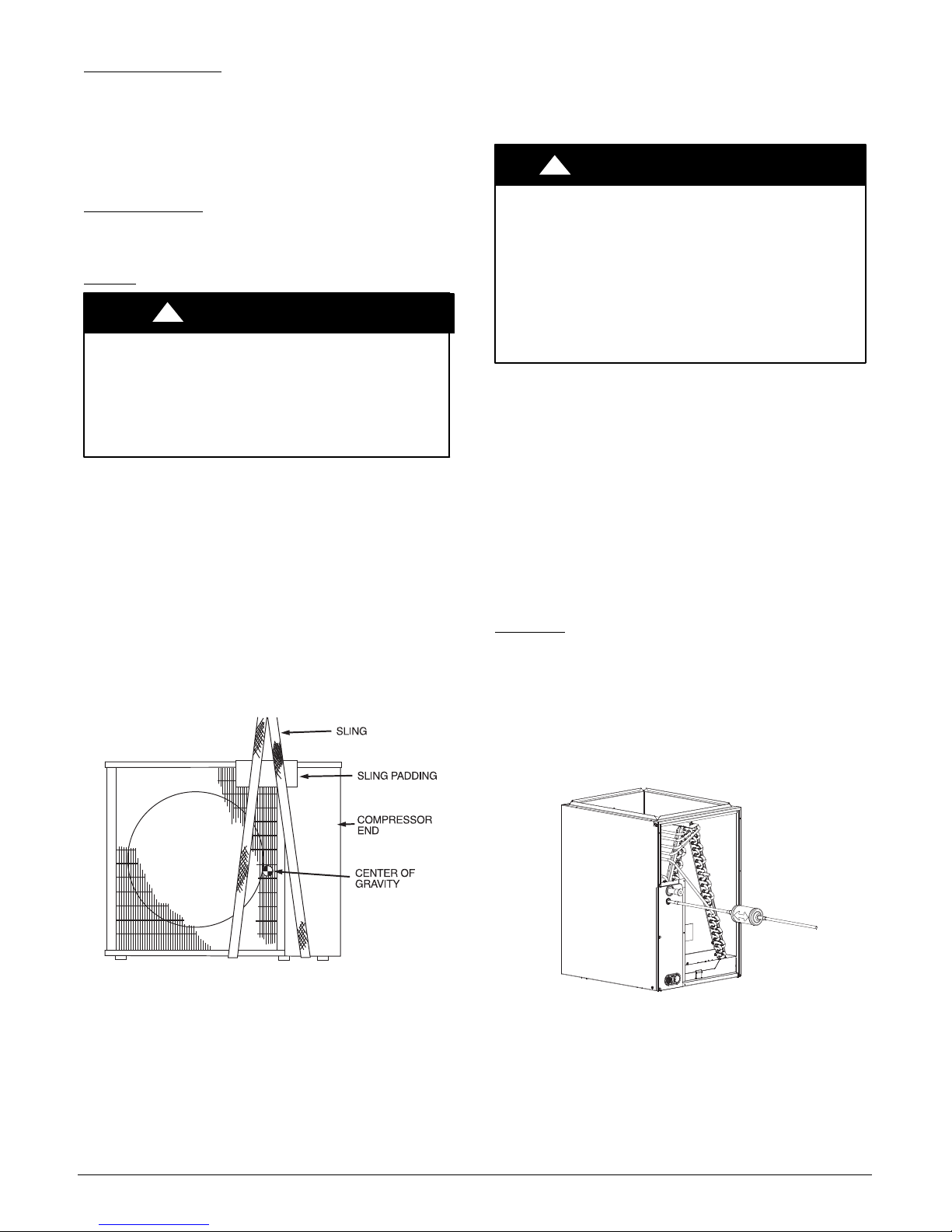
Keep the unit upright and lift unit using a sling. Use
cardboard or padding under the sling, and spreader bars to
prevent sling damage to the unit. See Figure 5. See
Figure 3 for center of gravity reference. Install the unit so
that the coil does not face into prevailing winds. If this is not
possible and constant winds above 25 mph are expected,
use accessory wind baffle. See installation instructions
provided with the accessory kit.
NOTE: Accessory wind baffles should be used on all units
with accessory low ambient temperature control.
Field−fabricated snow or ice stands may be used to raise
unit when operation will be required during winter months.
Units may also be wall mounted using the accessory wall
mounting kit.
CAUTION
Step 3 —COMPLETE REFRIGERANT PIPING
CONNECTIONS
Outdoor units may be connected to indoor units using
field−supplied tubing of refrigerant grade and condition. See
Table 1 for correct line sizes. Do not use less than 10 ft
(3.05 m) of interconnecting tubing.
!
UNIT DAMAGE HAZARD
Failure to follow this caution may result in equipment
damage or improper operation.
If any section of pipe is buried, there must be a 6 in.
(152.4 mm) vertical rise to the valve connections on
the outdoor unit. If more than the recommended
length is buried, refrigerant may migrate to cooler,
buried section during extended periods of system
shutdown. This causes refrigerant slugging and
could possibly damage the compressor at start−up.
When more than 80 ft (24.38 m) of interconnecting tubing
and more than 20 ft (6.10 m) of vertical lift is used, consult
the residential Long Line Application Guide for required
accessories. If either refrigerant tubing or indoor coil is
exposed to the atmosphere, the system must be evacuated
following good refrigeration practices.
Run refrigerant tubes as directly as possible, avoiding
unnecessary turns and bends. Suspend refrigerant tubes so
they do not damage insulation on vapor tube and do not
transmit vibration to structure. Also, when passing
refrigerant tubes through a wall, seal the opening so that
vibration is not transmitted to structure. Leave some slack in
refrigerant tubes between structure and outdoor unit to
absorb vibration. Refer to separate indoor unit installation
instructions for additional information.
Filter Drier
Refer to Figure 6 and install filter drier as follows:
1. Braze 5 in. (127 mm) liquid tube to the indoor coil.
2. Wrap filter drier with damp cloth.
3. Braze filter drier to 5 in. (127 mm) long liquid tube
from step 1.
4. Connect and braze liquid refrigerant tube to the filter
drier.
CAUTION
Figure 5 - Lifting Unit with Sling
6 428 01 9700 03
A07396
A05227
Figure 6 - Filter Drier Components
The filter drier must be replaced whenever the refrigeration
system is exposed to the atmosphere.
Only use factory specified liquid−line filter driers with rated
working pressures less than 600 psig.
NOTE: Do not install a suction−line filter drier in liquid line.
 Loading...