

ICP C9MPX100L20A2, H9MPX060F12A2, H9MVX080J20A1, H9MVX100L20A1, T9MPX080J16A2 Installation Guide
...
INSTALLATION INSTRUCTIONS
For the replacement of Secondary Heat Exchanger
Part Numbers 1174980, 1174981, 1174982 & 1177461
This kit is designed to replace the secondary heat exchanger on the
95% N9MPX, *gUHX, *gMPX & *gMVX Furnaces
* Denotes Brand (T, H or C)
SAFETY CONSIDERATIONS
Improper installation, adjustment, alteration, service,
maintenance, or use can cause explosion, fire, electrical
shock, or other conditions which may cause death,
personal injury, or property damage. Consult a qualified
installer, service agency, or your distributor or branch for
information or assistance. The qualified installer or
agency must use factory-authorized kits or accessories
when modifying this product. Refer to the individual
instructions packaged with the kits or accessories when
installing.
Follow all safety codes. Wear safety glasses, protective
clothing, and work gloves. Use quenching cloth for
brazing operations. Have fire extinguisher available. Read
these instructions thoroughly and follow all warnings or
cautions included in literature and attached to the unit.
Consult local building codes, the current editions of the
National Fuel Gas Code (NFCG) NFPA 54/ANSI Z223.1,
National Electrical Code (NEC) NFPA 70.
In Canada refer to the current editions of the National
standards of Canada CAN/CSA-B149.1 and .2 Natural
Gas and Propane Installation Codes, and Canadian
Electrical Code CSA C22.1.
Recognize safety information. This is the safety-alert
symbol _. When you see this symbol on the unit and in
instructions or manuals, be alert to the potential for
personal injury. Understand these signal words;
DANGER, WARNING, and CAUTION. These words are
used with the safety-alert symbol. DANGER identifies the
most serious hazards which will result in severe personal
injury or death. WARNING signifies hazards which could
result in personal injury or death. CAUTION is used to
identify unsafe practices which may result in minor
personal injury or product and property damage. NOTE is
used to highlight suggestions which will result in
enhanced installation, reliability, or operation.
DESCRIPTION AND USAGE
Use this secondary heat exchanger kit to replace a failed
secondary heat exchanger. This secondary heat exchanger
kit contains the following items:
Parts Supplied with Each Kit Qty.
Secondary Heat Exchanger/Panel Assembly 1
(includes insulation)
Panel Assembly Screws 20 Max
Turbulators, Short 14 Max
Turbulators, Long 14 Max
Collector Box Gasket 1
Transition Assembly Gasket 1
Inducer Assembly Gasket 1
Installation Instructions 1
FIRE EXPLOSION AND ELECTRICAL HAZARD
Failure to follow this warning could result in property damage,
personal injury, and/or death.
Turn off gas and electric supplies to unit before beginning any
installation or modification.
Turn off electric power supply at disconnect switch or service
panel beofre starting installation. Tag and lockout shutoff(s) with
appropriate device warning labels. There may be more than one
disconnect.
Follow the operating instructions on label attached to furnace.
UNIT OPERATION HAZARD
Failure to follow this caution may result in unit damage or
improper operation.
Label all wires prior to disconnection when servicing
controls. Wiring errors can cause improper and dangerous
operation.
Kit Part
1177461
1174980
1174981
1174982
* Denotes Brand (T, H or C)
*9UHX060F *9MPX060F
*9UHX080J *9MPX080J
*9U HX100L *9M PX100L
Used with Models
*9MVX040F
*9MVX060F
*9MVX080J
*9MVX100L
INTRODUCTION
This instruction covers installation of the secondary heat
exchanger kit part number 1174980, 1174981, 1174982 &
1177461 for all 95% furnaces.
Specifications subject to change without notice.
D'EQUIPMENT D'OPERATION
Lors des operations d'entretien des commandes, etiqueter
tousles ills avant de les deconnecter. Toute erreur de
c&blage peut 6tre une source de danger et de panne.
CUT HAZARD
Failure to follow this caution may result in personal injury.
Sheet metal parts may have sharp edges or burrs, use care and
wear appropriate protective clothing and gloves when handling
parts.
441 06 1077 02 June 2009
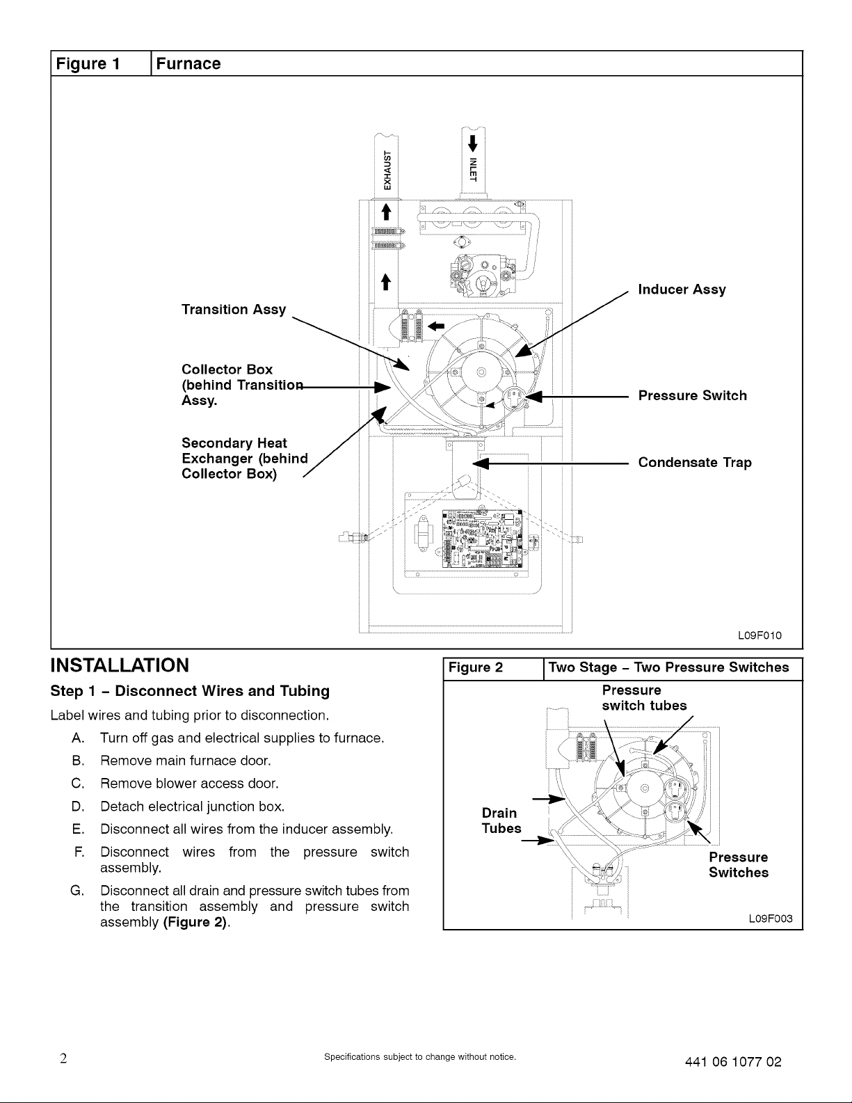
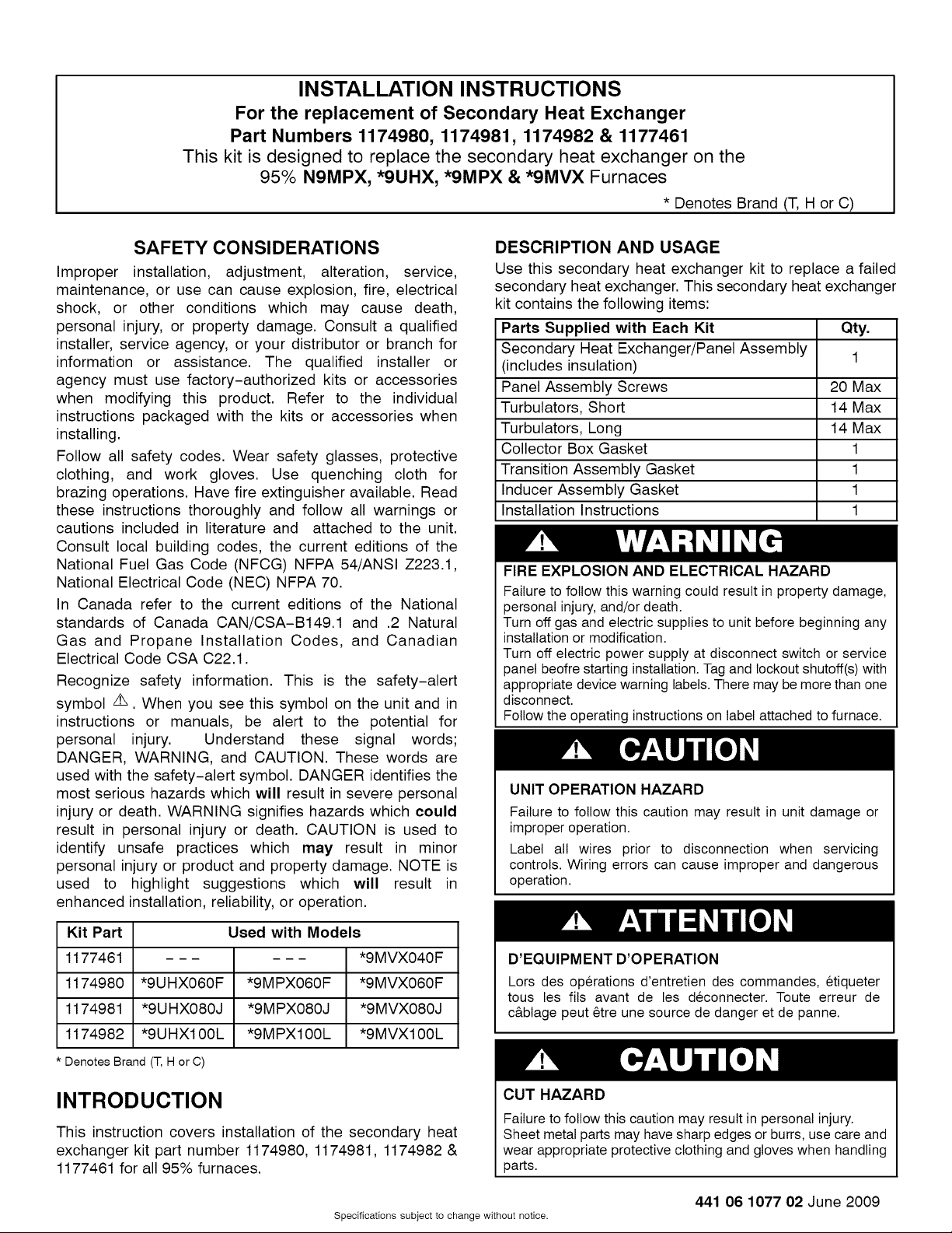
Figure 1 IFurnace
Transition Assy
Collector Box
(behind Transition
Assy.
Secondary Heat
Exchanger (behind
Collector Box)
-r
,x,
Inducer Assy
Pressure Switch
............................
Condensate Trap
INSTALLATION
Step 1 - Disconnect Wires and Tubing
Label wires and tubing prior to disconnection.
A. Turn off gas and electrical supplies to furnace.
B. Remove main furnace door.
C. Remove blower access door.
D. Detach electrical junction box.
E. Disconnect all wires from the inducer assembly.
F. Disconnect wires from the pressure switch
assembly.
G. Disconnect all drain and pressure switch tubes from
the transition assembly and pressure switch
assembly (Figure 2).
...... ........................................................ _ ....,
Figure 2
Drain
Tubes
L09 F010
ITwo Stage - Two Pressure Switches
Pressure
switch tubes
Pressure
Switches
i
L09F003
2 Specifications subject to change without notice. 441 06 1077 02
 Loading...