

ICP C9MPT050F12B1, C9MPT075F14B1, C9MPT100J16B1, C9MPT125L20B1, C9MPV050F12B1 Installation Guide
...
90+2-stage& *9MPT & *9MPV
VariableSpeed
Category ry
!veoFU!onroaCeo,. CT
S ct IV definition.
FAN ASSISTED,
SAFETY REQUIREMENTS
This furnace ca nbe installed as adirect vent furnace using outside air for combustion or the furnace can use air from inside the structure for combustion.
The INLET air pipe is optional. If combustion air comes from inside the structure, adequate make up air MUST be provided to compensate for oxygen
burned. See the Indoor Combustion Airsection inthe Combustion and Ventilation Aircha pter. If combustion air is drawn from outside the structure, it
MUST be taken from the same atmospheric pressure zone as the vent pipe.
Recognize safety information. This is the safety- alert symbolS. I .When you see this symbol on the furnace and in instructions manuals be alert to the
potential for personal injury.
Understand the signal words DANGER, WARNING, or CAUTION. These words are used with the safety-alert symbol. DANGER identifies the most
serious hazards, those that will result in severe personal injury or death. WARNING signifies a hazard that could result in personal injury or death.
CAUTION is used to identify unsafe practices that may result in minor personal injury or product and property damage. NOTE is used to highlight
suggestions that will result in enhanced installation, reliability, or operation.
Installing and servicing heating equipment can be hazardous due to gas and electrical components. Only trained and qualified personnel should install,
repair, or service heating equipment.
Untrained service personnel can perform basic maintenance functions such as cleaning and replacing air filters. All other operations must be performed
by trained service personnel. When working on heating equipment, observe precautions in the literature, on tags, and on labels attached to or shipped
with the unit and other safety precautions that may apply.
Follow all safety codes. In the United States, follow all safety codes including the current edition National Fuel Gas Code (NFGC) ANSI
Z223.1 - 2002/N FPA No. 54-2002. InCanada, refer tothecurrent edition of the National Standard of Canada Natural Gas and Propane Installation Code
(NSCNGPIC) CSA B149.1-00. Wear safetyglassesandworkgloves. Havefireextinguisher availableduringstart-upand adjustment procedures and
service calls.
These instructions cover minimum requirements and conform to existing national standards and safety codes. In some instances, these instructions
exceed certain local codes and ordinances, especially those that may not have kept up with changing residential construction practices. We require
these instructions as a minimum for a safe installation.
,j'_' %%
! i¸¸
International Comfort Products, LLC
Lewisburg, TN 37091
Table of Contents
1.SafeInstallation Requirements ................... 3
2.Installation ................................... 4
3.Combustion&VentilationAir ..................... 8
4.Vent& CombustionAir Piping ................... 12
5.GasSupply and Piping ........................ 30
6.ElectricalWiring .............................. 33
ELECTRIC SHOCK HAZARD
Failure to follow safety
warnings exactly could result
in serious injury, death, and/or
property damage.
Turn Off All Power Before
Servicing.
Printed in U.S.A. 2/9/2005 440 01 2020 (07)
7. DuctworkandFilter ....................... 35
8. Checks and Adjustments .................... 38
9. FurnaceMaintenance ...................... 40
10.SequenceofOperation & Diagnostics .......... 41
11.Concentric VentTermination................. 46
TechSupportand Parts ....................... 49
CARBON MONOXIDE POISONING AND FIRE
HAZARD.
Failure to follow safety warnings exactly cou Id
result in serious injury, death, and/or property
damage.
This furnace is not designed for use in mobile
homes, trailers or recreational vehicles.
INSTALLER: Affix these instructions
on or adjacent to the furnace.
CONSUMER: Retain these
instructions for future reference.
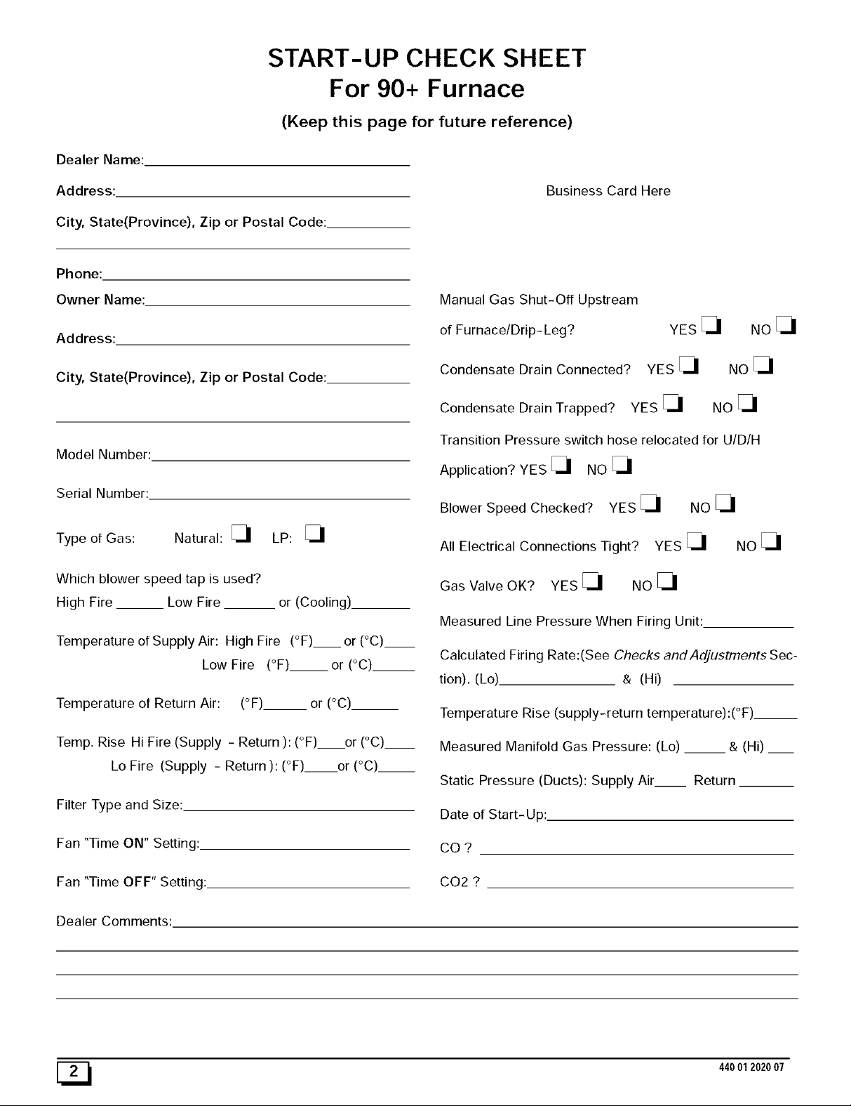
Dealer Name:
START-UP CHECK SHEET
For 90+ Furnace
(Keep this page for future reference)
Address:
City, State(Province), Zip or Postal Code:
Phone:
Owner Name:
Address:
City, State(Province), Zip or Postal Code:
Model Number:
Serial Number:
Type of Gas: Natural: _ LP:
Which blower speed tap is used?
High Fire __ Low Fire or (Cooling).
Temperature of Supply Air: High Fire (°F)__ or (°C)__
Low Fire (°F).__or (°C)__
Business Card Here
Manual Gas Shut-Off Upstream
of Furnace/Drip- Leg?
Condensate Drain Connected?
Condensate Drain Trapped? YES
Transition Pressure switch hose relocated for U/D/H
Application? YES _ NO
Blower Speed Checked? YES _ NO
All Electrical Connections Tight? YES _ NO
Gas Valve OK? YES _ NO
Measured Line Pressure When Firing Unit:
Calculated Firing Rate:(See Checks and Adjustments Sec-
tion). (Lo) & (Hi)
YES
YES
NOE_
NO
NO
Temperature of Return Air: (°F)__ or (°C)__
Temp. Rise Hi Fire (Supply - Return ): (°F) or (°C)__
Lo Fire (Supply - Return ): (°F) or (°C)__
Filter Type and Size:
Fan "Time ON" Setting:.
Fan "Time OFF" Setting:
Dealer Comments:
[_ 44001202007
Temperature Rise (supply-return temperature):(°F)__
Measured Manifold Gas Pressure: (Lo) __ & (Hi) __
Static Pressure (Ducts): Supply Air Return
Date of Start-Up:
CO?
CO2 ?
1. Safe Installation Requirements
FIRE, EXPLOSION, AND ASPHIXlATION HAZARD
Improper adjustment, alteration, service,
maintanence or installation could cause serious
injury, death and/or property damage.
Installation or repairs made by unqualified persons
could result in hazards to you and others.
Installation MUST conform with local codes or, in
the absence of local codes, with codes of all
governmental authorities having.jurisdiction.
The information contained in this manual is
intended for use by a qualified service agency that
is experienced in such work, is familiar with all
precautions and safety procedures required in
such work, and is equipped with the proper tools
and test instruments.
NOTE: This furnace is design-certified by the CSA International
(formerly AGA and CGA) for installation in the United States and
Canada. Refer to the appropriate codes, along with this manual,
for proper installation.
Use only the Type of gas approved for this furnace (see
Rating Plate on unit). Overfiring will result in failure of heat
exchanger and cause dangerous operation. (Furnaces
can be converted to L.R gas with approved kit.)
Install this furnace only in a location and position as speci-
fied in "2. Installation"of these instructions.
Provide adequate combustion and ventilation air to the fur-
nace as specified in "4. Combustion and Ventilation Air" of
these instructions.
Combustion products must be discharged outdoors. Con-
nect this furnace to an approved vent system only, as spe-
cified in %. Combustion and Ventilation Air, 6. Horizontal
Venting and 7, Masonry Chimney Venting"of these in-
structions.
Never test for gas leaks with an open flame. Use a com-
mercially available soap solution made specifically for the
detection of leaks to check all connections, as specified in
"8. Gas Supply and Piping, Final Check"of these instruc-
tions.
Always install furnace to operate within the furnace's in-
tended temperature-rise range with a duct system which
has an external static pressure within the allowable range,
as specified in "Technical Support Manual" of these in-
structions.
• When a furnace is installed so that supply ducts carry air
circulated by the furnace to areas outside the space con-
taining the furnace, the return air shall also be handled by a
duct(s) sealed to the furnace casing and terminating out-
side the space containing the furnace.
• A gas-fired furnace for installation in a residential garage
must be installed as specified in "2. Installation Require-
ments"of these instructions.
• This furnace is not to be used for temporary heating of
buildings or structures under construction.
• This furnace is NOT approved for installation in mo-
bile homes, trailers or recreation vehicles.
• Seal around supply and return air ducts.
• Install correct filter type and size.
• Unit MUST be installed so electrical components are pro-
tected from direct contact with water.
Safety Rules
Your unit is built to provide many years of safe and dependable
service providing it is properly installed and maintained. However,
abuse and/or improper use can shorten the life of the unit and
create hazards for you, the owner.
A. The U.S. Consumer Product Safety Commission encourages
installation of carbon monoxide alarms. There can be various
sources of carbon monoxide in a building or dwelling. The
sources could be gas-fired clothes dryers, gas cooking
stoves, water heaters, furnaces, gas-fired fireplaces, wood
fireplaces, and several other items.
Carbon monoxide can cause serious bodily injury and/or
death. Carbon monoxide or "CO" is a colorless and odorless
gas produced when fuel is not burned completely or when the
flame does not receive sufficient oxygen.
Therefore, to help alert people of potentially dangerous ca rbon
monoxide levels, you should have a commercially available
carbon monoxide alarm that is listed by a nationally recog-
nized testing agency in accordance with Underwriters Labora-
tories Inc. Standard for Single and Multiple Station Carbon
Monoxide Alarms, ANSI/UL 2034 or the CSA 6.19-01 Resi-
dential Carbon Alarming Devices installed and maintained in
the building or dwelling concurrently with the gas- fired furnace
installation (see Note below). The alarm should be installed as
recommended by the alarm manufacturer's installation in-
structions.
B. There can be numerous sources of fire or smoke in a building
or dwelling. Fire or smoke can cause serious bodily injury,
death, and/or property damage. Therefore, in order to alert
people of potentially dangerous fire or smoke, you should have
fire extinguisher and smoke alarms listed by Underwriters Lab-
oratories installed and maintained in the building or dwelling
(see Note below).
Note: The manufacturer of your furnace does not test any alarms
and makes no representations regarding any brand or type
of alarms.
C. To ensure safe and efficient operation of your unit, you should
do the following:
1. Thoroughly read this manual and labels on the unit. This
will help you understand howyour unit operates and the haz-
ards involved with gas and electricity.
2. Do not use this unit if any part has been under water. Im-
mediately call a qualified service technician to inspect the unit
and to replace any part of the control system and any gas con-
trol which has been under water.
Never obstruct the vent grilles, or any ducts that provide
air to the unit. Air must be provided for proper combustion
and ventilation of flue gases.
44001202007
FrozenWater PipeHazard
WATER DAMAGE TO PROPERTY HAZARD
Failure to protect against the risk of freezing could
result in property damage and/or personal injury.
Do not leave your home unattended for long periods
during freezing weather without turning off water
supply and draining water pipes or otherwise
protecting against the risk of frozen pipes and
resultant damage.
Your furnace is designed solely to provide a safe and comfortable
living environment. The furnace is NOT designed to ensure that
water pipes will not freeze. It is equipped with several safety de-
vices that are designed to turn the furnace off and prevent it from
restarting in the event of various potentially unsafe conditions.
If your furnace remains off for an extended time, the pipes in your
home could freeze and burst, resulting in serious water damage.
If the structure will be unattended during cold weather you should
take these precautions.
1. Turn off the water supply to the structure and drain the water
lines if possible and add an antifreeze for potable water to
drain traps and toilet tanks. Open faucets in appropriate
areas.
-or-
Have someone check the structure frequently during cold
weather to make sure it is warm enough to prevent pipes
from freezing. Instruct them on a service agency to call to
provide service, if required.
-or-
3. Install a reliable remote sensing device that will notify some-
body of freezing conditions within the home.
Winter Shutdown
If you go away during the winter months and do not leave the heat
on in your home, the plastic transition box and the condensate trap
on the furnace must be protected from freeze damage.(See
Figure 9 trough Figure 18)
1. Disconnect the 5/8" OD rubber hose from the vent drain fit-
ting that is located downstream of the combustion blower.
Insert a funnel into the hose and pour four(4) ounces of sani-
tary type (RV) antifreeze into the condensate trap. Recon-
nect the 5/8" OD rubber hose to the stub on the vent drain
fitting. Secure with the hose clamp.
2. Disconnect the 3/4" OD rubber hose from the condensate
trap. Insert a funnel into the hose and and pour four(4)
ounces of sanitary type (RV) antifreeze into the plastic Tran-
sition box. Squeeze the hose together near the end and
quickly reconnect the 3/4" OD rubber hose to the stub on the
condensate trap. Secure with the hose clamp.
When you return home, your furnace will be ready to start, as it is
not necessary to drain the antifreeze from the furnace.
2. Installation
CARBON MONOXIDE POISONING HAZARD
Failure to properly vent this furnace or other
appliances could result in death, personal injury
and/or property damage.
This furnace can NOT be common vented or
connected to any type B, BW or L vent or vent
connector, nor to any portion of a factory-built or
masonry chimney. If this furnace is replacing a
previously common-vented furnace, it may be
necessary to resize the existing vent and chimney
to prevent oversizing problems for the other
remaining appliance(s). See Venting and Combus-
tion Air Check in the 5. Combusion & Ventilation Air
section. This furnace MUST be vented to the
outside.
Location and Clearances
1. Refer to Figure 2 or Figure 3 for typical installation and
basic connecting parts required. Refer to Figure 4 for typi-
cal horizontal direct vent installation and basic connecting
parts required. Supply and return air plenums and duct are
also required.
2. If furnace is a replacement, it is usually best to install the fur-
nace where the old one was. Choose the location or evalu-
ate the existing location based upon the minimum clearance
and furnace dimensions (Figure 1).
FROZEN AND BURST WATER PIPE HAZARD
Failure to protect against the risk of freezing could
result in property damage and/or personal injury.
Special precautions MUST be made if installing
furnace in an area which may drop below freezing.
This can cause improper operation or damage to
equipment. If furnace environment has the potential
of freezing, the drain trap and drainline must be
protected. The use of electric heat tape or RV
antifreeze is recommended for these installations.
(See "Condensate Trap Freeze Protection Section")
[_ 44001 2020 07
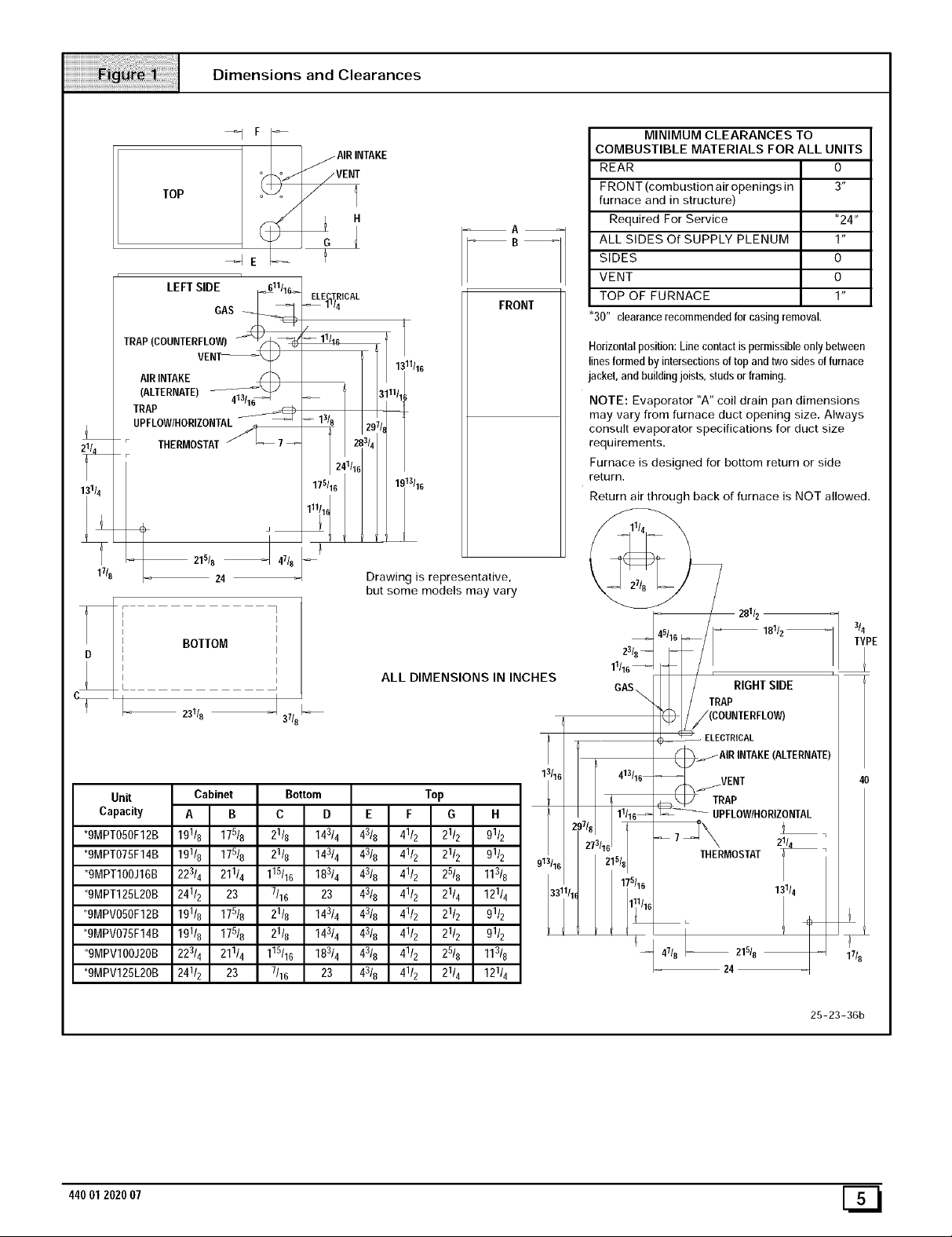
Dimensions and Clearances
TOP
LEFTSIDE F_611/1_
TRAI,_IIIIIrFvLEO_ - " I --
(ALTERNATE)13J_
;RA_OW/HORIZONTAi_
i
THermostAt/_7
i
31/4
i
21518 J 4718
1718
BOTTOM
23118 J 37/8
_I F
_e
GAS
24
COMBUSTIBLE MATERIALS FOR ALL UNITS
MINIMUM CLEARANCES TO
AIRINTAKE
REAR O
FRONT (combustion air openings in 3"
VENi
A
furnace and in structure)
Required For Service *24"
ALL SIDES Of SUPPLY PLENUM 1"
SIDES O
7
ELE TR CAL
_1_/4
/
_11/16
-B-1
FRONT
VENT O
TOP OF FURNACE 1"
"30" clearancerecommendedfor casingremoval.
Horizontalposition:Linecontactispermissibleonlybetween
linesformed by intersectionsoftopand twosidesoffurnace
jacket,andbuildingjoists,studs orframing.
NOTE: Evaporator "A" coil drain pan dimensions
may vary from furnace duct opening size. Always
consult evaporator specifications for duct size
requirements.
2 1/
Furnace is designed for bottom return or side
return.
Return air through back of furnace is NOT allowed.
Drawing is representative,
but some models may vary
2811z --
3/
T' E
23/8--
ALL DIMENSIONS IN INCHES
11116
GAS\
i / 18112
/(COUNTERFLOW)
( _ ELECTRICAL
/AIR INTAKE(ALTERNATE)
f._..IVENT
ZW__ ;_OWIHOR,ZONTAL
-- 7_THH_ERMOSTAT2_
13114
Unit
Capacity
*gMPT050F12B
*gMPT075F14B
*gMPT100J16B
*9MPT125L20B
13116 413116
}7/8 11116_
*9MPV050F12B
*9MPV075F14B
13 11_1/16
*9MPVIOOJ20B
*9MPV125L20B
25-23-36b
44001 2020 07 [_
T
17t8
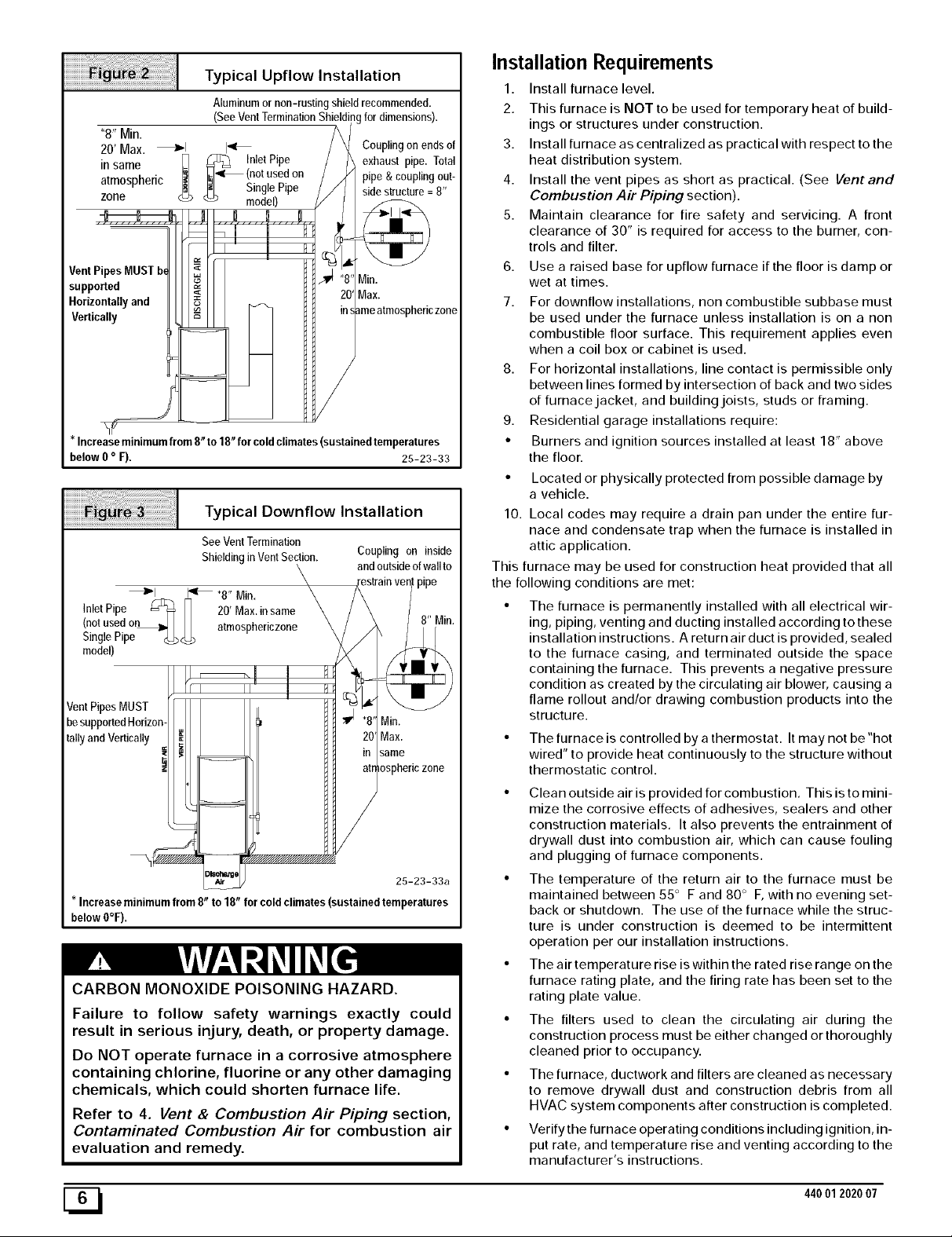
Typical Upflow Installation
Aluminum or non-rusting shield recommended.
(See Vent Termination Shielding for dimensions).
"8" Min.
20' Max. _1 I_
in same __ (notused on
atmospheric _iL. Single Pipe
zone _ model)
VentPipesMUST b_
supported
Horizontallyand
Vertically
Increaseminimumfrom8 to18 forcoldclimates(sustainedtemperatures
below0o F), 25-23-33
<_ _ InletPipe
Couplingon endsof
_iexhaust pipe. Total
pipe & couplingBut-
Typical Downflow Installation
See VentTermination
Shielding in Vent Section.
_1 _ "8" Min.
Inlet Pipe _ _ 20' Max.insame
(notused o_ _ atmosphedczone
Single Pipe_ <_
model)
VentPipes MUST
besupportedHorizon-
tallyand Vertically
* Increaseminimumfrom 8 to 18 forcoldclimates(sustained temperatures
below 0°F),
Coupling on inside
and outside of wall to
Min.
Max.
same
osphericzone
25-23-33a
CARBON MONOXIDE POISONING HAZARD.
Failure to follow safety warnings exactly could
result in serious injury, death, or property damage.
Do NOT operate furnace in a corrosive atmosphere
containing chlorine, fluorine or any other damaging
chemicals, which could shorten furnace life.
Refer to 4. Vent & Combustion Air Piping section,
Contaminated Combustion Air for combustion air
evaluation and remedy.
zone
Installation Requirements
1. Install furnace level.
2. This furnace is NOT to be used for temporary heat of build-
ings or structures under construction.
3. Install furnace as centralized as practical with respect to the
heat distribution system.
4. Install the vent pipes as short as practical. (See Vent and
Combustion Air Piping section).
5. Maintain clearance for fire safety and servicing. A front
clearance of 30" is required for access to the burner, con-
trols and filter.
6. Use a raised base for upflow furnace if the floor is damp or
wet at times.
7. For downflow installations, non combustible subbase must
be used under the furnace unless installation is on a non
combustible floor surface. This requirement applies even
when a coil box or cabinet is used.
8. For horizontal installations, line contact is permissible only
between lines formed by intersection of back and two sides
of furnacejacket, and buildingjoists, studs or framing.
9. Residential garage installations require:
• Burners and ignition sources installed at least 18" above
the floor.
• Located or physically protected from possible damage by
a vehicle.
10. Local codes may require a drain pan under the entire fur-
nace and condensate trap when the furnace is installed in
attic application.
This furnace may be used for construction heat provided that all
the following conditions are met:
• The furnace is permanently installed with all electrical wir-
ing, piping, venting and ducting installed according to these
installation instructions. A return air duct is provided, sealed
to the furnace casing, and terminated outside the space
containing the furnace. This prevents a negative pressure
condition as created by the circulating air blower, causing a
flame rollout and/or drawing combustion products into the
structure.
• The furnace is controlled by a thermostat. It may not be "hot
wired" to provide heat continuously to the structure without
thermostatic control.
• Clean outside air is provided for combustion. Thisisto mini-
mize the corrosive effects of adhesives, sealers and other
construction materials. It also prevents the entrainment of
drywall dust into combustion air, which can cause fouling
and plugging of furnace components.
• The temperature of the return air to the furnace must be
maintained between 55 ° F and 80 ° F, with no evening set-
back or shutdown. The use of the furnace while the struc-
ture is under construction is deemed to be intermittent
operation per our installation instructions.
• The air temperature rise iswithin the rated rise range on the
furnace rating plate, and the firing rate has been set to the
rating plate value.
• The filters used to clean the circulating air during the
construction process must be either changed or thoroughly
cleaned prior to occupancy.
• The furnace, ductwork and filters are cleaned as necessary
to remove drywall dust and construction debris from all
HVAC system components after construction is completed.
• Verify the furnace operating conditions including ignition, in-
put rate, and temperature rise and venting according to the
manufacturer's instructions.
[_ 440012020 07
Installation Positions
Leveling
This furnace can be installed in an upflow, horizontal (either left or
right) or downflow airflow position. DO NOT install this furnace on
its back. For the upflow position, the return air ductwork can be at-
tached to either the left or right side panel and/or the bottom. For
horizontal and downflow positions, the return air ductwork must be
attached to the bottom. The return air ductwork must never be at-
tached to the back of the furnace.
Furnace Installation Considerations
The installation of the furnace for a given application will dictate the
position of the furnace, the airflow, ductwork connections, vent and
combustion air piping. Consideration must be given to the follow-
ing:
Condensate Trap and Drain Lines
The supplied condensate trap must be attached to the furnace
side panel on either the left or right side. For horizontal installa-
tions, the drain trap is vertically attached to the side panel below
the furnace. A minimum clearance of 6" below the furnace is re-
quired for the condensate trap. Downward slope of the conden-
sate drain line from the condensate trap to the drain location must
be provided. Adequate freeze protection of the drain trap and the
drain line must be provided. See "Condensate Drain Trap"section
for further details.
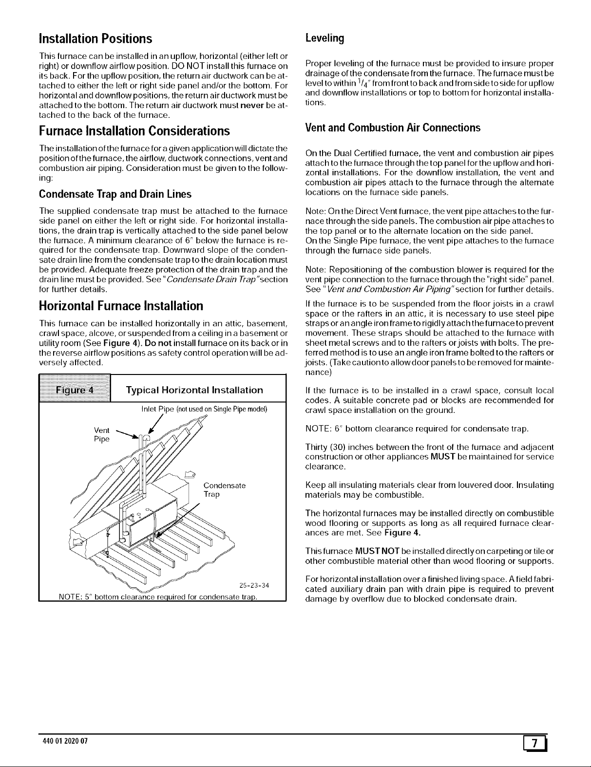
Horizontal Furnace Installation
This furnace can be installed horizontally in an attic, basement,
crawl space, alcove, or suspended from a ceiling in a basement or
utility room (See Figure 4). Do not install furnace on its back or in
the reverse airflow positions as safety control operation will be ad-
versely affected.
Proper leveling of the furnace must be provided to insure proper
drainage of the condensate from the furnace. The furnace must be
level to within 114"from front to back and from side to side for upflow
and downflow installations or top to bottom for horizontal installa-
tions.
Vent and Combustion Air Connections
On the Dual Certified furnace, the vent and combustion air pipes
attach to the furnace through the top panel for the upflow and hori-
zontal installations. For the downflow installation, the vent and
combustion air pipes attach to the furnace through the alternate
locations on the furnace side panels.
Note: On the Direct Vent furnace, the vent pipe attaches to the fur-
nace through the side panels. The combustion air pipe attaches to
the top panel or to the alternate location on the side panel.
On the Single Pipe furnace, the vent pipe attaches to the furnace
through the furnace side panels.
Note: Repositioning of the combustion blower is required for the
vent pipe connection to the furnace through the "right side" panel.
See "Vent and Combustion Air Piping"section for further details.
If the furnace is to be suspended from the floor joists in a crawl
space or the rafters in an attic, it is necessary to use steel pipe
straps or an angle iron frame to rigidly attach the furnace to prevent
movement. These straps should be attached to the furnace with
sheet metal screws and to the rafters or joists with bolts. The pre-
ferred method is to use an angle iron frame bolted to the rafters or
joists. (Take caution to allowdoor panels to be removed for mainte-
nance)
Typical Horizontal Installation
Inlet Pipe (notusedonSinglePipemodel)
Vent
Pipe
Condensate
Trap
25-23-34
NOTE: 5" bottom clearance required for condensate trap.
If the furnace is to be installed in a crawl space, consult local
codes. A suitable concrete pad or blocks are recommended for
crawl space installation on the ground.
NOTE: 6" bottom clearance required for condensate trap.
Thirty (30) inches between the front of the furnace and adjacent
construction or other appliances MUST be maintained for service
clearance.
Keep all insulating materials clear from Iouvered door. Insulating
materials may be combustible.
The horizontal furnaces may be installed directly on combustible
wood flooring or supports as long as all required furnace clear-
ances are met. See Figure 4.
This furnace MUST NOT be installed directly on carpeting or tile or
other combustible material other than wood flooring or supports.
For horizontal installation over a finished living space. A field fabri-
cated auxiliary drain pan with drain pipe is required to prevent
damage by overflow due to blocked condensate drain.
44001 2020 07 [_
3. Combustion 8, Ventilation Air
For Single Pipe Installation
(Non- Direct Vent)
CARBON MONOXIDE POISONING HAZARD
Failure to provide adequate combustion and
ventilation air could result in death and/or personal
injury.
Use methods described here to provide
combustion and ventilation air.
Furnaces require ventilation openings to provide sufficient air for
proper combustion and ventilation of flue gases. All duct or open-
ings for supplying combustion and ventilation air must comply with
National Fuel Gas Code, NFPA54/ANSI Z223.1, 2002 (or current
edition) and applicable provisions of local building codes.
Combustion and ventilation air must be supplied in accordance
with one of the following:
1. Section 8.3, Air for Combustion and Ventilation, ofthe Nation-
al Fuel Gas Code, National Fuel Gas Code (NFGC), ANSI
Z223.1-2002/NFPA 54-2002 in the U.S.,
2. Sections 7.2, 7.3, 7.5, 7.6, 7.7, and 7.8 of National Standard of
Canada, Natural Gas and Propane Installation Code
(NSCNGPIC), CSA B149.1-00 in Canada,
3. Applicable provisions of the local building code.
This furnace can NOT be common vented or connected to any
type B, BW or Lvent or vent connector, nor to any portion of a facto-
ry- built or masonry chimney. Ifthis furnace is replacing a previous-
ly common-vented furnace, it may be necessary to resize the
existing vent and chimney to prevent oversizing problems for the
other remaining appliance(s). See "Venting and Combustion Air
Check"in this section, This furnace MUST be vented to the out-
side.
When the installation is complete, check that all appliances have
adequate combustion air and are venting properly. See Venting
And Combustion Air Check in "5. Gas Vent Installation"Section in
this manual.
Outdoor Combustion Air Method
A space having less than 50 cubic feet per 1,000 BTUH input rating
for all gas appliances installed in the space requires outdoor air for
combustion and ventilation.
Air Openings andConnecting Ducts
1. Total maximum input ratings for all gas appliances in the
space MUST be considered when determining free area of
openings.
2. Connect ducts or openings directly to the outdoors.
3. When screens are used to cover openings, the openings
MUST be no smaller than 1/4" mesh.
4. The minimum dimension of air ducts MUST NOT be less
than 3".
5. When sizing grille, louver or screen, use the free area of
opening. If free area is NOT stamped or marked on grill or
louver, assume a 20 _ free area for wood and 60 _ for metal.
Screens shall have a mesh size not smaller than 1/4".
Requirements
1. Provide confined space with sufficient air for proper com-
bustion and ventilation of flue gases using horizontal or ver-
tical ducts or openings.
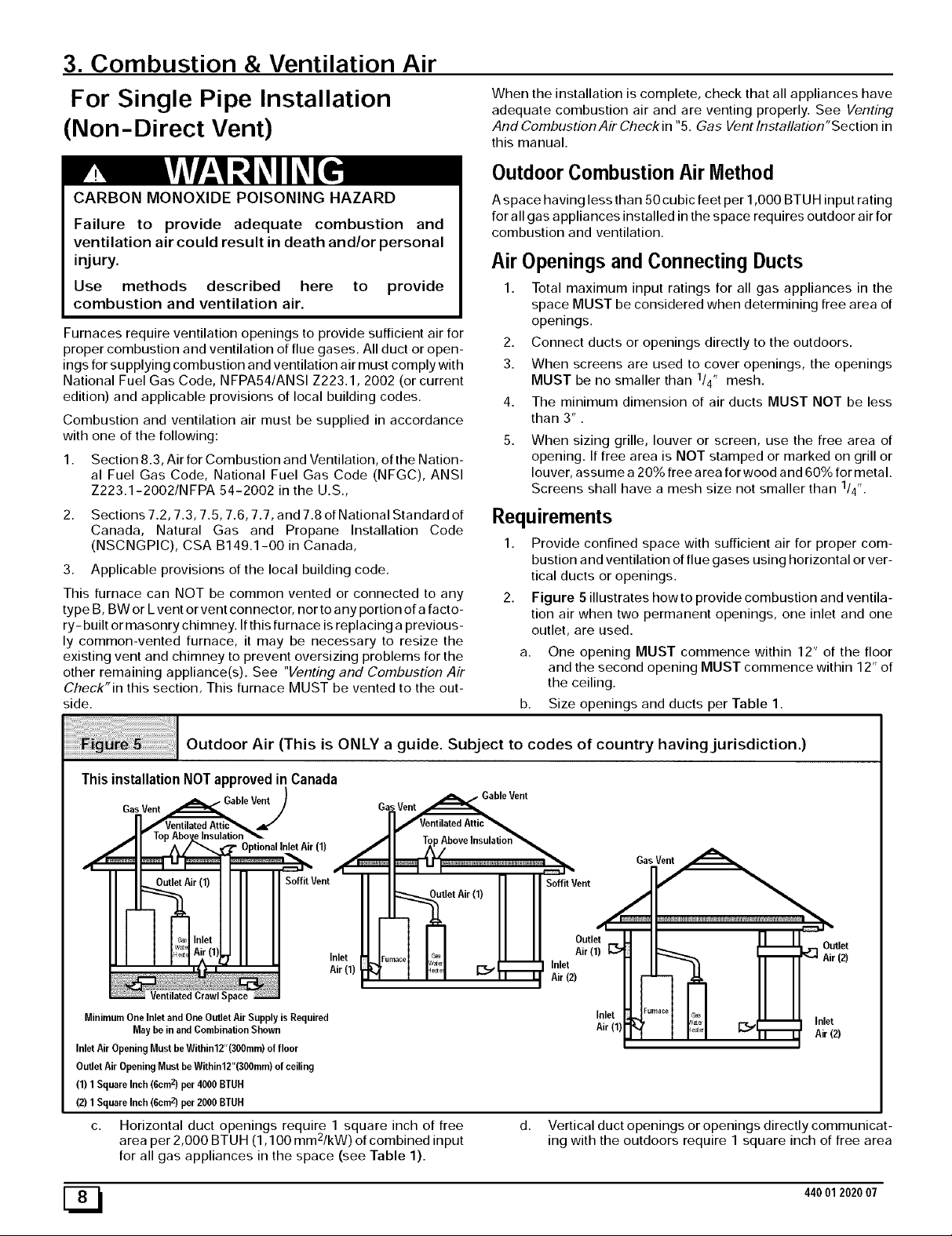
2. Figure 5 illustrates howto provide combustion and ventila-
tion air when two permanent openings, one inlet and one
outlet, are used.
a. One opening MUST commence within 12" of the floor
and the second opening MUST commence within 12" of
the ceiling.
b. Size openings and ducts per Table 1.
o o
Outdoor Air (This is ONLY a guide. Subject to codes of country having jurisdiction.)
ThisinstallationNOTapprovedin Canada
Gas Vent _able Ve_)
li'"-1 - I =:=J_
II I1 Soffit Vent
__ir (1) Soffit Vent
c_s Inlet
w_ Air (11 _ Inlet
I_÷ I Air(1)
Jentilated Crawl Space
Minimum One Inlet and One Outlet Air Supply is Required
May be in and Combination Shown
Inlet Air Opening Must be Within12"(300mm) of floor
Outlet Air Opening Must be Within12"(300mm) of ceiling
(1) 1 Square Inch (6cm z) per 4000 BTUH
(2) 1 Square Inch (6cm z) per 2000 BTUH
c. Horizontal duct openings require 1 square inch of free
a 2
rea per 2,000 BTUH (1,100 mm /kW) of combined input
for all gas appliances in the space (see Table 1).
F...... ('ia,_ L Air (1) _:_
r v_ _. Inlet
"_ _' _ _ Air (2)
11 Outlet
d. Vertical duct openings or openings directly communicat-
ing with the outdoors require 1 square inch of free area
ML
Inlet
Air(1)
:ld, I Eol Inlj] I r_=_l _ _ Airet(2)
44001 2020 07
per 4,000 BTU H (550 mm2/kW) for combined input of all
gas appliances in the space (see Table 1).
3. When one permanent outdoor opening is used, the opening
requires:
a. 1 sq. in of free area per 3,000 BTUH (700 mm2/kW) for
combined input of all gas appliances in the space (see
Table 1) and
b. not less than the sum of the areas of all vent connectors in
the space.
The opening shall commence within 12" of the top of the enclo-
sure. Appliances shall have clearances of at least 1" from the sides
and back and 6" from the front. The opening shall directly commu-
nicate with the outdoors or shall communicate through a vertical or
horizontal duct to the outdoors or spaces (crawl or attic) that freely
communicate with the outdoors.
iiiiiiiiiiiiiiiiiiiiiiiiiiiiiiiiiiiiiiiiiiiiiiiiiiiiiiiiiiiiii_!!_!i_!_:!_!_¸iii_iiiiiiiiiiii_iiiiii_!_i_i_i_i_i_i_i_i_i_i_i_i_i_i_i_i_i_i_i_i_i_i_i_i_i_i_i_i_i_i_i_ii_!ii!iiiii¸iiiiii
i
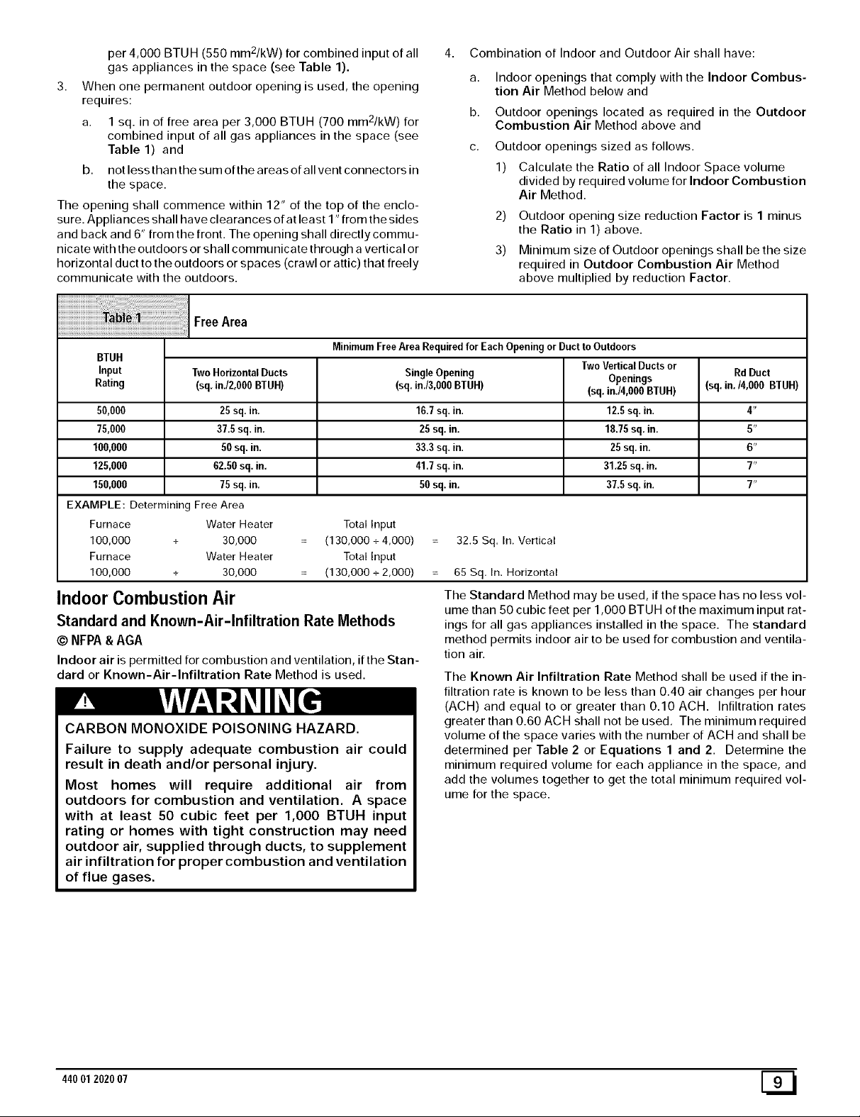
FreeArea
4. Combination of Indoor and Outdoor Air shall have:
a,
Indoor openings that comply with the Indoor Combus-
tion Air Method below and
b.
Outdoor openings located as required in the Outdoor
Combustion Air Method above and
C.
Outdoor openings sized as follows.
1) Calculate the Ratio of all Indoor Space volume
divided by required volume for Indoor Combustion
Air Method.
2) Outdoor opening size reduction Factor is 1 minus
the Ratio in 1) above.
3) Minimum size of Outdoor openings shall be the size
required in Outdoor Combustion Air Method
above multiplied by reduction Factor.
BTUH
Input Two HorizontalDucts SingleOpening Openings (sq.in./4,000 BTUH)
Rating (sq.inJ2,000 BTUH) (sq.in./3,000BTUH) (sq.in./4,000 BTUH)
50,000 25 sq.in. 16.7sq. in. 12.5sq. in. 4"
75,000 37.5sq. in. 25 sq. in. 18.75sq. in. 5"
100,000 50 sq. in. 33.3sq. in. 25 sq. in. 6"
125,000 62.50 sq. in. 41.7sq. in. 31.25 sq. in. 7"
150,000 75 sq. in. 50sq. in. 37.5sq. in. 7"
EXAMPLE: Determining Free Area
Furnace Water Heater Total Input
100,000 + 30,000 (130,000 + 4,000) 32.5 Sq. In. Vertical
Furnace Water Heater Total Input
100,000 + 30,000 (130,000 + 2,000) 65 Sq. In. Horizontal
Indoor Combustion Air
Standard and Known-Air-Infiltration Rate Methods
© NFPA&AGA
Indoor air is permitted for combustion and ventilation, if the Stan-
dard or Known-Air-Infiltration Rate Method is used.
CARBON MONOXIDE POISONING HAZARD.
Failure to supply adequate combustion air could
result in death and/or personal injury.
Most homes will require additional air from
outdoors for combustion and ventilation. A space
MinimumFree Area Requiredfor EachOpening or Ductto Outdoors
TwoVerticalDuctsor Rd Duct
The Standard Method may be used, if the space has no less vol-
ume than 50 cubic feet per 1,000 BTUH of the maximum input rat-
ings for all gas appliances installed in the space. The standard
method permits indoor air to be used for combustion and ventila-
tion air.
The Known Air Infiltration Rate Method shall be used if the in-
filtration rate is known to be less than 0.40 air changes per hour
(ACH) and equal to or greater than 0.10 ACH. Infiltration rates
greater than 0.60 ACH shall not be used. The minimum required
volume of the space varies with the number of ACH and shall be
determined per Table 2 or Equations 1 and 2. Determine the
minimum required volume for each appliance in the space, and
add the volumes together to get the total minimum required vol-
ume for the space.
with at least 50 cubic feet per 1,000 BTUH input
rating or homes with tight construction may need
outdoor air, supplied through ducts, to supplement
air infiltration for proper combustion and ventilation
of flue gases.
44001 2020 07 [_
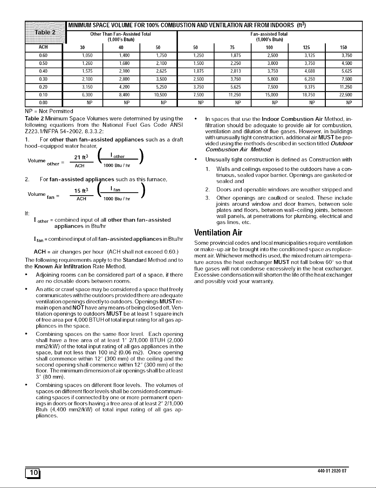
MINIMUMSPACEVOLUMEFOR100%COMBUSTIONANDVENTILATIONAIRFROMINDOORS(ft 3)
OtherThan Fan-AssistedTotal Fan-assistedTotal
(1,OOO'sBtuh)
ACH
0.60
0.50
0.40
0.30
0.20
0.I0
0.00
NP = Not Permitted
Table 2 Minimum Space Volumes were determined by using the
following equations from the National Fuel Gas Code ANSI
Z223.1/NFPA 54-2002, 8.3.3.2:
1. For other than fan-assisted appliances such as a draft
hood-equipped water heater,
Volume other - 21 ft3 _k I other )
2. For fan-assisted appliances such as this furnace,
Volume
If:
The following requirements apply to the Standard Method and to
the Known Air Infiltration Rate Method.
• Adjoining rooms can be considered part of a space, if there
• An attic or crawl space may be considered a space that freely
• Combining spaces on the same floor level. Each opening
• Combining spaces on different floor levels. The volumes of
fan
[ other = combined input of all other than fan-assisted
appliances in Btu/hr
[ fan = combined input of all fan-assisted appliances in Btu/hr
ACH = air changes per hour (ACH shall not exceed 0.60.)
are no closable doors between rooms.
communicates with the outdoors provided there are adequate
ventilation openings directly to outdoors. Openings MUST re-
main open and NOT have any means of being closed off. Ven-
tilation openings to outdoors MUST be at least I square inch
of free area per 4,000 BTU H of total input rating for all gas ap-
pliances in the space.
shall have a free area of at least 1" 2/1,000 BTUH (2,000
mm2/kW) of the total input rating of all gas appliances in the
space, but not less than 100 in2 (0.06 m2). Once opening
shall commence within 12" (300 ram) of the ceiling and the
second opening shall commence within 1 2" (300 ram) of the
floor. The minimum dimension of air openings shall be at least
3" (80 ram).
spaces on different floor levels shall be considered communi-
cating spaces if connected by one or more permanent open-
ings in doors or floors having a free area of at least 2" 2/1,000
Btuh (4,400 mm2/kW) of total input rating of all gas ap-
pliances.
30
1,050
1260
1,575
2,100
3,150
6,300
NP
I 40
1,400
1,680
2,100
2,800
4,200
8,400 10,500 7,500 11250 15,000
NP NP NP NP NP
/ \
ACH 1000Btu / hr
15 ft 3 _, I fan
ACH 1000 Btu / hr
/
50
1,750
2,100
2,625
3,500
5,250
)
(1,000'sBtuh)
50
1250
1,500
1,875
2,500
3,750
In spaces that use the Indoor Combustion Air Method, in-
filtration should be adequate to provide air for combustion,
ventilation and dilution of flue gases. However, in buildings
with unusually tight construction, additional air MUST be pro-
vided using the methods described in section titled Outdoor
Combustion Air Method:
• Unusually tight construction is defined as Construction with
1. Walls and ceilings exposed to the outdoors have a con-
2. Doors and openable windows are weather stripped and
3. Other openings are caulked or sealed. These include
75
1,875
2,250
2,813
3,750
5,625
tinuous, sealed vapor barrier. Openings are gasketed or
sealed and
joints around window and door frames, between sole
plates and floors, between wall-ceiling joints, between
wall panels, at penetrations for plumbing, electrical and
gas lines, etc.
100
2,500
3,000
3,750
5,000
7,500
125
3,125
3,750
4,688
6,250
9,375
18,750
NP
150
3,750
4,500
5,625
7,500
11250
22,500
Ventilation Air
Some provincial codes and local municipalities require ventilation
or make-up air be brought into the conditioned space as replace-
ment air. Whichever method is used, the mixed return air tempera-
ture across the heat exchanger MUST not fall below 60 ° so that
flue gases will not condense excessively in the heat exchanger.
Excessive condensation will shorten the life of the heat exchanger
and possibly void your warranty.
NP
[_ 440012020 07
Venting and Combustion Air Check
The following information is supplied to allow the installer to make
adjustments to the setup of existing appliances, IF REQUIRED,
based on good trade practices, local codes, and good judgement
of the installer. Manufacturer does NOT take responsibility for
modifications made to existing equipment.
NOTE: If this installation replaces an existing furnace from a
commonly vented system, the original venting system may no lon-
ger be sized to properly vent the attached appliances. An improp-
erly sized venting system may cause the formation of condensate
in the vent and the leakage or spillage of vent gases. To make sure
there is adequate combustion air for all appliances, MAKE THE
FOLLOWING CHECK.
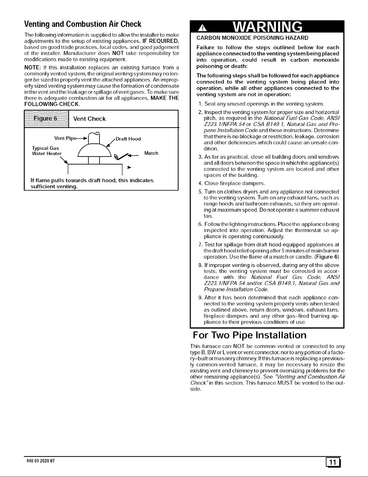
Vent Check
,,-,q
Vent Pipe--'_l I_ S Draft Hood
Typical Gas f "_
Water Heater ( I I %Vii...._ Match
I I
If flame pulls towards draft hood, this indicates
sufficient venting.
CARBON MONOXIDE POISONING HAZARD
Failure to follow the steps outlined below for each
appliance connected to the venting system being placed
into operation, could result in carbon monoxide
poisoning or death:
The following steps shall be followed for each appliance
connected to the venting system being placed into
operation, while all other appliances connected to the
venting system are not in operation:
1. Seal any unused openings in the venting system.
2. Inspect the venting system for proper size and horizontal
pitch, as required in the National Fuel Gas Code, ANSI
Z223. 1/NFPA 54 or CSA B149.1, Natural Gas and Pro-
pane Installation Code and these instructions. Determine
that there is no blockage or restriction, leakage, corrosion
and other deficiencies which could cause an unsafe con-
dition.
3. As far as practical, close all building doors and windows
and all doors between the space in which the appliance(s)
connected to the venting system are located and other
spaces of the building.
4. Close fireplace dampers.
5. Turn on clothes dryers and any appliance not connected
to the venting system. Turn on any exhaust fans, such as
range hoods and bathroom exhausts, so they are operat-
ing at maximum speed. Do not operate a summer exhaust
fan.
6. Followthe lighting instructions. Placethe appliance being
inspected into operation. Adjust the thermostat so ap-
pliance is operating continuously.
7. Test for spillage from draft hood equipped appliances at
the draft hood relief opening after 5 minutes of main burner
operation. Use the flame of a match or candle. (Figure 6)
8. If improper venting is observed, during any of the above
tests, the venting system must be corrected in accor-
dance with the National Fuel Gas Code, ANSI
Z223.1/NFPA 54 and/or CSA B149. 1, Natural Gas and
Propane Installation Code.
9. After it has been determined that each appliance con-
nected to the venting system properly vents when tested
as outlined above, return doors, windows, exhaust fans,
fireplace dampers and any other gas-fired burning ap-
pliance to their previous conditions of use.
For Two Pipe Installation
This furnace can NOT be common vented or connected to any
type B, BW or Lvent or vent connector, nor to a ny portion of a facto-
ry-built or masonry chimney. If this furnace is replacing a previous-
ly common-vented furnace, it may be necessary to resize the
existing vent and chimney to prevent oversizing problems for the
other remaining appliance(s). See "Venting and Combustion Air
Check"in this section, This furnace MUST be vented to the out-
side.
44001 2020 07 [_1
4. Vent and Combustion Air Piping
CARBON MONOXIDE POISONING HAZARD.
Failure to properly vent this furnace could result in
death and/or personal injury.
Use methods described here to provide combustion
and ventilation air.
Dual Certified (*9MPT & *9MPV Models)
This furnace is certified as a category IV appliance and is fan as-
sisted. A catefory IV appliance is a direct vent central furnace
which operates with a positive vent static pressure and a flue loss
less than 17%. This furnace can be installed as a direct vent fur-
nace using outside air for combustion or the furnace can use air
from inside the structure for combustion. The INLET air pipe is op-
tional. If combustion air comes from inside the structure, adequate
make up air MUST be provided to compensate for oxygen burned.
See Confined Space Installation in the Combustion and Ven-
tilation Air chapter. If combustion air is drawn from outside the
structure, it MUST be taken from the same atmospheric pressure
zone as the vent pipe.
Contaminated Combustion Air
Installations in certain areas or types of structures could cause ex-
cessive exposure to contaminated air having chemicals or halo-
gens that will result in safety and performance related problems
and may harm the furnace. These instances must use only out-
door air for combustion.
The following areas or types of structures may contain or have ex-
posure to the substances listed below. The installation must be
evaluated carefully as it may be necessary to provide outdoor air
for combustion.
• Commercial buildings.
• Buildings with indoor pools.
• Furnaces installed in laundry rooms.
• Furnaces installed in hobby or craft rooms.
• Furnaces installed near chemical storage areas.
• Permanent wave solutions for hair.
• Chlorinated waxes and cleaners.
• Chlorine based swimming pool chemicals.
• Water softening chemicals.
• De-icing salts or chemicals.
• Carbon tetrachloride.
• Halogen type refrigerants.
• Cleaning solvents (such as perchloroethylene).
• Printing inks, paint removers, varnishes, etc..
• Hydrochloric acid.
• Sulfuric Acid.
• Solvent cements and glues.
• Antistatic fabric softeners for clothes dryers.
• Masonry acid washing materials.
Ventand Combustion Air Piping Guidelines
This furnace is approved for venting with Schedule 40 PVC,
CPVC, ABS, Cellular Core pipe fittings and SDR-26 PVC.
NOTE: All PVC, CPVC, ABS, and Cellular Core pipe fittings, sol-
vent cement, primers and procedures must conform to American
National Standard Institute and American Society for Testing and
Materials (ANSI/ASTM) standards.
• Pipe and Fittings (in Italics)- ASTM D1785, D2241,
D2466, D2661, D2665, F-891, F-628.
• PVC Primer and Solvent Cement (in Italics)- ASTM
D2564.
• Procedure for Cementing Joints (in Italics)- Ref ASTM
D2855.
NOTE: All vent piping MUST be installed in compliance with local
codes or ordinances, these instructions, good trade practices, and
codes of country having jurisdiction.
1. Determine the best routing and termination for the vent pipe
and air inlet pipe by referring to all of the instructions and
guidelines in this Section.
2. Determine the size required for the vent pipe and air inlet
pipe.
3. Loosely assemble all venting parts without adhesive (pipe
joint cement) for correct fit before final assembly.
4. Use of vertical piping is preferred because there will be
some moisture in the flue gases that may condense as it
leaves the vent pipe (See Speciallnstruction ForHorizontal
Vents).
5. The vertical vent pipe MUST be supported so that no weight
is allowed to rest on the combustion blower.
6. Exhaust vent piping or air inlet piping diameter MUST NOT
be reduced.
7. All exhaust vent piping from the furnace to termination
MUST slope upwards. A minimum of 1/4" per foot of run is
required to properly return condensate to the furnace drain
system.
8. Use DWV type long radius elbows whenever possible, as
they provide for the minimum slope on horizontal runs and
they provide less resistance in the vent system. If DWV el-
bows cannot be used, use two, 45 ° elbows when possible.
On horizontal runs the elbows can be slightly misaligned to
provide the correct slope.
9. All horizontal pipe runs MUST be supported at least every
five feet with galvanized strap or other rust resistant materi-
al. NO sags or dips are permitted.
10. All vertical pipe runs MUST be supported every six feet
where accessible.
11. The maximum pipe length is 40' total in the inlet oroutlet
side of the system. Upto five, 90° elbows can be used on the
inlet orthe outlet. With the Concentric Vent Termination Kits
(NAHAO01CV or NAHAOO2CV), the maximum pipe length
is 35' with 4 90° elbows. If more elbows are required, reduce
the length of both the inlet and exhaust pipes 5' for each
additional elbow used. (See Table 3 or Table 4).
12. The minimum pipe run length is 2'.
13. The piping can be run in the same chase or adjacent to sup-
ply or vent pipe for water supply or waste plumbing. It can
also be run in the same chase with a vent from another 90+
furnace.
NOTE: In NO case can the piping be run in a chase where
temperatures can exceed 140 ° F. or where radiated heat
from adjacent surfaces would exceed 140 ° F.
14. The vent outlet MUST be installed to terminate in the same
atmospheric pressure zone as the combustion air inlet.
15. The vent system can be installed in an existing unused
chimney provided that:
• Both the exhaust vent and air intake run the length of the
chimney.
• No other gas fired appliance or fireplace (solid fuel) is
vented into the chimney.
44001 2020 07
• The top of the chimney MUST be sealed flush or crowned
up to seal against rain or melting snow so ONLY the piping
protrudes.
• The termination clearances shown in Figure 7 are main-
tained.
16. Furnace applications with vertical vents requiring vent di-
ameter increaser fittings must have increaser fittings
installed in vertical portion of the vent. Condensate will be
trapped in the vent if the vent diameter is increased prior to
having an elbow turned upward. This could cause nuisance
tripping of the pressure switch.
Piping InsulationGuidelines
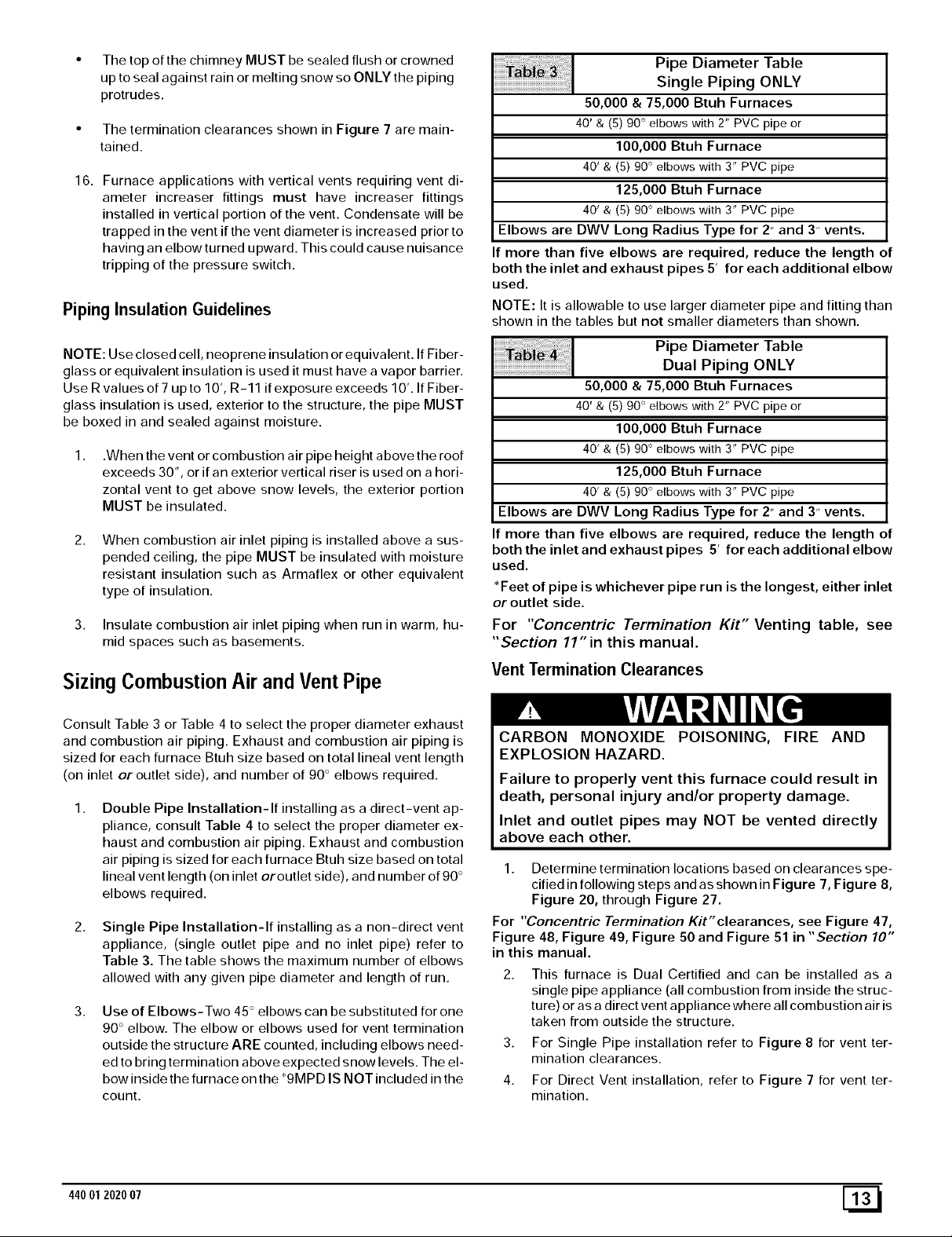
Pipe Diameter Table
Single Piping ONLY
50,000 & 75,000 Btuh Furnaces
40' & (5) 90 ° elbows with 2" PVC pipe or
100,000 Btuh Furnace
40' & (5) 90° elbows with 3" PVC pipe
125,000 Btuh Furnace
40' & (5) 90° elbows with 3" PVC pipe
Elbows are DWV Long Radius Type for 2" and 3" vents.
If more than five elbows are required, reduce the length of
both the inlet and exhaust pipes 5' for each additional elbow
used.
NOTE: It is allowable to use larger diameter pipe and fitting than
shown in the tables but not smaller diameters than shown.
NOTE: Use closed cell, neoprene insulation or equivalent. If Fiber-
glass or equivalent insulation is used it must have a vapor barrier.
Use Rvalues of 7 upto 10', R-11 if exposure exceeds 10'. If Fiber-
glass insulation is used, exterior to the structure, the pipe MUST
be boxed in and sealed against moisture.
1,
.When the vent or combustion air pipe height above the roof
exceeds 30", or if an exterior vertical riser is used on a hori-
zontal vent to get above snow levels, the exterior portion
MUST be insulated.
2,
When combustion air inlet piping is installed above a sus-
pended ceiling, the pipe MUST be insulated with moisture
resistant insulation such as Armaflex or other equivalent
type of insulation.
3. Insulate combustion air inlet piping when run in warm, hu-
mid spaces such as basements.
Sizing Combustion Air andVentPipe
Consult Table 3 or Table 4 to select the proper diameter exhaust
and combustion air piping. Exhaust and combustion air piping is
sized for each furnace Btuh size based on total lineal vent length
(on inlet or outlet side), and number of 90 ° elbows required.
1,
Double Pipe Installation-If installing as a direct-vent ap-
pliance, consult Table 4 to select the proper diameter ex-
haust and combustion air piping. Exhaust and combustion
air piping is sized for each furnace Btuh size based on total
lineal vent length (on inlet oroutlet side), and number of 90 °
elbows required.
2,
Single Pipe Installation-If installing as a non-direct vent
appliance, (single outlet pipe and no inlet pipe) refer to
Table 3. The table shows the maximum number of elbows
allowed with any given pipe diameter and length of run.
3, Use of Elbows-Two 45° elbows can be substituted for one
90 ° elbow. The elbow or elbows used for vent termination
outside the structure ARE counted, including elbows need-
ed to bring termination above expected snow levels. The el-
bow inside the furnace on the *9MPD IS NOT included in the
count.
Ta_i _ Pipe Diameter Table
Dual Piping ONLY
50,000 & 75,000 Btuh Furnaces
40' & (5) 90 ° elbows with 2" PVC pipe or
100,000 Btuh Furnace
40' & (5) 90° elbows with 3" PVC pipe
125,000 Btuh Furnace
40' & (5) 90° elbows with 3" PVC pipe
Elbows are DWV Long Radius Type for 2" and 3" vents.
If more than five elbows are required, reduce the length of
both the inlet and exhaust pipes 5' for each additional elbow
used.
*Feet of pipe is whichever pipe run is the longest, either inlet
or outlet side.
For "Concentric Termination Kit" Venting table, see
"Section 11" in this manual.
Vent Termination Clearances
CARBON MONOXIDE POISONING, FIRE AND
EXPLOSION HAZARD.
Failure to properly vent this furnace could result in
death, personal injury and/or property damage.
Inlet and outlet pipes may NOT be vented directly
above each other.
1. Determine termination locations based on clearances spe-
cified in following steps and as shown in Figure 7, Figure 8,
Figure 20, through Figure 27.
For "Concentric Termination Kit" clearances, see Figure 47,
Figure 48, Figure 49, Figure 50 and Figure 51 in "Section 10"
in this manual.
This furnace is Dual Certified and can be installed as a
single pipe appliance (all combustion from inside the struc-
ture) or as a direct vent appliance where all combustion air is
taken from outside the structure.
3. For Single Pipe installation refer to Figure 8 for vent ter-
mination clearances.
4. For Direct Vent installation, refer to Figure 7 for vent ter-
mination.
44001 202007 [_
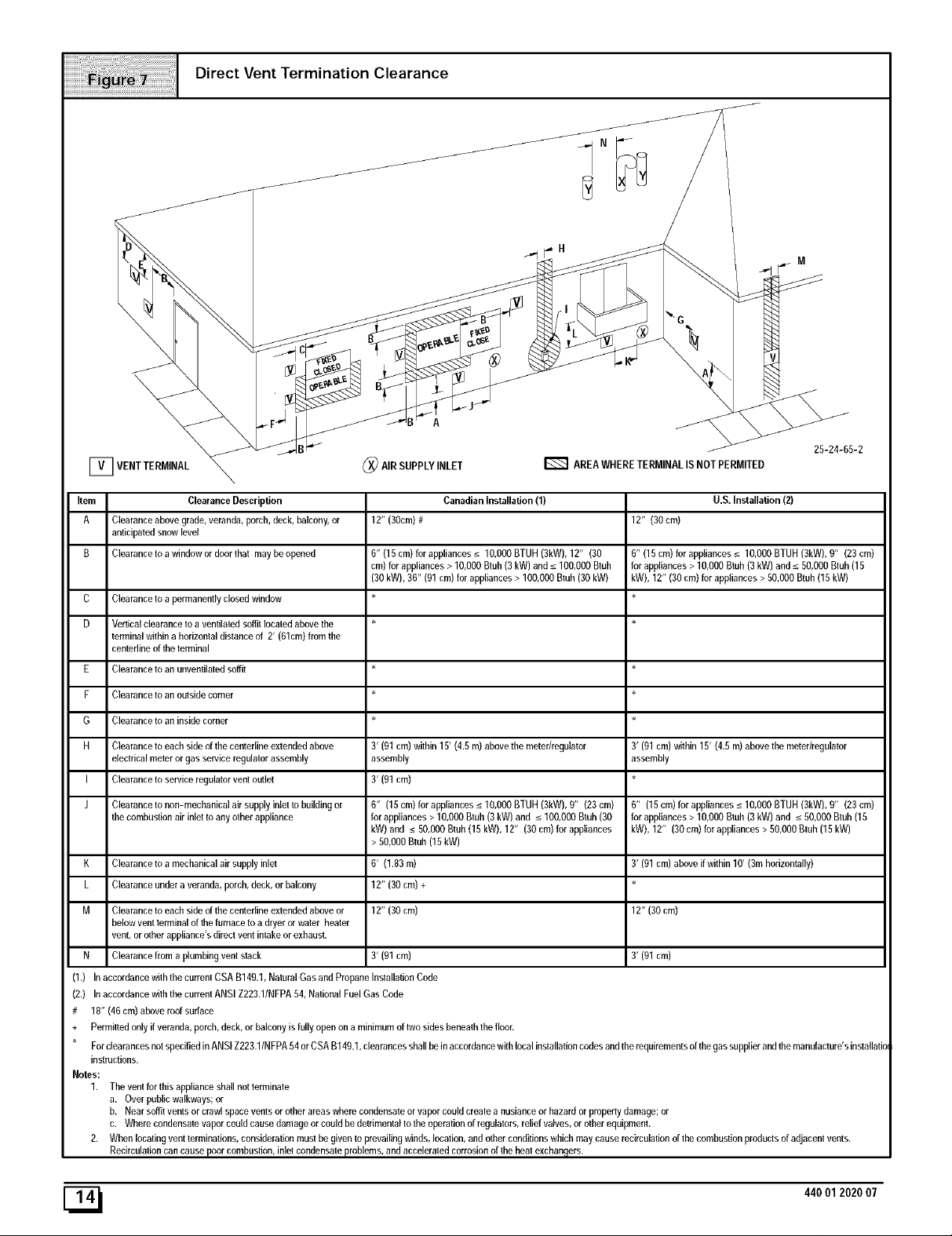
Item Clearance Description
A Clearance above grade, veranda, porch, deck, balcony, or
anticipated snow level
B Clearance to a window or door thai may be opened
C Clearance to a permanently closed window
D Vertical clearance to a ventilated soffit located above the
terminal within a horizontal distance of 2' (61cm) from the
centedine of the terminal
E Clearance to an unventilated soffit
P Clearance to an outside corner
G Clearance to an inside comer
H Clearance to each side of the centefline extended above
electrical meter or gas service regulator assembly
I Clearance to service regulator vent outlet
J Clearance to non-mechanical air supply inlet _o building or
the combustion air inlet to any other appliance
Canadian Installation (1)
12" (30cm)#
6" (15 cm) for appliances _< 10,000 BTUH (3kW), 12" (30
cm) for appliances > 10,000 Btuh (3 kW) and _<100,000 Btuh
(30 kW), 36" (91 cm) for appliances > 100,000 Btub (30 kW)
3' (91 cm) within 15' (4.5 m) above the meter/regulator
assembly
3' (91 cm)
6" (15cm)forappliances_<10,000BTUH(3kW),0" (23cm)
forappliances> 10,000Btuh (3 kW) and _<100,000Btuh(30
kW) and _<50,000Btuh(15kW), 12" (30 cm)for appliances
12" (30cm)
6" (15 cm) for appliances _< 10,000 BTUH (3kW), 0" (23 cm)
for appliances > 10,000 Bmh (3 kW) and _<50,000 Btuh (15
kW), 12" (30 cm) for appliances > 50,000 Btuh (15 kW)
3' (91 cm) within 15' (4.5 m) above the meter/regulator
assembly
6" (15cm)forappliances_<lO,OOOBTUH (3kW),O" (23cm)
for appliances > 10,000 Btuh (3 kW) and _<50,000 Btuh (15
kW), 12" (30 cm) for appliances > 50,000 Bluh (15 kW)
U.S. Installation (2)
> 50,000Bmh(15kW)
K Clearance to a mechanical air supply inlet
L Clearance under a veranda, porch, deck, or balcony
M Clearance to each side of the centefline extended above or
below vent terminal of the furnace to a dryer or water heater
vent, or other appliance's direct vent intake or exhaust.
N Clearance from a plumbing vent stack 3' (91 cm)
(1.) In accordance with the currem CSA B149.1, Natural Gas and Propane Installation Code
(2,) In accordance w0h the current ANSI Z223.1/NFPA 54, National Fuel Gas Code
# 18" (46 cm) above roof surface
+ Permitted only if veranda, porch, deck, or balcony is fully open on a minimum of two sides beneath the floor.
For deara nces not specified in AN SI Z223.1/N FPA 54 or CSA B149,1, clearances shall be in accordance with local installation codes and the requirements of the gas supplier and the manufacture's installatie
instructions.
Notes:
1. The vent for this appliance shall not terminate
a. Over public walkways; or
b. Near soffit vents or crawl space vents or other areas where condensate or vapor could create a nusiance or hazard or property damage; or
c. Where condensate vapor could cause damage or could be detrimental to the operation of regulalors, relief valves, or other equipment.
2. When locating vent lerminations, consideration must be given to prevailing winds, location, and other conditions which may cause recirculation of the combustion products of adjacent vents.
Recircula0on can cause poor combustion, inlet condensate problems, and accelerated corrosion of the heal exchangers.
6' (1.83m)
12" (30 cm) +
12" (30 cm)
3' (91 cm) above if within 10' (3m horizontally)
12" (30 cm)
3' (91 cm)
[_ 440012020 07
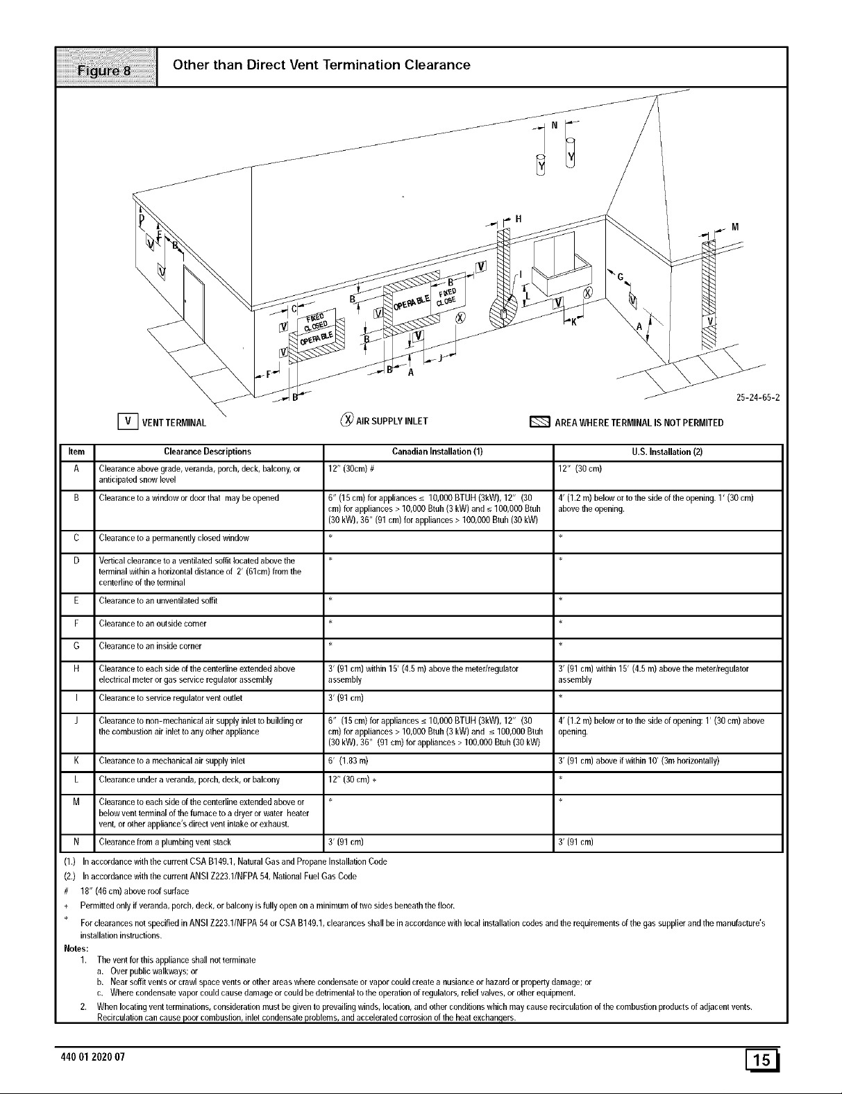
Other than Direct Vent Termination Clearance
Item Clearance Descriptions
A Clearance above grade, veranda, porch, deck, balcony, or
anticipated snow level
B Clearance to a window or door thai may be opened
C
Clearance to a permanently closed window
D
Vertical clearance to a ventilated soffit located above the *
terminal within a horizontal distance of 2' (61cm) from the
centerline of the terminal
Clearance to an unventilated soffit *
F Clearance to an outside corner *
G Clearance to an inside comer *
H Clearance to each side of the centedine extended above
eleclrical meter or gas service regulator assembly
I Clearance to service regulator vent outlet
J Clearance to non-mechanical air supply inlel to building or
the combustion air inlet to any other appliance
K Clearance to a mechanical air supply inlel
L Clearance under a veranda, porch, deck, or balcony
M Clearance to each side of the centedine extended above or *
below vent terminal of the furnace to a dryer or water heater
vent, or other appliance's direct vent intake or exhaust.
N Clearance from a plumbing vent stack
(1.) In accordance with the current CSA B149.1, Natural Gas and Propane Installation Code
(2.) In accordance wilh the current ANSI Z223.1/NFPA 04, National Fuel Gas Cede
# 18" (46 cm) above roof surface
+ Permitted only if veranda, porch, deck, or balcony is fully open on a minimum of two sides beneath the floor.
For clearances not specified in ANSI Z223.1/NFPA 04 or CSA B140.1, clearances shall be in accordance with local installalion codes and the requirements of the gas supplier and the manufacture's
installation instructions.
Notes:
1. The vent for this appliance shall not terminale
a. Over public walkways; or
b. Near soffit vents or crawl space venta or other areas where condensate or vapor could create a nusiance or hazard or property damage; or
c. Where condensate vapor could cause damage or could be detrimental to the operafion of regulalors, relief valves, or other equipmenL
2. When locating vent terminations, consideration must be given to prevailing winds, location, and other conditions which may cause recirculation of the combustion products of adjacent vents.
Recirculafion can cause poor combustion, inlet condensate problems, and acceleraled corrosion of the heat exchangers.
12" (30cm)#
0" (10 cm) for appliances _< 10,000 BTUH (3kW), 12" (30
cm) for appliances > 10,000 Btuh (3 kW) and _<100,000 Btuh
(30 kW), 30" (01 cm) for appliances > 100,000 Btuh (30 kW)
3' (91 cm) within 15' (4.5 m) above the meter/regulator
assembly
3' (91 cm)
6" (15cm)forappliances_<10,OOOBTUH(3kW),12" (30
cm)forappliances> 10,000Btuh(3kW) and _<100,000Btuh
(30 kW),30" (91 cm) for appliances> 100,000Btuh(30 kW)
6' (1.83m)
12" (30 cm) +
3' (91 cm)
Canadian Installation (1)
U.S.Installation(2)
12" (30cm)
4' (1.2 m) below or to the side of the opening, 1' (30 cm)
above the opening.
3' (01 cm) within 15' (4.5 m) above the meter/regulator
assembly
4' (1.2 m) below or to the side of opening: 1' (30 cm) above
opening.
3' (91 cm) above if within 10' (3m horizontally)
3' (91 cm)
44001 202007
CondensateDrainTrap
This furnace removes both sensible and latent heat from the prod-
ucts of combustion. Removal of the latent heat results in con-
densation of the water vapor. The condensate is removed from the
furnace through the drains in the plastic transition and the vent fit-
ting. The drains connect to the factory installed internally mounted
condensate drain trap on the left or right side of the furnace.
The startup of a new furnace will involve a cycle or two of the fur-
nace to properly prime the condensate trap with water. Until the
trap is fully primed, some condensate will be pulled into the com-
bustion blower. The furnace may cycle on the pressure switch con-
nected to the plastic transition box due to condensate buildup.
After the trap is primed, the condensate will start draining from the
furnace. The combustion blower will clear out any remaining con-
densate in the blower housing through the vent fitting downstream
of the blower. Note that the condensate trap can also be primed by
pouring water into the 1/2" drain hose. Remove the1/2" ID drain
hose from either the gutter or the white PVC Tee Trap. Using a fun-
nel pour eight (8) ounces of water into 1/2" ID drain hose.Water will
flow through the drain hose and into the condensate drain trap.
This will prime both the vent and the transition sides of the trap. Re-
connect the 1/2, ID drain hose to the original component, either the
gutter or the PVC Tee Trap.
The condensate drain trap supplied with the furnace MUST be
used. The drain connection on the condensate drain trap is sized
for 3/4" PVC or CPVC pipe, however alternate 1/2" CPVC (nominal
5/8" O.D.) or vinyl tubing with a minimum inner diameter (I.D.) of
5/8" may also be used, as allowed by local codes. Alternate drain
pipes and hoses may be used as allowed by local codes.
The drain line must maintain a 1/4" per foot downward slopetoward
the drain. 1/4" per foot is recommended. Installation of an overflow
line is recommended when the 1/4" per foot slope to the conden-
sate drain cannot be maintained. See Figure 18 for proper routing
and installation of the overflow.
DO NOT trap the drain line in any other location than at the con-
densate drain trap supplied with the furnace.
If possible DO NOT route the drain line where it may freeze. The
drain line must terminate at an inside drain to prevent freezing of
the condensate and possible property damage.
A condensate sump pump MUST be used if required by lo-
cal codes, or if no indoor floor drain is available. The con-
densate pump must be approved for use with acidic
condensate.
2. A plugged condensate drain line or a failed condensate
pump will allow condensate to spill. If the furnace is installed
where a condensate spill could cause damage, it is recom-
mended that an auxiliary safety switch be installed to pre-
vent operation of the equipment in the event of pump failure
or plugged drain line. If used, an auxiliary safety switch
should be installed in the R circuit (low voltage) ONLY.
3. If the auxiliary switch in the condensate pump is used, the
furnace may shut down dueto a blocked condensate line or
failed pump. To prevent frozen water pipes see the "Frozen
Water Pipe Hazard" section on Page 4 of this manual.
FROZEN AND BURST WATER PIPE HAZARD
Failure to do so could result in burst water pipes,
serious property damage and/or personal injury.
If a condensate pump is installed, a plugged
condensate drain or a failed pump may cause the
furnace to shut down. Do not leave the home
unattended during freezing weather without turning
off water supply and draining water pipes or
otherwise protecting against the risk of frozen pipes.
Condensate Drain Trap Freeze Protection
Special precautions MUST be made if installing furnace in an area
which may drop below freezing. This can cause improper opera-
tion or damage to the equipment. If the the furnace environment
has the potential of freezing, the drain trap and drain line must be
protected. Use 3 to 6 watt per foot at 115 volt, 40 ° F self-regulating
shielded and waterproof heat tape. Wrap the drain trap and drain
line with the heat tape and secure with the ties. Follow the heat
tape manufacturer's recommendations.
[_ 440012020 07
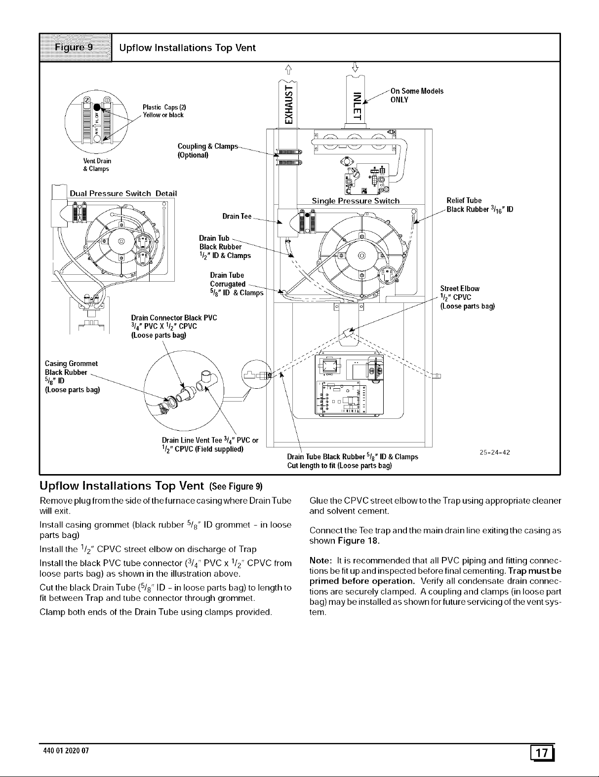
Upflow Installations Top Vent
/On Some Models
ONLY
Vent Drain
& Clamps
Dual Pressure Switch Detail
_ __ Drainfub_
"_ _ _/_ sis" ID
_] DrainConnector Black PVC
p_],==l / 3/4"PVCX l/z" CPVC
Casing Grommet
BlackRubber
s/8" ID
(Looseparts bag)
(Looseparts bag)
(Optional)
Corrugate
\
Drain LineVentTee314"PVC or
1/2"CPVC(Field supplied)
Drain TubeBlack Rubbers/8" ID &Clamps
Cut length to fit (Loose partsbag)
25-24-42
Upflow Installations Top Vent (SeeFigure 9)
Remove plug from the side of the furnace casing where Drain Tu be
will exit.
Install casing grommet (black rubber 5/8" ID grommet - in loose
parts bag)
Install the 1/2" CPVC street elbow on discharge of Trap
Install the black PVC tube connector (3/4" PVC x 1/2" CPVC from
loose parts bag) as shown in the illustration above.
Cut the black Drain Tube (5/8" ID - in loose parts bag) to length to
fit between Trap and tube connector through grommet.
Clamp both ends of the Drain Tube using clamps provided.
44001 202007 [_
Glue the CPVC street elbow to the Trap using appropriate cleaner
and solvent cement.
Connect the Tee trap and the main drain line exiting the casing as
shown Figure 18.
Note: It is recommended that all PVC piping and fitting connec-
tions be fit up and inspected before final cementing. Trap must be
primed before operation. Verify all condensate drain connec-
tions are securely clamped. A coupling and clamps (in loose part
bag) may be installed as shown for future servicing of the vent sys-
tem.
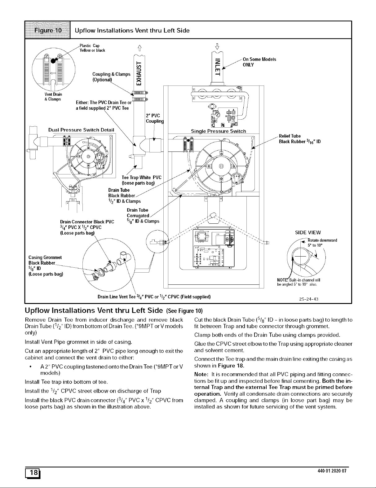
Upflow Installations Vent thru Left Side
/Plastic Cap
Yelloworblack
Coupling & Clamps
VentDrain
&Clamps Either:ThePVC DrainTee or
afield supplied 2" PVCTee
\
On SomeModels
ONLY
Dual Pressure Switch Detail_
CasingGrommet
s/{' ID
(Loosepartsbag)
DrainTube
BlackRubbel
1/2"ID& Clamps
DrainConnector BlackPVC
3/4"PVCX 1/2"CPVC
(Loosepartsbag)
DrainLineVentTee /4 PVC or /2 CPVC (Fieldsupplied)
TeeTrapWhite PVC
(loosepartsbag)
DrainTube
s/{' ID& Clamps
3 t_ 1 n
Sin qle Pressure Switch
BlackRubber3/16"ID
SIDE VIEW
FF_otate downward
NOTF. Buell-in channel will
be angled 5° to 10° also.
25-24-43
Upflow Installations Vent thru Left Side (SeeFigure10)
Remove Drain Tee from inducer discharge and remove black
Drain Tube (1/2" ID) from bottom of Drain Tee. (*9MPT or V models
only)
Install Vent Pipe grommet in side of casing.
Cut an appropriate length of 2" PVC pipe long enough to exit the
cabinet and connect the vent drain to either:
• A 2" PVC coupling fastened onto the Drain Tee (*9MPT or V
models)
Install Tee trap into bottom of tee.
Install the 112" CPVC street elbow on discharge of Trap
Install the black PVC drain connector (3/4" PVC x 1/2" CPVC from
loose parts bag) as shown in the illustration above.
[_ 440012020 07
Cut the black Drain Tube (5/8" ID - in loose parts bag) to length to
fit between Trap and tube connector through grommet.
Clamp both ends of the Drain Tube using clamps provided.
Glue the CPVC street elbow to the Trap using appropriate cleaner
and solvent cement.
Connect the Tee trap and the main drain line exiting the casing as
shown in Figure 18.
Note: It is recommended that all PVC piping and fitting connec-
tions be fit up and inspected before final cementing. Both the in-
ternal Trap and the external Tee Trap must be primed before
operation. Verify all condensate drain connections are securely
clamped. A coupling and clamps (in loose part bag) may be
installed as shown for future servicing of the vent system.
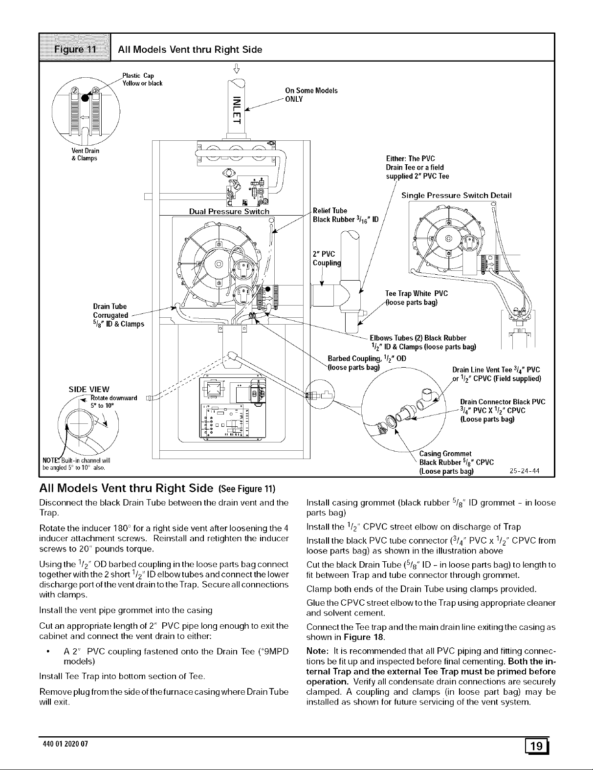
All Models Vent thru Right Side
On Some Models
VentDrain
& Clamps
Drain Tube
Corrugated
sl8" ID & Clamps
SIDE VIEW
/_Rotat e downward
Dual Pressure Switch
,ReliefTube
BlackRubber3/16"ID
Barbed Cot
Either:The PVC
Drain Teeor a field
supplied 2" PVC Tee
Single Pressure Switch Detail
TeeTrapWhite PVC
Elbows Tubes (2) Black Rubber
1/2" ID & Clamps (loose parts bag)
I, llz" OD
Drain Line Vent Tee 3/4" PVC
CPVC (Field supplied)
DrainConnector Black PVC
PVCX 1/2"CPVC
(Loosepartsbag)
NOTE'r. Built-in channel will
he angled 5° to 10° also.
All Models Vent thru Right Side (SeeFigure 11)
Disconnect the black Drain Tube between the drain vent and the
Trap.
Rotate the inducer 180 ° for a right side vent after loosening the 4
inducer attachment screws. Reinstall and retighten the inducer
screws to 20" pounds torque.
Using the /2' OD barbed coupling in the loose parts bag connect
together with the 2 short /2' ID elbowtubes and connect the lower
discharge port of the vent drain to the Trap. Secure all connections
with clamps.
Install the vent pipe grommet into the casing
Cut an appropriate length of 2" PVC pipe long enough to exit the
cabinet and connect the vent drain to either:
• A 2" PVC coupling fastened onto the Drain Tee (_9MPD
Install Tee Trap into bottom section of Tee.
Remove plug from the side of the furnace casing where Drain Tube
will exit.
1 ,
1 ,
models)
Grommet
BlackRubber5/8"CPVC
(Loosepartsbag) 25-24-44
Install casing grommet (black rubber 5/8" ID grommet - in loose
parts bag)
Install the 1/2" CPVC street elbow on discharge of Trap
Install the black PVC tube connector ( /4' PVC x 1/2" CPVC from
3 ,
loose parts bag) as shown in the illustration above
Cut the black Drain Tube (5/8" ID - in loose parts bag) to length to
fit between Trap and tube connector through grommet.
Clamp both ends of the Drain Tube using clamps provided.
Glue the CPVC street elbow to the Trap using appropriate cleaner
and solvent cement.
Connect the Tee trap and the main drain line exiting the casing as
shown in Figure 18.
Note: It is recommended that all PVC piping and fitting connec-
tions be fit up and inspected before final cementing. Both the in-
ternal Trap and the external Tee Trap must be primed before
operation. Verify all condensate drain connections are securely
clamped. A coupling and clamps (in loose part bag) may be
installed as shown for future servicing of the vent system.
44001 2020 07 [_
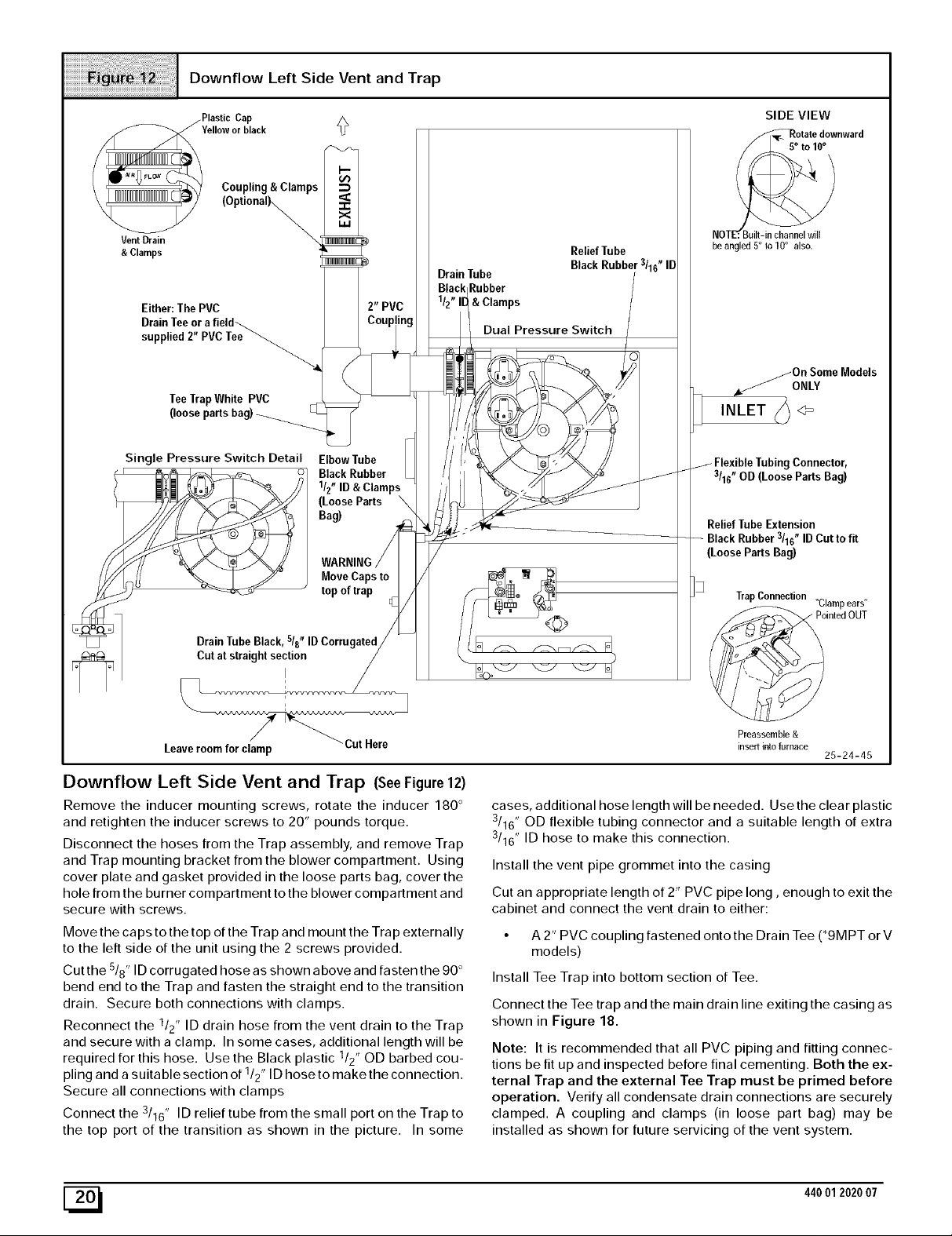
Downflow Left Side Vent and Trap
Cap
Yellowor black
Coupling & Clamps
VentDrain
&Clamps
(Optionally,,
Either: The PVC
TeeTrapWhite PVC
(looseparts
Single Pressure Switch Detail Elbow Tube
1/2"ID& Clamps
(LooseParts \
Bag)
BlackRubber
WARNING
MoveCaps to
top of trap
DrainTube
Rubber
& Clamps
Dual Pressure Switch
Relief Tube
SIDE VIEW
_o otatedownward
o 10°
NOT_
be angled 5° to10° also.
/On SomeModels
,/ONLY
INLET h 4=
Connector,
3/16" OD (Loose Parts Bag)
Relief Tube Extension
Rubber 3/16" ID Cut to fit
(Loose Parts Bag)
TrapConnection "Clampears"
DrainTubeBlack, sis" IDCorrugated
Cut at straight section
I
Leaveroom for clamp
Cut Here
Downflow Left Side Vent and Trap (SeeFigure 12)
Remove the inducer mounting screws, rotate the inducer 180 °
and retighten the inducer screws to 20" pounds torque.
Disconnect the hoses from the Trap assembly, and remove Trap
and Trap mounting bracket from the blower compartment. Using
cover plate and gasket provided in the loose parts bag, cover the
hole from the burner compartment to the blower compartment and
secure with screws.
Move the caps to the top of the Trap and mount the Trap externally
to the left side of the unit using the 2 screws provided.
Cut the 5/8" ID corrugated hose as shown above and fasten the 90 °
bend end to the Trap and fasten the straight end to the transition
drain. Secure both connections with clamps.
Reconnect the 1/2" ID drain hose from the vent drain to the Trap
and secure with a clamp. In some cases, additional length will be
required for this hose. Use the Black plastic 1/2" OD barbed cou-
pling and a suitable section of 1/2" ID hose to make the connection.
Secure all connections with clamps
Connect the 3/16" ID relief tube from the small port on the Trap to
the top port of the transition as shown in the picture. In some
ointedOUT
Preassemble &
insert into furnace
25-24-45
cases, additional hose length will be needed. Use the clear plastic
3/16" OD flexible tubing connector and a suitable length of extra
3/16" ID hose to make this connection.
Install the vent pipe grommet into the casing
Cut an appropriate length of 2" PVC pipe long, enough to exit the
cabinet and connect the vent drain to either:
• A 2" PVC coupling fastened onto the Drain Tee (*9MPT or V
models)
Install Tee Trap into bottom section of Tee.
Connect the Tee trap and the main drain line exiting the casing as
shown in Figure 18.
Note: It is recommended that all PVC piping and fitting connec-
tions be fit up and inspected before final cementing. Both the ex-
ternal Trap and the external Tee Trap must be primed before
operation. Verify all condensate drain connections are securely
clamped. A coupling and clamps (in loose part bag) may be
installed as shown for future servicing of the vent system.
[_ 440012020 07
Downflow Right Side Vent and Trap
Vent Drain
& Clamps
SIDE VIEW
_Rotate downward
NOTE'r. Built-in channel will
he angled 5° to 10° also.
Single Pressure Switch Detail
Elbow Tube BlackRubber
1/2"ID &Clamps
(LoosePartsBag)
BarbedCoupling
1/2"OD
(Loose Parts Bag)
Dual Switch
Relief Tube
Black Rubber
3116" ID
Drain Tube
Black Rubber
1/2" ID Cut to Fi
Trap Connection
Preassemble &
insert inlo furnace
Coupling & Clamps
(Optional)
Either: ThePVC
Drain Teeor a field
DrainTubeCorrugated
s/8"ID& Clamps
Downflow Right Side Vent and Trap (SeeFigure 13)
Remove the Drain Tee if installed.
Disconnect the hoses from the Trap assembly, and remove Trap
and Trap mounting bracket from the blower compartment. Using
cover plate and gasket provided in the loose parts bag, cover the
hole from the burner compartment to the blower compartment and
secure with screws.
Move the caps to the top of the Trap and mount the Trap externally
to the right side of the unit using the 2 screws provided.
Connect the corrugated Drain Tube from the transition box to the
Trap as shown. If an extension is required, use the black PVC tube
connector and the black 5/8" ID Drain Tube in the loose parts bag.
Cut tube to length. Secure all connections with clamps.
Connect the drain hose from the Vent Drain to the Trap. If an ex-
tension is required, use the black 1/2" OD barbed coupling, con-
nect a black 1/2" ID elbow tube and a suitable section of a 1/2" ID
TeeTrapWhite PVC
(loosepartsbag)
MoveCaps to topof trap
DrainTube Black Rubber
_"ID Cutto Fit & Clamps
(LooseParts Bag)
25-24-46
drain tube to make connection from the vent drain to the trap. Se-
cure all connections with clamps.
Install the vent pipe grommet into the casing
Cut an appropriate length of 2" PVC pipe long, enough to exit the
cabinet and connect the vent drain to either:
• A 2" PVC coupling fastened onto the Drain Tee (*9MPT or V
models)
Install Tee Trap into bottom section of Tee.
Connect the Tee trap and the main drain line exiting the casing as
shown in Figure 18.
Note: It is recommended that all PVC piping and fitting connec-
tions be fit up and inspected before final cementing. Both the ex-
ternal Trap and the external Tee Trap must be primed before
operation. Verify all condensate drain connections are securely
clamped. A coupling and clamps (in loose part bag) may be
installed as shown for future servicing of the vent system.
44001 2020 07 [_

Horizontal Left Thru Top
VentDrain
& Clamps
Plastic Caps
Alternate Orienation
]
Dual Pressure Switch
D___
Single Pressure Switch Detail
ReliefTube
BlackRubber
," ID
f
Trap Connection
_ "Clamp ears"
Pointed OUT
Preassemble &
insert into furnace
_o
-_ Field
Supplied Tee
TeeTrapWhite PVC
(looseparts bag)
Coupling & Clamps
(Optional)
CapandClamp
Open End
Drain Tube
Black Rubber
1/2" ID & Clamps
Horizontal Left-Thru Top (SeeFigure14)
Disconnect the hoses from the Trap assembly, and remove Trap
and Trap mounting bracket from the blower compartment. Using
cover plate and gasket provided in the loose parts bag, cover the
hole from the burner compartment to the blower compartment and
secure with screws.
Mount the Trap externally to the bottom side of the unit using the
2 screws provided in the location shown.
Cut the corrugated tube as shown in the illustration above. Con-
nect the corrugated hose from the transition to the Trap. Secure
connections with clamps.
Remove the black 1/2" ID Drain Tube from the Drain Tee. Install
a yellow cap and clamp over the open drain port of the Drain Tee.
Connect the black 1/2" ID Drain Tube from the Vent Drain to the
Trap. Secure connections with clamps.
Connect the 3/16" ID relief tube to the middle port on the Trap. If an
extension is required, use the 3/16" OU flexible tubing connector
/' /Cut to Fit (Loose Parts Bag)
f,
DrainTubeCorrugated /8 ID& Clamps
Cut at straight section
_Cut Here
Leaveroomfor clamp
and the black 3/16" ID relief tube in the loose parts bag. Cut tube
to length. Secure all connections with clamps.
Cut an appropriate length of 2" PVC pipe, long enough to exit the
cabinet and connect the vent drain to either:
• A 2" PVC coupling fastened onto the Drain Tee (*9MPT or V
models)
Install Tee Trap into bottom section of Tee.
Connect the Tee trap and the main drain line exiting the casing as
shown in Figure 18.
Note: It is recommended that all PVC piping and fitting connec-
tions be fit up and inspected before final cementing. Both the ex-
ternal Trap and the external Tee Trap must be primed before
operation. Verify all condensate drain connections are securely
clamped. A coupling and clamps (in loose part bag) may be
installed as shown for future servicing of the vent system.
I
25-24-47
[_ 44001 2020 07

Horizontal Left-Side Vent
Single Pressure Switch Detail
Alternate Orienation
f P,as,icCap
T_ 7/ /'_/l _ J // -" _]IL Yellow or black
I Dual pr essuRriiST_tthRlack ,u h_ // &Clamps
I 1o / zElb°""beBlac.rubber
/ I I 10_ / _ _ 1/2" ID & Clamps (Loose Parts Bag)
Tee Trap White !V_ _ ,'__BarbedCouplingl/2 "OD
h I I ©'_==_ .L DraintubeBUckrubber
// \ ,,
Flex,bleTubm Connector / / _' _ DrainTubeCorru atedS/8 ID&Clam s
3116"OD (Loo_geParts Bag_// BR;_icekf i_ubbErX_n,s,'_ W_ARNING_ _ut at straight section P
Cutto Fit (LooslSpartsBag) Move Capsto _._ i
Horizontal Left- Side Vent (SeeFigure 15)
Remove the Drain Tee from the Vent Drain if installed (*9MPD
models only)
Rotate the inducer 180 ° for a side vent after loosening the 4 induc-
er attachment screws. Reinstall and retighten the inducer screws
to 20" pounds torque.
Disconnect the hoses from the Trap assembly, and remove Trap
and Trap mounting bracket from the blower compartment. Using
cover plate and gasket provided in the loose parts bag, cover the
hole from the burner compartment to the blower compartment and
secure with screws.
Mount the Trap externally to the bottom side of the unit using the
2 screws provided in the location shown.
Cut the corrugated tube as shown in the illustration above. Con-
nect the corrugated hose from the transition to the Trap. Secure
connections with clamps.
Connect the black 1/2" ID Drain Tube from the Vent Drain to the
Trap. If an extension is required, use the black 1/2" OD flexible tub-
ing connector and the black 1/2" ID Drain Tube in the loose parts
bag. Cut tube to length. Secure connections with clamps.
Connect the 3/16" ID relief tube to the middle port on the Trap. If an
extension is required, use the 3116"0D flexible tubing connector
CI t°p°ftrap Leave_ I
25-24-48
and the black 3/16" ID relief tube in the loose parts bag. Cut tube
to length.
Cut an appropriate length of 2" PVC pipe, fittings and extension
pipe long enough to exit the cabinet and connect the vent drain to
either:
• A 2" PVC coupling fastened onto the Drain Tee (*9MPT or V
models)
Install Tee Trap into bottom section of Tee.
Important: The pipe to the Tee Trap must be level or sloping to-
wards the Tee Trap
Connect the Tee trap and the main drain line exiting the casing as
shown in Figure 18.
Note: It is recommended that all PVC piping and fitting connec-
tions be fit up and inspected before final cementing. Both the ex-
ternal Trap and the external Tee Trap must be primed before
operation. Verify all condensate drain connections are securely
clamped. A coupling and clamps (in loose part bag) may be
installed as shown for future servicing of the vent system.
A coupling and clamps (in loose part bag) may be installed as
shown for future servicing of the vent system.
44001 202007 [_

Horizontal Right thru Top
TrapConnection
Preassemble&
insertintofurnace
"Clampears" Alternate Orienation
Single Pressure Switch Detail
Yelloworblack
PlasticCap
ElbowTube Black Rubber _
1/2"ID &Clamps VentDrain
(LoosePartsBag) &Clamps
WARNING \ Coupling & Clamps
Add Cap andClamp \ (Op!ional) Field....
\\ \/ _ buppaeu zee
ReliefTubeBlackRubber3/ls"lO _ _ _ _ J
_ __ _ TeeTrap
FlexibleTubingConnector _"_/ _ _ _/White PVC
BlackRubber3/ls"lD __' _-__ _ _ _ _ [_ I h_
Cutto Fit (LoosePartsBag) __" =_,__ _' II_EI_- INLET
__/ _ _]- _ _ On SomeModels
_) _/r____' _ _ "_L _ ONLY
Cut at straight section I / | DrainTubeBlackRubber
_ / 1/2 ID&Clamps
Leaveroom forclamp _ - -
• J'_ _"_ Cut Here | 25 24 49
Horizontal Right Thru Top (SeeFigure 16)
Disconnect the hoses from the Trap assembly, and remove Trap
and Trap mounting bracket from the blower compartment. Using
cover plate and gasket provided in the loose parts bag, cover the
hole from the burner compartment to the blower compartment and
secure with screws.
Mount the Trap externally to the bottom side of the unit using the
2 screws provided in the location shown.
Cut the corrugated tube as shown in the illustration above. Con-
nect the corrugated hose from the transition to the Trap. Secure
connections with clamps.
Connect the black 1/2" ID Drain Tube from the Vent Drain to the
Trap. If an extension is required, use the black 1/2" OD barbed
coupling and the black 1/2" ID Drain Tube in the loose parts bag.
Cut tube to length. Secure connections with clamps.
Connect the 3/16" ID relief tube to the middle port on the Trap. If
an extension is required, use the clear 3/16" OD flexible tubing con-
nector and the black /16' ID relief tube in the loose parts bag. Cut
3
tube to length.
Cut an appropriate length of 2" PVC pipe, fittings and extension
pipe long enough to exit the cabinet and connect the vent drain to
a standard field supplied 2" PVC tee
Install Tee Trap into bottom section of Tee.
Connect the Tee trap and the main drain line exiting the casing as
shown in Figure 18.
Note: It is recommended that all PVC piping and fitting connec-
tions be fit up and inspected before final cementing. Both the ex-
ternal Trap and the external Tee Trap must be primed before
operation. Verify all condensate drain connections are securely
clamped. A coupling and clamps (in loose part bag) may be
installed as shown for future servicing of the vent system.
[_ 440012020 07

HorizontalRight-SideVent
Single Pressure Switch Detail
ReliefTubeBlack Rubber
3/16"ID
FlexibleTubingConnector
3/16"OD (LoosePartsBag)_/
ReliefTubeExtension_f
Black Rubber3/16"ID
Cut to Fit (LooseParts Bag)
Elbow Tube BlackRubber
1/2"ID& Clamps
(LooseParts
Plastic Cap
Yellow or black
VentDrain
&Clamps
Level or Sloped
towards Tee
Coupling & Clamps
(Optional)
/
Field
/ SuppliedTee
TeeTrapWhitePVC
_/(loose partsbag)
BarbedCoupling 1/2"OD
(LooseParts Bag)
Some Models ONLY
Alternate Orienation
Dual Pressure Switch
Drain Tube Corrugated
Cut at straight section
Leaveroomfor clamp _Cut Here
Horizontal Right Side Vent (SeeFigure17)
Disconnect Drain Tee if installed (*9MPD models only)
Disconnect the hoses from the Trap assembly, and remove Trap
and Trap mounting bracket from the blower compartment. Using
cover plate and gasket provided in the loose parts bag, cover the
hole from the burner compartment to the blower compartment and
secure with screws.
Mount the Trap externally to the bottom side of the unit using the
2 screws provided in the location shown.
Cut the corrugated tube as shown in the illustration above. Con-
nect the corrugated hose from the transition to the Trap. Secure
connections with clamps.
Connect the black 1/2" ID Drain Tube from the Vent Drain to the
Trap. If an extension is required, use the 1/2" OD barbed coupling
and the black 1/2" ID Drain Tube in the loose parts bag. Cut tube
to length. Secure connections with clamps.
Connect the 3/16" ID relief tube to the middle port on the Trap. If
an extension is required, use the clear /16' OU splice connector
3 ,
DrainTubeBlackRubber
l/z" ID& Clamps
25-24-50
and the black 3/16" ID relief tube in the loose parts bag. Cut tube
to length.
Cut an appropriate length of 2" PVC pipe, fittings and extension
pipe long enough to exit the cabinet and connect the vent drain to
either:
• A 2" PVC coupling fastened onto the Drain Tee (*9MPT or V
models)
Install Tee Trap into bottom section of Tee.
Important: The pipe to the Tee Trap must be level or sloping to-
wards the Tee Trap
Connect the Tee trap and the main drain line exiting the casing as
shown in Figure 18.
Note: It is recommended that all PVC piping and fitting connec-
tions be fit up and inspected before final cementing. Both the ex-
ternal Trap and the external Tee Trap must be primed before
operation. Verify all condensate drain connections are securely
clamped. A coupling and clamps (in loose part bag) may be
installed as shown for future servicing of the vent system.
44001 2020 07 1_

Connecting Tee Trap to Condensate
Trap and Main Drain Line
4_
Important: Prime both traps with water before operation.
Failure to prime the traps may result in discharge of flue gases
from the condensate drain line and open tee for a period of
time, and may result in temporary lockout of the furnace upon
start up. Main drain line construction is left to the discretion of
the installer. It may be made of either ridged pipe or flexible
tube. Tube ID should NOT be less than 1/2,,.
Connecting Vent and Combustion Air Piping
Open Tee
\
Evaporator
Coil
Drain Line
(Optm_
Main Drain Line
The Tee Trap must be connected to the main condensate drain
line as conceptually shown above. Different installations may
require slightly different orientations. The following steps apply
to all installations.
1.
The Tee Trap should be installed as close to the side or top
of the furnace as practical. Minimize the distance between
the inducer and the Tee Trap as much as possible.
2.
An open tee is to be used at the Tee Trap discharge. The top
end of the tee should be open to the atmosphere to elimi-
nate potential air lock problems.
3.
The drain line from the Tee Trap is to be connected to the
furnace condensate trap drain line as shown above.
4.
Condensate drain lines from a cooling coil may be con-
nected downstream of the connection point of the Tee Trap
and Furnace Condensate Trap.
Condensate
Trap
25-24-41N
CARBON MONOXIDE POISONING HAZARD I
Failure to properly seal vent piping could result in I
death, personal injury and/or property damage. I
Cement or mechanically seal all joints, fittings, etc. I
to prevent leakage of flue gases. I
Refer to Figure 9 through Figure 17 that corresponds to the
installation position of the furnace for the application.
Preassernble the vent and combustion air piping from the furnace
to the vent termination. Do not cement the pipe joints until the pipe
preassembly process is complete.
Combustion Air Pipe Connection (Dual Certified or
Direct Vent)
Install the air intake coupling and gasket to the furnace with the
four(4) screws.
Note: The air intake cou piing and gasket ca n be installed to the top
panel to the alternate air intake locations on either the left or right
side panels of the furnace.
For downflow installation, the air intake coupling and gasket must
be installed to the alternate air intake location on either the left or
right side panels. Remove the 3" hole plug from the side panel and
relocate to the air intake hole in the top panel. Use four screws to
seal the four(4) mounting holes in the top panel next to the hole
plug. Drill four(4) 7/64" diameter holes in the casing using the air
intake coupling as the template.
The air intake coupling is sized for 2" PVC pipe.
Install the combustion air pipe to the air intake coupling using RTV
sealant to provide for future serviceability.
Vent Pipe Connection
Install the vent pipe grommet to the furnace panel. Locate the
grommet in the furnace panel at a location directly away from the
vent fitting on the combustion blower. The grommet snaps into the
3" hole plug from the furnace panel. NOTE: Depending on the
installation position, the vent pipe grommet will be installed to the
top panel or to the alternate location on the side panels. If needed,
remove the 3" hole plug from the furnace panel and relocate to the
open hole in the furnace panel. (See Figure 9 or Figure 18)
Install the vent pipe to the rubber coupling, the vent fitting or the
PVC vent extension pipe. Securely attach using the clamp or PVC
cement as required.
Note: The vent fitting MUST be installed with the air flow
marking arrow pointed toward the vent pipe. (See Figure 19)
Some installations require the vent fitting to be installed with
a 5° to 10 ° downward slope. (See Figure 9 thru Figure 18)
I
I
I
I_ 44001 202007

Proper Sealing Procedure for
Combustion Blower
RubberCoupling j _, VentPipe
&Clamps-___ _(Top PanelExit)
D_.o _ NOTE: The 90 ° elbow is approved
.r.pe for use inside the furnace ONLY.
90° Elbow
& Clamps
Combustion
Pipe(Side Panel
Exit)
SIDE VIEW
Tee
NOTE:Built-in channelwill beangled5° to 10° also.
ate downward
25-24-14a
Joining Pipe and Fittings
FIRE HAZARD
Failure to do so could result in personal injury
and/or property damage.
Observe all cautions and warnings printed on
material containers
Provide adequate ventilation and do NOT assemble
near heat source or open flame. Do NOT smoke
while using solvent cements and avoid contact with
skin or eyes.
This furnace is approved for venting with Schedule 40 PVC,
CPVC, ABS, Cellular Core pipe fittings and SDR-26 PVC.
NOTE: All PVC, CPVC, ABS, and Cellular Core pipe fittings, sol-
vent cement, primers and procedures MUST conform to American
National Standard Institute and American Society for Testing and
Materials (ANSI/ASTM) standards.
Pipe and Fittings - ASTM D1785, D2241, D2466, D2661,
D2665, F-891, F-628
• PVC Primer and 5olvent Cement - ASTM D2564
• Procedure for Cementing Joints - Ref ASTM D2855
NOTE: In order to create a seal that allows future removal of pipe,
RTV sealant MUST be used on the inlet pipe where itjoins to the
furnace. PVC, CPVC, ABS, and Cellular Core pipe and cement
may be used on all other joints.
CARBON MONOXIDE POISONING HAZARD
Failure to follow this warning could result in
personal property damage, injury or death.
Do NOT use solvent cement that has become
curdled, lumpy or thickened and do NOT thin.
Observe precautions printed on containers. For
applications below 32 ° F., use only low temperature
type solvent cement. Poor joints may lead to
disconnected or leaking vent pipe joints allowing
carbon monoxide to enter the living space.
1. Cut pipe end square, remove ragged edges and burrs.
Chamfer end of pipe, then clean fitting, socket and pipe joint
of all dirt, grease, or moisture.
NOTE: Stir the solvent cement frequently while using. Use a natu-
ral bristle brush or the dauber supplied with the cement. The prop-
er brush size is one inch.
2. After checking pipe and socket for proper fit, wipe socket
and pipe with cleaner-primer. Apply a liberal coat of primer
to inside surface of socket and outside of pipe. Do NOT al-
low primer to dry before applying cement.
3. Apply a thin coat of cement evenly in the socket. Quickly ap-
ply a heavy coat of cement to the pipe end and insert pipe
into fittings with a slight twisting movement until it bottoms
out.
NOTE: Cement MUST be fluid while inserting pipe. If NOT, recoat
pipe.
4. Hold the pipe in the fitting for 30 seconds to prevent the ta-
pered socket from pushing the pipe out of the fitting.
5. Wipe all excess cement from the joint with a rag. Allow 15
minutes before handling. Cure time varies according to fit,
temperature and humidity.
Connecting Vent Pipes and Termination
NOTE: Combustion air intake and vent MUST terminate in the
same atmospheric pressure zone. If installation is in a cold climate
(sustained temperatures below 0° F), increase the minimum dis-
tance between vent pipe and air intake from 8" to 18".
CARBON MONOXIDE POISONING HAZARD.
Failure to properly vent this furnace could result
in death, personal injury and/or property damage.
Maintain a minimum of 36" between combustion
air inlet and clothes dryer vent. Terminate the
combustion air intake as far as possible from any
air conditioner, heat pump, swimming pool,
swimming pool pumping, chlorinator or filtration
unit.
Install all couplings, nipples and elbows using proper proce-
dures for Joining Pipe and Fittings and maintain spacing
between vent and combustion air piping as indicated in
Figure 20 through Figure 27.
44001 2020 07 [_

SidewallTermination12"orMore
AboveSnowLevelorGradeLevel
8"* "18"Minimumfor coldclimates
MIN.
MIN.
GRADE LEVEL 25-00-05F
OR
SNOW LEVEL
(substainedbelow0° F)
Sidewall Termination with Exterior
Risers to Get Above Snow Level or Grade
:::::::::::::::::::::::::::::::::::::::::::::::::::::::::::::::::::::::::::::::::::::::::::::::::::::::::::::::::::::::::::::::::::::::::::::Level
MIN. _' .._ / *18" Minimum for cold climates
20' / _T'z (substainedbelow0° F)
MAX_ _-Jj>
Horizontal Termination
1,
Cut two holes• 21/2" for 2" pipe, 3" for 21/2" pipe, or 31/2" for
3" pipe. Do NOT make the holes oversized, or it will be nec-
essary to add a sheet metal or plywood plate on the outside
with the correct size hole in it.
2. Check hole sizes by making sure it is smaller than the cou-
plings or elbows that will be installed on the outside• The
couplings or elbows MUST prevent the pipe from being
pushed back through the wall.
3. Extend vent pipe and combustion air pipe through the wall
3/4" to 1" and seal area between pipe and wall.
4. Install the couplings, nipple and termination elbows as
shown and maintain spacing between vent and combustion
air piping as indicated in Figure 20 and Figure 21.
A metal shield is recommended 18" x 18" min. or 18" min. diameter
around the vent termination at the exterior wall to protect the house
exterior materials from flue product or condensation (freezing)
damage•
Using Exterior Risers
1. Install elbows and pipe to form riser as shown in Figure 21.
2. Secure vent pipe to wall with galvanized strap or other rust
resistant material to restrain pipe from moving•
3. Insulate pipe with Armaflex or equivalent moisture resistant
closed cell foam insulation or Fiberglass insulation if boxed
in and sealed against moisture•
Vertical Termination
1. Figure 22 shows the proper installation and clearances for
vertical vent termination• The vertical roof termination
should be sealed with a plumbing roof boot or equivalent
flashing• The inlet of the intake pipe and end of the exhaust
vent must be terminated no less than 12" above the roof or
snow accumulation level, and 12" away from a vertical wall
or other protrusion•
2. If the vent system is installed in an existing chimney make
sure clearances shown in Figure 22 are maintained• Hori-
zontal section before the termination elbow can be ex-
tended on the inlet air to provide necessary clearance•
_ 25 O0 04F
]RooftopTermination
A = 12" Above roof or snow accumulation level
B = 8" Min,, 20' Maximum, except in areas with extreme
cold temperatures (sustained below 0°F), the 18" Min,
Vent Termination Shielding
Under certain wind conditions some building materials may be af-
fected by flue products expelled in close proximity to unprotected
surfaces• Sealing or shielding of the exposed surfaces with a cor-
rosion resistant material (such as aluminum sheeting) may be re-
quired to prevent staining or deterioration• The protective material
should be attached and sealed (if necessary) to the building before
attaching the vent terminal•
Multi Vent Termination Clearances
When two (2) or more furnaces are vented near each other, each
furnace must be individually vented•
Two (2) vent terminations may be installed as shown in Figure 23,
Figure 24, Figure 25, Figure 26, Figure 27 and Figure 28, but
the next vent termination must be at least 36" away from first 2 ter-
minations. It is important that vent terminations be made as shown
to avoid recirculation of flue gases•
[_ 44001 2020 07

ii_i _ I cOncentric Vent andcOmbustiOn-AirROOfTermination
"A"
12"Min. Gradeor
SnowLevel
Combustion
Air
Dimension "A" is touching or 2" maximum separation.
Concentric Vent and Combustion-Air
Sidewall Termination
Termination with Exterior Risers
1 Sidewall Inlet Vent and Exhaust-Air
18" Min. for Cold Climates
(SustainedBelow0° F)
Dimension "A" is touching or 2" maximum separation.
Rooftop Inlet Vent and Exhaust-Air
Termination
18" Min.for Cold Climates
(Sustained Below 0° F)
8" Min.
20' Max.
8"Min.
12" Min.
Gradeor
Snow Level
Exhaust
25-22-02d
Dimension "A" is touching or 2" maximum separation.
_iii 1 sidewalllnletventandExhaust-AirTermination
Exhaust
Inlet
_> 18" Min.for
Cold Climates
12"Min. Gradeor _ (Sustained Below 0° F)
Min.
12"Min.
Level
Recommended Alternate Installation
for Sustained Cold Weather
Exhaust
/
25-22-43
(-O° F & below)
A ...........
EXHAUST 12"MIN.
_ ____......_ ORSnowLevel 25-23-73
FRONT VIEW
_s
_J
| OVERHANG
12" _IlN.Ground Level
SIDE VIEW
12"MIN.
_n "A" is touchin,q or 2" maximum separation.
44001 2020 07
Same Joist
Space

5. Gas Supply and Piping
CARBON MONOXIDE POISONING, FIRE AND
EXPLOSION HAZARD.
Failure to follow these instructions could result in
death, personal injury and/or property damage.
Models designated for Natural Gas are to be used
with Natural Gas ONLY, unless properly converted to
use with LP gas.
NOTE: The rating plate is stamped with the model number, gas
type and gas input rating. In addition, models manufactured for
sale in Canada have orifice size information stamped on the rating
plate.
SupplyPressure
FIRE HAZARD.
Failure to properly set input pressure could result in
death, personal injury and/or property damage.
Do NOT set input rating above that shown on rating
plate.
1. Supplypressurecanbecheckedusingthel/8" NPTporton
the supply side of the gas valve.
2. Gas input to burners MUST NOT exceed the rated input
shown on rating plate.
3. Do NOT allow minimum gas supply pressure to vary down-
ward. Doing so will decrease input to furnace. Refer to
Table 6or Table 7 for normal gas supply and manifold pres-
sures.
GasSupplyPressure
FIRE HAZARD
Failure to properly set input pressure could result in
death, personal injury and/or property damage.
Do NOT set input rating above that shown on rating
plate.
Gas supply pressure should be within minimum and maximum val-
ues listed on rating plate. Pressures are usually set by gas suppli-
ers.
Manifold Gas Pressure Adjustment (Hi&LoFire)
NOTE: Make adjustment to manifold pressure with burners oper-
ating.
ELECTRICAL SHOCK HAZARD.
Failure to do so could result in death, personal
injury and/or property damage.
Turn OFF power to furnace before changing speed
taps.
1. Remove the burner compartment door.
2. Reture fourth (4th) DIP switch to previous setting.
3. Replace the burner compartment door.
General Derating Rules
1. These furnaces may be used at full input rating when
installed at altitudes up to 2,000'. When installed above
2,000', the input must be decreased 2% (natural) or 4% (LP)
for each 1000' above sea level. See Table 5 for required
high altitude input rate.
High Altitude Input Rate =
Nameplate Sea Level Input Rate x (Multiplier)
Elevation
2001'-3000'
3001'-4000'
4001'-5000'
5001'-6000'
6001'-7000'
7001'-8000'
* Based on mid-range of elevation.
2. For operation with natural gas at altitudes above 2,000', ori-
rice change and/or manifold pressure adjustment may be
required for the gas supplied. First consult your local gas
supplier, then refer to Table 6 for required pressure change
and/or orifice change for high altitudes.
3. For operation with LP gas, gas orifices MUST be changed
and manifold pressure MUST be maintainedas per Table 7.
Orifices can be ordered through your distributor. (See
Figure 29)
High Altitude Multiplier
Natural Gas
0.95
0.93
0.91
0.89
0.87
0.85
LP Gas
0.90
0.86
0.82
0.78
0.74
0.70
High Altitude Air Pressure Switch
Altitudes over 4,000' may require a different air pressure switch
than the one installed at the factory. Check parts list for pressure
switch and consult your distributor for part number and availability.
In Canada, provincial codes may govern installation of switch.
Check with governing authorities.
NOTE: The derating of these units at 2% (Natural) and 4% (L.R)
has been tested and approved by CSA.
[_ 44001 2020 07

MANIFOLDPRESSUREAND ORIFICESIZE FORHIGHALTITUDEAPPLICATIONS
iiii;;i;i;i: _________i¸ ii _f;;;i__i
NATURAL GAS MANIFOLD PRESSURE (" w.c.)
HEATING 0 to 2000 2001 to 3000 3001 to 4000 4001 to 5000 5001 to 6000 6001 to 7000 7001 to 8000
VALUEat
ALTITUDE No. No. No. No. No. No. No.
BTU/CU.FT. Hi Lo Hi Lo Hi Lo Hi Lo Hi Lo Hi Lo Hi Lo
700 41 3.7 1.8
725 41 3.7 1.8 41 3.4 1.7
750 41 3.5 1.7 42 3,6 1,7
775 41 3.6 1.7 42 3.6 1.8 42 3.3 1.6
800 41 3.6 1.8 42 3,7 1,8 42 3.4 1.7 42 3,1 1,5
825 41 3.7 1.8 41 3.4 1.7 42 3.5 1.7 42 3.2 1.6 42 2,9 1.4
850 41 3.5 1.7 42 3.6 1,7 42 3,3 1,6 42 3.0 1.5 42 2.8 1,4
875 41 3.6 1.7 42 3.6 1.8 42 3.4 1.6 42 3.1 1.5 42 2.8 1.4 42 2.6 1.3
900 42 3,7 1.8 42 3.4 1.7 42 3.2 1,6 42 2.9 1,4 42 2.7 1.3 42 2.5 1,2
925 41 3.7 1.8 42 3,5 1.7 42 3.3 1.6 42 3.0 1,5 42 2,8 1,4 42 2.5 1.2 42 2,3 1,1
950 41 3.5 1.7 42 3.3 1.6 42 3.1 1.5 42 2.9 1.4 42 2,6 1.3 42 2.4 1.2 43 2.7 1.3
975 42 3,7 1,8 42 3,2 1.6 42 2.9 1.4 42 2.7 1,3 42 2,5 1,2 42 2.3 1.1 43 2.6 1.3
1000 42 3.5 1.7 42 3.0 1.5 42 2.8 1.4 42 2.6 1.3 42 2.4 1.2 43 2.7 1.3 43 2.4 1.2
1050 42 3,2 1,6 42 2.7 1.3 42 2.5 1.2 42 2.3 1,1 43 2.6 1.3
1100 42 2.9 1.4 42 2.5 1.2 42 2.3 1.1 43 2.6 1.3 ; =
NOTE: Natural gas data is based on 0.60 specific gravity. For fuels with different specific gravity consult the National Fuel Gas Code ANSI
Z223.1-2002/NFPA 54-2002 or National Standard of Canada, Natural Gas and Propane Installation Code CSA B149.1-00.
Orifice Mnfld Pressure Orifice Mnfld Pressure Orifice Mnfld Pressure Orifice Mnfld Pressure Orifice Mnfld Pressure Orifice Mnfld Pressure Orifice Mnfld Pressure
MEAN ELEVATION FEET ABOVE SEA LEVEL
LPG or PROPANE GAS MANIFOLD PRESSURE (" w.c.)
MEAN ELEVATION FEET ABOVE SEA LEVEL
HEATING VALUE
at ALTITUDE
BTU/CU. FT.
2500
Orifice Size
NOTE: Propane data is based on 1.53 specific gravity.
Z223.1-2002/NFPA 54-2002 or National Standard of Canada, Natural Gas and Propane Installation Code CSA B149.1-00.
NOTE: The derating of these furnaces at 2% (Natural Gas) and 4. Tighten orifices so it is seated and gas tight. (See
4% (LP Gas) has been tested and design-certified by CSA. Figure 29)
0 to 2000 2001 to 3000
Hi Lo Hi Lo
10.0 4.9 10.0 4.9
#54 #54
3001 to 3999 4001 to 5000 5001 to 6000 6001 to 7000
Hi Lo Hi Lo Hi Lo Hi Lo Hi Lo
9.0 4.4 10.0 4.9 9.4 4.6 8.5 4.2 10 4.9
#54 #55 #55 #55 _5
For fuels with different specific gravity consult the National Fuel Gas Code ANSI
7001 to 8000
Changing Orifices for High Altitude
Changing Orifices
ELECTRICAL SHOCK, FIRE OR EXPLOSION
HAZARD.
Failure to properly install orifices could result in
death, personal injury and/or property damage.
Turn OFF electric power (at disconnect) and gas
supply (at manual valve in gas line) when installing
orifices. Installation of orifices requires a qualified
service technician.
NOTE: Main burner orifices can be changed for high altitudes.
1. Disconnect gas line from gas valve.
2. Remove manifold from furnace.
3. Remove the orifices from the manifold and replace them
with properly sized orifices.
1
/ 3/ rf
1
'8 to 1 '16
5. Reinstallmanifold. EnsureburnersdoNOTbindonnewori-
rices.
Measure from face of ori-
fice to the back side of the
manifold.
44001 2020 07 [_1

¸¸'¸¸¸¸¸T pica,OasPiping,orup,,ow
........ , ......... Gas Pipe Grommet
(Sing,eP,pe \
dripleg, union, and furnace. _ Manualshut-off \ _ / _,_ __
3" pipe nipple. _ _ _¢_
Use elbows and 3" pipe nipple to connect ___"--_'''___ _ _ _ _
valve to piping when using right side gas_ _z_ _ _ _-------"--_J/
pipe entry. _ /_""_/_ % _=_ ._'_
LP Low pressure switch. "-_ "--._'qL._/\ -- _(_ _ / _, \
_al on some models. ( __ ) i_ _] _ _
_]__/ \_ _ _On some
* Union may be installed inside the cabinet when necessary because of clearances. _ _ 2s-24-22-2
valve_ _ \ // _ _
Natural Gas Input Rating Check
NOTE: The gas meter can be used to measure input to furnace.
Rating is based on a natural gas BTU content of 1,000 BTU's per
cubic meter. Check with gas supplier for actual BTU content.
1. Turn OFF gas supply to all appliances and start furnace.
Use jumper wire on R to Wl and W2 for Hi fire.
2. Time how many seconds it takes the smallest dial on the gas
meter to make one complete revolution. Refer to Example.
3. Repeat steps 1 and 2 with jumper wire on R to W2 for low
fire.
iiiiiiiiiiiiiiii!ii:;iiiiiiiiiii;i¸iiiiiii;ii(i(i(i(i(iii!!!; i!!!i! i!!!iii
Typical Gas Piping for Downflow
Use elbows and 3" pipe nipple to connect valve to
piping when using left side gas pipe entr_
P Low pressure switch. _ 7
NOTE: Fourth (4th) dip switch must be in "ON" position.
(See Furnace Wiring Diagram). Return fourth (4th) dip
switch to previous setting after check.
Example
No. of Time Per
Natural Gas Seconds Cubic Foot in BTU Per
BTU Content Per Hour Seconds Hour
1,000 3,600 48 75,000
1,000 x 3,600 + 48 = 75,000 BTUH
4. Relight all appliances and ensure all pilots are operating.
NOTE: If meter uses a 2 cubic foot dial, divide results (seconds) by
two.
Optional LP conversion.
Ma_;Ualshut" °_, t _
Drip Leg and Union, Union should be outside the cabinet.
Manual shut-off valve MUST be upstream of dripleg, union, /
and furnace. / _ /
Gas Pipe Grommet/
*Union may be installed inside the cabinet when necessary (Single Pipe)
because of clearances .... 4
[_1 44001 2020 07

GasPipingRequirements
1. Properly size gas pipe to handle combined appliance load
or run gas pipe directly from gas meter or LP gas regulator.
Refer to NFGC and ANSI Z223.1 for proper gas pipe size.
2. Install correct pipe size for run length and furnace rating.
3. Measure pipe length from gas meter or LP second stage
regulator.
NOTE: Refer to Figure 30 or Figure 31 for the general layout at
the furnace. The rules listed apply to natural and LP gas pipe
installations.
NOTE: On the Dual Certified or Direct Vent models, install the gas
pipe grommet to the furnace side panel with the gas pipe entry. If
needed, remove the 2" hole plug and relocate to the open hole in
the furnace side panel.
FIRE OR EXPLOSION HAZARD
Failure to properly install metal gas connector could
result in death, bodily injury and/or property
damage.
A flexible corrugated metal gas connector must be
properly installed, shall not extend through the side
of the furnace,and shall not be used inside the
furnace.
Black iron pipe shall be installed at the furnace gas
control valve and extend a minimum of 2" outside
furnace casing.
4. Use black iron or steel pipe and fittings or other pipe ap-
proved by local code.
NOTE: If local codes allow the use of a flexible gas connector, al-
ways use a new listed connector. Do not use a connector which
has previously serviced another gas appliance.
5. Use ground joint unions and install a drip leg no less than 3"
long to trap dirt and moisture before it can enter gas valve.
6. Use two pipe wrenches when making connections to pre-
vent gas valve from turning.
7. Install a manual shut-off valve external to furnace casing
and tighten all joints securely.
Additional LP Connection Requirements
1. Have a licensed LP gas dealer make all connections at stor-
age tank and check all connections from tank to furnace.
2. If copper tubing is used, it MUST comply with limitation set in
National Fuel Gas Code or CGA codes.
3. Two-stage regulation of LP gas is recommended.
FIRE OR EXPLOSION HAZARD
A natural gas or LPgas leak ignited by an open flame
or spark could result in death, personal injury
and/or property damage.
Natural gas is lighter than air and will rise. Liquified
petroleum (LP) is heavier than air and will settle and
remain in low areas and open depressions.
Thoroughly ventilate area and dissipate gas. Do
NOT use a match or open flame to test for leaks, or
attempt to start up furnace before thoroughly
ventilating area.
Final Check
1. The furnace and the gas valve must be disconnected from the
gas supply piping system during any pressure testing of that
system at test pressures in excess of 1/2" PSIG. Close the
manual shut-off valve before testing at such pressures.
2. When installation is complete, test all pipe connections for
leaks with the gas pressure less than /2' PSIG to the gas
valve.
3. Apply a commercial soap solution to all joints to test for
leaks. Correct any leaks indicated by bubbles.
4. Correct even the smallest leak at once.
5. Check for leaks at gas valve and orifice connections to the
burner manifold along with the pilot tube connections to the
valve and pilot assembly while the furnace is operating.
1 ,
6. Electrical Wiring
ELECTRICALSHOCK HAZARD.
Failure to turn off power could result in death,
personal injury and/or property damage.
Turn OFF electrical power at fuse box or service
panel before making any electrical connections
and ensure a proper ground connection is made
before connecting line voltage.
Power SupplyWiring
The furnace MUST be electrically wired and grounded in accor-
dance with local codes, or in the absence of local codes with the
latest edition of The National Electric Code, ANSI N FPA 70 and/or
The Canadian Electric Code CSA C22.1.
Field wiring connections must be made inside the furnace connec-
tion box. A suitable strain relief should be used at the point the
wires exit the furnace casing.
Copper conductors shall be used. Line voltage wires should
conform to temperature limitation of 63 ° F (35 ° C) rise and be sized
for the unit maximum amps stated on the rating plate. Add the full
44001 2020 07
load amps for potential field-installed accessories such as elec-
tronic air cleaners and humidifiers that would receive power from
the furnace control. The furnace control is rated for a maximum of
0.8 amps combined for EAC and Hum. Consult N EC or local codes
for proper wire and circuit sizing.
J- Box Relocation
The j-box is installed on left side of casing. An alternate j-box
location on right side can be used.
1. Remove bag containing two hole plugs and two self tapping
screws from loose parts bag in blower compartment.
2. Remove two screws holding j-box to casing.
3. Move large hole plug from right to left j-box location.
4. Move j-box to alternate location and attach using two self
tapping screws from bag.
5. Apply two hole plugs from bag at left j-box location.
Thermostat
The 2-stage furnace control will operate with either a single stage
or a two stage heating thermostat and will provide 2-stage heating
operation. For single stage thermostat installations, the R and W

wiresfromthethermostatconnecttothe R and Wl connections on
the furnace control. Note: The fourth (4th) DIP switch must be in
the off position, failure to change DIP switch will result in Lo Fire
ONLY operation. (See furnace wiring digram) See "Furnace Wir-
ingDiagrard' for switch settings. Failure to set DIP switch will result
in Lo fire operation ON LY with single stage thermostat. During op-
eration, the furnace will operate on low fire for 12 minuteslf the heat
request exists for more than 12 minutes. If the heat request exists
for more that 12 minutes, the furnace will automatically shift to the
high fire mode for the remaining duration of the heating cycle. For
two stage thermostat installations, the R, Wl and W2 wires from
the thermostat connect to the R, Wl and W2 connections on the
furnace control. During operation, the furnace will shift from low
fire to high fire as requested by the thermostat. The thermostat
heat anticipators should be adjusted to a .10 setting for both types
of thermostats.
Low voltage connections to furnace must be made on terminal
board to fan control.
Optional Equipment
All wiring from furnace to optional equipment MUST conform to lo-
cal codes or, in the absence of local codes with the latest edition of
The National Electric Code, ANSI NFPA 70 and/or The Canadian
Electric Code CSA C22.1. Install wiring in accordance with
manufacturer's instructions. The wiring MUST have a minimum
temperature rating of 105 ° C. codes or, in the absence of local
codes, the applicable national codes. Install wiring in accordance
with manufacturer's instructions.
Humidifier/Electronic Air Cleaner
The furnace is wired for humidifier and/or electronic air cleaner
connection.
REDUCED FURNACELIFE HAZARD
E,ectrica,Connections
NOTE: Junction Box can be mounted to either the left or right side.
115V.60 Hz.
25-23-42a
NOTE: 115 VAC/6OHz/single-phase
Operating voltage range*: 127 max, 104 min.
* Permissible limits of voltage at which unit will operate satisfactorily
Failure to follow caution instructions may result in
reduced furnace life.
Do NOT exceed 115V/0.8 amp. maximum current
load for both the EAC terminal and the HUM
terminal combined.
NOTE: The humidifier will be powered when the furnace is fired
and the circulating air blower comes on. The electronic air cleaner
will be powered anytime the air circulating blower is energized.
However, the electronic air cleaner is NOT energized during con-
tinuous fan operation controlled by the electronic fan control.
Fan Control
The fan control is preset at the factory with a fixed blower ON delay
of 30 seconds in the heating mode. The blower OFF timing is pre-
set at 140 seconds. If desired, the fan OFF delay can be reset to
obtain the longest delay times while still maintaining comfort lev-
els. See "Furnace Wiring Diagram".
Dehumidification - Variable Speed ONLY (*9MPV)
The fan control is wired for 24 VAC normally-open (N/O) dehumi-
distat connection. Connect dehumidistat to the Y terminal and the
1/4" male quick connect Y2 terminal on the fan control (See
Figure 33 and "Furnace Wiring Diagram",) A 20% reduction of
cooling airflow will occur when the Y2 dehumidistat terminal is en-
ergized by being connected to Y during a call for cooling from the
thermostat.
Control Center Fuse
The 24V circuit contains a 5-amp, automotive-type fuse located
on fan timer board. (See Figure 33) Any electrical shorts of 24V
wiring during installation, service, or maintenance may cause fuse
to blow. If fuse replacement is required, use only a fuse of identical
size (5 amp.)
Fan Timer Connections
Dip Switch
/ See "Wiring Diagrard'
for switch settings
25-22-44a
[_ 44001 2020 07

7. Ductwork and Filter
CARBON MONOXIDE POISONING HAZARD.
Failure to properly seal duct could result in death,
personal injury and/or property damage.
Do NOT draw return air from inside a closet or
utility room. Return air duct MUST be sealed to
furnace casing.
Installation
NOTE: Design and install air distribution system to comply with Air
Conditioning Contractors of America manuals and/or NFPA pam-
phlets 90A and 90B or other approved methods that conform to lo-
cal codes and good trade practices.
1. When furnace supply ducts carry air outside furnace area,
seal return air duct to furnace casing and terminate duct out-
side furnace space.
2. Install air conditioning cooling coil (evaporator) on outlet
side of furnace.
3,
For furnaces installed without a cooling coil it is recom-
mended that the outlet duct be provided with a removable
access panel. This panel should be accessible when the
furnace is installed so the exterior of the heat exchanger can
be viewed for inspections. The access panel MUST be
sealed to prevent leaks.
4,
If separate evaporator and blower units are used, install
good sealing dampers for air flow control. Chilled air going
through the furnace could cause condensation and shorten
the furnace life.
NOTE: Dampers (field supplied) can be either automatic or manu-
al. Manually operated dampers MUST be equipped with a means
to prevent furnace or air conditioning operation unless da roper is in
the full heat or cool position.
CARBON MONOXIDE POISONING HAZARD.
Failure to follow this warning could result in death,
personal injury and/or property damage.
Cool air passing over heat exchanger can cause
condensate to form resulting in heat exchanger
failure.
Connections
NOTE: On upflow installations, return air can enter through either
side, both sides, or the bottom. On horizontal or downflow installa-
tions the return air must enter through the knockout opening in the
lower panel of the furnace. Return air can not enter through rear of
the furnace. When the furnace is located in an area near or adja-
cent to the living area, the system should be carefully designed
with returns to minimize noise transmission through the return
grille. Any blower moving a high volume of air will produce audible
noise which could be objectionable to when the unit is located very
close to living areas. It is advisable to route the return air ducts un-
der the floor or through the attic.
1. For side connections using a 16" x 25" filter, cut out the em-
bossed area shown in Figure 34. This will provide a 141/2 ', x
221/2 ', approximate opening.
Side Return Air Cutout
A = 14112" Height of Cutout for 16"x 25" Filter
B = 22112" Width of Cutout for 16" x 25" Filter
Embossed Area
on Side of Furnace
Bottom
Furnace
NOTE: Furnaces with 5 TONS cooling rating require two(2) side
returns or one side return with bottom return.
2. Bottom returns can be made by removing the knockout pan-
el in the furnace base. Do NOT remove knock-out except for
a bottom return.
3. Installation of locking-type dampers are recommended in all
branches, or in individual ducts to balance system's air flow.
4. Non-combustible, flexible duct connectors are recom-
mended for return and supply connections to furnace.
5. If air return grille is located close to the fan inlet, install at
least one, 90 ° air turn between fan and inlet grille to reduce
noise.
NOTE: To further reduce noise, install acoustical air turning vanes
and/or line the inside of duct with acoustical material.
Sizing
Existing or new ductwork MUST be sized to handle the correct
amount of airflow for either heating only or heating and air condi-
tioning.
Insulation
1. Insulate ductwork installed in attics or other areas exposed
to outside temperatures with a minimum of 2" insulation and
vapor barrier.
2. Insulate ductwork in indoor unconditioned areas with a mini-
mum of 1" insulation with indoor type vapor barrier.
Filters
A Filter must be used:
Filters are not supplied with these furnaces, but can be purchased
from dealer.
Use either filter type:
• Washable, high velocity filters are based on a maximum
air flow rating of 600 FPM.
• Disposable, Iowvelocity filters are based on a maximum
air flow of 300 FPM when used with filter grille.
NOTE: Disposable, low velocity filters may be replaced with wash-
able, high velocity filter providing they meet the minimum size
areas. Washable, high velocity filters can be replaced ONLY with
same type and size.
44001 2020 07 [_

Side Mounted Filter Rack
25-20-90
Filter Installation using Filter Rack
When installing or removing a bottom mounted filter, slide the two
side filter clips to the back of the furnace BEFORE installing or re-
moving. This will allow the filter to clear the front raised edge of the
furnace. Insert filter into side clips first and push filter back until it is
fully engaged into back clip. When filter is in place, slide clips back
into place midway on filter as shown in Figure 36.
Bottom Mounted Filter Rack
CAUTION
If filters are only suitable for heating application, advise
homeowner that filter size may need to be increased if air
conditioning is added.
Addition Of Air Conditioning
When a refrigeration coil is used in conjunction with this unit, it
must be installed on the discharge side of the unit to avoid con-
densation on the heat exchanger. The coil installation instructions
must be consulted for proper coil location and installation proce-
dures. With a parallel flow arrangement, dampers must be
installed to prevent chilled air from entering the furnace. If ma nual-
ly operated dampers are used, they must be equipped with a
means to prevent operation of either unit unless the damper is in
full heat or full cool position.
A 3" clearance is required on the right side ofthe furnace in order to
run the condensate drain line. Copper, iron or plastic tubing may be
used for the condensate drain line.
Downflow Furnace Installation
Non- Combustible Floor Installation
Fabricate a plenum to the dimensions given in Figure 1, for the fur-
nace outlet. Plenum should be flanged, approximately 3/4" for sup-
port.
Note: The three(3) screws in the top panel of the furnace next to
the duct flange MUST be removed to provide serviceability of the
primary heat exchangers in the downflow installation
1. Position plenum through the floor and set the furnace over
the opening in the floor. If necessary, grout around the base
to seal air leaks between the base and the floor.
Combustible Floor Installation
25-24-18
Slide filter clips towards back before removing
Refer to Figure 37 and for guidelines to install filters. Furnaces
which require larger filter media and have limited clearances on
one side of furnace, require a standoff filter rack, see Figure 37,
available from your distributor.
Standoff Filter Rack
Using Optional
Standoff Filter
Rack
25-21-45a
FIRE HAZARD.
Failure to install unit on noncombustible subbase
could result in death, personal injury and/or
property damage.
Place furnace on noncombustible subbase on
downflow applications, unless installing on non-
combustible flooring.
Subbase for Combustible Floor
NOTE: The three(3) screws in the top panel of the furnace next to
the duct flange MUST be removed to provide serviceability of the
primary heat exchangers in the downflow installation
Note: When using the subbase for combustible floors, the dis-
charge air duct flanges on the furnace MUST be broken down to
provide proper fit up to the subbase. Use duct pliers to bend the
duct flanges flat onto the furnace casing. DO NOT bend the duct
flanges inward (toward the heat exchangers) as air flow restric-
tions may occur.
The Subbase for Combustible Floors MUST be used when a
downflow furnace is set on a combustible floor, even when the fur-
nace is installed on a coil box.
1. CuttheopeningintheflooraccordingtoTable 8.Theholein
the floor must be cut to the dimensions listed in Table 8
since the base is equipped with locating tabs that center the
base over the opening.
The opening in the base is 11/4" shorter and 11/8" narrower than
the recommended size of the opening in the floor. This is done to
maintain clearance between the floor and the plenum.
2. Fabricate the plenum to the dimensions given in Table 8.
Note that the dimensions given are outside dimensions.
[_ 44001 2020 07

Subbases for Combustible Floors Dimensions
Subbase for Combustible
Floors Part Number
Subbase for Combustible
Floor Dimensions Opening In Floor
H* J* K_* L M N
Furnace Subbase
NAHH001SB
NAHH002SB
NAHH003SB
NAHH010SB
1511/16 283/4 149/16 16 161/4 146/8
195/16 283/4 183/16 16 161/4 181/4
225/16 283/4 2113/16 16 161/4 21 1/8
2411/16 283/4 23u/16 16 161/4 235/8
Subbase for Coil Cabinets
NAHH004SB
NAHH005SB
NAHH006SB
NAHH009SB
15]1/16 20u/16 14u/16 161/4 16]/4 145/8
195/16 209/16 183/16 161/4 161/4 181/4
23 209/16 2113/16 161/4 161/4 21//8
24s/4 20u/16 23u/16 16]/16 16]/4 235/8
Outside Dimension
_* Base Spacer Side To Side
3.
Set the base over the opening in the floor, centering it over
the opening. Fasten the base to the floor with screws or
nails. See Figure 38, Figure 39 and Figure 40.
Furnace Subbase
A = 4 114" Minimum
clearance from back of hole
to wall or other obstruction.
Opening In Base
For Plenum
P R
15 131/2
15 17118
15 193/4
15 221/2
15 13]/2
15 171/8
15 193/4
15 22]/2
Coil Cabinet Subbase
_bustible
H
Floor Base
J
Typical Plenum
Dimensions
S T
15 131/2
15 171/8
15 193/4
15 221/2
15 131/2
15 171/8
15 193/4
15 221/2
25-20-46
4. Drop the plenum through the opening in the base. The
flange of the plenum should rest on top of the subbase.
5. Position furnace or coil cabinet and furnace on subbase so it
aligns between the locating tabs.
A
A = 4 1/4" Minimum clearance from back of hole to wall or other
obstruction,
25-20-46b
Setting the Subbase
Installation of
Combustible
Floor Base
Plenum
25-20-46a
44001 202007 [_

This subbase for combustible floors has been designed so that the
height of the subbase raises the downflow coil off the floor to allow
easy installation of the condensate drain. See Figure 41.
8. Checks and Adjustments
FIRE OR EXPLOSION HAZARD.
Failure to turn OFF gas at shut off before
connecting manometer could result in death,
personal injury and/or property damage.
Turn OFF gas at shut off before connecting
manometer.
Startup
NOTE: Refer to the start-up procedures in the "User's Information
Manual' or to the "Operating Instructions Label' on the furnace.
Condensate Line Raised by Base
25-20-52
3. Turn gas ON and remove adjustment screw cover on gas
valve. Turn counterclockwise to decrease pressure and
clockwise to increase.
4. For altitudes up to 2000', set pressure to value shown in
Table 6, ÷ 0.3" (8ram) water column. For altitudes of 2000'
to 8000', see Section 5 for correct pressure setting.
Adjust Pilot Burner
The furnace has a pilot flame to light the main burner. The flame
should surround /8 to /2' of the flame sensor. See Figure 42. To
adjust, remove cap from pilot adjusting screw on gas valve. Turn
screw counterclockwise to increase or clockwise to decrease
flame as required. Replace adjusting screw cap.
3 1
Pilot Burner
FIRE OR EXPLOSION HAZARD.
Failure to correct hazard could result in death,
personal injury, and/or property damage.
If any sparks, odors or unusual noises occur,
immediately shut OFF power to furnace. Check for
wiring errors or obstruction to blower.
GasSupplyPressure
Gas supply pressure should be within minimum and maximum val-
ues listed on rating plate. Pressures are usually set by gas suppli-
ers.
Manifold Gas Pressure Adjustment
NOTE: Make adjustment to manifold pressure with burners oper-
ating.
1. Remove the burner compartment door.
2. With gas OFF, connect manometer to tapped opening on
gas valve. Use manometer with a 0 to 15" water column
range.
Proper Flame
Flame Sensor
/
j Hot Surface
Igniter
10-11-65
Main Burner Flame Check
Allow the furnace to run approximately 10 minutes then inspect the
main burner and pilot flames. See Figure 43.
Check for the following (Figure 43):
• Stable and blue flames. Dust may cause orange tips or
wisps of yellow, but flames MUST NOT have solid, yellow
tips.
• Flames extending directly from burner into heat ex-
changer.
• Flames do NOT touch sides of heat exchanger.
If any problems with main burner flames are noted, it may be nec-
essary to adjust gas pressures, or check for drafts.
[_ 440012020 07

Main Burner
Face
10-10-78
Temperature Rise Check
The blower speed MUST be set to give the correct air temperature
rise through the furnace as marked on the rating plate for both high
fire and low fire operation. Temperature rise is the difference be-
tween supply and return air temperatures.
To check temperature rise,use the following procedure:
1. Place thermometers in supply and return air registers as
close to furnace as possible, avoiding direct radiant heat
from heat exchangers.
2,
Operate furnace on high fire for 10 minutes with all the regis-
ters and duct dampers open by using a jumper wire on R to
Wl and W2 thermostat connections on the fan board.
Note: The fourth (4th) DIP switch should be in the on posi-
tion. (See furnace wiring digram)
3. Take readings and compare with range specified on rating
plate.
4.
If the temperature rise is not in the correct range, the blower
speed must be changed. A higher blower speed will lower
the temperature rise. A lower blower speed will increase the
temperature rise.
5. Repeat steps 2 thru 4 with the furnace operating on low fire
for 10 minutes by using a jumper wire on the R to Wl ther-
mostat connections on the fan board.
6. Remove the jumper wire after the adjustments are com-
plete. Return fourth (4th) to previous setting.
Changing Blower Speed (*9MPTModels)
REDUCED FURNACE LIFE HAZARD
Failure to properly set the air temperature rise may
result in reduced furnace life.
Use ONLY the following blower motor speed taps for
setting air temperature rise.
Blower Motor Model Sizes
Speed Taps Heat High Heat Low
Hi (BLK) All None
Med-Hi (O) All All
Med Lo (BL All except lOOJ All
Lo (R) None 050F12 and 125L20
If it is necessary to change speeds, refer to steps below.
1. Refer to Furnace Wiring Diagram for location of the heating
and cooling speed taps located on the electronic fan control
as well as location of unused blower motor speed leads.
Use the chart (Table 9) to determine the blower motor
speed settings.
Blower Speed Chart
Wire Color
Black
Orange*
Blue
Red
Motor Speed
High
Med-High
Medium
Low
* Med-High speed may not be provided on all models.
Change the heat or cool blower motor speed by removing
the motor lead from the "Heat" or "coor' terminal and re-
place it with the desired motor speed lead from the "Un-
used Motor Lead" location. Connect the wire previously
removed from the "Heat" or "coor' terminal to the vacated
"Unused Motor Lead" terminal.
If the same speed must be used for both heating and cool-
ing, remove the undesired motor speed lead from the
"Heat" or "Cool" terminal and connect that lead to the open
terminal at "Unused Motor Lead" location. Attach ajumper
between the "Heat" and "Cool" terminals and the remaining
motor speed lead.
Note: For motors with (4) speed leads, it will be necessaryto
tape off the terminal of the motor speed lead removed from
the "Heat" or "Cool" terminal with electrical tape since an
open terminal will not be available at the "Unused Motor
Lead" location.
ELECTRICAL SHOCK HAZARD.
Failure to do so could result in death and/or
personal injury.
Turn OFF power to furnace before changing
speed taps.
NOTE: The speed taps that the manufacture sets from the factory
for this product are based on a nominal 400 CFM per ton cooling
and the basic mid range on the temperature rise for heating.
Since the manufacturer cannot establish the static pressure
that will be applied to the unit, it is the responsibility of the in-
staller dealer/contractor to select the proper speed taps for
the application when the unit is installed.
44001 2020 07
Continuous Fan Operation
A terminal is provided on the electronic fan control located in the
circulating blower compartment for operation of the continuous fan
option. This connection is intended for the low speed motor tap,
and has a lower contact rating (8 amps) than the heat and cool
taps. When the low speed blower lead is connected to this termi-
nal, this will provide low speed blower operation whenever the oth-
er two speeds (Heat or Cool) are not energized.
Thoroughly check the system after modification to ensure the
proper operation of the circulating air blower in all modes of opera-
tion.
Separate speed selections for Heat, Cool, and
Continuous Fan
Connect low speed lead from circulating motor to the "Cont." ter-
minal at the electronic fan control. The appropriate motor leads
should already be connected to the "Heat" and "coor' terminals.

Heating and Continuous Blower Speed the Same
If it is necessary to operate the heating speed and continuous
blower speed using the same blower speed, connect ajumper be-
tween the "Heat" and "Cont." terminals on the electronic fan con-
trol.
Note: There should be only ONE motor lead going to the "Heat"
and "Cont." terminals.
Changing Blower Speed C9MPVModels)
ELECTRICAL SHOCK HAZARD.
Failure to do so could result in personal injury andlor
property damage,
Turn OFF power to furnace before changing speed
taps.
Blower Motor Control
NOTE: The blower speeds that the manufacturer sets from the
factory for this product are based on a nominal 400 CFM per ton
cooling and the mid range on the temperature rise for heating.
Since the manufacturer cannot establish the static pressure
that will be applied to the unit, it is the responsibility of the in-
staller dealer/contractor to select the proper speed taps for
the application when the unit is installed.
If it is necessary to change speeds, refer to steps below.
1. The 115 VAC power supply to the furnace must be turned
OFF before making adjustments to the motor.
NOTE: Allow at least I minute before restoring power to the
furnace after making Blower Control changes.
The heating, cooling and continuous blower speeds can be
adjusted by changing the switch settings that are located on
the motor control (see Figure 44). Switches #1 and #2 ad-
just the continuous blower speeds. Switches #3, #4 and #5
adjust the heating speeds. Switches #6, #7 and #8 adjust
the cooling speed. See the "Technical Support Manual"for
the switch settings for the desired airflow rates for the instal-
lation.
9. Furnace Maintenance
FIRE, EXPLOSION, OR CARBON MONOXIDE
HAZARDS
Failure to have the furnace inspected and
maintained could result in fire, explosion, or carbon
monoxide poisoning.
It is recommended that the furnace be inspected
and serviced on an annual basis (before the heating
season) by a qualified service technician.
/!"""!°,,,, o00oo
1_ 8 INPUT
DIP CONNECTIONS
OFF O THERMOSTAT
SWITCHES
ELECTRICAL SHOCK, FIRE OR EXPLOSION
HAZARD
Failure to follow safety warnings exactly could
result in dangerous operation, serious injury,
death or property damage.
Improper servicing could result in dangerous
operation, serious injury, death or property
damage.
See "User's Information Manual" and the "Service Manual".
SIGNALOR
25-23-I0
• Before servicing, disconnect all electrical
power to furnace.
• When servicing controls, label all wires prior to
disconnecting. Reconnect wires correctly.
• Verify proper operation after servicing.
010
"EXAMPLE
Cooling Airflows Switches
6,7&8:
000 3.5 Ton
001 3.0 Ton
010 2.5 Ton
011 2.0 Ton
_See "Technical Support
Manual" for correct airflow
rates,
44001 202007

10. Sequence of Operation & Diagnostics
The following is the normal operating sequence for the 2-stage control system.
Cooling (Y) Request:
24 VAC signals applied to Y & G terminals of EFT (electronic fan timer) control.
• Cool motor speed energized after 5 second Cool Fan On Delay time.
Y & G signals removed from EFT.
• Cool motor speed de-energized after 90 second Cool Fan Off Delay time.
Cooling (Y) and dehumidification (Y2) requests:
• 24 VAC signals applied to Y, Y2 & G terminals of EFT (electronic fan timer) control.
• Same operation as the cooling (Y) request, except the cooling speed is reduced 20% to compensate for high humidity conditions during
cooling operation. The cooling speed returns to the normal setting after the Y2 signal is removed.
Circulating Fan (G) Request:
24 VAC signals applied to G terminals of EFT control.
• Low motor speed energized without delay.
G signal removed from EFT.
• Low motor speed de-energized without delay,
NOTE1) Furnaces with DC blower motors run a low circulating fan speed in response to G request.
NOTE2) Furnaces with PSC blower motors de-energize the Low Heat fan speed during the heat exchanger warm-up period on a call
for Heating that occurs during a G request.
NOTE3) Heating or Cooling requests received during a Fan request cause the fan speed to change to the appropriate heat or cool
speed after the selected Fan On Delay time expires. The fan returns to circulating speed after the selected Fan Off Delay time expires
following loss of the Heating or Cooling request.
Heating (Wl) Request (single stage thermostat operation, 4th DIP switch must be in off position) (see furnace
wiring diagram):
24 VAC signals applied to W1 terminal of EFT control.
• Inducer motor turns on at high speed.
• The high fire solenoid energizes.
• Following a 3 second prepurge delay, the pilot valve opens and the ignitor begins to warm up.
• After the pilot lights, the main burners energize and light (burners now at high fire rate).
• Timed from the opening of the main gas valve, the control will delay the selected Heat Fan On Delay time before switching the
inducer to low speed, de-energizing the high fire solenoid and the fan switches to Low Heat speed.
• Timed from initial application of the Heating request, if the Wl request is still present after the selected Low Fire Delay time
expires (12 minutes), the inducer switches to high speed, the high fire solenoid energizes and the fan switches to High Heat
speed.
W1 signal removed from EFT.
• The gas valve de-energizes and the main burners go out.
• The inducer runs at its present speed for a 5 second postpurge period.
• The fan switches to (or stays at) Low Heat speed.
• Timed from the gas valve de-energizing, the Low Heat fan speed de-energizes after the selected Heat Fan Delay time expires.
NOTE4) If a new Heating request arrives while the control is waiting in the Heat Fan Off Delay time, the fan speed switches to High
Heat until the Heat Fan Off Delay expires or the Heat Fan On Delay expires for the new Heating request.
Heating Request (two stage thermostat operation, 4th DIP switch must be in on position) (see furnace wiring
diagram):
24 VAC signals applied to W1 terminal of EFT control.
• Same response as single stage thermostat operation described above except the control will not go to high fire, High Heat fan
speed unless a W2 signal is applied.
24 VAC signals applied to W1 and W2 terminals of EFT control.
• Same light-off routine as described for the signal stage thermostat operation except that at the end of the selected Heat Fan On Delay, the
inducer remains on high fire, the high fire solenoid remains energized and the High Heat fan speed energizes.
NOTE5) The EFT control responds without delay to the presence or loss of W2 (with Wl constant). W1 & W2 results in high inducer,
high fire and High Heat fan speed. W1 only results in low inducer, low fire and Low Heat fan speed.
44001 2020 07 [_

Heating Request with Gas Supply Line Shut Off:
24 VAC signals applied to Wl terminal of EFT control.
• Inducer motor turns on at high speed.
• The high fire solenoid energizes.
• Following a 3 second prepurge delay, the pilot valve opens and the ignitor begins to warm up.
• The ignitor glows red-hot for 30 seconds, then turns off.
• The igniter stays off for 25 seconds, then begins to warm-up again.
• The igniter glows red-hot for 30 seconds, then turns off.
• The pilot valve closes 3 seconds after the igniter de-energizes.
• The inducer de-energizes 5 seconds after the pilot valve closes.
• The SmartValve proceeds to soft lockout and flashes error code 6.
• The control exits soft lockout after 5 minutes and begins another ignition sequence.
Gas Valve Diagnostic Codes (See Figure 45)
OFF = Control not powered
Heartbeat = Normal Operation (Standby or call for heat)
1 Flash = Not used
2 Flashes
3 Flashes
4 Flashes =
5 Flashes =
6 Flashes + 1 Note 1 =
6 Flashes + 2 Notes 1,2 =
6 Flashes + 3 Notes 1,2 =
6 Flashes + 4 Notes 1,2 =
7 Flashes =
8 Flashes =
9 Flashes =
Low Pressure switch closed when should be open
Low Pressure switch circuit was still sensed as open 30 seconds after the inducer was energized. System
is in 5 minute delay mode, with inducer off. After 5-minute delay, a new ignition sequence will be initiated.
(Note: SV9541Q On/Off switch in off position during a call for heat will generate this diagnostic code)
Limit switch string open
Flame sensed out of sequence - Flame signal still present.
Soft Lockout -Maximum retry count exceeded (failed to light within 4 trials for ignition)
Soft Lockout -Maximum recycle count exceeded - Last failure was Flame Sense Lost During Run, Cycling
Pressure Switch or Blocked Condensate.
Soft Lockout -Maximum recycle count exceeded - Last failure was Airflow Proving Circuit Opened
During Run
Soft Lockout -Maximum recycle count exceeded - Last failure was Limit Circuit Opened During Run
Soft Lockout Due to Limit Trips Taking Longer than 2 minutes to Reset; Auto Reset After 1 Hour if
Call for Heat Still Present. Reset by Cycling Call for Heat at Any Time.
High Pressure Switch closed when sould be open.
High Pressure Switch open when sould be closed.
NOTE 1: The 6 + X designation indicates a combination of flash codes: 6 flashes shows the control is in soft lockout, followed by X flashes
to indicate the reason the control went into soft lockout. When the 6+ X code is flashing, the SV9541 will attempt a new ignition sequence
after a five minute delay period, if the call for heat is still present. Reset of the thermostat will initiate a new ignition sequence immediately.
NOTE 2: Any combination of 5 'abnormal' events during a single call for heat will result in soft lockout. An 'abnormal' event is a Flame
Sense Failure During Run, Airflow Proving Circuit Open During Run, or Limit Circuit Open During Run. The flash code will indicate which
was the last 'abnormal' event that put the system into the soft lockout state based on the table above.
Typical Gas Valve Honeywell
Manifold
Adjustment
(Hidden)
nostic Light
(on some models)
Manifold Pressure
LO AdJustment
HI
On/Off
Adjustment
INLET
OUTLET
OUTLET_ _
25-22-25a
INLET
25-22-49a
44001 2020 07

HONEYWELL SV9541Q "SMART VALVE" Sequence of Operation
I POWERAPPLIEDTOAPPLIANCE 1
i
I THERMOSTATCALLSFORHEATI
t
HIANDLOWAIRPROVING
SWITCHESPROVEDOPEN?
COMBUSTIONAIR BLOWER
ONHIGHSPEED
_ WAITFORPRESSURESWITCHESTOOPEN I
FIVEMINUTEWAITPERIOD
"'ANOLOWA'RPROV'NOSW"C"ESCOMOUS,,ONOLOWEROE-ENERG,ZEOPROVEDCLOSEDWITHIN30SECONDS?
YES
PRE-PURGE I
P.LO, EOPENS:L ,.REESECONOFLAMEIGNITORPOWERED FAILURERECYCLEDELAY
]
PILOTLIGHTSANDFLAMEISSENSED _ PILOTVALVECLOSES;
DURING90SECONDTRAILFOR I ""-I PILOTIGNITOROFF
IGNITION? (1)
MAINVALVEOPENSONHIGH,
IGNITER"OFF"
ClRCULATINGFAN"ON"AND
COMBUSTIONAIRBLOWERONLOW
SPEED.MAINVALVEONLOWFIRE
AFTERDELAY (2)
V
FLAMESENSELOST?
/ NO
THERMOSTATCALLFORHEAT ENDS
PILOTANDMAINVALVECLOSE
I I
COMBUSTIONBLOWER "OFF"AFTER
POSTPURGE
CIRCULATINGAIRFAN"OFF"AFTER
DELAY
WAITFORNEXTCALLFORHEAT
[
PILOTANDMAINVALVECLOSE
FLAMESENSELOSTMORETHANFIVE
TIMESINTHISCALLFORHEAT?
YES
(1) Ignitor turns "OFF" about 30 seconds into the trial for ignition. If the pilot flame has
not lit, it turns back "ON" for the final 30 seconds ofthe 90 second trial for ignition.
The pilot valve is energized during the entire trial for ignition. This is normal opera-
tion for the gas ignition system.
(2) If a W2 call for heat is present, circulating fan on high speed. Combustion air blow-
er and main valve remain on high.
NOTE: If main limit string opens and takes longer than 2 minutes to close, system
goes into 1 hour wait period.
CIRCULATINGAIR FANOFF
AFTERDELAY
t
COMBUSTIONAIRBLOWEROFFAFTER
POSTPURGE
44001 202007 [_

HONEYWELL SV9541Q "SMART VALVE" Trouble shooting
The 6 + X designation indicates a combi nation of flash codes: 6 flashes shows the control is in soft lockout, followed by X flashes to indicate
the reason the control went into soft lockout. Last status code indicates repair to address first
LED
STATUS
Off No power to system control. Low voltage (24V) power at 24 VAC and COM terminals on ST9162A
Heartbeat Normal indication whenever the system is powered, unless some
Bright - Dim abnormal event has occurred.
2 Flashes (i.e. when call for heat begins), open).
3 Flashes
4Flashes
5Flashes
6Flashes+
I Flash
6Flashes+
2Flashes
INDICATES CHECK/REPAIR
Line voltage input at L1 and Neutral connectors on ST9162A Fan Timer.
System wiring harness is in good condition and securely connected.
Not Applicable - Normal Operation (stand by or call for heat)
Low pressure switch closed when it should be open Pressure switch stuck closed (system will wait for pressure switch to
(Combustion blower is not energized until pressure switches
opens) Pressure switch miswired orjumpered.
Low pressure switch, open when it should be closed (i.e. longer
than 30 seconds alter combustion blower/inducer is energized).
System goes into 5-minute delay period, with combustion blower/
inducer off. At end ofthe 5-minute delay, another cycle will begin.
Main Limit or Roll Out Switch is open.
Combustion blower is energized, Circulating blower is energized
heat speed.
Flame signal sensed out of proper sequence.
Combustion blower is energized, Circulating blower is energized
heat speed after the "ON" delay.
Soft Lockout.
Failed to light pilot during 90 sec. trial for ignition
Combustion air blower is de-energized, Circulating blower is de-
energized after the "OFF" delay.
After 5-minute delay time,control system will reset and initiate a
new ignition sequence,
Soft Lockout.
Last failure was Flame Sense lost during run.
Maximum recycle count exceeded
Combustion air blower is de-energized, Circulating blower is
de-energized alter the "OFF" delay.
After 5-minute delay time, control system will reset and initiate a
new ignition sequence,
Ignition system control switch must be in the ON position.
Pressure switch operation, tubing, and wiring.
Restrictions in furnace air intake or vent piping.
Main limit switch.
Manual reset burner rollout switch.
Limit and rollout switch wiring is in good condition and securely
connected.
Flame at pilot burner.
Gas supply off or pressure too low or high for appliance to operate.
Damaged or broken HSI element
Line voltage HOT lead wire not connected to L1 terminal on ST9162A.
Furnace not properly earth grounded.
Flame sense rod contaminated or in incorrect position.
Pilot burner located in incorrect position.
Pilot burner lead wires are in good condition and popery connected.
Pressure switches operation, tubing, and wiring.
Gas supply off or pressure too low or high for appliance to operate.
Line voltage HOT lead wire not connected to L1 terminal on ST9162A.
Furnace not properly earth grounded.
Flame sense rod contaminated or in incorrect position.
Pilot burner located in incorrect position.
Pilot burner lead wires are in good condition and properly connected.
Cycling, pressure switch
Condensate drain blocked
Pressure switches operation, tubing, and wiring.
[_ 440012020 07

HONEYWELL SV9541Q "SMART VALVE" Trouble shooting continued
LED
STATUS
6Flashes+
3Flashes
INDICATES CHECK/REPAIR
SoftLockout.
Last failure was pressure switch
Ignition system control switch must be in the ON position.
Maximum recycle count exceeded
Combustion air blower is de-energized, Circulating blower is
de-energized after the "OFF" delay.
After 5-minute delay time, control system will reset and initiate a
new ignition sequence,
Soft Lockout.
Pressure switches operation, tubing, and wiring.
Restrictions in furnace air intake or vent piping.
High winds blowing against vent.
6Flashes+
4Flashes
7Flashes
8 Flashes
9 Flashes
Last failure was limit circuit opened during run.
Combustion air blower is de-energized, Circulating blower is
de-energized after the "OFF" delay.
After 5-minute delay time,control system will reset and initiate a
new ignition sequence,
SoftLockout.
Blowerfailure(typical)
Limittriptooklongerthan2minutesto reset.
System will start a new ignition sequence after 1 hour, if call for
heat still present.
High Pressure closed when should be open. (i.e., when call for
heat begins).
(Combustion blower is not energized until pressure switches
open)
High Pressure open when should be closed. (i.e., longer than 30
seconds after combustion/inducer is energized).
System goes into a5 minute delay periodwith combustion blower/
inducer"OFF". At end of the 5 minute delay another cycle begins.
Main limit switch.
Limit and rollout switch wiring is in good condition and securely
connected.
Restriction in duct work.
Dirty filter
Deadblower.
Blockedductwork.
Pressure switches stuck closed (system will wait for pressure switch to
open).
Pressure switch miswired orjumpered.
Ignition system control switch must be in the "ON" position.
Pressure switch operation, tubing and wiring.
Restrictions in furnace air intake or vent piping.
44001 2020 07 [_

11. Concentric Vent Termination
Vent Termination Clearances
CARBON MONOXIDE POISONING, FIRE AND
EXPLOSION HAZARD.
Failure to properly vent this furnace could result in
death, personal injury and/or property damage.
Inlet and outlet pipes may NOT be vented directly
above each other (standard vent terminals).
1. Determine termination locations based on clearances spe-
cified in following steps and as shown in Figure 7,
Figure 46 through Figure 51.
2. The vent termination must be located at least 12" above
ground or normally expected snow accumulation levels.
3. Do NOT terminate over public walkways. Avoid areas
where condensate may cause problems such as above
planters, patios, or adjacent to windows where steam may
cause fogging.
4. The vent termination shall be located at least 4' horizontally
from any electric meter, gas meter, gas regulator, and any
relief equipment. These distances apply ONLY to U.S.
installations.
5,
The vent termination is to be located at least 3' above any
forced air inlet located within 10' ; and at least 10' from a
combustion air intake of another appliance, except another
direct vent furnace intake.
6. In Canada, the Canadian FuelGas Codetakes precedence
over the preceding termination instructions.
Concentric Vent Termination - Kit #
NAHA001CV& NAHA002CV
These kits are for vertical or horizontal termination of the combus-
tion air inlet and the exhaust vent pipes on Category IV gas-fired
condensing furnaces. The NAHA001 CV kit can be used for 3" di-
ameter pipe systems. The NAHA002CV kit can be used for 2" di-
ameter pipe system. Refer to Table 10 for the correct pipe size for
the furnace. Both the combustion air inlet and the exhaust vent
pipes must attach to the termination kit. The termination kit must
terminate outside the structure and must be installed per the in-
structions outlined below for vertical or horizontal termination. Ver-
tical termination is preferred. Field supplied pipe and fittings are
required to complete the installation.
Vertical & Horizontal Termination
1,
Determine the pipe diameters required for the installation
from Table 10 and Figure 48.
2.
Determine the best location for the termination kit. See
Figure47 for vertical termination or Figure46 and
Figure 51 for horizontal termination. Roof termination is
preferred since it is less susceptible to damage, has re-
duced intake contaminants and less visible vent vapor. For
side wall termination, consideration should be given to: 1)
possible damage from the vapors to plants/shrubs, other
equipment and building materials, 2) possible damage to
the terminal from foreign objects, 3) wind effects that may
cause recirculation of flue products, debris or light snowand
4) visible vent vapor.
Kit Components
Kit Contents:
3" Rain Cap or 2" Rain Cap 1
3" Diameter SDR-26 Pipe, 19 /2" Long or
4" Diameter SDR-26 Pipe, 371/8" Long,
2" Diameter SDR-26 Pipe, 315/8" Long or
21/2" Diameter SDR-26 Pipe, 24" Long,
3" Y Concentric Fitting or 2" Y Concentric Fitting
Nominal 3" or 4" Dia.
SDR-26 Pipe
2" or 3" Dia. 2 or 2112" Dia. 2" or 3" Dia.
Y Concentric Fitting SDR-26 Pipe Rain Cap
Concentric Vent Roof Installation
Vent t
Combustion
Air
Roof Boot/
Flashing _
(Field Supplied)
Vent
Note:
Support must be field installed to secure termination kit to structure.
Cut one 5" diameter hole through the structure for the
NAHA001CV Kit or one 4" diameter hole for the
NAHA002CV Kit.
Maintain 12" min. clearance
above highest anticipated
snow level. Max. of 24"
above roof.
Support
(Field Supplied)
(Field Supplied)
Combustion
Air 25-22-02
25-22-03
Elbow
Dimension D may be lengthened to 60" max. or shortened
by cutting the pipes to 12" min. Dimension A will change ac-
cording to D dimension. (See Figure 48)
[_1 44001 2020 07

iiiiiiiiiiiiiiiiiiiiiiiiiiiiiiiiiii_i!ii!i!:ii,,ii iiii!i!_!i_ililililililiiiiiiiiiiConcentric Vent Dimensional
Drawing
B PVC
Vent/Exhaust
Rain Cap to Vent Pipe Assembly
Drill clearance hole in rain
cap and pilot hole in vent pipe.
25-22-03 _-PVC Intake/Combustion
Model A* B C D**
NAHA001CV 33318 2 31/2 16718
NAHA002CV 38q 8 3 41/2 21118
= Dimension will change accordingly as dimension D is
lengthened or shortened.
** = Dimension D may be lengthened to 60" may also be short-
ened
by cutting the pipes provided in the kit to 12" minimum
L;oncentnc lermmatlon Kit
NAHA001CV & NAHA002VC Venting
Table Dual Piping ONLY
50,000 & 75,000 Btuh Furnace
NAHA002CV - 35' & (4) 90° elbows with 2" PVC pipe
100,000 & 125,000 Btuh Furnace
NAHA001CV - 35' & (4) 90° elbows with 3" PVC pipe
1. Do not include the field supplied 45 ° elbow in the total
elbow count.
2. If more than four elbows are required, reduce the length
of both the inlet and the exhaust pipes five feet for each
additional elbow used.
3. Elbows are DWV long radius type for 2" and 3" vents.
If more than four elbows are required, reduce the length of
both the inlet and exhaust pipes 5' for each additional elbow
used.
*Feet of pipe is whichever pipe run is the longest, either inlet
or outlet side.
If assembly needs to be extended to meet height or side wall thick-
ness requirement, the two pipes supplied in the kit may be re-
placed by using the same diameter solid, single (no coupling
connections) field supplied SDR-26 PVC (ASTM D2241) pipes.
Do not extend dimension D more than 60". (See Figure 48)
Do not use field supplied couplings to extend the pipes.
Airflow restriction will occur and the furnace pressure switch
may cause intermittent operation.
5. Partially assemble the concentric vent termination kit.
Clean and cement the parts using the procedures for Join-
ing Pipe and Fittings section of the manual. A) Cement theY
Concentric fitting to the 4" diameter kit pipe. (See
Figure 49) B) Cement the 3" rain cap to the 21/2" diameter
kit part. (See Figure 49) NOTE: A field supplied stainless
steel screw may be used to secure the rain cap to the pipe
instead of cementing when field disassembly is desired for
cleaning (See Figure 49)
Stainless steel screw
(Field supplied)
CARBON MONOXIDE POISONING HAZARD.
Failure to follow this warning could result in death,
personal injury and/or property damage.
When using the alternate screw assembly method,
drill a clearance hole in the rain cap and a pilot hole
in the vent pipe for the screw size being used.
Failure to drill adequate holes may cause cracking
of the PVC components, allowing flue gases to be
recirculated.
CARBON MONOXIDE POISONING HAZARD.
Failure to follow this warning could result in death,
personal injury and/or property damage.
Do not operate the furnace with the rain cap
removed as recirulation of the flue gases may
occur. Water may also collect inside the larger
combustion air pipe and flow to the burner
enclosure.
Install the Y concentric fitting and the pipe assemblythrough
the structure's hole. For vertical termination, install the parts
through the field supplied roof boot/flashing. NOTE: Do not
allow insulation or other materials to accumulate inside the
pipe assembly when installing through the structure's hole.
Secure the assembly to the structure as shown in Figure 47
or Figure 51 using field supplied metal strapping or equiva-
lent material.
NOTE: Ensure the termination height is above the roof sur-
face or anticipated snow level as shown in Figure 47 for
vertical termination. Ensure the termination location clear-
ance dimensions are as shown in Figure 50 and Figure 51
for horizontal termination.
44001 202007 [_

Concentric Vent and Combustion-Air
Side Termination
Roof Overhang
12" min. 11
Maintain 12" clearance above highest
' anticipated snow level or grade
whichever is greater. 25-22-02
Concentric Vent Sidewall
Attachment
Strap
(Field Supplied) _ Air
Combustion
8. Install the rain cap and the small diameter pipe assembly in
the Y concentric fitting and the large pipe assembly. Ensure
that the small diameter pipe is bottomed out and securely
cemented in the Y concentric fitting.
9. Cement the furnace combustion air and vent pipes to the
concentric vent termination assembly. See Figure 47 or
Figure 51 for proper pipe attachment.
10. Operate the furnace through one heat cycle to ensure com-
bustion air and vent pipes are properly connected to the
concentric termination connections.
;;;;;; ent
F,uahto
;;;;;; 1" max.
Air 45 ° Elbow
(Field Supplied)
Note:
Securing strap must be field installed to prevent movement of termina-
tion kit in side wall,
25-22-02
[_ 440012020 07

Four Position Furnace
Models
Dual Certified
*9MPT050F12B1
*9MPT075F14B1
*9MPT100J16B1
*9MPT125L20B1
*9MPV050F12B1
*9MPV075F12B1
*9M PV100J16B1
*9MPV125L20B1
* Denotes Brand
25-23-30
International Comfort Products, LLC
Lewisburg, TN 37091
Fast Parts Division
866-380-3278
Save This Manual For Future Reference
44001 202007 [_

TECHNICAL SUPPORT
Specifications
*9MPT050F12B *9MPT075F14B *9MPT100J16B *gMPT125L20B
General
GasType Nat L.P. Nat L.P. Nat L.P. Nat L.P.
Transformer Size (VA) 40
T'stat Heat Anticipator .10
Input(Btuh)Std/AIt. HiFire 50,000 75,000 100,000 125,000
Output(Btuh)Std/AIt. HiFire 46,000 67,500 92,000 115,000
Temp.Rise(F) Hi Fire 35-65 40-70 40-70 40-70
Electrical(VoltslHz/FLA)
Gas& Ignition
GasType
Std.MainOrifices (No/Size)
Gas Valve (Honeywell)
Regulation Type
Manifold Press. Hi Fire (" WC)
Pilot Orifice Size
Ignition Type/Series
Combustion
Flue Outlet Size (Inches)
Std. Outlet Temp (o F)
@Blower / @Transition Box (HiFire)
Std. Pressures (" of WC)
5' No Elbows
40' +5-90 ° DWV Elbows
@Blower / @Transition Box (Lo Fire)
Std. Pressures (" of WC)
5' No Elbows
40' +5-90 ° DWV Elbows
Fan Controls
Fan Control (Type)
Fan Control On
(Timed-secs) Off
Limits &Controls
RolloutSwitch(F)
LimitControl Settin9 (F)
Std. Pressure Sw. (Part No)
Blower Switch Pressure (Close)
Blower Switch Pressure (Open)
Transition Switch Pressure (Close)
Transition Switch Pressure (Open)
High Altitude Pressure Sw. (Part No)
Blower Switch Pressure (Close)
Blower Switch Pressure (Open)
Transition Switch Pressure (Close)
Transition Switch Pressure (Open)
Blower Data
Type& Size
MotorAmps/Rpm
MotorType/H.p.
Cap.MfdNolts
FilterType&Size (Permanent- supplied)
CoolCap. (Tons)@ .5" W.C. L,ML, MHi& Hi
Gas Conversion Kits All Models
Nat to LP NAHFOO2LP q011789
LP to Nat NAHFOO2NG q011787
_Order from Service Parts
Lo Fire 35,000 53,000 70,000 87,500
Lo Fire 32200 48,800 64,400 80,500
Lo Fire 25-55 30-60 30-60 30-60
11516019.8 11516019.0 11516019.0 115160111.2
Nat. L.P, Nat. L.P, Nat. L.P, Nat. L.P.
2142 2154 3142 3154 4142 4154 5142 5154
SV 9541 SV 9541 SV 9541 SV 9541 SV 9541 SV 9541 SV 9541 SV 9541
SNAP SNAP SNAP SNAP SNAP SNAP SNAP SNAP
3.5 10.0 3.5 10.0 3.5 10.0 3.5 10.0
Lo Fire (" WC)
1.7 4.9 1.7 4.9 1.7 4.9 1.7 4.9
.018 .011 .018 .011 .018 .011 .018 .011
HSP HSP HSP HSP HSP HSP HSP HSP
2
<140
-1.80 / -2.60
-1.30 / -2.30
-1.20 / -1.90
-1.00 / -1.80
300
26O
1014828
0.95
0.80
1.70
1.50
1014829
0.70
0.55
1.40
1.20
11-8
10/1050
PSC/I/2
10/370
16x25xl
1112,2,21/2,3
2
<140
-1.80 / -2.60
-1.30 / -2.30
-1.20 / -1.90
-1.00 / -1.80
300
210
1014828
0.95
0.80
1.70
1.50
1014829
0.70
0.55
1.40
1.20
11-10
1011050
PSC/II2
10/370
16x25xl
1112,2,2112,3.5
HW ST9162A
30/60
60,100,140,180
3
<140
-1.80 / -2.60
-1.70 / -2.50
-1.20 / -1.90
-1.00 / -1.80
300
240
1014828
0.95
0.80
1.70
1.50
1014829
0.70
0.55
1.40
1.20
11-10
10/1050
PSC/I/2
10/370
16x25xl
2112,3,31/2,4
3
<140
-1.80 / -2.60
-1.70/-2.50
300
180
1014827
1.30
1.10
1.80
1.60
1014826
0.85
0.70
1.70
1.50
11-10
13N00
PscP/4
401370
16x25x1(2)
3112,4,4112,5
[_1 THIS DATA IS SUBJECT TO CHANGE WITHOUT NOTICE 44001202007

CIRCULATIONAIRBLOWERDATA
For050Models3TonUnits
For 075 Models 3.5 Ton Units
Speed Low Med L Med H Hi
Tap
0.1 828 1083 1301 1408
0.2 804 1050 1242 1347
q 0.3 770 1028 1195 1295
.93
"6 0.4 735 985 1153 1237
_ 0.5 698 952 1093 1183
E_
® 0.6 657 909 1040 1118
w 0.7 --- 863 935 1053
0.8 .... 812 865 976
0.9 ...... 802 887
1.0 ...... 720 787
For 100 Models 4 Ton Units
Speed Low Med L Med H Hi
Tap
0.1 823 1109 1527 1850
0.2 795 1087 1482 1791
q 0.3 747 1056 1426 1720
.93
"6 0.4 677 1016 1382 1648
_ 0.5 617 970 1317 1575
E_
w 0.7 --- 763 1154 1401
0.6 544 854 1245 1485
0.8 --- 652 1043 1284
0.9 ...... 905 1161
1.0 ...... 737 1028
Speed Low Med L Med H Hi
Tap
._ 0.1 695 1025 1455 1724
0.2 674 1001 1410 1662
_" o." 0.3 653 951 1366 1601
.£ 3
"6 0.4 631 921 1309 1530
-_ -_ 0.5 609 891 1252 1460
E_=
14J
0.6 569 845 1187 1380
0.7 529 799 1122 1300
0.8 490 730 1030 1190
0.9 --- 680 950 1080
1.0 ...... 831 969
For 125 Models 5 Ton Units
Speed Low Med L Med H Hi
Tap
0.1 1720 1910 2127 2315
0.2 1686 1881 2087 2268
q 0.3 1644 1833 2024 2201
.93
"6 0.4 1600 1777 1961 2131
_ 0.5 1533 1720 1891 2029
E_
w 0.7 1413 1571 1708 1820
0.6 1494 1647 1804 1948
0.8 1306 1470 1604 1730
0.9 .... 1349 1484 1614
1.0 ........ 1328 1430
44001202007 THIS DATA IS SUBJECT TO CHANGE WITHOUT NOTICE [_

12 Wiring Diagram
[_1 THIS DATA IS SUBJECT TO CHANGE WITHOUT NOTICE 44001202007

13 (*9MPT)
<
o5
c
(D
O..
c
>.,
:>
I
_J
I
L_
_J
\
/
X
E
O
E
O3
>_
Z_
O
O3
c
-b
0.1
;>
"E
(D
O_
n"
/°
O'
44001202007 THIS DATA IS SUBJECT TO CHANGE WITHOUT NOTICE [_1

I Replacement Parts - *gMPT
Models - _9MPTO5OF12B1, _9MPTO75F14B1, _9MPTIOOJ 16B1 8, _9MPT125L2OB1 (Natural Gas)
Replacement part supplied will be current active part. For
Key Description
No, Functional
1 Heat Exchanger,Primary
2 HeatExchanger,Secondary
3 Motor,Blower1/1151/2CCW
4 Mount,Motorkit'
5 Wheel, Blower
6 Transformer
7 Capacitor, 10Mfd.,370V
8 Control,FanTimer
9 Switch,Interlock
10 Switch,Pressure
11 Blower,Exhaust
12 Valve,Gas HSPNat.2 Stage
13 Burner,PilotHSP
14 Igniter/SensorHSP
15 Orifice,Burner#42Nat.
16 Switch,Limit (Rollout)
17 BurnerAssembly
18 Switch,Limit (Main)
19 Orifice,Pilot.018
20 Filter,HH 16X25X1/2"
_See Table below for bellyband location on motor
Bellyband Location
ModeI_9MPT A(in.)
OSOF12B1 2.O9"
O75F14B1 1.81"
1OOJ16B1 1.81"
125L2OB1 1.65"
1/1153/4CCW
40Mfd.,370V
on Motor
Part Key
Number OSO 075 100 125 No.
1012850 1
1012854 1
1012858 1
1012862 1
1013762 1
1013763 1
1013765 1
1013767 1
1172488 1 1 1
1172489 1
1014824 1
1014822 1
1014823 1 1
1013011 1
1011420 1 1 1
1012722 1 1 1 1
1171929 1 1 1
1171982 1
1014459 1 1 1 1
1171981 1 1 1 1
1014827 1
1014828 1 1 1
1014339 1 1 1
1014340 1
1013351 1 1 1 1
1008731 1 1 1 1
1009524 1 1 1 1
1011351 2 3 4 5
1013102 2 2 2 2
1008723 1
1008724 1
1008725 -- 1
1008726 -- 1
1320366 1
34335002 1
1008445 1
34335001 1
503211 1 1 1 1
1010365 1 1 2 2
F12 F14 J16 L20
*gMPT
3arts not listed, consult place of purchase.
Description
Non-Functional
A Panel,Top
B Gasket,TopPanel
F Partition,Blower
H Housing,Blower
J Panel,BlowerCutoff
K Hanger,Blower
L Door,Blower (Comfortmakeronly)
(Comfortmakeronly)
(Comfortmakeronly)
(Hellonly)
(Hellonly)
(Hellonly)
(Tempstaronly)
(Tempstaronly)
(Tempstaronly)
M BracketAsy.,DoorFiller
N Door,Front (Comfortmakeronly)
(Comfortmakeronly)
(Comfortmakeronly)
(Hellonly)
(Hellonly)
(Hellonly)
(Tempstaronly)
(Tempstaronly)
(Tempstaronly)
O Clamp,Capacitor
P TransitionAssembly
Q Gasket,Blower
R Board,Insulating
S Box, Collector
T Gasket,Transition
U Gasket, Collector Box
V Partition, Front Heat Exchanger
721020013 1
721020008 1 1 1
Part
Number 080 078 100 128
1012866 1 1
1012867 1
1012868 1
1012603 1 1
1012604 1
1012605 1
1172008 1
1172005 1
1172006 1
1172007 1
1012972 1
1012888 1 1 1
1012328 2 2 2 2
1014203 1 1
1014206 1
1014209 1
1014204 1 1
1014207 1
1014210 1
1014205 1 1
1014207 1
1014211 1
1013680 1 1
1013681 1
1014494 1
1014194 1 1
1014197 1
1014200 1
1014195 1 1
1014198 1
1014201 1
1014196 1 1
1014199 1
1014202 1
1170643 1 1 1
1014315 1
1012281 1 1
1012282 1
1012283 1
1014425 1 1 1 1
1012418 1 1
1012419 1
1012420 1
1012244 1 1
1012245 1
1012246 1
1013263 1
1013080 1
1013083 1
1013084 1
1012594 1 1
1012595 1
1012596 1
1012650 1
1012648 1
1012651 1
1012653 1
"9MPT
F12 F14 J16 L20
[_ THIS DATA IS SUBJECT TO CHANGE WITHOUT NOTICE 44001202007

I Replacement Parts - *9MPT
Models - *9MPTO5OF12B1, *9MPTO75F14B1, *9MPTIOOJ 16B1 & *9MPT125L2OB1 (Natural Gas)
Realacement part supplied will be current active part. For parts not listed, consult alace of purchase.
Key Description Part Key Description Part
No. Functional Number 050 075 100 125 No, Functional Number
W Gasket, Attachment Plate
X Cover,JunctionBox
Y Box,Junction
Z Tube,Pilot
AA Bracket,Pilot
BB Manifold
CC Bottom,BurnerBox
DD Baffle,BurnerBox
EE Top,BurnerBox
FF Bracket,ManifoldSupport
GG Bracket,BurnerBox Side
HH Bracket,ControIMounting
JJ Tube,Sensor
KK Trap,DrainAssembly
LL Sightglass
(Tempstaronly)
MM Wrapper,FilterRack
NN Front,FilterRack
OO Cover,Filter
PP Clip, Filter
QQ Gasket,Trap
RR Bracket,Trap
SS Bracket,TrapBracket
TT Tube, DrainCoil.Box518"ID
UU Tube,DrainTee1/2"ID
VV Tube, Relief
WW DrainVent
YY Tee,Drain
)( PARTNOT ILLUSTRATED
)( DoorScrews
)( DoorScrewGrommets
)( Coupling,Air Intake
)( Gasket,Air Intake
)( Clamp,Hose5/8"
)( Clamp,Hose3/4"
)( Coupling,Discharge
)( ClampHose
)( Grommet,Vent
)( Bushing,Strain Relief
)( Grommet,Vinyl(GasInlet)
)( Harness,Wire
1012542 2
1012543
1012544
1012545
1012350 1
1012349 1
1012832 1
1013189
1013077
1010901 1
1012970 1
1012971
1012278
1012279
1012334 1
1012335
1012336
1012338 1
1012339
1012340
1013702 1
1013703
1013704
1012377 2
1012532 2
1013677 1
1009238 1
1171917 1
1013235 1
1013236 1
741010039 1
741020001 1
2791043 1
1008482 3
1013701 1
1171986 1
1171987 1
1171988 1
1171989 1
1009238 1
1014003 1
1171915 1
1014488 4
1171990 4
1002284 1
1012583 1
1012975 4
1012976 2
1002522 2
1013830 4
1012697 1
1945287 1
1009535 1
1013689 1
1013690
*9MPT
F12 F14 J16 L20
2
2
2
1 1 1
1 1 1
1
1
1
1 1 1
1
1
1
1
1
1
1
1
1
1
1
1
2 2 2
2 2 2
1 1 1
1 1 1
1 1 1
1 1 1
1 1 1
1 2 2
1 2 2
1 2 2
3 3 3
1 1 1
1 1 1
1 1 1
1 1 1
1 1 1
1 1 1
1 1 1
1 1 1
4 4 4
4 4 4
1 1 1
1 1 1
4 4 4
2 2 2
2 2 2
4 4 4
1 1 1
1 1 1
1 1 1
1
1 1
)( Trap, DrainTee
)( Tube,Drain 1/2" ID Drain
)( Tube,1/2"Elbow
)( Coupling,1/2"Barbed
)( Tubing,5/8"IDDrain
)( Connector,3/4"X112"
)( Elbow,112"CPVC street
)( Grommet,Casing
)( Tube,ReliefExt.
)( Connector,ReliefTube
)( Plate,Cover
)( Gasket,CoverPlate
)( Cap,Drain Tee
)( Clamp,TeeCap
)( Manual, Users
)( Manual, Installation
Gas Conversion Kits - All models
Nat to LP _1011789
LP to Nat q011787
Must be ordered from Service Parts
050 075 100 125
F12 F14 J16 L20
1171916 1
1171991 1
1171992 2
1171993 1
1171994 1
1171995 1
1171996 1
1170977 1
1009238 1
1171998 1
1171999 1
1172000 1
1172001 1
1172002 1
44102201004 1
44001202007 1
*9MPT
1 1 1
1 1 1
2 2 2
1 1 1
1 1 1
1 1 1
1 1 1
1 1 1
1 1 1
1 1 1
1 1 1
1 1 1
1 1 1
1 1 1
1 1 1
1 1 1
44001202007 THIS DATA IS SUBJECT TO CHANGE WITHOUT NOTICE [_

TECHNICAL SUPPORT
Specifications
_gMPV080F12B *gMPV078F12B _gMPV100J20B _9MPV125L20B
General
GasType Nat L.P. Nat LP. Nat L.P. Nat L.P.
Transformer Size (VA) 40
T'stat Heat Anticipator .10
Input(Btuh)StdlAIt. Hi Fire 50,000 75,000 100,000 125,000
Output(Btuh)Std/AIt. HiFire 46,000 70,500 92,000 115,000
Temp.Rise(F) Hi Fire 35-65 40-70 40-70 40-70
Electrical(VeltslHzlFLA) 11516019.8 11516018.9 11516019.0 115160111.2
Gas& Ignition
GasType Nat. L.P, Nat. L.P. Nat. L.P, Nat. L.P,
Std.MainOrifices(NolSize) 2142 2154 3142 3154 4142 4154 5142 5154
Gas Valve Honeywell SV 9541 SV 9541 SV 9541 SV 9541 SV 9541 SV 9541 SV 9541 SV 9541
Regulation Type SNAP SNAP SNAP SNAP SNAP SNAP SNAP SNAP
Manifold Press. Hi Fire (" WC) 3.5 10.0 3.5 10.0 3.5 10.0 3.5 10.0
Pilot Orifice Size .018 .011 .018 .011 .018 .011 .018 .011
Ignition TypelSeries
Combustion
Flue Outlet Size (Inches)
Std. Outlet Temp (o F)
Comb. Blower (MFDIVolts)
@Blower I @Transition Box (Hi Fire)
Std. Pressures (" of WC)
5' No Elbows
40' +5-90 ° DWV Elbows
@Blower I @Transition Box (Lo Fire)
Std. Pressures (" of WC)
5' No Elbows
40' +5-90 ° DWV Elbows
Limits &Controls
RolloutSwitch(F)
LimitControlSetting (F)
Fan Control (Type)
Fan Control On
(Timed-secs) Off
Std. Pressure Sw. (Part No)
(Hi Fire)BIwer Switch Press (Close)
Blower Switch Pressure (Open)
(Lo Fire)Trans Switch Press (Close)
Transition Switch Pressure (Open)
High Altitude Pressure Sw, (Part No)
(Hi Fire)BIwer Switch Press (Close)
Blower Switch Pressure (Open)
(Lo Fire)Trans Switch Press (Close)
Transition Switch Pressure (Open)
Blower Data
Type& Size
MotorAmpslRpm
MotorTypelH.p.
FilterType&Size (Permanent- supplied)
Min.CoolCap. (Tons)
Max.CoolCap. (Tons)
Gas Conversion Kits All Models
Natto LP _I011789
LP to Nat q011787
_Order from Service Parts
LoFire 35,000 52,500 70,000 87,500
LoFire 32,200 48,800 64,400 80,500
LoFire 35-65 40-70 40-70 40-70
Lo Fire C WC) 1.7 4.9 1.7 4.9 1.7 4.9 1.7 4.9
HW HSP
2
<140
4/370
-1.20 / -1.90
-1.00 / -1.80
300
260
1014828
0.95
0.80
1.70
1.50
1014829
0.70
0.55
1.40
1.20
11-8
9.8/1050
DC/1/2
16x25x1
1.5
3
2
<140
4/370
-1.20 1 -1.90
-I.00 1 -I .80
300
210
1014828
0.95
0.80
1.70
1.50
1014829
0.70
0.55
1.40
1.20
11-10
8.911080
DC/1
16x25x1
1.5
3
HW ST9162A
30/60
60,100,140,180
3
<140
4/370
-I .80 1-2.60
-1.70 1-2.50
300
240
1014828
0.95
0.80
1.70
1.50
1014829
0.70
0.55
1.40
1.20
11-10
11.2t1150
DC/1
16x25x1
2
5
3
<140
41370
-1.80 / -2.60
-1.70 / -2.50
300
190
1014827
1.30
1.10
1.80
1.60
1014826
0.85
0.70
1.70
1.50
11-10
11.2/1150
DC/1
16x25x1(2)
2
5
[_ THIS DATA IS SUBJECT TO CHANGE WITHOUT NOTICE 44001 202007

Circulation Air Blower Data - *gMPV
Heating, Cooling & Continuous Airflow Settings
Continuous Blower (CFM) @ 0.10" Static Lo
Switch Settings
#1 #2 50K 75K 100K 125K
O* O* 540 540 700 703
0 1 660 660 860 821
1 0 780 780 1020 1000
1 1 900 900 1180 1160
*Factory Setting
Hi Heat Air Temperature Adjustment (° F) **
Switch Settings Furnace Model
#3 #4 #5 50K 75K 100K 125K
0"* 0"* 0"* 0 0 0 0
0 0 1 3 2 3 2
0 1 0 6 4 5 6
0 1 1 14 6 9 11
1 0 0 17 11 13 13
1 0 1 -8 -4 -4 -5
1 1 0 -13 -4 -7 -5
1 1 1 -17 -4 -9 -5
*Factory setting
**Approximate air temperature change from factory setting @ 0.20"
static on high heat ).
Furnace Model
Heat Air Temperature Adjustment (° F)**
Switch Settings Furnace Model
#3 #4 #5 50K 75K lOOK 125K
0"* 0"* 0"* 0 0 0 0
0 0 1 1 1 1 6
0 1 0 4 2 2 8
0 1 1 7 3 5 12
1 0 0 11 6 8 16
1 0 1 -7 -4 -5 -1
1 1 0 -11 -6 -9 -4
1 1 1 -15 -9 -11 -7
*Factory setting
*'Approximate air temperature change from factory setting @ 0.20"
static on high heat ).
Cooling (CFM) @ 0.50" Static
Switch Settings Furnace Model
#6 #7 #8 50K 75K 1OOK 125K
O* 0* 0* 1170 1395 2095 2059
0 0 1 1098 1197 1875 1859
0 1 0 991 1096 1642 1700
0 1 1 894 1000 1489 1621
1 0 0 807 907 1255 1410
1 0 1 697 799 1013 1191
1 1 0 621 650 830 986
1 1 1 556 543 750 800
*Factory setting
Blower Motor Settings
[OONT'"UOOS]I ]1OOO""O]
123456 [1 [1 [1 [1 D
ON 1 l
; 1<_>8 ; INPUT
OFF 0 THERMOSTAT
DIP CONNECTIONS
SWITCHES
SIGNAL OR
010
*EXAMPLE
Cooling Airflows Switches
6,7&8:
000 3.5 Ton
001 3.0 Ton
010 2.5 Ton
011 2.0 Ton
*See "Technical Support
Manual" for correct airflow
rates,
25-23-10
44001 202007 THIS DATA IS SUBJECT TO CHANGE WITHOUT NOTICE [_

Figure 1
i,
O
u_
Circulation Air Blower Data - *gMPV
Heating, Cooling & Continuous Airflow Settings
_9MPV050 COOLING
(CFM VS. EXTERNAL STATIC PRESSURE)
+000
-- --001
..... 010
_011
_100
_101
-t,-110
-_-111
Figure 2
1200
lOOO
800
U.
600
400
200
o
0.1 0.3 0.5 02
ESP" W.C.
_9MPV050 Hi HEAT
(CFM VS. EXTERNAL STATIC PRESSURE)
_ooo
- -OOl
---OLO
-_-Oll
_1oo
_1o1,11o,111
o
0.1 0.2 0.5 0.7 1
ESP" W.C.
[_ 440 01 2020 07
THIS DATA IS SUBJECT TO CHANGE WITHOUT NOTICE

Circulation Air Blower Data - *gMPV
Heating, Cooling & Continuous Airflow Settings
Figure 3
1000
900
800
700 _ '_
0 500
,oo--<___._ _ _leo
300 "_ _ __,_ ._.111
200
100
*9MPV050 Lo HEAT
(CFM VS. EXTERNAL STATIC PRESSURE)
_000
_o11--010
----001
_,_ _101
.-I-110
0
0,1 0.2 0.5 0.7 1
Figure 4
18oo .............................................
16oo
14oo
12oo
lOOO
U.
o
800
600
400
200
ESP" W.C.
*9MPV075 COOLING
(CFM VS. EXTERNAL STATIC PRESSURE)
_ooo
--1001
_010
_011
_I00
<
I---101
"S--ll0
"_/_I11
o
0.1 0,3 0,5 0.7
ESP" W.C.
440 01 2020 07 [_
THIS DATA IS SUBJECT TO CHANGE WITHOUT NOTICE

Circulation Air Blower Data - *gMPV
Heating, Cooling & Continuous Airflow Settings
Figure 5
1400
1200
1000
800
u,,,
'O
o')
6OO
400
200
_9MPV075 Hi HEAT
(CFM VS. EXTERNAL STATIC PRESSURE)
_ooo
- -OOl
---OLO
_-Oll
_1oo
_1o1,11o,111
Figure 6
i,
0
oo
0
0,1 0.2 0.5 0.7 1
ESP" W.C.
_9MPV075 Lo HEAT
(CFM VS. EXTERNAL STATIC PRESSURE)
_ooo
-m-OOl
"_1010
_011
_I00
_I01
i-ii10
i_-lll
o
o.1 0.2 0.5 0.7
ESP" W.C.
I_ 440 01 2020 07
THIS DATA IS SUBJECT TO CHANGE WITHOUT NOTICE

Circulation Air Blower Data - *gMPV
Heating, Cooling & Continuous Airflow Settings
Figure 7
O
u_
_9MPV100 COOLING
(CFM VS. EXTERNAL STATIC PRESSURE)
I 1000
----001
•-_--010
_011
_I00
_I01
_II0
_III
Figure 8
2500
2000
1500
i,
0
oo
1000
500
0.1 0.3 0.5 0.7
ESP" W.C.
*9MPV100 Hi HEAT
(CFM VS. EXTERNAL STATIC PRESSURE)
-...._ _
0.1 0.2 0.3 0.5 0.7
ESP" W.C.
THIS DATA IS SUBJECT TO CHANGE WITHOUT NOTICE440 01 2020 07 [_

Circulation Air Blower Data - *gMPV
Heating, Cooling & Continuous Airflow Settings
Figure 9
1800
1600
1400
1200
_E
,_ 1000
oo
800
600
400
200
*9MPVIO0 Lo HEAT
(CFM VS. EXTERNAL STATIC PRESSURE)
_ooo
--1001
"_'_010
_OlI
_IOO
1---101
--S--llo
-_-I11
0.1 0.2 0.3 0.5 0.7
Figure 10
2500 .............................................
2OO0
_; 1500
W.
O
E
100o
500
ESP"W.C.
_9MPV125 COOLING
(CFM VS. EXTERNAL STATIC PRESSURE)
,-m-ooo
-,,,,-OOl
,,-1_,-OlO
_Oll
_1oo
,,-e,-lOl
,,-m,-11o
,,_,-111
0
0.1 0.3 0.5 0.7
ESP" W.C.
[_ THIS DATA IS SUBJECT TO CHANGE WITHOUT NOTICE 44001 202007

Circulation Air Blower Data - *gMPV
Heating, Cooling & Continuous Airflow Settings
Figure 11
2500
2000
1500
1000
500
_9MPV125 Lo HEAT
(CFM VS. EXTERNAL STATIC PRESSURE)
_ooo
-- --OOl
----OlO
_Oll
_1oo
_1Ol
,-_11o
-_ 111
0
Figure 12
ii
oo
0.1 0.2 0.5 0.7
ESP" W.C.
_9MPV125 Hi HEAT
(CFM VS. EXTERNAL STATIC PRESSURE)
-- [_000
-- --001
,--,--010
_011
_100
L_1O1,11o,111
o
0.1 0.2 0.5 0.7
ESP" W.C.
44001 202007 THIS DATA IS SUBJECT TO CHANGE WITHOUT NOTICE [_1

14. Wiring Diagram (1/2HP VariableSpeed Blower Motor)
]OOL ON DELAY: 5 SEC EAC + HUM: 0.8 A MAX. COMBINED
;OOL OFF DELAY: 90 SEC FAN CONTROL MODULE
{EAT ON DELAY: 30 SEC HEAT OFF DELAY 81 THERMOSTATTYPE
FACTORY 60 SEC. 100 SEC, 140 SEG. 180 SEC. SWITCH 3 NOT DEFINED OR SINGLE STAGE 2 STAGE
SETTING SWITCH 3 NOT USED
................... uJ _" <{
, _--:_z ......... _ _o
o _ - -_ _ - _ ] _ _ ............................._ o< _ o LU WZLUI_ I I <_ u
- - { z _ z ..........................................JlIo_
z_ U I_ -''_"I 11 I 6. / "_°_I ......... I _%',.-I_Y_>-:I<
THIS DATA IS SUBJECT TO CHANGE WITHOUT NOTICE
440 01 2020 07

Wiring Diagram (1 HP Variable Speed Blower Motor)
E
COOL ON DELAY: 5 SEC FAN CONTROL MODULE EAC + HUM: 0.8 A MAX. COMBINED
COOL OFF DELAY: 90 SEC
I
HEAT ON DELAY: 30 SEC HEAT OFF DELAY s I THERMOSTAT TYPE
I
I
FACTORY 60 SEC. 100 SEC. 140 SEC. 180 SEC. SWITCH 3 NOT DEFINED OR SINGLE STAGE 2 STAGE
SETTING
I
I
I
I
IS
a
I
I
I
I
zO
I
m_z
+li°
i Oc_
I_
(
_LU
<Cd
om
I+lo
I_
r_
+lR
J
..................._...........J
w
II
II,,¸,
3=
IND IN
i
e4
I
I
I-.-
Z
WO o _ _Z
_× ° o8°0
o
_c_O
_ _J
I
+1
44001 202007 THIS DATA IS SUBJECT TO CHANGE WITHOUT NOTICE [_
I
z::c

15. (*9MPV)
/
/
0
\
/
/
440 01 2020 07

I Replacement Parts - *gMPV
Models - *9MPVO5OF12B1, *9MPVO75F12B1, *9MPVIOOJ2OB1 & *9MPV125L2OB1 (Natural Gas)
Replacement part supplied will be current active part. For
Key Description
No. Functional
1 Heat Exchanger,Primary
2 Ht Exchanger,Secondary
3 Motor,Blower
4 Mount,Motorkit*
5 Wheel, Blower
6 Transformer
8 Control,FanTimer
9 Switch,Interlock
10 Switch,Pressure
11 Blower,Exhaust
12 Valve,GasHSPNat.2 Stg
13 Burner,PilotHSP
14 Igniter/SensorHSP
15 Orifice,Burner#42 Nat.
16 Switch,Limit(Rollout)
17 BurnerAssembly
18 Switch,Limit(Main)
19 Orifice,Pilot.018
20 Filter,HH 16X25X1/2"
21 Control,MtrVariableSpd
*See Table below for bellyband location on motor
Bellyband Location
on Motor
Model*9MPV A(in.)
O5OF12B1 1.38"
O75F12B1 2.O9"
1OOJ12OB1 2.O9"
125L2OB1 2.O9"
Part
Number 050 075 100 125
1012850 1
1012854 1
1012858 1
1012862 1
1013762 1
1013763 1
1013765 1
1013767 1
1012478 1
1012479 1 1 1
1014822 1 1 1 1
1013011 1
1172129 1 1 1
1012722 1 1 1 1
1014459 1 1 1 1
1171981 1 1 1 1
1014827 1
1014828 1 1 1
1014339 1 1 1
1014340 1
1013351 1 1 1 1
1008731 1 1 1 1
1009524 1 1 1 1
1011351 2 3 4 5
1013102 2 2 2 2
1008723 1
1008724 1
1008725 1
1008726 1
1320366 1
34335001 1
34335002 1
1008445 1
503211 1
1010365 1
1013410 1
1013411
1013412
1013413
F12B F12B J20B L20B
*9MPV
1
1
1 1
2 2
1
1
3arts not listed, consult place of purchase.
Key Pan
No. Description Number 050 075 100 125
A Panel,Top
B Gasket,TopPanel
F Partition,Blower
H Housing,Blower
J Panel, Blower Cutoff
K Hanger,Blower
L Door,Blwer (Cmakeronly)
(Cmakeronly)
(Cmakeronly)
(Cmakeronly)
(Hellonly)
(Hellonly)
(Hellonly)
(Hellonly)
(Tstaronly)
(]-staronly)
(Tstaronly)
(]-staronly)
M BracketAsy.,DoorFiller
N Door,Front (Cmakeronly)
(Cmakeronly)
Croakeronly)
(Hellonly)
(Hellonly)
(Hellonly)
(]-staronly)
(]-staronly)
(Tstaronly)
P TransitionAssembly
Q Gasket,ExhaustBlower
R Board,Insulating
S Box,Collector
T Gasket,Transition
U Gasket,CollectorBox
1012866 1 1
1012867 1
1012868 1
1012603 1 1
1012604 1
1012605 1
1172008 1
1172005 1
1172006 1
1172007 1
1012972 1
1012888 1 1 1
721020013 1
721020008 1 1 1
1012328 2 2 2 2
1014227 1
1014230 1
1014233 1
1014236 1
1014228 1
1014231 1
1014234 1
1014237 1
1014229 1
1014232 1
1014235 1
1014238 1
1013680 1 1
1013681 1
1014494 1
1014194 1 1
1014197 1
1014200 1
1014195 1 1
1014198 1
1014201 1
1014196 1 1
1014199 1
1014202 1
1012281 1 1
1012282 1
1012283 1
1014425 1 1 1 1
1012418 1 1
1012419 1
1012420 1
1012244 1 1
1012245 1
1012246 1
1013263 1
1013080 1
1013083 1
1013084 1
1012594 1 1
1012595 1
1012596 1
*9MPV
F12B F12B J20B L20B
440 O1 2020 07 [_

[ Replacement Parts - *gMPV
Models - *9MPVO5OF12B1, *9MPVO75F12B1, *9MPVIOOJ2OB1 & *9MPV125L2OB1 (Natural Gas)
Replacement part supplied will be current active part. For parts not listed, consult place of purchase.
*9MPV
Key Description Part 080 078 100 128 No, Number
1012648 11 I DoorScrews 1014488
1012651 )( I DoorScrewGrommets 1171990
1012653 )( I Coupling,AirIntake 1002284
W Gasket, AttachmentPlate 1012842 )( I Gasket,Air Intake 1012583
No. Number1012544 F]!B FI!B J!B LiuB i i_ I i_ i_F B F B J B L B
X Cover,JunctionBox 1012350 1 1 1 1 )( I Coupling,Discharge 1002522
Y Box,Junction 1012349 1 1 1 1 )( I ClampHose 1013830
Z Tube, Pilot 1012832 1 - 1 - )( I Grommet,Vent 1012697
CC Bottom,BurnerBox 1012334 1 1 - - )( I Tube,Drain112"IDDrain 1171991
AA Bracket,PilotBB Manifold 1012970101090111 li lii 11 IHarness'Wire1 i 10136901013689 -i _ i
DD Baffle,BurnerBox 1012338 1 1
EE Top,Burner Box 1013702
FF Bracket,ManifoldSupport 1012377
GG Bracket,BurnerBoxSide 1012532
HH Bracket,ControlMounting 1012321
JJ Tube,Sensor 1009238
KK Trap,DrainAssembly 1171917
LL Sightglass 1013238
(Tstaronly) 1013236
MM Wrapper,Filter Rack 741010039
NN Front,FilterRack 741020001
OO Cover,Filter 2791043
PP Clip, Filter 1008482
QQ Gasket,Trap 1013701
RR Bracket,Trap 1171986
SS Bracket,Trap Bracket 1171987
TT Tube,Drain Coll.Box518"ID 1171988
UU Tube,DrainTee 1/2"ID 1171989
VV Tube,Relief 1009238
WW DrainVent 1014003
YY Tee,Drain 1171915
1012543
1012848 )( I Clamp,Hose3/4" 1012976
1013189 1 - )( I Bushing,StrainRelief 1945287
1013077 1 )( I Grommet,Vinyl(GasInlet) 1009535
1012971 I1 I Harness,WireLo Voltage 1012520
1012278 I1 I Harness,WireHighVoltage 1012521
1012279 )( I Trap, DrainTee 1171916
1012338
1012336 )( I Tube,112"EIbow 1171992
1012339 i -- )( I Tubing,518"1DDrain 1171994
1012340 1 )( I Connector,3/4"X112" 1171995
1013703
1013704
1 1 ; i
2 2 2 2
2 2 2 2
1 1 1 1
1 1 1 1
1 1 1 1
1 1 1 1
1 1 1 1
1 1 2 2
1 1 2 2
1 1 2 2
3 3 3 3
I I I I
I I I I
I I I I
I I I I
I I I I
I I I I
I I I I
I I I I
Key Description Part
)( I Clamp,Hose5%" 1012975
)( I Coupling,112"Barbed 1171993
)( I Elbow,1/2"CPVCstreet 1171996
)( I Grommet,Casing 1170977
)( I Tube, ReliefExt. 1009238
)( I Connector,ReliefTube 1171998
)( I Plate,Cover 1171999
)( I Gasket,Cover Plate 1172000
)( I Cap, DrainTee 1172001
)( I Clamp,TeeCap 1172002
)( I Manual,Users 44102201003
)( I Manual,Installation 44001202007
Gas Conversion Kits - All models
Nat to LP *1011789
LP to Nat *1011787
* Must be ordered from Service Parts
_] 440 01 2020 07
 Loading...