

Page 1
PRECAUTIONS
■ For the AC adapter
R WARNING! NEVER use other than the VE-PG3. This
may result in an electrical shock, cause a fire or damage
the AC adapter.
R WARNING! Connect the adapter into an outlet
between 100 V and 240 V AC. Otherwise, this may result in
an electrical shock, cause a fire or damage the AC adapter.
R WARNING! NEVER install the AC adapter to wet place
where is outside or near the humidifier. This may result in an
electrical shock, cause a fire or damage the AC adapter.
R WARNING! NEVER put something heavy on the AC
adapter cable. This may result in an electrical shock, cause
a fire or damage the AC adapter.
R WARNING! NEVER modify, bend by force, twist,
pull or heat the AC adapter’s cable. This may result in an
electrical shock, cause a fire or damage the AC adapter.
R WARNING! NEVER touch the AC adapter with wet
hands. This may result in an electrical shock or damage the
AC adapter.
R WARNING! NEVER use the AC adapter when it can
not closely insert into the AC outlet. This may result in an
electrical shock, cause a fire or damage the AC adapter.
R WARNING! Use and place the AC adapter and
connection cable to avoid inadvertent use by children. This
may result in an electrical shock or
cause injury.
■ Other precautions
• When operating the PC or external device, see those
instruction manuals for details.
• The supplied AC adapter may at some time need to be
replaced, depending on its life expectancy. The life of
an AC adaptor differs according to the environment or
condition in which the adaptor is used.
We recommend replacement when it has been used for
approximately 5 years (When used under the ambient
temperature of 25 °C; 77°F). Contact your local dealer for
details.
• VE-PG3 supports only IPv4. IPv6 is not supported.
FCC INFORMATION
CAUTION: Any changes or modifications not expressly
approved by the party responsible for
compliance could void the user’s authority
to operate the equipment.
NOTE:
This equipment has been tested and found to comply with
the limits for a Class B digital device, pursuant to part 15
of the FCC Rules. These limits are designed to provide
reasonable protection against harmful interference in a
residential installation. This equipment generates, uses and
can radiate radio frequency energy and, if not installed
and used in accordance with the instructions, may cause
harmful interference to radio communications. However,
there is no guarantee that interference will not occur in a
particular installation. If this equipment does cause harmful
interference to radio or television reception, which can be
determined by turning the equipment off and on, the user is
encouraged to try to correct the interference by one or more
of the following measures:
• Reorient or relocate the receiving antenna.
• Increase the separation between the equipment and
receiver.
• Connect the equipment into an outlet on a circuit different
from that to which the receiver is connected.
• Consult the dealer or an experienced radio/TV technician
for help.
ABOUT CE
This equipment complies with the essential
requirements of the 2004/108/EC directive for
Electromagnetic Compatibility.
■ For the VE-PG3
R WARNING! NEVER use other than the specified AC
adapter. This may result in an electrical shock, cause a fire
or damage the VE-PG3.
R WARNING! NEVER use non-specified accessories or
options. This may result in an electrical shock, cause a fire
or damage the VE-PG3.
R WARNING! NEVER connect the AC adapter to other
than the [DC] jack on the VE-PG3 rear panel. This may
result in an electrical shock, cause a fire or damage the
VE-PG3.
R WARNING! NEVER disassemble, modify or repair the
VE-PG3. This may result in an electrical shock, cause a fire
or damage the VE-PG3.
R WARNING! NEVER install the VE-PG3 in a wet place
or outside. This may result in an electrical shock, cause a
fire or damage the VE-PG3.
R WARNING! NEVER operate or touch the VE-PG3 with
wet hands. This may result in an electrical shock or damage
the VE-PG3.
R WARNING! NEVER connect the ground terminal to a
gas or electric pipe. This may result in an electrical shock or
cause a fire.
R WARNING! NEVER use the VE-PG3 during a thunder
and lightening storm. Using it may result in an electrical
shock, cause a fire or damage the VE-PG3. Always
disconnect the AC adapter before any storm.
R WARNING! Immediately disconnect the AC adapter
if the VE-PG3 emits an abnormal odor, sound or smoke.
Contact your Icom dealer or distributor for advice.
CAUTION: NEVER put the VE-PG3 in any unstable place
(such as on a slanted surface or vibrated place). This may
cause injury and/or damage to the VE-PG3.
CAUTION:
NEVER install the VE-PG3 in
a place without
air vents. Heat dissipation may be reduced, and
this could
damage the VE-PG3
.
CAUTION: Always place the VE-PG3 in a secure place to
avoid inadvertent use by children.
CAUTION: DO NOT use or place the VE-PG3 in areas
with temperatures below 0ç (+32ƒ) or above +40ç
(+104ƒ).
CAUTION: DO NOT place the VE-PG3 in direct sunlight.
This could damage the VE-PG3.
CAUTION: DO NOT
use the VE-PG3 in strong magnetic
fields or in an area with high static electricity.
This could
damage the VE-PG3.
CAUTION:
Disconnect the AC adapter when you will not
use the VE-PG3 fo
r a long period of time.
CAUTION: DO NOT use harsh solvents such as benzine
or alcohol to clean the VE-PG3, as they can damage the
VE-PG3’s surfaces. If the VE-PG3 becomes dusty or dirty,
wipe it clean with a dry, soft cloth.
CAUTION: Use only the specified cable to connect a
transceiver or repeater to the VE-PG3. Using another cable
could cause damage to the VE-PG3 or to the transceiver or
repeater.
PRECAUTIONS
ABOUT THE OPTIONAL CONNECTION CABLE
PRECAUTIONS
Thank you for purchasing this Icom product. The VE-PG3
RoIP GATEWAY is designed and built with Icom’s IP
network technology. We hope you agree with Icom’s
philosophy of “technology first.” Many hours of research
and development went into the design of your VE-PG3.
IMPORTANT
READ ALL INSTRUCTIONS carefully and completely
before using the VE-PG3.
SAVE THESE INSTRUCTIONS — These instructions
contain important safety and operating instructions for the
VE-PG3.
EXPLICIT DEFINITIONS
WORD DEFINITION
RWARNING!
Personal injury, fire hazard or electric
shock may occur.
CAUTION
Equipment damage may occur.
NOTE
If disregarded, inconvenience only. No risk
of personal injury, fi re or electric shock.
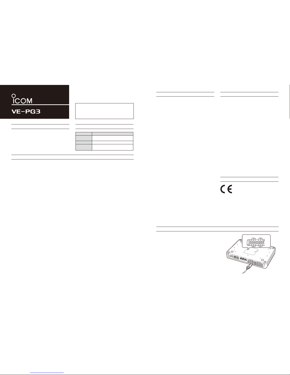
Before connecting cables, see the cable's manual and the
sticker on the bottom of the VE-PG3 for port information.
• Verify that both the VE-PG3 and connected devices are
turned OFF when connecting or disconnecting the cable.
• Hold the connector body when connecting or
disconnecting them.
• When other cables are connected, you can use needlenose pliers to carefully insert or remove connectors.
• Never bend or pinch the cable.
• Never place a heavy object on the cable.
• Never touch the cable with wet hands.
• Always connect the cable correctly. An incorrect connection
could damage the VE-PG3 and/or the transceiver.
VE-PG3 (bottom view)
Connection cable (optional)
Port information on the sticker
Sticker
A
B
RoIP GATEWAY
Page 2

1-1-32 Kamiminami, Hirano-ku, Osaka 547-0003, Japan
A-7046W-1EX Printed in Japan
© 2012 Icom Inc.
INITIALIZING THE VE-PG3
ABOUT THE FIRMWARE UPDATE FUNCTION
When [PWR/MSG] lights orange
Disconnect all cables from the VE-PG3, and then
connect the AC adapter.
• Verify that the [POWER] indicator lights green.
Push in and hold [INIT] on the bottom until all indicators
on the front panel light orange.
• When the initialization has been completed,
[PWR/MSG] and [V/RoIP] light green.
• After the initializing, reset the VE-PG3’s IP address,
operating mode, and so on.
The firmware may be updated when the functions and
specifications of the VE-PG3 are improved.
When a firmware update is available, the Firmware Update
function lights the [PWR/MSG] LED orange.
• To use the Firmware Update function, an internet connection,
DNS and default gateway settings are necessary.
See the VE-PG3 instruction manual for the setting details.
NOTE:
• NEVER turn OFF the power until the updating has been
completed. Otherwise, the VE-PG3 may be damaged.
• The Firmware Update function will not work under the
following conditions:
- While communicating with an IP telephone in the
converter mode.
- While an Emergency call is ongoing.
• Ask your dealer for updated function or specification
details.
*The indication may differ, depending on the setting.
*The indication may differ, depending on the setting.
:Black out
<Status>
[LED indication*]
[Operation]
:Light :Blink
Turn ON the power
[INIT]
Push in and hold
Bottom
Use a pin
Release
Rear
panel
AC
adapter
Lights
(Green)
Lights
(Green)
Lights
(Green)
Lights
(Orange)
Blinks
(Orange/Green)
Blinks
(Green)
Blinks
(Orange)
All LEDs light (Orange)
Use a pin.
Push in
and hold
Front
panel
Release
:Black out
<Status>
[LED indication*]
[Operation]
:Light :Blink
After the rebooting,
[PWR/MSG] lights green.
Lights
(Orange)
Blinks
(Green)
All LEDs light (Orange)
1
2
If you cannot access to the VE-PG3 setting screen, you can initialize the VE-PG3.
• Initializing clears all the settings.
• See the VE-PG3 instruction manual for initializing from the setting screen.
When [PWR/MSG] lights orange, a firmware update is ready.
Follow the procedures below to download and install the new
firmware.
Push in and hold [UPDATE] on the front panel until [PWR/MSG]
lights green.
• The VE-PG3 automatically starts to download and update
the firmware, and then reboots.
If the VE-PG3 is initialized after updating, reset the VE-PG3’s
IP address, operating mode, and so on.
See the VE-PG3 instruction manual for details.
The AMBE+2™ is a registered trademark of Digital Voice Systems, Inc.
Adobe and Reader are registered trademarks of Adobe Systems Incorporated in the United States and/or other countries.
Icom, Icom Inc. and the Icom logo are registered trademarks of Icom Incorporated (Japan) in Japan, the United States, the
United Kingdom, Germany, France, Spain, Russia and/or other countries.
All other products or brands are registered trademarks or trademarks of their respective holders.
ALL RIGHTS RESERVED. This document contains material protected under International and Domestic Copyright Laws and
Treaties. Any unauthorized reprint or use of this material is prohibited. No part of this document may be reproduced or transmitted in any form or by any means, electronic or mechanical, including photocopying, recording, or by any information storage and
retrieval system without express written permission from Icom Incorporated.
All stated specifications and design are subject to change without notice or obligation.
Page 3
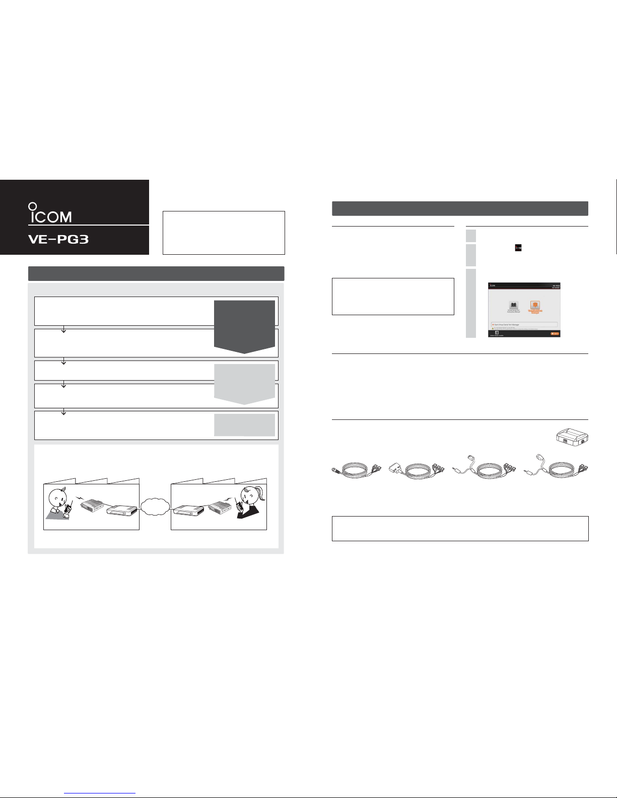
M AC adaptor ………… 1 M Cushion sheet …………………1
M Ferrite EMI filter …… 1 M Spare connectors ………… 24
M CD (UTILITY DISC)
Guides:
M Precaution leaflet M
Preparation leaflet (this guide)
M Installation 1 leaflet M Installation 2 leaflet
Step 1 Required items
Accessories About the CD (UTILITY DISC)
Options (As of December 2012)
Other items (As of December 2012)
M PC M LAN cable
M Ground cable M HUB*
2
M Icom transceiver*3 and their instruction manual.
M SIP phone (KX-UT123/KX-UT136 series (Manufacture: Panasonic))*
4
*2 The VE-PG3 can be directly connected to the PC using the MDI-X (crossover) type Ethernet cable.
*3 See the topic below regarding the connection cables.
*4 Necessary when you use the VE-PG3 in the Converter mode.
RoIP GATEWAY
PREPARATION
Thank you for purchasing the VE-PG3. The VE-PG3 is a
network converter that allows you to connect Icom radios
or repeaters to a VoIP network.
This guide describes the basic settings to operate the VEPG3.
READ ALL INSTRUCTIONS carefully and completely before using.
About the options
Approved Icom optional equipment is designed for optimal performance when used with an Icom product. Icom is not responsible for
the destruction or damage to an Icom product or the network device in the event the Icom product is used with equipment that is not
manufactured or approved by Icom.
OPC-2273 CONNECTION CABLE for the IC-M604 (Length: approximately 5m/16.4 ft)
OPC-2274 CONNECTION CABLE for the IC-FR5000/FR6000 (Length: approximately 5m/16.4 ft)
OPC-2275 CONNECTION CABLE for the IC-F5060/F6060 (Length: approximately 5m/16.4 ft)
OPC-2276 CONNECTION CABLE for the Icom microphone and speaker (Length: approximately 5m/16.4 ft)
CT-24*
5
DIGITAL VOICE CONVERTER to communicate using AMBE+2™ codec.
RC-FS10*6 REMOTE COMMUNICATOR to create a virtual radio or simple dispatcher on a PC.
*5 Necessary to communicate with an Icom repeater.
*6 Allows you to access and communicate with repeaters and transceivers on your IDAS IP Network.
CT-24
The preparation procedure
Following the procedure below, setup the VE-PG3.
Step 1
Required items
• Accessories
• The supplied CD (UTILITY DISC)
• Other items as listed to the right.
• Options
Step 2
Configure the transceiver
Step 3
Configure the network
Step 5
Connect the transceiver
Step 4
Configure the VE-PG3
Set the transceiver c hannel and volume level.
( See the trans ceiver's manual for th e setting de-
tails.)
Set the VE-PG3's IP address, according to your
system environment.
Connect the VE-PG3 a nd the transceiver, using the
appropriate optional cable.
• Verify that both the VE-PG3 and the transceiver
are turned OFF when connecting or disconnecting
the cable.
Select the operat ing mode and confi gure the VEPG3, according to your o perating needs.
CD (UTILITY DISC) contents
• Virtual Serial Port Manager*
1
• Virtual Serial Port Instruction Manual (PDF file)
• Adobe® Reader® Installer
*
1
Read the instruction manual for details, before attempting to
use.
[About the operating mode]
• Converter mode : When communicating between a SIP phone and the transceiver through the IP network, select this
mode.
• Bridge mode (default) : When communicating between 2 transceivers (A1 and B1 in the illustration below) through the IP
network, select this mode.
Factory A
VE-PG3
VE-PG3
Factory B
Transceiver B
Transceiver A
An example of the Bridge mode operation
(Radio to radio communication)
IP
Network
Transceiver “A1” (Extension)
Transceiver “B1” (Extension)
Preparation
(This guide)
Installation guide 1
(Separate leafl et)
Installation guide 2
(Separate leafl et)
(You can download the Instruction Manual from the Icom web site; http://www.icom.co.jp/world/)
Continued on the back side.Î
Insert the CD (UTILITY DISC) into a CD drive.
• You must log on as the administrator.
Double-click the icon (APPLICATION FILE) contained in the CD.
• Depend ing on the PC setting, t he Menu screen shown
below is automatically d isplayed.
1
2
The Menu screen as shown below appears.
• See the "Virtual S erial Port" PDF manual for details .
3
OPC-2273
OPC-2274 OPC-2275
OPC-2276
Read the “PRECAUTIONS” leafl et fi rst, if you have not done so.
Page 4

1-1-32 Kamiminami, Hirano-ku, Osaka 547-0003, Japan
A-7046W-2EX Printed in Japan
© 2012 Icom Inc.
Before connecting to the VE-PG3, set the transceiver and repeater as shown in the following table.
• The transceiver settings affect the audio quality.
• See the transceiver's instruction manual for the setting details.
• Turn OFF the Power Save function to prevent missing the beginning words of a call.
*Use the specified connection cable when connecting the transceiver or repeater to the VE-PG3.
The following transc eivers and repeaters can be used with t he VE-PG3.
• Marine transceiver : IC-M604
• Air band transceiver : IC-A110
• Mobile transceivers : IC-F5060 /IC-F6060 series
• Repeaters : IC-FR5000/IC-FR6000 series
When two or more transceivers are connected to the VE-PG3, the transmit signal from one transceiver can interfere with the other
transceivers.
Interference can be reduced by the methods shown below.
Step 2 Configure the transceiver or repeater
Transceiver and repeater settings
Usable transceivers and repeaters (As of December 2012)
To reduce interference
NOTE: Set the transceiver channel, volume level, TX output power, and other necessary settings, before
connecting to the VE-PG3.
NOTE: When two or more transceivers are connected to the VE-PG3, separate their antennas as far as possible to
reduce interference between them.
Model name IC-M604 IC-A110 IC-F5060/IC-F6060 series IC-FR5000/IC-FR6000 series
Channel any any any any
Audio volume level
Set the volume to
the 10 o'clock position.
Set the volume to
the 9 o'clock position.
any
Required optional cable* OPC-2273 OPC-2275 OPC-2275 OPC-2274
Use the antenna directivity
Even a non-directive antenna has less transmit emission in the
vertical direction. When installing two antennas, mount them at different heights to reduce interference.
Set the TX output power to Low
Setting the transmit power to low can reduce interference.
But, note that it also reduces the coverage area.
The AMBE+2™ is a trademark of Digital Voice Systems, Inc.
Set the channel (frequency) spacing to wide
There may be interference from an adjacent channel (frequency).
Setting the channel (frequency) spacing to wide can reduce interference.
Use a solid object as the shield screen
A solid object (such as a concrete wall which has a metal frame
inside, metal locker, and so on.) in between two antennas behaves
like a shield screen for the transmit signal, and can reduce interference.
Continued on the VE-PG3 INSTALLATION 11Î
Transceivers
Difference in height:
More than 1m; 3.3 ft
Antenna
VE-PG3
Behaves like a shield screen.
TransceiverTransceiver
Antenna
Antenna
VE-PG3
Page 5

(Continued on the back side.)Î
Step 3 Configure the network
Step 3 Configure the network (continued)
RoIP GATEWAY
INSTALLATION 1
Thank you for purchasing the VE-PG3. The VE-PG3 is a
network converter that allows you to connect Icom radios
or repeaters to a VoIP network.
This guide describes the basic settings to operate the VE-PG3.
READ ALL INSTRUCTIONS carefully and completely before using.
HUB
To the [DC] jack
To the [LAN] port
To the ground terminal
LAN cable**
(Purchase separately)
Ground wire
(Purchase
separately)
AC adaptor
(Supplied with the VE-PG3)
AC outlet
PC
(Example of the IP address;
192.168.0.100)
Ground
terminal
e
Connect the cables
Connect the power supply
r
Boot the PC
t
The [PWR/MSG] LED on the front
panel lights*.
*The indication may differ, depending on the setting. **Category 5 or higher.
Verify that the LEDs light
y
When the [LAN] LEDs on the rear don’t light, verify that the LAN
cable is securely connected.
Attach the cushions
q
Cushion Sheet
(Supplied with the VE-PG3)
Attach the ferrite EMI filter
w
q
w
LED indication:
q Lights: Full duplex
Doesn’t light: Half duplex
w Lights: Connected to the network
Blinks: While the line is communicating
Ferrite EMI filter
(Supplied with the VE-PG3)
Ferrite EMI filter
(Supplied with
the VE-PG3)
Wrap the cable once around
the ferrite EMI filter.
Power cable
R
WARNING!
To prevent electrical shock, television interference (TVI),
broadcast interference (BCI) and other problems, ground the
VE-PG3 through the ground terminal.
For best results, connect a heavy gauge wire or strap to a ground
terminal of an AC outlet or a long ground rod. Make the distance
between the ground terminal and ground as short as possible.
NEVER connect the ground terminal to a gas or electric pipe.
This may result in an electrical shock or cause a fire.
Setting the PC IP address
Set the static PC IP address (example: 192.168.0.100).
See the PC's instruction manual for the setting details.
Set the static VE-PG3 IP address assigned by the network
administrator.
Connect the devices to the VE-PG3 in order of q to y.
• Do not connect to the IP network before the confi guration is fi nished.
• A HUB which supports 100BASE-TX or better is recommended. Otherwise, an unexpected failure of communication may be caused.
• The VE-PG3 can be directly connected to the PC using a MDI-X (crossover) type Ethernet cable.
The following procedures (q to e) describe how to access the VE-PG3 setting screen using a web browser.
Following the procedure below, set the VE-PG3 IP address according to your network environment.
• Do not set the IP address to one that is already used for another network device.
1
2
3
q Open your web browser, then enter the IP address of
the VE-PG3 into the address bar.
*The default IP address is “ //192.168.0.1/.”
w Push the [ENTER] key.
• The Login Authentication screen will appear.
e Enter “admin” (fixed username) and “admin” (default
password) in their respective input fields on the Login
Authentication screen, and then click [OK].
q
Click the [Network] menu, and then click [IP Address].
w
Enter the VE-PG3 IP address, and then click <Apply>.
e
Click <Reboot> to reboot the VE-PG3.
r
After rebooting, enter “admin” (fixed username) and
“admin” (default password) in their respective input
fields on the Login Authentication screen, and then
click [OK].
To prevent unauthorized access
You must be careful when choosing your password, and
change it occasionally.
See the VE-PG3 instruction manual for the password setting.
• Choose one that is not easy to guess.
• Use numbers, characters and letters (both lower and upper case).
About web browsers
Only Microsoft Internet Explorer 9 or later must be used
with the VE-PG3.
Activate the JavaScript and set to allow Cookies on your
web browser to correctly display the setting screen.
If other browsers are used, the screen may not be correctly
displayed.
Menu Item Setting Screen Setting Item Item Name Value
Network IP Address IP Address IP Address 192.168.0.1
Subnet Mask 255.255.255.0
DHCP Server DHCP Server DHCP Server Disable
Router WAN Connection Type Connection Type No Connection
Operating Mode Operating Mode Operating Mode Operating Mode Bridge
EXT I/O Port Mode
Connection Unit
EXT I/O Unit
EXT I/O Port Mode Separate
Port Settings
Transceiver 1 (TRX1)/Transceiver 2 (TRX2)
Transceiver Model Transceiver Model IC-F5060/F6060
Management Administrator Administrator Username admin (fi xed)
Current Password: admin (lower case)
Firmware Update Automatic Update Automatic Update Enable
Network and System default settings
About the IP address
If the network part of the PC IP address is different from
that of the VE-PG3, you cannot access the VE-PG3
setting screen.
If the following message is displayed on the screen after
the rebooting, change the PC IP address according to
your network environment, and then click [Back].
Continued from the separate leaflet “PREPARATION.”
192.168.0.1/
Enter
Read the “PRECAUTIONS” leafl et fi rst, if you have not done so.
q Click
w Click
R
WARNING!
NEVER use other than the specified AC adapter. This may result
in an electrical shock, cause a fire or damage the VE-PG3.
q Enter
w Click
q Enter
w Click
q Configure
w Click
Page 6

1-1-32 Kamiminami, Hirano-ku, Osaka 547-0003, Japan
A-7046W-3EX Printed in Japan
© 2012 Icom Inc.
Continued on the "INSTALLATION 2" leaflet.Î
Step 4 Configure the VE-PG3
q Click the [Operating Mode] menu.
• The [Operating Mode] screen appears.
w Verify that [Bridge] is selected.
e
Select [Unicast] for the port (example: Transceiver 1 (TRX1)).
• When using in the Multicast mode, you can skip this step.
r Click <Apply>.
• When you are asked to reboot the VE-PG3, follow the instructions.
t After rebooting, click the [Port Settings] menu, then
[Transceiver 1 (TRX1)].
• The [Transceiver 1 (TRX1)] screen appears.
y Verify that the radio to be connected to the port (example:
IC-F5060/F6060) is selected.
u Click the [Bridge Connection] menu, then [Bridge
Connection].
• The [Bridge Connection] screen appears.
i Enter the IP address of the VE-PG3 in area B (example
:192.168.0.3).
o Click <Apply>.
!0 Click <Connect>.
• Verify that “During transmit” appears.
!1 Confi gure the VE-PG3 in area B, by following the same
procedure.
q Click the [Network] menu, then [DHCP Server].
• The [DHCP Server] screen appears.
w Select “Enable,” and then click <Apply>.
e Click the [Operating Mode] menu.
• The [Operating Mode] screen appears.
r Select [Converter].
t Click <Apply>.
• When you are asked to reboot the VE-PG3, follow the instructions.
y After rebooting, click the [Port Settings] menu, then
[Transceiver 1 (TRX1)].
• The [Transceiver 1 (TRX1)] screen appears.
u Verify that the radio to be connected to the port (example:
IC-F5060/F6060) is selected.
i Click the [Extension Connect] menu, then [Extension
Connect].
• The [Extension Connect] screen appears.
o Enter radio A's extension number, default call destination
number and so on, and then click <Apply>.
• The radio A's call setting is added on [List of Extension Entries].
!0 Enter IP Telephone's extension number, default call destination
number, MAC address and so on, and then click <Apply>.
• The IP Telephone's call setting is added on [List of Extension
Entries].
!1 Initialize the IP telephone (“Factory Setting”).
Select the Converter mode or the Bridge mode, and then confi gure the ports according to your operating needs.
• The following is an example of connecting the radio to [TRX1] (upper slot) on the VE-PG3.
• When the operating mode or setting of the port (to connect the radio) has been changed, the related settings are retur ned to their default.
• See the VE-PG3 instruction manual for details.
When using in the Bridge mode
When using in the Converter mode
Area A Area B
VE-PG3
(192.168.0.2)
[TRX1]
[TRX1]
VE-PG3
(192.168.0.3)
Radio A
Radio B
An example of communication in the Bridge’s unicast mode.
(Radio to radio communication)
IP
Network
Radio A1(Extension) Radio B1(Extension)
Area A
Area B
VE-PG3
(192.168.0.2)
[TRX1]
SIP phone
(KX-UT123/KX-UT136 series)
Radio A
An example of communication in the Converter mode.
(Radio to IP telephone communication)
IP
Network
[LAN]
Extension number
401
HUB
Extension number
301
Radio A1(Extension)
Verify
q Click
w Verify
Select
Verify that the port to connect the radio is selected.
Enter
Select
Click
Click
Click
Verify
Verify
Click
Select
Added
Added
q Configure
w Click
w Click
q Configure
Page 7

Continued on the back side.Î
Step 5 Connect the transceiver (continued)
RoIP GATEWAY
INSTALLATION 2
VE-PG3 (Rear view)
Icom’s transceiver
(IC-F5060/IC-F6060 series)
(Rear view)
(Front view)
To the external speaker jack
To the microphone connector
LINE2
LINE1
PHONE
• This is an example to connect the transceiver to [TRX1] on the VE-PG3.
ABC
Be sure to insert the
connectors top side up.
Bottom
Top
A
1234
OPC-2275
AABC
To [TRX1] (Upper slots)
Step 5 Connect the transceiver
NOTE:
• Verify that both the radio and the VE-PG3 are turned OFF when connecting or disconnecting the transceiver.
• Keep the radio away from a PC, AC adaptor and other electronic equipment. The noise emitted from those equipment may interfere
with the radio.
• When operating the radio, do not transmit near the IP telephone.
• If the voice level is too low, the VE-PG3 cannot detect the voice input, and the communication route will not be connected.
Set the threshold level to lower, or set the Automatic Disconnect Timer to "0" (disabled).
(See the VE-PG3's instruction manual for setting details.)
Set the transceiver channel, TX output power, and other necessary settings.
(See the transceiver's instruction manual and the “PREPARATION” leaflet for setting details.)
1
Turn OFF both the transceiver and the VE-PG3, and then connect the transceiver, as shown below.
2
Turn ON the VE-PG3 and the transceiver.
3
When using in the Bridge mode
When using in the Converter mode
[The procedure to call the IP telephone from transceiver A1.]
q
Area A
Radio A1's operator: While holding down [PTT], say
something (example: “Test, Test, Test”) into the microphone at a normal voice level.
• The IP telephone in the area B detects the voice, and starts to
ring.
w
Area A/B
Radio A1's operator: Release [PTT] to receive.
Person on the IP telephone: While the IP telephone is
ringing, take the handset off the hook, and then speak
into the telephone at a normal voice level.
e
Area A/B
Radio A1's operator: When the person on the IP tele-
phone is finished speaking, hold down [PTT] and speak
into the microphone.
[The procedure to call transceiver A1 from the IP telephone.]
q
Area B
Person on the IP telephone: Take the handset off the
hook, dial “301,” and then speak into the telephone at a
normal voice level.
• The communication route is connected to radio A whose extension number is “301,” and then radio A transmits the audio
to radio A1.
w
Area A/B
Radio A1's operator: When the person on the IP tele-
phone is finished speaking, hold down [PTT], and speak
into the microphone at a normal voice level.
Release [PTT] to receive.
Person on the IP telephone: When radio A1's operator
is finished speaking, you can start to speak again.
• Speak only when radio A1's operator stops speaking.
Area A
Area B
VE-PG3
(192.168.0.2)
[TRX1]
[TRX1]
VE-PG3
(192.168.0.3)
Radio A
Radio A1
(Extension)
Radio B1
(Extension)
Radio B
IP
Network
All transceivers in each area must be set to the same settings.
Area A
Area B
VE-PG3
(192.168.0.2)
[TRX1]
Radio A
Radio A1
(Extension)
IP
Network
Extension No.
301
Extension number
401
HUB
All radios in the area must be set to the same settings.
[LAN]
IP telephone
(KX-UT Series)
NOTE:
• Full duplex communication is impossible.
Communicate with each other by taking turns speaking.
• Pause briefly before you speak, to confirm your party has finished speaking.
• The communication route will be disconnected when the IP telephone's handset is put on the hook, or the VE-PG3 receives no
audio for the preset time (default: 15 seconds).
Continued from the separate leaflet “INSTALLATION 1.”
Thank you for purchasing the VE-PG3. The VE-PG3 is a
network converter that allows you to connect Icom radios
or repeaters to a VoIP network.
This guide describes the basic settings to operate the VE-PG3.
READ ALL INSTRUCTIONS carefully and completely before using.
• Radio A1 and B1 can normally communicate as if they are directly communicating in the simplex mode.
Read the “PRECAUTIONS” leafl et fi rst, if you have not done so.
Page 8

1-1-32 Kamiminami, Hirano-ku, Osaka 547-0003, Japan
A-7046W-4EX Printed in Japan
© 2012 Icom Inc.
(You can download the Instruction Manual from the Icom web site; http://www.icom.co.jp/world/.)
For your information
The setting data or firmware can be automatically loaded
into the VE-PG3 from a USB memory.
It is useful to recover the configuration or to update the
firmware.
• The USB memory is not supplied. Purchase separately.
• See the VE-PG3 instruction manual for details.
About the USB memory
• A USB memory such as one with biometric authentication, or
one with password protection is not supported.
• Turn OFF the VE-PG3's power before inserting or removing
the USB memory, to prevent data corruption.
• Either one of the USB slots accepts the USB memory, but
insert only one USB memory at a time.
• Inser the USB memory securely.
• NEVER remove the USB memory or turn OFF the VE-PG3's
power, while transferring data. It will cause data corruption,
or damage the USB memory.
• After the firmware updating is finished, check the firmware
version on the setting screen to verify that the update was
correctly done.
• When importing setting data from the USB memory to
the VE-PG3, the originally programmed setting data is
automatically saved as “bakdata.sav” in the USB memory, as
a backup.
Turn OFF the VE-PG3’s power,
and then insert the USB memory securely.
Then, turn ON the power again.
Automatic setting data load with a USB memory
About the LED indication (See the "PRECAUTIONS" leafl et about the <INIT> and <UPDATE> buttons.)
Front view
<UPDATE> button [WAN] LED [EXT] (1/2) LED
[PWR/MSG] LED
[V/RolP] LED
[D-TRX] LED
[TRX] (1/2) LED [USB] port
(USB2.0)
About the setting screen
• See the VE-PG3 instruction manual for details.
e Setting screen
Displays the settings and values when you click the screen
name.
r Setting buttons
Save or cancel setting values.
If “Items that need to be restarted have changed.” is displayed on the screen when you click the [Apply] button, click
the [OK] button.
The VE-PG3 reboots, and the setting items and values are
updated.
The following message is displayed on the screen while the
VE-PG3 is rebooting.
• If the setting screen does not automatically return, click [Back]
about 30 seconds after the “Now rebooting.” message appears.
• Items and buttons may differ, depending on the setting.
q Link to the Icom web site
Click the Icom logo to open the Icom web site if your PC is
connected to the Internet.
w Setting menu
Displays the screen name list on a menu line. When you
click each menu title, a list of items drops down which you
can use to select the desire setting item.
LED Indication In the Converter mode
In the Bridge mode
PWR/MSG Doesn't light Power is OFF
Green Lights Power is ON
Blinks Booting
Red Lights –
Blinks –
Orange Lights A firmware update is ready./Downloading new firmware.
Blinks Accessing the USB memory.
(While loading the setting file or updating the firmware.)
Booting
Initialization is in progress. (Green and Orange LEDs alternately light.)
Firmware update is in progress.
WAN Doesn't light No network connection./Connecting to the network is in progress.
Green Lights Connected to the WAN line. (An IP address has been obtained.)
Blinks The WAN line is communicating.
Red Lights –
Blinks
Authentication error/failed (PPPoE)
Failed to obtain IP address (DHCP) (Time-out timer: 30 seconds)
Orange Lights –
Blinks –
V/RoIP Doesn't light
No registration
Not connected
Green
Lights Registration succeed (All entries)
Connected
Blinks The line is communicating.
Red Lights –
Blinks 1 or more registrations failed.
Orange Lights –
Blinks –
D-TRX* Doesn't light No transceiver is connected, or it is turned OFF.
Green Lights Receiving an audio signal.
Blinks –
Red Lights Sending an audio signal.
Blinks –
Orange Lights The transceiver is communicating.
Blinks –
TRX1
TRX2
Doesn't light No transceiver is connected, or it is turned OFF.
Green Lights Receiving an audio signal.
Blinks –
Red Lights Sending an audio signal.
Blinks –
Orange Lights The transceiver is communicating.
Blinks –
EXT1
EXT2
Doesn't light No input or output signal.
Green Lights Input is busy.
Blinks –
Red Lights Output is busy.
Blinks –
Orange Lights Input or output is busy.
Blinks –
*For the operation using an IC-FR5000/FR6000.
• All indicators light while updating the fi rmware or rebooting.
• The indication may differ, depending on the setting.
q
w
r
e
Page 9

INSTRUCTION
Virtual Serial Port
Thank you for purchasing VE-PG3.
The Virtual Serial Port function of VE-PG3 allows you
to control a
device with a serial communication interface,
through the
TCP/IP network.
READ ALL INSTRUCTIONS carefully and completely before using.
1. System requirements (As of November 2012)
3. Adding the Virtual Serial Port
Operating System
• Microsoft® Windows® 8 (32/64 bit)
• Microsoft
®
Windows® 7 (32/64 bit: Service Pack1 or later)
• Microsoft
®
Windows Vista® (32/64 bit: Service Pack2 or later)
• Microsoft
®
Windows® XP (32 bit: Service Pack3 or later 64 bit: Service Pack2 or later)
NOTE:
Microsoft® Windows® RT is not supported.
Because the system requirements may differ, depending on your PC environment, the operation is not guaranteed.
“Windows 7” is used for the descriptions in this instruction guide.
Connection
The Virtual Serial Port function of the VE-PG3 is designed to remotely control a device with a serial communication interface.
Connect the VE-PG3 and the serial device using the modifi ed RS-232C cable, as illustrated below.
• Verify that both the VE-PG3 an d device are turned OFF when connec ting or disconnecting the c able.
Example: Connecting an RS-232C cable with the 9-pin D-sub connector.
Insert the CD (UTILITY DISC) into a CD drive.
• You must log on as the administrator.
1
Double-click the icon (APPLICATION FILE) contained in the CD.
2
Click [Virtual Serial Port Manager] on the menu
screen.
3
If “User Account Control” appears, click [Yes] to continue.
4
5
When the installation is fi nished, the COM port number
(Example: COM10) will appear in the above window.
• The COM port numb er may differ, depending on your PC
environment.
6
Click
To the serial communication device
LINE2
LINE1
PHONE
BC
BC
[EXT1] port (lower slot)
VE-PG3 (rear view)
VE-PG3 (rear view)
VE-PG3 (rear view)
B
C
Connectors
(Top side)
C1
WIRING
C2 C3 C4B4
GND TXD RXD RTSCTS
123 4123 4
RS-232C
(9-pin D-sub connector)
tqwer
oyui
Top
Top
Top Bottom
Bottom
Bottom
1234
1234 1234
1234 1234
tqwer
oyui
tqwer
oyui
NOTE: A data transmission delay may occur a s the data routes through the network.
The error caused by the de lay may be improved if the time out timer is set to a long value.
2. Preparation on the VE-PG3
• This is an example to con nect the serial device to [EX T1] (lower slot) on the VE-PG3.
[EXT1]
[LAN]
VE-PG3
Serial
communication
device
LAN cable
(Purchase separately)
Connection cable
PC
(
Example: 192.168.0.100
)
192.168.0.1
(IP address on
the local area network)
Access the VE-PG3 setting screen.
• See the VE-PG3 instruction manual for details.
1
Click <Apply>.
4
Read the message, and then click <OK>.
5
Click the [Port Settings] menu, and then click
[EXT Output 1 (EXT1)].
2
Select “Enable.”
• The [Serial Communication] items will appear.
4
3
Click
• This is an exa mple connecting the devic e
to [EXT1] (lower slot) on th e VE-PG3.
• Use the spare connectors* which are
supplied with the VE-PG3.
*Manufacturer: DDK.
Name: 232D-04S1B-DA5-FA
When the Virtual Serial Port window appears, click
[Add].
• If a security warning dialog appears or the application asks
you to reboot the PC, follow the instructions.
(Up to 64 virtual serial ports can be added.)
Confi gure the [Serial Communication] items as shown
below.
(The screen may dif fer, depending on the setting.)
Select
Configure
The same TCP port n umber here must be set
as the Virtual Ser ial Port number.
(See the back side fo r details.)
Click
Click
Page 10

1-1-32 Kamiminami, Hirano-ku, Osaka 547-0003, Japan
A-7046-5EX © 2012 Icom Inc.
Icom, Icom Inc. and the Icom logo are registered trademarks of Icom Incorporated (Japan) in Japan, the United States, the
United Kingdom, Germany, France, Spain, Russia and/or other countries.
Adobe and Reader are registered trademarks of Adobe Systems Incorporated in the United States and/or other countries.
Microsoft, Windows and Windows Vista are registered trademarks of Microsoft
Corporation in the United States and/or other countries.
All other products or brands are registered trademarks or trademarks of their respective holders.
ALL RIGHTS RESERVED. This document contains material protected under International and Domestic Copyright Laws and
Treaties. Any unauthorized reprint or use of this material is prohibited. No part of this document may be reproduced or transmitted in any form or by any means, electronic or mechanical, including photocopying, recording, or by any information storage and
retrieval system without express written permission from Icom Incorporated.
All stated specifi cations and design are subject to change without notice or obligation.
4. Configuring the Virtual Serial Port
If “User Account Control” appears, click [Yes] to continue.
4
If “User Account Control” appears, click [Yes] to continue.
4
When the Virtual Serial Port window appears, double-
click on the port to confi gure (Example: COM10).
5
The property window will appear.
Select the [Port Settings] tab in the property window,
and enter the VE-PG3's IP address (on the LAN)
(See the top side for details).
6
Enter the TCP port number (See the top side for details), and then click <OK>.
7
5. Deleting the Virtual Serial Port
When the Virtual Serial Port window appears, select
the port to delete (Example: COM10), and then click
[Delete].
5
Confi rm the port setting, and then click <Close>.
8
• To simultaneously delete multiple ports, select them while
holding down [S hift] or [Ctrl].
• If the application asks you to reboot the PC, follow the instructions.
Insert the CD (UTILITY DISC) into a CD drive.
• You must log on as the administrator.
1
Insert the CD (UTILITY DISC) into a CD drive.
• You must log on as the administrator.
1
Double-click the icon (APPLICATION FILE) in the
window.
2
Double-click the icon (APPLICATION FILE) contained in the CD.
2
Click [Virtual Serial Port Manager] on the menu
screen.
3
Click [Virtual Serial Port Manager] on the menu
screen.
3
[For your information]
• You can open the property window in the Device Manager.
• [Address] on the [Port Settings] tab (In step 6) can also accept a domain name of up to 255 characters.
• Right-click on the title bar of the Virtual Serial Port window,
and then select [About(A)...] to open the [Version info] window, as shown below.
•
“Virtual Serial Port Ver. 1.03.” is used for the descriptions in this
instruction guide
.
Double-click
(This screen is an example.)
Double-click
q Enter
w Click
w Enter
q Select
Uncheck this item, or the data will not be encrypted.
Uncheck this item, or the data will not be encrypted.
Click
Click
If necessary, confi gure the serial port settings.
Modifying the se settings affects only the V irtual Serial Port functi on.
w Click
q Confirm
q Select
w Click
 Loading...