

Page 1
OPC-2073
Connection cable (For the transceiver)
OPC-2074
Connection cable (For the repeater)
q
w
r
t
y
e e
If the channel for transceiver
A2 and transceiver A3 is set
to CH2, transceivers in Area
A can communicate with
transceivers in Area B.
If the channel for transceiver
B1 and transceiver B2 is set
to CH18, transceivers in
Area B can communicate
with transceivers in Area A.
[Area A]
Specified Icom transceiver
Channel: CH2
Channel: CH18
Transceiver A1 Transceiver A2 Transceiver A3
[Area B]
Specified Icom transceiver
Transceiver B1 Transceiver B2 Transceiver B3
IP
network
VE-PG2
192.168.0.2
VE-PG2
192.168.0.3
[LAN] [LAN]
OPC-2073
OPC-2073
Transmission from transceiver A1 to transceiver B3.
Transmission from transceiver B3 to transceiver A1.
Example of the Bridge mode operation
[TRX1]
[TRX1]
Channel: CH2
Transceiver A
Channel: CH18
Transceiver B
Transmits to all transceivers in the network
Example of the Multicast mode operation
IP
network
Transmits to all transceivers in the network
Example of the Multicast mode operation
Transmits to the specified transceiver in the network
Example of the Unicast mode operation
IP
network
IP
network
3. Operation mode
Example of the Selective call mode opration
Then starts communicating through the VE-PG2 A and VE-PG2 B.
VE-PG2 A transmits calling signal to the VE-PG2 B when DTMF code (example: “1”) is received.
w
e
(Transceiver A)
(VE-PG2 A)
(VE-PG2 B)
(Transceiver B)
q
Transmits a DTMF code (example: “1”) to communicate with Transceiver B through the IP network.
VE-PG2 finishes communicating when no audio is sent to transceivers A and B for 15 seconds.
Or, hold down transceiver’s [PTT] and [#] for 1 second to transmit a # DTMF signal from transceivers A or B.
IP
network
Installation guide q
RoIP GATEWAY
VE-PG2
This guide describes about the preparation, operation
mode, connection, setting screen and IP address setting.
Read ““PRECAUTIONS” first if you have not read it. first if you have not read it.
Step1: Installation guide q Step2: Installation guide w
1. Preparation
Accessories
• AC adapter
This installation guide describes the VE-PG2 operating
mode (Bridge mode and Selective call mode), and the
sample connection settings.
Read “Installation guide“Installation guideInstallation guide w” for the sample connection for the sample connection
setting details.
Download the VE-PG2 instruction manual from Icom web
site (http://www.icom.co.jp/world/), if necessary.
Options
Required items
To set the VE-PG2, the following hardware and software are
required:
• PC (PC connected by an Ethernet cable)
Microsoft® Windows® XP, Microsoft® Windows Vista® or
Microsoft® Windows® 7 is installed.
• Ethernet cable • Connection cable
• Ground wire (OPC-2073 or OPC-2074)
• Hub • Specified Icom transceiver
(100BASE-TX or faster products)
[Connecting a PC using an Ethernet cable]
Use an Ether net crossover cable when connecting the
VE-PG2 to a PC, because the VE-PG2 does not have the
Ethernet straight/crossover cable automatic detect function.
Also, be careful of the cable polarity when connecting the
VE-PG2 to a HUB that does not have the Ethernet straight/
crossover cable automatic detect function. If the polarity is
wrong, the [LAN] LED will not light.
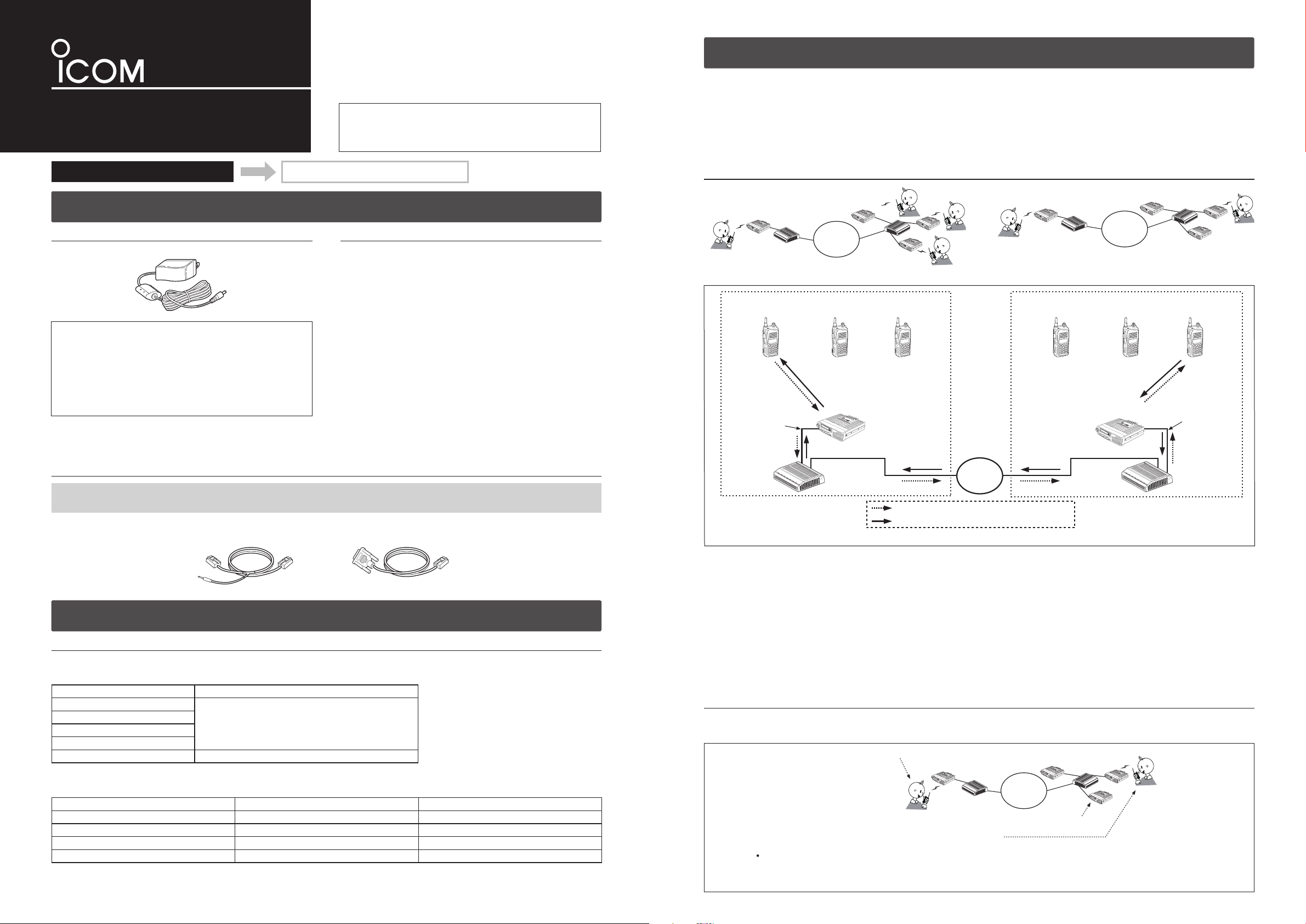
The VE-PG2 has two operating modes, “Bridge mode (default)” and “Selective call mode.”“Bridge mode (default)” and “Selective call mode.”Bridge mode (default)” and “Selective call mode.”” and “Selective call mode.” and “Selective call mode.”“Selective call mode.”Selective call mode.””
• The transceiver connected to the VE-PG2 and transceiver to be called must be set to the same channel.
The VE-PG2s can be transmitted signals to the transceivers through the IP network.
In the Bridge mode has “Multicast mode” and “Unicast mode” operations.“Multicast mode” and “Unicast mode” operations.Multicast mode” and “Unicast mode” operations.” and “Unicast mode” operations. and “Unicast mode” operations.“Unicast mode” operations.Unicast mode” operations.” operations. operations.
• In the Multicast mode, the VE-PG2 calls all transceivers that are connected to the VE-PG2 (default).
• In the Unicast mode, the VE-PG2 calls a specified transceiver that is connected to the VE-PG2.
Bridge mode operation
(The transceiver's instruction
manual)
CAUTION: Use only the specified cable to connect a transceiver or repeater to the VE-PG2. Using another cable, like an
Ethernet cable may damage the VE-PG2, transceivers or repeaters.
2. Transceiver and repeater settings
Usable transceivers and repeaters
The following transceivers and repeaters are usable with the VE-PG2.
The optional connection cable is required, refer to the following table.
Model name Optional connection cable
IC-F121S/IC-F221S
IC-F121/IC-F221
IC-F111S/IC-F211S
IC-F111/IC-F211
IC-FR5000/IC-FR6000 OPC-2074 (approximately 5 m; 16.4 ft)
Set the transceiver and repeater as shown in the following table before connecting to the VE-PG2.
Setting items Transceiver Repeater
Channel any any
Audio volume level Set the volume to the 12 o’clock position any
External I/O (D-sub 25) port setting*
Required optional connection cable*
*1The CS-FR5000 cloning software and OPC-1122U cloning cable are required when you set External I/O D-sub 25 port setting.
*2Use the specified connection cable when connecting the transceiver or repeater to the VE-PG2.
OPC-2073 (approximately 5 m; 16.4 ft)
1
2
– Ext. I/O 18 Output Low Voltage 2
OPC-2073 OPC-2074
Example of the Bridge mode operation: Calling a transceiver in another area (Transceiver A1 calls Transceiver B3).
q Set Transceiver A1’s channel to CH2, and while holding down [PTT], speak into the microphone at your normal voice level
to call Transceiver B3.
w When Transceiver A receives the AF signal from Transceiver A1, Transceiver A sends the AF signal to the VE-PG2 through
the OPC-2073.
e The VE-PG2 ([Area A]) converts the AF signal to an RoIP signal, then transmits it from the [LAN] port to the VE-PG2 ([Area
B]) through the IP network.
r The VE-PG2 ([Area B]) converts the RoIP signal to an AF signal, then Transceiver B receives the signal.
t Transceiver B3 receives the signal from Transceiver B.
y Transceiver B3 can also transmit a signal to communicate with Transceiver A1.
Selective call mode operation
The DTMF tone code can be used for calling the specified station or controlling the external equipment in the Selective call
mode.
Page 2
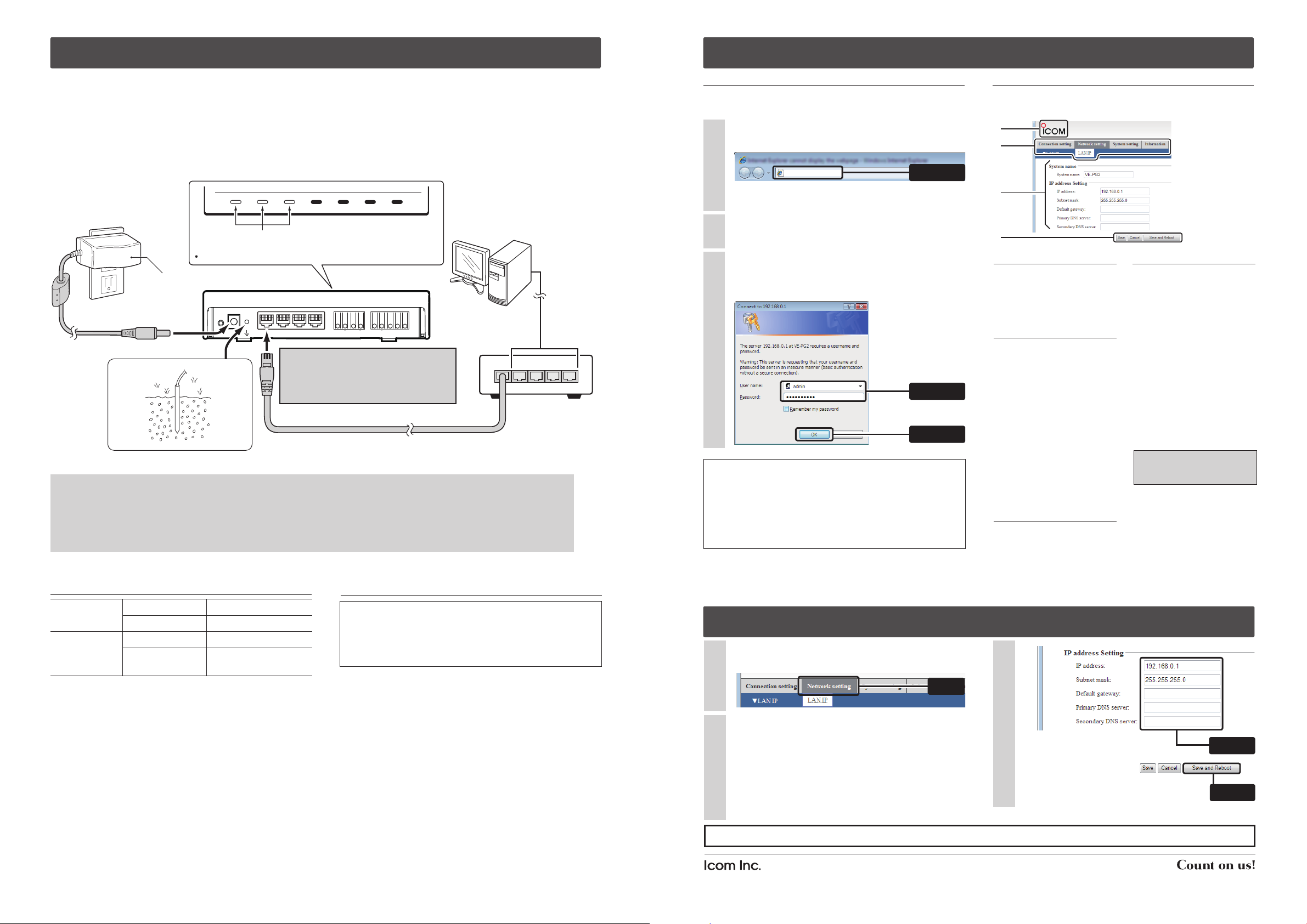
4. Connection
MODE DC LAN TRX1 TRX2 TRX3 IN
+ + +
OUT SW ABC
Connect the Ethernet cable
Start up the PC
Connect the AC adapter
to an AC outlet
Make sure the LEDs are lit.
To any unused
HUB port
HUB
To the VE-PG2 [LAN] port
To the DC jack
Supplied AC adapter
VE-PG2
A Ethernet cable (purchase separately)
PC IP address
(example: 192.168.0.100)
1 2 3 4 5
q
e
After turning the power ON, make sure [POWER], [LAN]
and [VoIP] are lit.
The LEDs light as a default or after resetting the VE-PG2.
w
r
POWER VoIP TRX1 TRX2 TRX3LAN EXT
CAUTION:
Connect the Ethernet cable to ONLY the
[LAN] port. If it is connected to [TRX1],
[TRX2] or [TRX3] port, the VE-PG2 and
HUB may be damaged.
GROUND
5. Accessing the VE-PG2 setting screen
Connect the Ethernet cable, HUB, the ground cable and AC adapter to the VE-PG2 by following steps q to r as shown
below.
(Connect the AC adapter with the VE-PG2 after connecting the Ethernet cable.)
• Disconnect the HUB from the established network before connecting the Ethernet cable, only if the VE-PG2 is in the default
mode.
• The VE-PG2 can be connected directly to the PC using the MDI-X (crossover) type Ethernet cable.
R WARNING!
To prevent electrical shock, television interference (TVI), broadcast interference (BCI) and other problems, ground the
VE-PG2 through the ground terminal.
For best results, connect a heavy gauge wire or strap to a ground terminal of an AC outlet or a long ground rod. Make
the distance between the ground terminal and ground as short as possible.
NEVER connect the ground terminal to a gas or electric pipe. This may result in an electrical shock or cause a fire.
Network and System default settings
Setting the PC IP address
Accessing the VE-PG2 setting screen
The following proced ure descr ibes how t o acce ss the
VE-PG2 setting screen from a web browser on the PC.
Open a web browser, and then enter the VE-PG2 IP
1
address in the address bar.
http://192.168.0.1/
Enter
The factory default IP address setting is shown as an
example.
Push [Enter]. The login authentication window will
2
open.
Enter “admin” (default user name) and “wavemaster”
3
(default password) in their respective input field, and
then click [OK] to display the VE-PG2 setting screen.
q Enter
w Click
About web browsers
Only Microsoft Internet Explorer 8 or later should be used
with the VE-PG2.
Activate the JavaScript and set to allow Cookies on your
web browser to display the setting screen correctly.
If ot her bro wsers are used , the scre e n may no t be
displayed correctly.
Setting screen descriptions
See the instruction manual (PDF file: Download from the
Icom web site) for details of the setting screen.
q
w
e
r
q Link to Icom web site
Click the Icom logo to link to
the Icom web site if your PC
is connected to the Internet.
r Setting buttons
S a v e o r ca n ce l s et t in g
values.
If “The setting which should“The setting which should
be rebooted was changed.”
w Selects the setting
screen
Displays the screen name
list on a menu line. When
y o u p l a c e t h e m o us e
pointer on each menu title,
a list of items drops down
which you can use to select
the desire setting.
( Example: Place the mouse
pointer on “Connection set-“Connection set-Connection setting”, and then click “Oper-”, and then click “Oper-, and then click “Oper-“Oper-Operating mode” shown on the” shown on the
list.).)
e Setting items and
value display
Dis p lays th e s e tting an d
values when you click the
scr e e n na m e (ex a m p le :
is displayed on the screen
when you click the [Save]
button, click the [Save and
Reboot] button.
The VE-PG2 reboots, and
the setting items and values
are updated.
The following message is
disp l ayed on t h e s c r e e n
while the VE-PG2 is rebooting.
VE-PG2 is rebooting.
Click [Back] after VE-PG2 has rebooted.
• T he setting screen does
not automatically return,
s o cl i c k [B ac k ] ab o u t
3 0 s e c o n d s af te r th e
“VE - P G2 is r e b ooti n g ”VE- P G 2 is re b o o ting ””
message appears.
Clicking “Operating mode”“Operating mode”Operating mode””
displays the setting screen).
Network setting
System setting
To set the VE-PG2 to the default setting, see “Precautions”“Precautions”Precautions””
for details.
*User settable.
Microsoft, Windows and Windows Vista are registered trademarks of Microsoft Corporation in the United States and/or other countries.
All other products or brands are registered trademarks or trademarks of their respective holders.
This product includes in GoAhead WebServer software of GoAhead Software Inc.
© 2002 GoAhead Software, Inc. All Rights Reserved.
IP address 192.168.0.1*
Subnet mask 255.255.255.0*
Administrator ID admin (Fixed)
Administrator
password
wavemaster*
Set the static PC IP address (example: 192.168.0.100)
See the instruction manual which comes with the PC for
details on setting the PC IP address.
When you set the static VE-PG2 IP address, assign the IP
address by network administrator.
6. VE-PG2 IP address setting
Click “LAN IP” in the “Network setting” to display the“LAN IP” in the “Network setting” to display theLAN IP” in the “Network setting” to display the” in the “Network setting” to display the in the “Network setting” to display the“Network setting” to display theNetwork setting” to display the” to display the to display the
1
2
“LAN IP” setting screen.LAN IP” setting screen.” setting screen. setting screen.
Select
Set the IP address and subnet mask of the VE-PG2.
2
Be sure not to input the same IP address as another
device’s address.
q Enter
When you update the firmware online, connect the
VE-PG2 to the Internet and set the default gateway
and DNS server addresses as the addresses used
in the network.
w Click
When finished, click [Save and Reboot].
+See “Installation guide w” for bridge and selective call mode setting examples.
1-1-32 Kamiminami, Hirano-ku, Osaka 547-0003, Japan
A-6838W-2US Printed in Japan
© 2010 Icom Inc.
Page 3

MODE DC LAN TRX1 TRX2 TRX3 IN
+ + +
OUT SW ABC
1 2 3 4 5
MODE DC LAN TRX1 TRX2 TRX3 IN
+ + +
OUT SW ABC
q
w
t
y
e
To the [LAN] por t
To the [TRX1] por t
HUB
(192.168.0.2)
The [TRX1] port number: 21500
Connect the transceiver’s microphone connector and speaker jack.
NOTE: When using the repeater, connect the optional OPC-2074 to the repeater’s ACC connector.
Repeater’s rear panel
OPC-2074
ACC connector
[Area A]
[Area B]
Transceiver B
channel 2
Connect an Ethernet cable
Connect an Ethernet cable
VE-PG2
To the [TRX1] por t
(192.168.0.3)
The [TRX1] port number: 21500
VE-PG2
To the [LAN] por t
Connect the transceiver’s microphone connector and speaker jack.
Transceiver A
channel 2
Transceiver C
channel 10
Transceiver D
channel 10
NOTE: First, connect the transceiver
to the VE-PG2 using the optional
OPC-2073. Then turn ON the power
to the transceiver and the VE-PG2.
NOTE: First, connect the transceiver
to the VE-PG2 using the optional
OPC-2073. Then turn ON the power
to the transceiver and the VE-PG2.
Connect to the transceiver A’s speaker jack.
Connect to the transceiver C’s speaker jack.
CAUTION:
To connect the transceivers or repeaters, use only the following cables:
OPC-2073 (For the transceivers) or OPC-2074 (For the repeaters).
Connect the specified cables to [TRX1], [TRX2] or [TRX3] only.
Using another cable, like an Ethernet cable may damage the VE-PG2,
transceivers or repeaters.
MODE DC LAN TRX1 TRX2 TRX3 IN
+ + +
OUT SW ABC
Connect the optional OPC-2074 to
[TRX1], [TRX2] or [TRX3] only.
GROUND
GROUND
Turn the transceivers’ power ON,
and then set the transceiver A
volume to the 12 o’clock position.
Turn the transceivers’ power ON,
and then set the transceiver C
volume to the 12 o’clock position.
If you connect the VE-PG2 to an
IP network, instead of the hub as
shown in this illustration, you can
communicate anywhere through
the IP network.
r
Set External I/O (D-sub 25) port setting* to Ext. I/O 18 Output Low Voltage 2.
*The CS-FR5000 cloning software and OPC-1122U cloning cable are required when you set External I/O D-sub 25 port setting.
2 Sets the VE-PG2 to the Bridge mode (Unicast mode)
Bridge mode setting
Installation guide w
RoIP GATEWAY
VE-PG2
Step1: Installation guide q Step2: Installation guide w
1. Connects transceivers and LAN to the VE-PG2
• A static (fixed) IP address must be set to the VE-PG2, and connects as figure below. (Refer to the Installation guide q for
details.)
• For the Unicast mode, after making the connections as illustrated below, set the VE-PG2 as described in the page to the
right.
• Refer to the Installation guide q for details of the Multicast mode and the Unicast modes.
• Connect the VE-PG2 according to steps q – y in the illustration below.
This guid e des cribes bridge and selective call mode
connection examples.
Read this guide after reading “Installation guide q”.
Bridge mode setting
1. “IP communication mode setting” setting“IP communication mode setting” settingIP communication mode setting” setting” setting setting
1
q After making the connections as shown to the
left, turn transceivers A and C power ON, then
open the setting screen with your browser (see
Installation guide q).
w Click “Operating mode” in t h e “ C o n n e c t i o n“Operating m o d e ” in the “C o n n ec t i o nOperating mo d e ” in the “Connection” i n t h e “Connection in th e “C o n n ec t i o n“ConnectionC o n n e c t i o n
sett i n g ” , and s e l ec t “U n i ca st mod e ” i n t h e”, a n d s e le ct “ U n ic as t mode” in t h e, an d se l e c t “Uni c a s t mod e ” in t h e“ U n ic as t mode” in t h eUnic a s t mo d e ” i n t h e” i n the in th e
“Transceiver 1 (TRX1):” of “IP communicat ionTransceiver 1 (TRX1 ):” of “IP commu nication” o f “IP communication of “IP communic ation“IP c ommunicationIP communication
mode setting”.”..
e Click [Save and Reboot].
Select [Unicast mode] in both Area A and Area B.
Select
Click
The dialog shown below appears, and then click [OK].
2
NOTE: “IP network connection” is initiali zed after“IP network connection” is initialized afterconnection” is initialized after” is initialized after is initialized after
changing “IP communication mode setting”.“IP communication mode setting”..
Save the VE-PG2 setting as a setting file, if
necessary.
Refer to the instruction manual (PDF file:
Download from the Icom web site) for details.
Click
Approximately 30 seconds after clicking [OK], move
3
the mouse pointer to [BACK] and click. After system
reboots, the setting screen will open.
2. “IP network connection”–“Tranceiver1 (TRX1)”setting“IPnetwork connection”–“Tranceiver 1 (TRX1)”settingIP network connection”–“Tranceiver 1 (TRX1)”setting”–“Tranceiver 1 (TRX1)”setting–“Tranceiver 1 (TRX1)”setting“Tranceiver 1 (TRX1)”settingTranceiver 1 (TRX1)”setting”setting setting
q Click “ Tran s c eive r 1 (TRX1 ) ” in “IP ne twork“Transc e i ver 1 ( T R X 1)” in “I P netwo r kTransce i ver 1 ( T RX1)” i n “IP n etwor k” in “I P netwo r k in “ I P netwo r k“ IP netw o r kIP netw o r k
1
connection setting” in the “Connection setting”.” in the “Connection setting”. in the “Connection setting”.“Connection setting”.Connection setting”.”..
w Input the Connection IP address in the “IP network“IP networkIP network
connection”.”..
(Example) Input “192.168.0.3” to VE-PG2s in Area“192.168.0.3” to VE-PG2s in Area192.168.0.3” to VE-PG2s in Area” to VE-PG2s in Area to VE-PG2s in Area
A, and “19 2.168.0.2” to VE-PG2s in“192.1 68.0.2” to VE-PG2 s in192.168.0.2” to VE-PG2s in” to VE-PG 2s in to VE-PG2s in
Area B illustrated to the left.
e Click [Save].
“Connection IP address” for Area A ; “192.168.0.3”Connection IP address” for Area A ; “192.168.0.3”” for Area A ; “192.168.0.3” for Area A ; “192.168.0.3”“192.168.0.3”192.168.0.3””
“Connection IP address” for Area B ; “192.168.0.2”Connection IP address” for Area B ; “192.168.0.2”” for Area B ; “192.168.0.2” for Area B ; “192.168.0.2”“192.168.0.2”192.168.0.2””
Enter
2. “IP network connection”–“Tranceiver 1 (TRX1)” setting (Continued)“IP network connection”–“Tranceiver 1 (TRX1)” setting (Continued)IP network connection”–“Tranceiver 1 (TRX1)” setting (Continued)”–“Tranceiver 1 (TRX1)” setting (Continued)–“Tranceiver 1 (TRX1)” setting (Continued)“Tranceiver 1 (TRX1)” setting (Continued)Tranceiver 1 (TRX1)” setting (Continued)” setting (Continued) setting (Continued)
Click [Connect] in “IP network connection status”,“IP network connection status”,IP network connection status”,”,,
2
and then confirm that “During transmit” appears in“During transmit” appears inDuring transmit” appears in” appears in appears in
“Status”.Status”.”..
Click “Connect” in both Area A and Area B.“Connect” in both Area A and Area B.Connect” in both Area A and Area B.” in both Area A and Area B. in both Area A and Area B.
Click
Confirm “Status” in both Area A and Area B.“Status” in both Area A and Area B.Status” in both Area A and Area B.” in both Area A and Area B. in both Area A and Area B.
Confirm
3. Transceiver setting
This setting example refers to the connections in the far top
left illustration.
Set transceivers A and C AF volume to the 12 o’clock’clockclock
1
position.
Turn transceivers B and D power ON, and select the
2
same operating channel as transceivers A and C.
• Set the same channel for all the transceivers, to
communicate with transceivers A and C.
See the trans ceiver’s instruc tion manu al when
setting the channel, if necessary.
(Example) I n t h e i l lu s tr a ti o n t o th e le f t , se t
transceiver A and B (Area A) to channel
2, and transceiver C and D (Area B) to
channel 10.
4. How to communicate
This setting example refers to the connections in the far top
left illustration.
While holding down transceiver B’s [PTT] in Area A,
1
speak into the microphone at your normal voice level
to call transceiver D in Area B.
Release transceiver B’s [PTT] to receive.
While holding down transceiver D’s [PTT] of Area B,
2
speak into the microphone at your normal voice level
to reply to transceiver B in Area A.
Release transceiver D’s [PTT] to receive.
Click
Page 4

1 Connects transceivers and LAN to the VE-PG2
MODE DC LAN TRX1 TRX2 TRX3 IN
+ + +
OUT SW ABC
GROUND
q
e
w
r
[TRX2] Calling number (DTMF): 2
To the [TRX2] port
To the [TRX1] por t
(192.168.0.2)
[TRX1] Calling number (DTMF): 1
[Area A]
[Area B]
VE-PG2
Connect the transceiver’s microphone connector and speaker jack.
Transceiver A
channel 1
Transceiver C
channel 2
Transceiver B
channel 1
Transceiver D
channel 2
Connect the transceiver’s microphone connector and speaker jack.
NOTE: First, connect the transceiver
to the VE-PG2 using the specified
connection cable. Then turn ON the
power to the transceiver and the
VE-PG2.
NOTE: First, connect the transceiver
to the VE-PG2 using the specified
connection cable. Then turn ON the
power to the transceiver and the
VE-PG2.
CAUTION:
To connect the transceivers or repeaters, use only the following cables:
OPC-2073 (For the transceivers) or OPC-2074. (For the repeaters)
Connect the specified cables to [TRX1], [TRX2] or [TRX3] only.
Using another cable, like an Ethernet cable or connect the cables to [LAN]
may damage the VE-PG2, transceivers or repeaters.
Turn the transceivers’ power ON,
and then set the transceiver A
volume to the 12 o’clock position.
Turn the transceivers’ power ON,
and then set the transceiver C
volume to the 12 o’clock position.
Connect to the transceiver’s speaker jack.
Connect to the transceiver’s speaker jack.
CAUTION:
To connect the transceivers or repeaters, use only the following cables:
OPC-2073 (For the transceivers) or OPC-2074. (For the repeaters)
Connect the specified cables to [TRX1], [TRX2] or [TRX3] only.
Using another cable, like an Ethernet cable, or connecting the cables to
[LAN] may damage the VE-PG2, transceivers or repeaters.
NOTE: When using the repeater, connect the optional OPC-2074 to the repeater’s ACC connector.
Repeater’s rear panel
OPC-2074
ACC connector
MODE DC LAN TRX1 TRX2 TRX3 IN
+ + +
OUT SW ABC
Connect the specified cables to
[TRX1], [TRX2] or [TRX3] only.
Set External I/O (D-sub 25) port setting* to Ext. I/O 18 Output Low Voltage 2.
*The CS-FR5000 cloning software and OPC-1122U cloning cable are required when you set External I/O D-sub 25 port setting.
Selective call mode setting
2 Sets the VE-PG2 to Selective call mode (Continued)
Selective call mode setting
Connect the VE-PG2 according to steps q – r in the illustration below.
2 Sets the VE-PG2 to Selective call mode
1. “Operating mode setting” setting“Operating mode setting” settingOperating mode setting” setting” setting
1
q After making the connections as shown to the
above, turn transceivers A and C power ON, then
open the setting screen with your browser (see the
Installation guide q).
w C l i ck the “Op e r a tin g mo d e s e t tin g ” i n t h e“O p e ra tin g mo d e s e ttin g ” i n t h eOp e r a tin g mo de set t i ng” i n th e” in t h e i n the
“Connection setting”, and then select “SelectiveConnection setting”, and then select “Selective”, and then select “Selective, and then select “Selective“SelectiveSelective
call mode”.”..
e Click the [Save and Reboot] button.
r Click [Back] on the screen after reboot finishes
(about 30 seconds later).
Select
Selective call mode setting
Click [OK] when the dialog box below appears.
2
• “Connection setting” will be return to default when“Connection setting” will be return to default whenConnection setting” will be return to default when” will be return to default when will be return to default when
the “Operating mode” setting is modified.“Operating mode” setting is modified.Operating mode” setting is modified.” setting is modified. setting is modified.
• S ave the VE-P G2 setting to the setting file, if
necessary.
Refer to the VE-PG2 instruction manual (PDF file:
Download from the Icom web site) for details.
Click
2. “Numbering plan” setting“Numbering plan” settingNumbering plan” setting” setting
q Move the mouse pointer to “Connection setting”,“Connection setting”,Connection setting”,”,,
1
and click “Numbering plan”.“Numbering plan”.Numbering plan”.”..
w Set “Call destination number setting” for the Area
A shown to the left.
(Example) Set “Index” to“1”, “Call destination number”“Index” to “1”, “Call destination number”Index” to “1”, “Call destination number”” to “1”, “Call destination number” to “1”, “Call destination number”“1”, “Call destination number”1”, “Call destination number””, “Call destination number”, “Call destination number”“Call destination number”Call destination number””
to “1”, “Call destination VE-PG2 address”“1”, “Call destination VE-PG2 address”1”, “Call destination VE-PG2 address””, “Call destination VE-PG2 address”, “Call destination VE-PG2 address”“Call destination VE-PG2 address”Call destination VE-PG2 address””
to “192.168.0.2” and “Call destination“192.168.0.2” and “Call destination192.168.0.2” and “Call destination” and “Call destination and “Call destination“Call destinationCall destination
VE-PG2 port” to “Transceiver 1(TRX1)”.” to “Transceiver 1(TRX1)”. to “Transceiver 1(TRX1)”.“Transceiver 1(TRX1)”.Transceiver 1(TRX1)”.”..
e Click [Save].
q Set “Call destination number setting” for the Area“Call destination number setting” for the AreaCall destination number setting” for the Area” for the Area for the Area
2
B shown to the left.
(Example) Set “Index” to “2”, “Call destination number”“Index” to “2”, “Call destination number”Index” to “2”, “Call destination number”” to “2”, “Call destination number” to “2”, “Call destination number”“2”, “Call destination number”2”, “Call destination number””, “Call destination number”, “Call destination number”“Call destination number”Call destination number””
to “2”, “Call destination VE-PG2 address”“2”, “Call destination VE-PG2 address”2”, “Call destination VE-PG2 address””, “Call destination VE-PG2 address”, “Call destination VE-PG2 address”“Call destination VE-PG2 address”Call destination VE-PG2 address””
to “192.168.0.2” and “Call destination“192.168.0.2” and “Call destination192.168.0.2” and “Call destination” and “Call destination and “Call destination“Call destinationCall destination
VE-PG2 port” to “Transceiver 2(TRX2)”.” to “Transceiver 2(TRX2)”. to “Transceiver 2(TRX2)”.“Transceiver 2(TRX2)”.Transceiver 2(TRX2)”.”..
w Click [Save].
Confirm the “Call destination number setting list” as“Call destination number setting list” asCall destination number setting list” as” as as
3
shown below.
NOTE:
• If you construct RoIP system with some VE-PG2s,
you can construct the system only to set each “Call“CallCall
destination number setting list”.”..
• “Call destination number setting list” has below 3“Call destination number setting list” has below 3Call destination number setting list” has below 3
buttons.
[Edit] : Click this button to edit the index setting.
[Delete] : Click this button to delete the index setting.
[Delete all] : Click this button to delete all data in the list.
3. Transceiver control setting
q Move the mouse pointer to “Connection setting”“Connection setting”Connection setting”
1
and then to the drop down menu “TRX/EXT”, then“TRX/EXT”, thenTRX/EXT”, then
click “Transceiver 1 (TRX1)”.
w Set “Calling notice tone to Transceiver” to “Notice“Calling notice tone to Transceiver” to “NoticeCalling notice tone to Transceiver” to “Notice“NoticeNotice
tone 2”.
e Set “Send connect success tone to Transceiver” to“Send connect success tone to Transceiver” toSend connect success tone to Transceiver” to
“Notice tone 2”.Notice tone 2”.
r Set “Disconnect notice tone to Transceiver” to“Disconnect notice tone to Transceiver” toDisconnect notice tone to Transceiver” to
“Notice tone 3”.Notice tone 3”.
t Set “Send connect failure tone to Transceiver” to“Send connect failure tone to Transceiver” toSend connect failure tone to Transceiver” to
“Notice tone 3”.Notice tone 3”.
Select
Enter
Select
Click
Select
Enter
Select
Click
Confirm
3. Transceiver control setting (Continued)
y Click [Save].
1
u Move the mouse pointer to “Connection setting”“Connection setting”Connection setting”
and then to the drop down menu “TRX/EXT”, then
click “Transceiver 2 (TRX2)”.
i Set same steps as w–y.
Select
Click
4. Transceiver setting
This setting example refers to the connections in the far top
left illustration.
Set transceivers A and C AF volume to the 12 o’clock’clockclock
1
position.
Turn transceivers B and D power ON, and select the
2
same operating channel as transceivers A and C.
• Set the same channel for all the transceivers, to
communicate with the transceivers A and C.
See the trans ceiver’s instruc tion manu al when
setting the channel, if necessary.
(Example) I n t h e i l lu s tr a ti o n t o th e le f t , se t
transceivers A and B (Area A) to channel
1, and transceivers C and D (Area B) to
channel 2.
5. How to communicate
This setting example refers to the connections in the far
top left illustration. Follow the steps for transceiver B calling
transceiver D.
1
Ho ld down transcei ver B ’s [PT T], and push [2]
and [#] to transmit 2 and # DTMF signals to call to
transceiver D.
Release transceiver B’s [PTT] to receive.
Tra ns ce ive r D so u n d s be e p to n e, th e n st a r t
2
communication via the VE-PG2.
While holding down transceiver B’s [PTT], speak into
3
the microphone at your normal voice level.
Release transceiver B’s [PTT] to receive.
While holding down transceiver D’s [PTT], speak into
4
the microphone at your normal voice level.
Release transceiver D’s [PTT] to receive.
VE-PG2 finishes communication when no audio is
5
applied to transceivers B and D for 15 seconds. Or hold
down the transceiver’s [PTT] and [#] for 1 second to
transmit a # DTMF signal from the transceivers B or D.
Click
1-1-32 Kamiminami, Hirano-ku, Osaka 547-0003, Japan
A-6838W-3US Printed in Japan
© 2010 Icom Inc.
 Loading...