

Page 1
INSTRUCTIONS
LCD UNIT
UX-R9000
Thank you for purchasing the UX-R9000 LCD UNIT.
Please read these instructions before installing and
using this product.
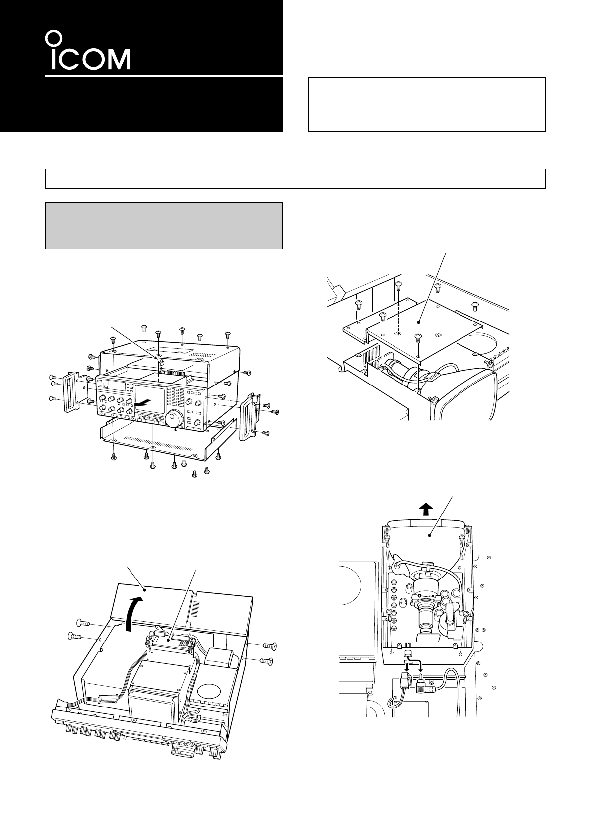
q Remove the rac k mounting handles, top/bottom cov-
ers and front panel as shown in the diagram below.
w Remove the speaker cab le as sho wn in the diagram
below.
e Remove the 4 screws and open the RFA/TV units
as shown in the diagram below.
r Remove the 4 screws and remove the SW-D unit as
shown in the diagram below.
t Remove the 6 screws from the DISPLAY unit (CRT)
and remove the cover as shown in the diagram
below.
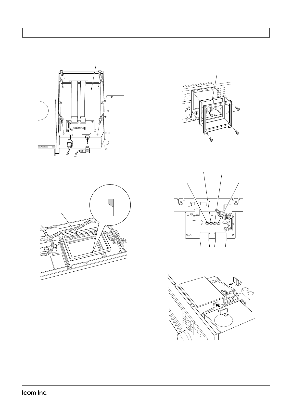
y Remove the 4 screws and 2 connectors from the
DISPLAY unit (CRT) and remove the unit as shown
in the diagram below.
INSTALLATION
RWARNING: DISCONNECT the AC power
cable and wait several minutes before opening the
receiver.
Speaker cable
DISPLAY unit cover
RF A/TV unit
SW-D unit
DISPLAY unit
Page 2
6-9-16 Kamihigashi, Hirano-ku, Osaka 547-0002 Japan
Count on us!
INSTALLATION (continued)
A-8333Ι-1EX Printed in Japan
© 1999 Icom Inc.
u Connect 2 connectors to the LCD unit and place the
unit using the 4 screws.
i Replace the rubber spacer from the backside of the
front panel with the supplied one.Take care of the
direction.
o Remove the 4 screws from the front panel and re-
place the CRT screen filter with the LCD screen filter as shown in the diagram below. Assemble the
front panel.
!0 Adjust the contrast, color, tint and brightness using
the controls as shown below, if desired.
!1 Replace the DISPLAY unit cover and attach the
cable clamp as shown below. Clamp the cables.
!2 Replace the RFA/TV units and SW-D unit.
!3 Replace the top/bottom covers and the rack mount-
ing handles.
LCD unit
Rubber spacer
Front
side
Rear
side
Top
LCD screen filter
[CONTRAST]
[COLOR] [TINT]
[BRIGHT]
 Loading...