

Page 1
INSTRUCTIONS
POWER AMPLIFIER UNITS
UR-PA5000
Thank you for purchasing the UR-PA5000/URPA6000 POWER AMPLIFIER UNITS for the IC-FR5000/IC-
FR6000 series repeaters.
Please read these instructions and the repeater’s
instruction manual carefully before installing the
units and operating the repeater.
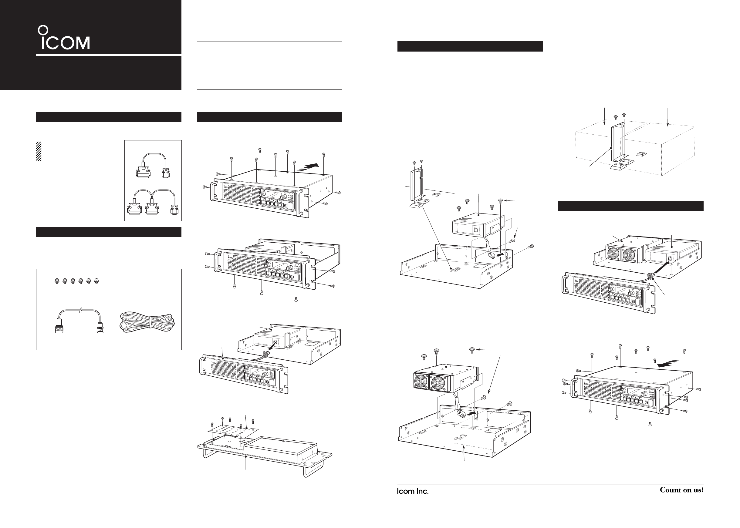
q Set screws (M3×6 mm) ........................................6
w Coaxial cable (OPC-2243) ...................................1
e DC power cable....................................................1
q
Remove the 7 screws from top and the 2 screws
from each side of the repeater, then slide off the top
cover to the direction of the arrow.
w Remove the 3 screws from bottom and the 2
screws from each side of the repeater.
e Disconnect the control cable from the channel
module, then remove the front panel.
r Remove the 5 screws to remove the front plate off.
SUPPLIED ACCESSORIES
OPENING CASE
UR-PA6000
Icom, Icom Inc. and the Icom logo are registered trademarks of Icom Incorporated (Japan) in Japan, the United States, the United Kingdom, Germany,
France, Spain, Russia and/or other countries.
All other products or brands are registered trademarks or trademarks of their
respective holders.
• FOR CLASS A UNINTENTIONAL RADIATORS:
This equipment has been tested and found to comply with
the limits for a Class A digital device, pursuant to part 15
of the FCC Rules. These limits are designed to provide reasonable protection against harmful interference when the
equipment is operated in a commercial environment. This
equipment generates, uses, and can radiate radio frequency
energy and, if not installed and used in accordance with the
instruction manual, may cause harmful interference to radio
communications.
Operation of this equipment in a residential area is likely to
cause harmful interference in which case the user will be required to correct the interference at his own expense.
1-1-32 Kamiminami, Hirano-ku, Osaka 547-0003, Japan
A-7027H-1EX-w Printed in Japan
© 2012–2013 Icom Inc.
LOCATING THE UNIT
Before installing the power amplifi er unit, relocation of the channel module is necessary.
Otherwise, the amplifi er's ventilation system
will not work properly and may damage the
unit.
q Detach the support bracket by removing the set
screws, as illustrated below.
w Detach the channel module by removing the 2 tap-
ping screws and the 3 set screws.
e Reinstall the module on the right side (front view)
of the base with the 2 tapping screws and 4* set
screws.
* Use one of the support bracket's set screws to reinstall.
r Install the power amplifier unit with the fans facing
the front of the repeater.
• Tighten only 5 set screws at this time, as illustrated
below.
Set screws
Power amplifier unit
Channel module
t When both module and amplifier are installed, at-
tach the support bracket with the set screws to the
original location, on the amplifier's angle.
• The inmost part of the bracket will be tightened along
with the amplifi er's angle.
q Connect the control cable to the channel module.
w Return the front panel, top cover and screws to
their original positions.
ASSEMBLE THE UNIT
REQUIRED
NOTE: The cables are not
supplied with the the power
amplifier unit.
• OPC-2202
CONNECTION CABLE
Connects between the repeater
unit and the PA unit.
• OPC-2203
CONNECTION CABLE
Connects between the repeater
unit, the PA unit and the external
equipment, if used.
Before installing the power amplifier unit, one of the following
cables is required.
OPC-2202
OPC-2203
q
P
0
P
1
P
2
P
3
P
4
P
0
P
1
P
2
P
3
P
4
Support bracket
Channel module
Set screws
Tapping
screws
Power amplifier unit
Channel module
Support bracket
Power amplifier unit
Channel module
w
e
Channel module
Front panel
P
0
P
1
P
2
P
3
P
4
Front plate
Front panel
P
0
P
1
P
2
P
3
P
4
Control cable
P
0
P
1
P
2
P
3
P
4
Page 2
REAR PANEL CONNECTION
OPC-2203
POWER SUPPLY CONNECTION
Make sure the repeater's power is turned OFF before
connecting a DC power cable.
CAUTION: Voltages greater than 16 V DC will
damage the repeater. Check the source voltage
before connecting the power cable.
R When you disconnect the DC power cable, take care to
not break your fi ngernail.
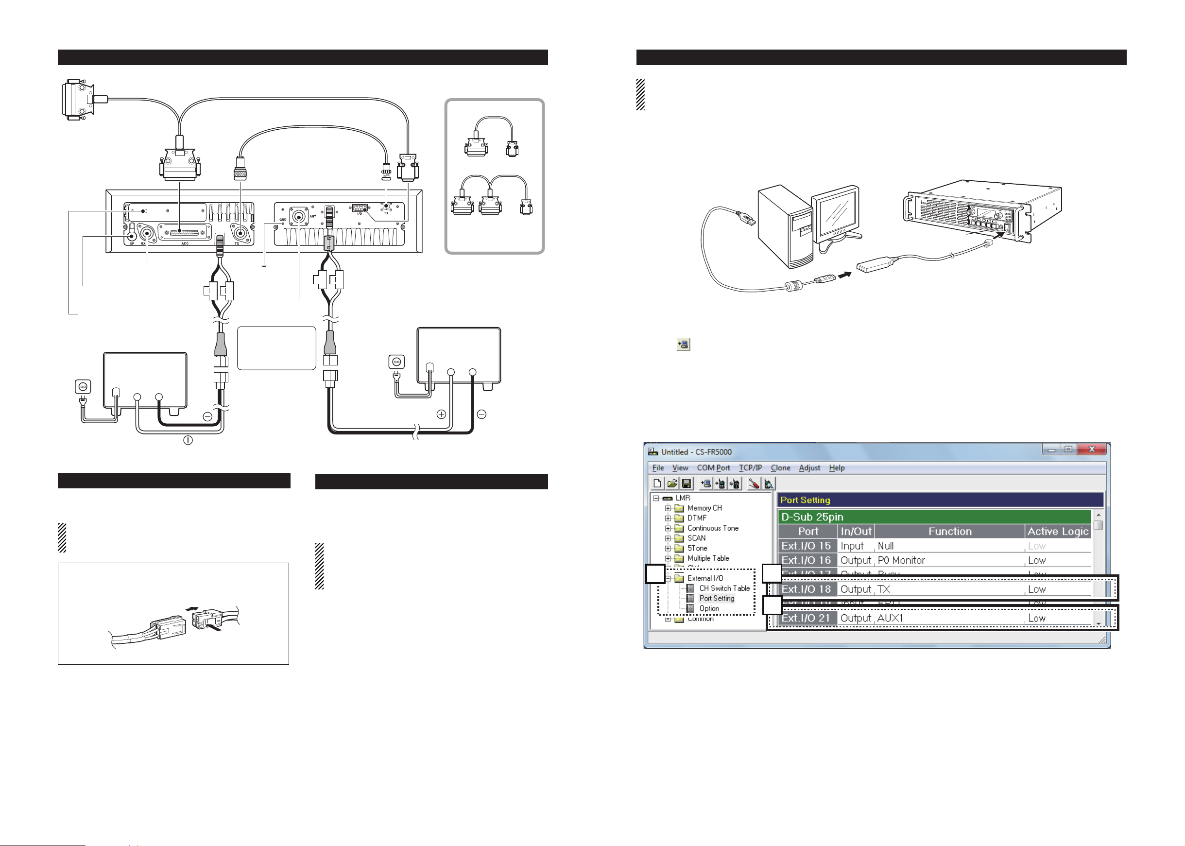
CLONE SETTING
NOTE: Before operating the repeater with the power amplifi er unit installed, the following settings are necessary
using the CS-FR5000
CLONING SOFTWARE in addition to the usual repeater settings. Refer to the instruction
manual of the CS-FR5000 for more details.
LINE FUSE REPLACEMENT
The UR-PA5000/UR-PA6000 is equipped with 30 A
fuses. If the fuses blow, fi nd and repair the problem,
then install new fuses with the same ratings.
CAUTION: USE specifi ced fuses only.
CAUTION: DISCONNECT the DC power cable
from the amplifi er. Otherwise, there is danger of an
electric shock and/or equipment damage.
e Read all the transceiver’s data before beginning
the setting, even when the transceiver is factory
fresh.
• Click , or click “Clone” in the top menu of the cloning software, and then select “Read <- TR” to read.
• While reading or writing the cloning data, NEVER turn
OFF the transceiver or the PC, and NEVER disconnect
the cloning cable. Otherwise, the data could be lost or
deleted.
r
Open “Memory CH,” and set the RF PWR as
“L1.”
• Adjust the output power to 5 W.
t Open “Ports Setting” in the “External I/O” folder,
as shown below.
y Set “Ext.I/O18” with “Output” as In/Out, “TX” as
the Function and “Low” as the Active Logic.
u Set “Ext.I/O21” with “Output” as In/Out, “AUX1”*1
as the Function and “Low”*2 as the Active Logic.
*1 Select a port between AUX1 through 4 that is not se-
lected for other functions.
*
2
For the 100 W output version, select “High” as the Ac-
tive Logic.
q Connect the cloning cable, as illustrated below.
w Push [PWR] to turn ON the power.
(Option)
OPC-2202
(Option)
OPC-2202
Connects to external
equipment, if used.
To [ACC]
Connects to
an RX antenna.
Connects to a 4 ˘
external speaker.
Connects to a dPMR
control unit, if used.
DC power supply
AC outlet
13.2 V; at least 10 A
Red
AC cable
OPC-2243
To [TX]
20 A
fuses
GND
Connects to
30 A
fuses
a TX antenna
CAUTION:
NEVER remove the
fuse holders from the
DC power receptacle.
Black
_
+
Black
Red
Supplied
DC power cable
Supplied
DC power cable
AC outlet
AC cable
[I/O]To [TX]
DC power supply
13.2 V; at least 30 A
Red
To
OPC-2203
If external equipment
is used, an OPC-2203
must be used.
Black
Red
_
+
Black
PC
to USB port
P
0
P
1
P
2
P
3
P
4
[PWR]
to [MIC] connector
OPC-1122U
(USB type)
w
q Push
t
y
u
 Loading...