

Page 1
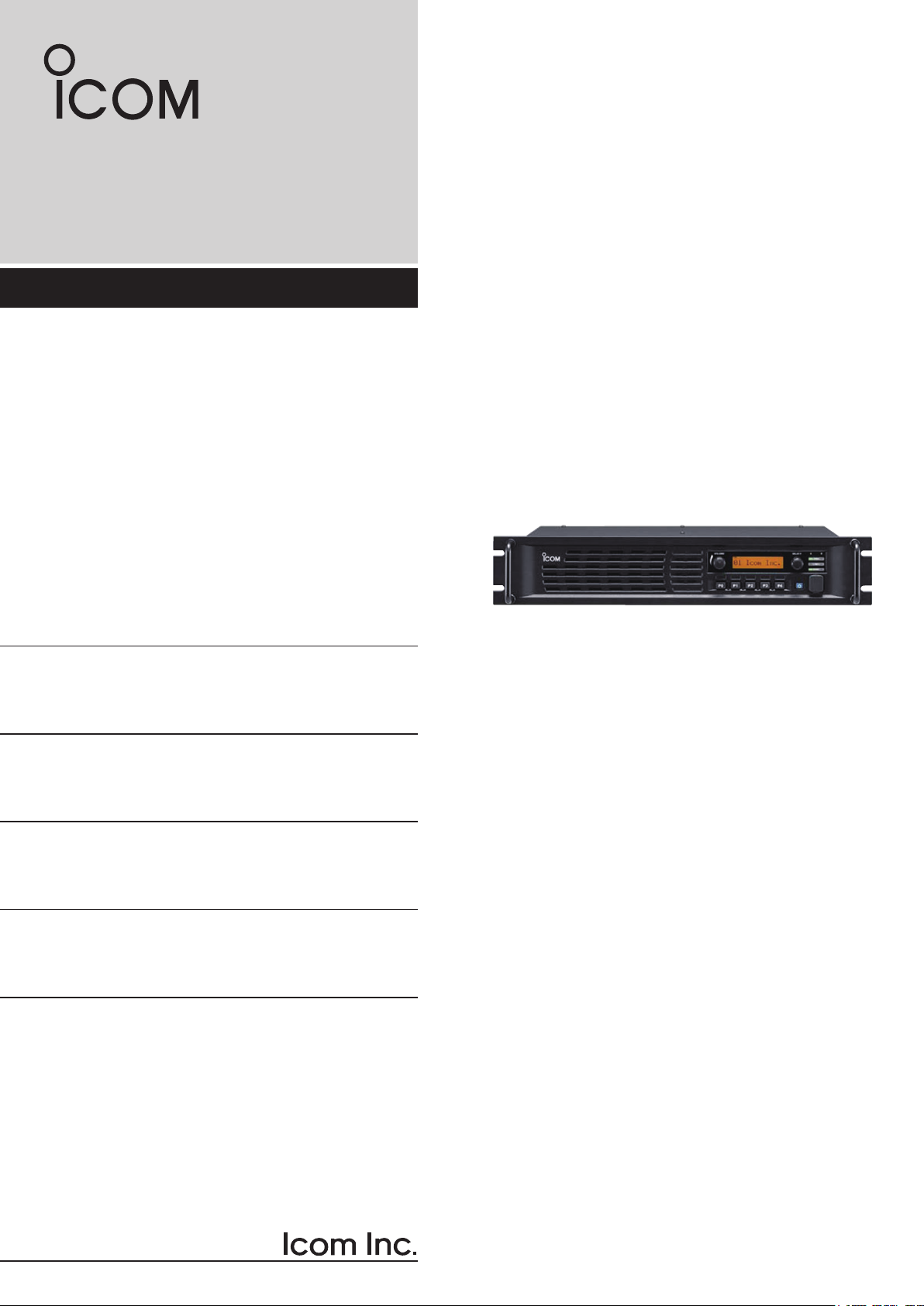
INSTRUCTION MANUAL
VHF DIGITAL REPEATER
iFR5300
UR-FR5300
UHF DIGITAL REPEATER
iFR6300
UR-FR6300
IC-FR5300/IC-FR6300
Page 2
Thank you for choosing this Icom product.
This product is designed and built with Icom’ s state
of the art technology and craftsmanship. With proper
care, this product should provide you with years of
trouble-free operation.
IMPORTANT
READ THIS INSTRUCTION MANUAL
CAREFULLY before attempting to operate the re-
peater.
D FEATURES
m Up to 2 channels of operation
You can install a channel extension module (op-
tional UR-FR5300/UR-FR6300) into a repeater.
Two channels can be operated on the same repeater when a channel extension module is installed.
m Built-in 5-Tone, DTMF encoder & decoder
Multiple signaling systems are built-in as standard.
These systems are fully compatible with Icom Fseries radios.
m DTMF remote control capability
You can control the repeater from a remote location
over the air or over a phone line with DTMF.
m D-Sub 25 pin ACC port equipped
You can use optional equipment through the D-sub
25 pin ACC port on the repeater’s rear panel.
m Online control and Digital Trunking opera-
tion
Online control and digital trunking operation are
available when the optional UC-FR5300 trunking/
network controller is installed in the repeater.
SAVE THIS INSTRUCTION MANUAL– This
manual contains important safety and operating instructions for the IC-FR5300/UR-FR5300/IC-FR6300/
UR-FR6300 vhf/uhf digital repeaters.
EXPLICIT DEFINITIONS
WORD DEFINITION
RWARNING!
CAUTION
NOTE
Personal injury, fire hazard or electric
shock may occur.
Equipment damage may occur.
If disregarded, inconvenience only. No risk
of personal injury, fire or electric shock.
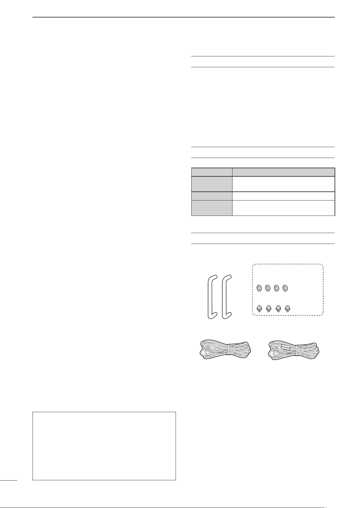
SUPPLIED ACCESSORIES
The following accessories are supplied.
Handles For handles attachment
Spacers
m Other features
-
Wide frequency coverage
<VHF>
IC-FR5300/UR-FR5300
: 136 to 174 MHz
<UHF>
IC-FR6300/UR-FR6300
: 330 to 400 MHz,
400 to 470 MHz,
450 to 512 MHz,
450 to 520 MHz
- PC programmable
- 19 inch rack mount
Icom is not responsible for the destruction or damage
to the Icom transceiver, if the malfunction is because
of:
• Force majeure, including, but not limited to, fires,
earthquakes, storms, floods, lightning, other natural disasters, disturbances, riots, war, or radioactive
contamination.
• The use of Icom transceivers with any equipment
that is not manufactured or approved by Icom.
i
Screws
DC power cable
(OPC-1784)
Icom, Icom Inc. and the Icom logo are registered trademarks
of Icom Incorporated (Japan) in Japan, the United States, the
United Kingdom, Germany, France, Spain, Russia, Australia,
New Zealand, and/or other countries.
All other products or brands are registered trademarks or
trademarks of their respective holders.
DC power cable
(CAB-1149)
Page 3

PRECAUTIONS
TABLE OF CONTENTS
R WARNING HIGH VOLTAGE! NEVER touch an an-
tenna or internal antenna connector while transmitting.
This could cause an electrical shock or RF burn.
R WARNING HIGH VOLTAGE! NEVER install the an-
tenna at any place that person easily touch the antenna while transmitting. This could cause an electrical
shock or RF burn.
R WARNING! NEVER apply AC power to the DC
power receptacle on the repeater rear panel. This
could cause a fire or damage the repeater.
R WARNING! NEVER apply more than 16 V DC to
the DC power receptacle on the repeater rear panel.
This could cause a fire or damage the repeater.
R WARNING! NEVER reverse the DC power cable
polarity. This could cause a fire or damage the repeater.
R WARNING! NEVER let metal, wire or other objects
contact the inside of the repeater, or make incorrect
contact with connectors on the rear panel. This could
cause an electric shock or damage the repeater.
CAUTION: DO NOT place or leave the repeater in
areas with temperatures below –30°C (–22°F) or above
+60°C (+140°F). Be aware that temperatures can exceed 80°C (+176°F), resulting in permanent damage
to the repeater if left there for extended periods.
CAUTION: DO NOT place or leave the repeater in excessively dusty environments. This could damage the
repeater.
CAUTION: DO NOT put anything on top of the repeater. This will obstruct heat dissipation.
CAUTION: DO NOT set the repeater’s RF output
power to more than your external linear amplifier’s
maximum input level, if you use one. Otherwise, a high
input could damage the linear amplifier.
CAUTION: DO NOT use non-Icom microphones.
Other manufacturer’s microphones may have different pin assignments, and could damage the connector
and/or the repeater.
BE CAREFUL! The heatsink will become hot when
continuously operating the repeater for long periods
of time.
NEVER expose the repeater to rain, snow or any liquids.
NEVER leave the repeater in an insecure place to
avoid use by unauthorized persons.
IMPORTANT ............................................................... i
EXPLICIT DEFINITIONS ............................................ i
SUPPLIED ACCESSORIES.......................................i
PRECAUTIONS .........................................................ii
SAFETY TRAINING INFORMATION ....................... iii
INFORMATIONS EN MATIÈRE DE SÉCURITÉ ...... iv
1 PANEL DESCRIPTION ............................. 1–3
n Front panel ........................................................ 1
D Function display ............................................ 2
n Rear panel ......................................................... 2
D Accessory connector .................................... 3
2 INSTALLATION AND CONNECTIONS .... 4–6
n Unpacking ......................................................... 4
n Selecting a location ........................................... 4
n Antenna connection .......................................... 4
n Front panel connection ...................................... 5
n Rear panel connection ...................................... 5
n Power supply connection .................................. 6
n Mounting the repeater ....................................... 6
D Using the supplied handles ........................... 6
n Fuse replacement ............................................. 6
D Line fuse replacement ................................... 6
3 OPERATION ................................................. 7
n Receiving and transmitting ................................ 7
D Repeater operation ....................................... 7
D Base station operation .................................. 7
4 MAINTENANCE ............................................ 8
n Troubleshooting ................................................. 8
5 OPTIONS ...................................................... 9
6 INFORMATION ........................................... 10
n Voice cording technology ................................ 10
n FCC information .............................................. 10
1
2
3
4
5
6
7
8
9
10
11
12
13
14
15
16
17
18
19
20
ii
21
Page 4

SAFETY TRAINING INFORMATION
Your Icom radio generates RF electro-
magnetic energy during transmit
mode. This radio is designed for and
WARNING
• For compliance with FCC and IC RF Exposure Requirements, the transmitter antenna installation shall
comply with the following three conditions:
1. The transmitter antenna gain shall not exceed
0 dBi.
2. IC-FR5300/UR-FR5300:
Transmit only when people are at least the recom-
mended minimum distance of 60 centimeters away
from the properly installed antenna. This separation distance will ensure that there is sufficient distance from a properly installed externally-mounted
antenna to satisfy the RF exposure requirements
in the applicable RF exposure compliance standards.
2. IC-FR6300/UR-FR6300:
Transmit only when people are at least the recom-
mended minimum distance of 50 centimeters away
from the properly installed antenna. This separation distance will ensure that there is sufficient distance from a properly installed externally-mounted
antenna to satisfy the RF exposure requirements
in the applicable RF exposure compliance standards.
classified as “Occupational Use Only,”
meaning it must be used only during
the course of employment by individuals aware of the hazards, and the ways
to minimize such hazards.
This radio is NOT intended for use by
the “General Population” in an uncontrolled environment.
To ensure that your exposure to RF
electromagnetic energy is within the
FCC and IC allowable limits for occu-
CAUTION
• DO NOT operate the radio without a proper antenna
attached, as this may damage the radio and may also
cause you to exceed FCC and IC RF exposure limits.
A proper antenna is the antenna supplied with this
radio by the manufacturer or an antenna specifically
authorized by the manufacturer for use with this radio.
• DO NOT transmit for more than 50% of total radio
use time (“50% duty cycle”). Transmitting more than
50% of the time can cause FCC and IC RF exposure
compliance requirements to be exceeded. The radio
is transmitting when the “TX indicator” lights red. You
can cause the radio to transmit by pressing the “PTT”
switch.
Electromagnetic Interference/Compatibility
During transmissions, your Icom radio generates RF
energy that can possibly cause interference with other
devices or systems. To avoid such interference, turn off
the radio in areas where signs are posted to do so. DO
NOT operate the transmitter in areas that are sensitive
to electromagnetic radiation such as hospitals, aircraft,
and blasting sites.
pational use, always adhere to the following guidelines:
iii
Page 5

INFORMATIONS EN MATIÈRE DE SÉCURITÉ
AVERTISSEMENT
MISE EN GARDE
Votre radio Icom produit une énergie
électromagnétique de radiofréquences (RF), en mode de transmission. Cette radio est conçue pour un
«usage professionnel seulement» et
classée comme tel, ce qui signifie
qu’elle doit être utilisée uniquement
dans le cadre d’un travail par des
personnes conscientes des dangers
et des mesures visant à minimiser
ces dangers. Elle N’EST PAS conçue
pour une «utilisation grand public»,
dans un environnement non
contrôlé.
• Afin de satisfaire aux exigences de la FCC et d’IC
en matière d’exposition aux RF, il est nécessaire que
l’antenne soit installée conformément aux trois conditions suivantes:
1.
Le gain de l’antenne du radio émetteur ne doit pas
dépasser 0 dBi.
2. IC-FR5300/UR-FR5300:
Transmettre que lorsque les gens sont au moins
la distance minimale recommandée de 60 centimètres de l'antenne est correctement installé.
Cette distance de sécurité assurera que les personnes soient placées suffisamment loin d’une
antenne correctement fixée à l’extérieur pour satisfaire aux exigences en matière d’exposition aux
RF, en vertu des normes de conformité applicables.
2. IC-FR6300/UR-FR6300:
Transmettre que lorsque les gens sont au moins
la distance minimale recommandée de 50 centimètres de l'antenne est correctement installé.
Cette distance de sécurité assurera que les personnes soient placées suffisamment loin d’une
antenne correctement fixée à l’extérieur pour satisfaire aux exigences en matière d’exposition aux RF,
en vertu des normes de conformité applicables.
Afin de vous assurer que votre exposition à une énergie électromagnétique de RF se situe dans les limites
permises par la FCC et d’IC pour une
utilisation grand public, veuillez en
tout temps respecter les directives
suivantes:
• NE PAS faire fonctionner la radio sans qu’une
antenne appropriée y soit fixée, car ceci risque
d’endommager la radio et causer une exposition
supérieure aux limites établies par la FCC et d’IC.
L’antenne appropriée est celle qui est fournie avec
cette radio par le fabricant ou une antenne spécialement autorisée par le fabricant pour être utilisée
avec cette radio.
• NE PAS émettre pendant plus de 50% du temps
total d’utilisation de l’appareil («50% du facteur
d’utilisation»). Émettre pendant plus de 50% du
temps total d’utilisation peut causer une exposition
aux RF supérieure aux limites établies par la FCC
et d’IC. Lorsque le voyant DEL rouge s’allume,
cette radio est en train d’émettre. La radio émettra
si vous appuyez sur le bouton du microphone.
Interférence électromagnétique et compatibilité
En mode de transmission, votre radio Icom produit de
l’énergie de RF qui peut provoquer des interférences
avec d’autres appareils ou systèmes. Pour éviter de
telles interférences, mettez la radio hors tension dans
les secteurs où une signalisation l’exige. NE PAS faire
fonctionner l’émetteur dans des secteurs sensibles au
rayonnement électromagnétique tels que les hôpitaux,
les aéronefs et les sites de dynamitage.
1
2
3
4
5
6
7
8
9
10
11
12
13
14
15
16
17
18
19
20
21
iv
Page 6

1
P0P1P2P3P
4
qw e
i uo
Function
display
y
t
r
PANEL DESCRIPTION
n Front panel
q INTERNAL SPEAKER
Outputs the received audio.
w VOLUME CONTROL [VOLUME] (p. 7)
Adjusts the audio output level.
e SELECTOR DIAL [SELECT]
Rotate to adjust the squelch threshold level, select
the operating channel. (Depending on the presetting.)
r POWER INDICATOR [POWER]
➥ Lights green at ‘A’ module's indicator while the
repeater power is turned ON.
When a channel extension module is installed:
➥ Lights green at the selected module indicator
(‘A’ or ‘B’) while the repeater power is turned
ON.
➥ Lights orange at the un-selected module indica-
tor (‘A’ or ‘B’) while the repeater power is turned
ON.
t TRANSMIT INDICATOR [TX]
Lights red while transmitting.
y BUSY INDICATOR [BUSY]
Lights green while receiving a signal or when the
noise squelch is open.
About [PWR], [TX] and [BUSY] indicators:
‘A’ and ‘B’ modules indicators are usable for these
indications. ‘A’ module's indicator corresponds to
the original module, and ‘B’ module's indicator corresponds to an extended module.
u
MICROPHONE CONNECTOR [MIC]
This 8-pin modular jack accepts an optional micro-
phone.
KEEP the [MIC] connector cover attached to the
repeater when an optional microphone is not
used.
q +8 V DC output (Max. 15 mA)
w Output port for PC programming
q
(Front panel view)
i POWER SWITCH [POWER]
➥ Push to turn ON the repeater power.
➥ Hold down for 3 seconds to turn OFF the re-
When a channel extension module is installed:
➥ While the repeater power is turned ON, push
• The power indicator of the selected module unit
o DEALER-PROGRAMMABLE KEYS
Desired functions can be independently preset by
your dealer.
Ask your dealer for details.
• Because these keys are programmable, the functions
are unique to each unit.
i
e NC
r M PTT (Input port for TX control)
t Microphone ground
y Microphone input
u Ground
i Input port for PC programming
peater power.
to select the desired module to operate the repeater as the base station.
lights green.
1
Page 7

we ryt
The optional channel extention module
can be installed.
Ask your dealer for details.
The optional trunking/network controller
can be installed.
Ask your dealer for details.
q
D Function display
qwer
PANEL DESCRIPTION
1
ICOM Inc.
q SIGNAL STRENGTH INDICATOR
Indicates the relative signal strength level.
w LOW POWER INDICATOR
Displays when the low output power is selected.
e AUDIBLE INDICATOR
Displays when the channel is in the ‘audible’ (un-
mute) mode.
n Rear panel
t
y
r GNSS INDICATOR
Displays when the UC-FR5300 is installed, and the
GNSS (Global Navigation Satellite System) positioning is established.
This indicator can be deactivated using programing
software.
t ALPHANUMERIC DISPLAY
Shows a variety of text or code information.
y KEY ICON
Displays when the key assigned as the [Lock] or
[Tx Disable] key and it is active.
1
2
3
4
5
6
7
8
9
The repeater rear panel may be different, depending on the repeater’s version.
q DC POWER CONNECTOR (For cooling fans)
Connects to the supplied CAB-1149 DC power
cable from this connector to an external 13.6 V DC
power source to activate the cooling fans.
See page 5 for the connection details.
w
EXTERNAL SPEAKER CONNECTOR [SP]
Connects to the optional SP-35.
e RECEIVE ANTENNA CONNECTOR [RX]
Connects to a receive antenna (impedance: 50 ø).
r ACCESSORY CONNECTOR [ACC]
Connects to the accessory connector.
• See p. 3 for accessory connector information.
t DC POWER RECEPTACLE
Connects to the supplied OPC-1784 DC power
cable from an external 13.6 V DC power source.
See page 5 for the connection details.
y TRANSMIT ANTENNA CONNECTOR [TX]
Connects to a transmit antenna (impedance: 50 ø).
10
11
12
13
14
15
16
17
18
19
20
21
2
Page 8

1
PANEL DESCRIPTION
D Accessory connector
!4 @5
q!3
Pin No. Pin Name Description Specication
1 NC No connection —
2 TXD Input terminal for serial communication data. —
3 RXD Output terminal for serial communication data. —
4 RTS Input terminal for request-to-send data. —
5 CTS Output terminal for clear-to-send data. —
6 NC No connection —
7 GND Serial/digital signal ground —
8 MOD IN Modulator input from an external terminal unit. Input level: 300 mV rms
9 DISC OUT
10 EXT. D/A
11 VCC 13.6 V DC output Output current: Less than 100 mA
12 NC No connection —
13 NC No connection —
14 GND Ground —
15 EXT.I/O 15 The desired function can be assigned.* (Default: Null) +5 V pull up, Active=L
16 EXT.I/O 16
17 EXT.I/O 17 The desired function can be assigned.* (Default: Busy Output) +5 V pull up, Active=L
18 EXT.I/O 18 The desired function can be assigned.* (Default: Null) +5 V pull up, Active=L
19 EXT.I/O 19 The desired function can be assigned.* (Default: EPTT Input) +5 V pull up, Active=L
20 NC No connection —
21 EXT.I/O 21
22 AF OUT The AF detector Output. —
23 EXT.I/O 23
24 EXT.I/O 24 The desired function can be assigned.* (Default: Null) +5 V pull up, Active=L
25 EXT.I/O 25
Output terminal for AF signals from the AF detector circuit.
Output level is xed, regardless of the [AF] control setting.
Output terminal.
The desired function can be assigned.* (Default: Null)
The desired function can be assigned.*
(Default: P0 Monitor Output)
The desired function can be assigned.*
(Default: Analog Audible Output)
The desired function can be assigned.*
(Default: Mic Mute Output)
The desired function can be assigned.*
(Default: Mic Hanger Output)
Output level: 300 mV rms
—
+5 V pull up, Active=L
+5 V pull up, Active=L
+5 V pull up, Active=L
+5 V pull up, Active=L
* The desired function can be assigned using the optional CS-FR5300 cloning software. Ask your dealer for details.
3
Page 9

INSTALLATION AND CONNECTIONS
2
n Unpacking
After unpacking, immediately report any damage to
the delivering carrier or dealer. Keep the shipping cartons.
For a description and a diagram of accessory equipment included with the repeater, see ‘SUPPLIED ACCESSORIES’ on page i of this manual.
n Selecting a location
Select a location for the repeater that allows adequate
air circulation, free from extreme heat, cold, or vibrations, and away from TV sets, TV antenna elements,
radios and other electromagnetic sources.
n Antenna connection
For radio communications, the antenna is a critical
component, along with output power and sensitivity.
Select antenna(s), such as a well-matched 50 ø antenna, and feedline. 1.5:1 or better of Voltage Standing Wave Ratio (VSWR) is recommended for the desired band. Of course, the transmission line should be
a coaxial cable.
CAUTION: DO NOT install the repeater without a
lightning arrestor to help protect the repeater from
lightning.
NOTE: There are many publications that describe
proper antennas and their installation. Check with
your local dealer for more information and recommendations.
1
2
3
4
5
6
7
8
9
10
11
12
13
14
15
16
17
18
4
19
20
21
Page 10

k
2
INSTALLATION AND CONNECTIONS
n Front panel connection
HM-152 HAND
MICROPHONE
(optional)
SM-26 DESKTOP
MICROPHONE
(optional)
n Rear panel connection
EXTERNAL SPEAKER
4 ø external speaker.
P0P1P2P3P
MICROPHONE CONNECTOR (Front panel view)
q +8 V DC output (Max. 15 mA)
w Output port for PC programming
i
q
CAUTION: DO NOT short pin 1 to ground as this can
damage the internal 8 V regulator. DC voltage is applied
to pin 1 for microphone operation. Only Icom microphones are recommended.
[RX ANT]
(p. 4)
e NC
r M PTT (Input port for TX control)
t Microphone ground
y Microphone input
u Ground
i Input port for PC programming
ACC CONNECTOR (p. 3)
Used for external equipment
control.
4
[TX ANT] (p. 4)
Supplied
1 A
fuses
To a 13.6 V
DC power source
*This connection may not be required, depending on the repeater version.
The repeater rear panel may be different, depending on the repeater version.
5
Red
Black
R When you disconnect the
DC power cable, take care to
not crack of your fingernail.
DC power
cable (CAB-1149)*
R WARNING!
NEVER remove the
fuse-holder from the
DC power receptacle or cable.
w
q Push
20 A
fuses
AC cable
Supplied
DC power cable (OPC-1784)
DC power supplyAC outlet
13.6 V; at least 20 A
Black
Red
_
+
Red
Blac
Page 11

INSTALLATION AND CONNECTIONS
.
2
n Power supply connection
Make sure the repeater’s power is turned OFF when
connecting a DC power cable.
R WARNING! NEVER apply more than 16 V DC to
the DC power receptacle on the repeater rear panel.
This could cause a fire or damage the repeater.
n Mounting the repeater
D Using the supplied handles
The supplied handles are used when mounting the repeater into a 19 inch rack. The handles are installed on
the repeater’s front panel.
q Attach the supplied handles to both sides of the re-
peater’s front panel with the spacers, then tighten
the screws as shown below.
P
0
P
1
P
2
P
3
P
4
Screw
Handle
Spacer
w The completed installation should look like the illus-
tration below.
1
2
3
4
5
6
n Fuse replacement
If a fuse blows, or the repeater stops functioning, find
the source of the problem, repair it and then replace
the damaged fuse with a new rated one.
D Line fuse replacement
Fuse rating: 20 A
USE only a 20 A fuse
P
0
P
1
P
2
P
3
P
4
CAUTION: DO NOT replace the fuse with the DC
power cable connected to the repeater. Disconnect
the cable to prevent electric shock and/or equipment damage.
7
8
9
10
11
12
13
14
15
16
17
18
19
20
21
6
Page 12

3
OPERATION
n Receiving and transmitting
D Repeater operation
Ask your dealer for details of the repeater’s presettings.
➥ When the power is turned ON, the [PWR] indicator
lights green. (p. 1)
➥ The [TX] or [BUSY] indicator lights simultaneously
while transmitting/receiving a signal.
• The [TX] indicator lights red.
• The [BUSY] indicator lights green.
NOTE: A power amplifier protector is built into the
repeater. The protector is activated when the repeater temperature becomes extremely high due to
long periods of transmitting to reduce the transmit
output power level. The output power will return to
its normal level when the repeater has cooled
down.
D Base station operation
Receiving
q Push [POWER] to turn ON the power.
w Set the audio and squelch levels.
➥ Rotate [SELECT]*1 fully counterclockwise in ad-
vance.
➥ Rotate [VOLUME] to adjust the audio output
level.
➥ Rotate [SELECT]*1 clockwise until the noise just
disappears.
e Push [CH Up]*2 or [CH Down]*2 to select the de-
sired channel.
• When receiving a signal, the [BUSY] indicator lights
green and audio is heard from the speaker.
• Further adjustment of [VOLUME] to a comfortable listening level may be necessary at this point.
1
*
When the [SQL Level Up/Down] key function is assigned
to [SELECT].
2
*
When the [CH Up]/[CH Down] key functions are as-
signed.
Transmitting
q Take the microphone off hook.
w Wait for the channel to become clear.
e Hold down [PTT] to transmit, then speak into the
microphone at your normal voice level.
r Release [PTT] to receive.
IMPORTANT:
To maximize the audio quality of the transmitted
signal:
1. Pause briefly after pushing [PTT].
2. Hold the microphone 5 to 10 cm (2 to 4 inch)
from your mouth, then speak at your normal
voice level.
7
Page 13

n Troubleshooting
MAINTENANCE
4
The following chart is designed to help you correct
problems that are not equipment malfunctions.
PROBLEM POSSIBLE CAUSE SOLUTION REF.
Power does not come
on when [POWER] is
pushed.
No sound comes from
the speaker.
Sensitivity is low and
only strong signals
are audible.
Received audio is unclear or distorted.
Output power is too
low.
No contact possible
with another station.
• DC power cable is improperly connected.
• Fuse is blown.
• Volume level is too low.
• The squelch is closed.
• The audio mute function is activated.
• A selective call or squelch function is activated such as 5-tone call or tone squelch.
• The front speaker is set to OFF.
• Antenna feedline or the antenna connector has a poor contact or is short-circuited.
• Optional voice scrambler is turned OFF.
• Scrambler code is not set correctly.
• Output power is set to Low.
• Power amplifier protection circuit is activated.
• The other station is using tone squelch.
• The operation mode is set to the Full-duplex mode. (Base station operation)
If you are unable to locate the cause of a problem
or solve it through the use of this chart, contact your
nearest Icom Dealer or Service Center.
• Re-connect the DC power cable correctly.
• Find the cause and repair it, then replace the
fuse with a rated one.
• Rotate [VOLUME] clockwise to obtain a suitable listening level.
• While in the base operating mode, rotate
[SELECT] to counterclockwise to open the
squelch. (When the [SQL Level Up/Down] key
function is assigned to [SELECT].)
• Push [MONI] (if assigned) to turn the audio
mute function OFF.
• Turn OFF the appropriate function.
• Turn ON the front speaker using the optional
CS-FR5000
dealer for details.
• Check and reconnect (or replace if necessary), the antenna feedline or antenna connector.
• Turn ON the optional voice scrambler.
• Reset the scrambler code.
• Push [HIGH/LOW] (if assigned) to select
High power.
• Cool down the repeater or stop accessing the
repeater until it has cooled down.
• Turn the tone squelch function ON.
• Set the operation mode to the Simplex mode,
if the other station is in the Simplex mode.
clo nin g soft ware . Ask your
pp.
5, 6
p. 8
p. 7
p. 7
p. 5
1
2
–
–
–
3
4
5
6
7
–
–
8
9
–
10
–
11
–
–
12
13
8
14
15
16
17
18
19
20
21
Page 14

5
• SP-35 external speaker
Compact and easy-to-install.
Input impedance: 4 ø
Rated input: 5 W
Maximum input: 7 W
• HM-152 hand microphone
• SM-26 desktop microphone
• UR-FR5300/UR-FR6300 channel extension modules
• UC-FR5300 trunking/network controller
Some options may not be available in some countries.
Please ask your dealer for details.
OPTIONS
9
Page 15

n Voice coding technology
The AMBE+2™ voice coding Technology embodied in
this product is protected by intellectual property rights
including patent rights, copyrights and trade secrets
of Digital Voice Systems, Inc. This voice coding Technology is licensed solely for use within this Communications Equipment.
The user of this Technology is explicitly prohibited
from attempting to extract, remove, decompile, reverse engineer, or disassemble the Object Code, or in
any other way convert the Object Code into a humanreadable form. U.S. Patent Nos.
#8,595,002, #8,359,197, #8,315,860, #8,200,497,
#7,970,606, and #6,912,495 B2.
INFORMATION
6
1
2
n FCC information
This equipment has been tested and found to comply
with the limits for a Class B digital device, pursuant to
part 15 of the FCC Rules. These limits are designed
to provide reasonable protection against harmful interference in a residential installation. This equipment
generates, uses and can radiate radio frequency energy and, if not installed and used in accordance with
the instructions, may cause harmful interference to
radio communications. However, there is no guarantee that interference will not occur in a particular installation. If this equipment does cause harmful interference to radio or television reception, which can be
determined by turning the equipment off and on, the
user is encouraged to try to correct the interference
by one or more of the following measures:
• Reorient or relocate the receiving antenna.
• Increase the separation between the equipment and
receiver.
• Connect the equipment into an outlet on a circuit different from that to which the receiver is connected.
• Consult the dealer or an experienced radio/TV technician for help.
3
4
5
6
7
8
9
10
11
12
13
14
CAUTION: Changes or modifications to this repeater, not
expressly approved by Icom Inc., could void your authority
to operate this repeater under FCC regulations.
15
16
17
18
19
20
21
10
Page 16

A?????-1EX
Printed in Japan
© 2020 Icom Inc.
1-1-32 Kamiminami, Hirano-ku, Osaka 547-0003, Japan
 Loading...