

Page 1
INSTRUCTIONS
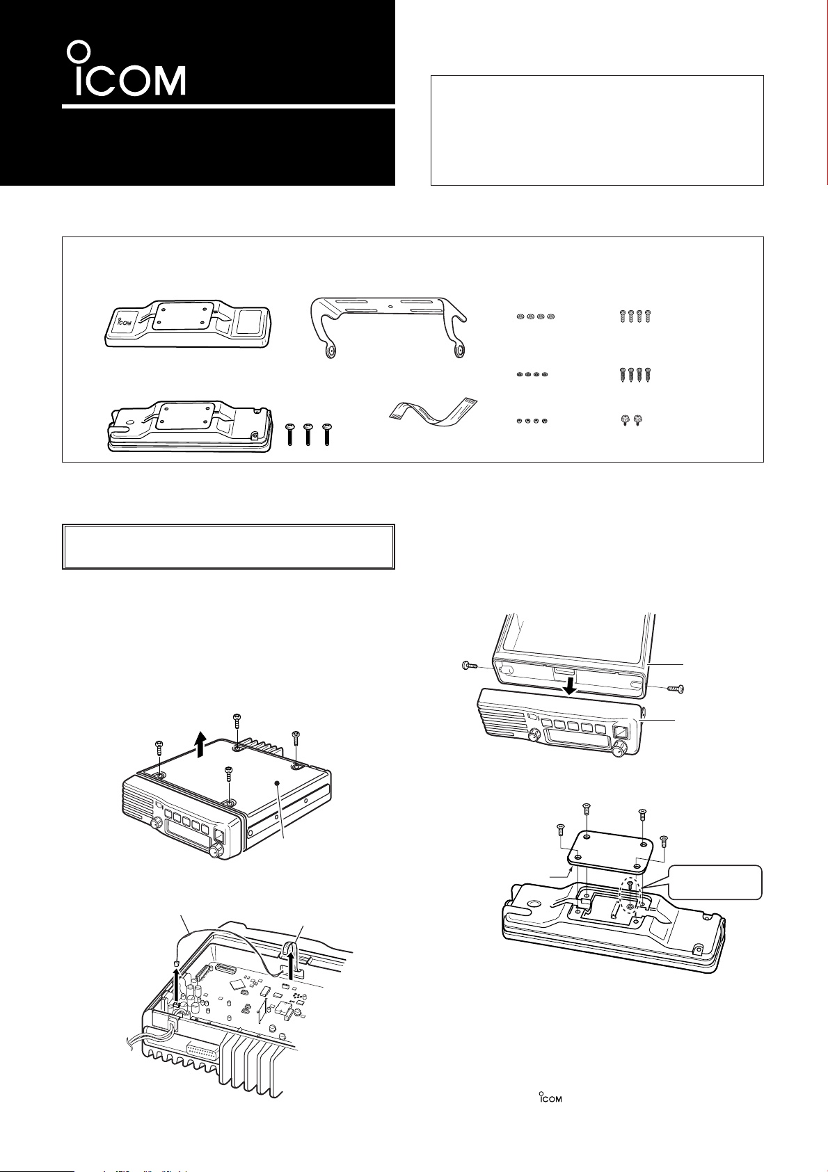
Rear plate
*This illustration shows
the description for the
front panel attachment.
Unscrew the circuit board screw.
Main unit
Front panel
Flat cable
Speaker cable*
*Depending on version
Bottom cover
Main unit attachment
Front panel attachment and bolts (M3×15)
Flat cable
Mounting bracket
Flat washers
(M5)
Spring washers
(M5)
Mounting screws
(M5×12)
Self-tapping screws
(M5×16)
Bracket screws
Nuts (M5)
SEPARATION KIT
RMK-2
■ Supplied accessories
Thank you for purchasing the RMK-2
SEPARATION KIT
The RMK-2 allows you to install the IC-F1700 series
transceiver front panel separately from the main unit
for added installation convenience and operation.
Use either the optional OPC-607, OPC-608 or OPC-
SEPARATION CABLE
609
with the RMK-2.
.
■ Separation
CAUTION! To avoid damage to the transceiver, turn the
power OFF before separating from the main unit.
The optional OPC-607 (3 m; 9.84 ft), OPC-608 (8 m; 26.3 ft) or
OPC-609*
stalling the transceiver front panel and main unit separately.
*For Europe version, only the OPC-609 is available.
q Turn the transceiver’s power OFF, then disconnect the DC
power cable.
w Unscrew the 4 bottom screws, then remove the bottom
cover from the transceiver in the direction of the arrow.
e Disconnect the flat cable and speaker cable* from the
main unit.
(1.9 m; 6.3 ft)
SEPARATION CABLE
is required for in-
r Unscrew the 2 side screws, then remove the front panel
from the transceiver main unit in the direction of the arrow.
t Unscrew the 4 screws, then remove the rear plates from
both the front panel and main unit attachments.
Icom, Icom Inc. and the logo are registered trademarks of Icom Incorporated (Japan) in the United States, the United Kingdom, Germany, France,
Spain, Russia and/or other countries.
☞ Continue to the back page.
Page 2
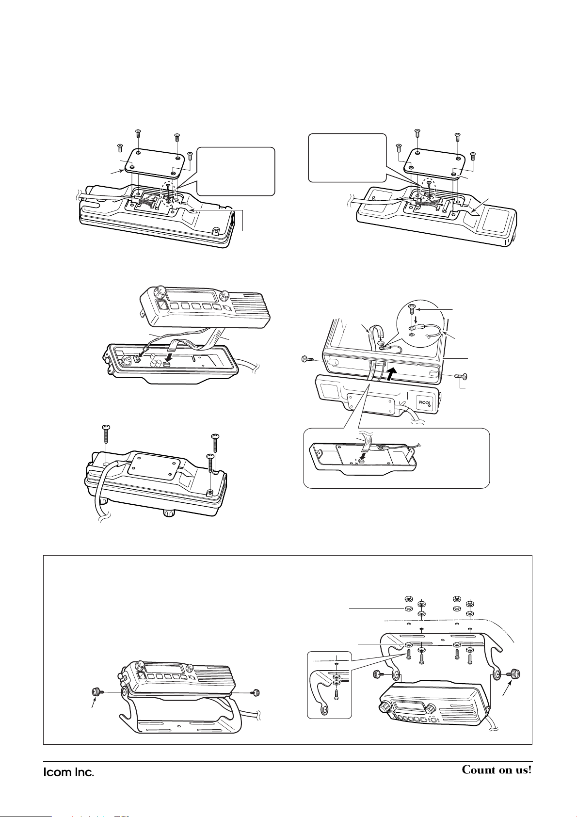
When using
self-tapping screws
Flat washer
Spring washer
Bracket
screw
Bracket screw
■ Attachment
Main unit
attachment*
Main unit
The removed screws
from the transceiver
Flat cable*
from the RMK-2
Use the attached screw
Main unit attachment
Flat cable*
to transceiver’s
main unit
OPC-607/
OPC-608/
OPC-609
Rear plate
Main unit attachment
Cable groove
Use the screw removed from the circuit board in step t
on the front page, to
connect the cable lug.
Flat cable
Speaker cable*
Front panel
Front panel attachment
*Depending on version
OPC-607/
OPC-608/
OPC-609
Rear plate
Front panel attachment
Cable groove
Use the screw
removed from the circuit board in step t
on the front page, to
connect the cable lug.
For the front panel attachment:
q Connect the optional OPC-607, OPC-608 or OPC-609 to
the front panel attachment as shown below.
After the cable connection, replace the removed rear plate
and the 4 screws.
• The optional cable can be inserted into either the left or right
grooves as desired on the back of the attachment.
For the main unit attachment:
r Connect the optional OPC-607, OPC-608 or OPC-609 to
the main unit attachment as shown below.
After the cable connection, replace the removed rear
plate.
• The optional cable can be inserted into either the left or right
grooves as desired on the back of the attachment.
w Connect the flat and speaker* cable as shown below.
• Ensure the flat cable is inserted correctly, and not upside down.
e Screw the 3 supplied bolts to attach the front panel and
the attachment.
t Connect the supplied flat cable* and ground cable (coming
from the RMK-2) as shown below.
Then use the 2 screws removed from the transceiver to
attach the main unit attachment* and the main unit.
*Ensure the flat cable and attachment are inserted/attached cor-
rectly, and not upside down.
y Replace the bottom cover and 4 screws removed earlier,
then re-connect the DC power cable.
■ Mounting
2 types of mounting styles are available— one is overhead
mounting, and other one is on-board mounting.
Mount the front panel and the attachment securely with the
4 supplied screws to a thick surface which can support more
than 1.5 kg. (Overhead mounting)
On-board mounting
1-1-32 Kamiminami, Hirano-ku, Osaka 547-0003, Japan
Overhead mounting
A-6420H-1EX-w Printed in Japan
© 2004–2005 Icom Inc.
 Loading...