

Page 1
INSTRUCTION MANUAL
FISH FINDER
MXF-5000
This device complies with Part 15 of the FCC Rules. Operation is subject to the following two conditions: (1) this device
may not cause harmful interference and (2) this device must
accept any interference received, including interference that
may cause undesired operation.
Page 2

FOREWORD
FCC INFORMATION
Thank you for purchasing Icom’s MXF-5000 FISH
FINDER.
The fish finder is designed for use with the Icom
MarineCommander™ system through the supplied
connection cable.
It has powerful transmission power and many other
advanced features can be used with the Icom
MarineCommander™ system.
After studying this manual, if you have any additional
questions regarding the operation of the fish finder,
contact your nearest authorized Icom Inc. dealer.
IMPORTANT
READ THIS INSTRUCTION MANUAL
CAREFULLY before attempting to operate the fi sh
fi nder.
SAVE THIS INSTRUCTION MANUAL. This
manual contains important safety and operating instructions for the MXF-5000.
• FOR CLASS A UNINTENTIONAL RADIATORS:
This equipment has been tested and found to comply
with the limits for a Class A digital device, pursuant to
part 15 of the FCC Rules. These limits are designed
to provide reasonable protection against harmful
interference when the equipment is operated in a
commercial environment. This equipment generates,
uses, and can radiate radio frequency energy and, if
not installed and used in accordance with the instruction manual, may cause harmful interference to radio
communications. Operation of this equipment in a
residential area is likely to cause harmful interference
in which case the user will be required to correct the
interference at his own expense.
CAUTION
finder, not expressly approved by Icom Inc., could
void your authority to operate this device under FCC
regulations.
: Changes or modifi cations to this fi sh
EXPLICIT DEFINITIONS
WORD DEFINITION
RDANGER
RWARNING
CAUTION
NOTE
Personal death, serious injury or an explosion may occur.
Personal injury, fi re hazard or electric
shock may occur.
Equipment damage may occur.
If disregarded, inconvenience only. No risk
of personal injury, fi re or electric shock.
Icom, Icom Inc. and the Icom logo are registered trademarks of
Icom Incorporated (Japan) in Japan, the United States, the United
Kingdom, Germany, France, Spain, Russia and/or other countries.
MarineCommander is a trademark of Icom Incorporated.
All other products or brands are registered trademarks or trademarks of their respective holders.
i
Page 3
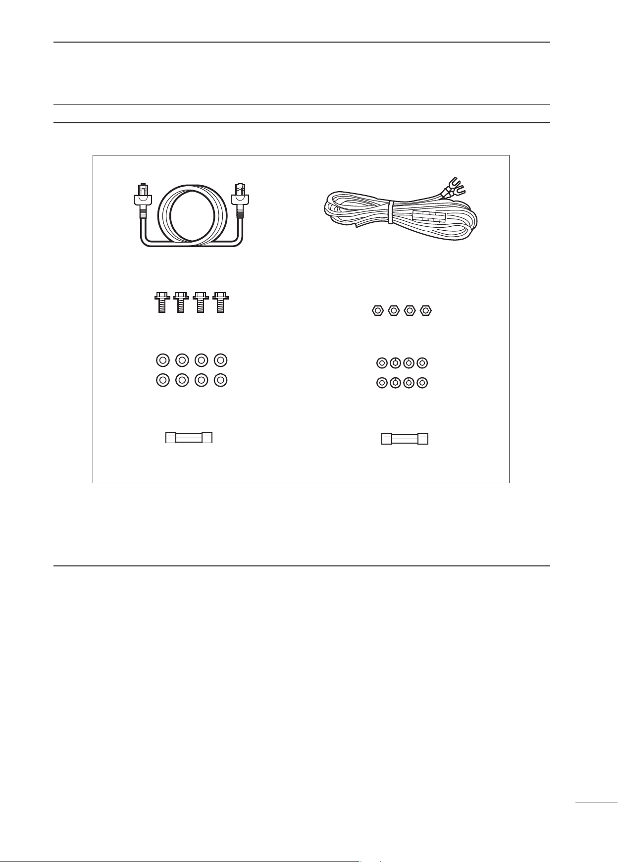
SUPPLIED ACCESSORIES
Connection cable (1.5 m (4.92 ft)) × 1 DC power cable (3 m (9.84 ft)) × 1
Bolts (M5×30 mm) × 4 Nuts (M5) × 4
Flat washers (M5) × 8 Spring washers (M5) × 8
Spare fuse (FGB 5 A) × 1
(For 12 V power source)
TABLE OF CONTENTS
FOREWORD ······························································i
IMPORTANT ······························································· i
EXPLICIT DEFINITIONS ············································ i
FCC INFORMATION ··················································i
SUPPLIED ACCESSORIES ······································ ii
TABLE OF CONTENTS ············································· ii
PRECAUTIONS ························································ iii
1 PANEL DESCRIPTION ·········································· 1
2 INSTALLATION AND CONNECTIONS ················· 2
■ Jumper setting
(When connecting an EX-3195 ONLY) ···············2
■ Connection ·························································3
■ Power source requirement ··································3
■ Ground connection ·············································3
■ Mounting ·····························································4
■ Installing the transducer ·····································4
Fuse (FGB 3 A) × 1
(For 24 V power source)
3 MAINTENANCE AND OPTIONS ···························7
■ Maintenance and inspection ·······························7
■ Periodic maintenance ·········································7
■ Fish fi nder maintenance ·····································7
■ Fuse replacement ···············································7
■ Options ·······························································7
4 SPECIFICATIONS ·················································· 8
ii
Page 4

PRECAUTIONS
RDANGER: A transducer MUST BE installed
by a shipbuilder or a qualifi ed installer.
Improper installation could cause water leaks and
other severe damage.
RWARNING: NEVER let metal, wire or other
objects touch any internal part or terminals of the fi sh
fi nder.
This may result in an electric shock.
RWARNING: NEVER apply AC voltage to the
DC input terminals of the fi sh fi nder.
This may pose a fire hazard, result in an electric
shock or damage the fi sh fi nder.
RWARNING: NEVER apply more than 32 V
DC to the DC input terminal of the fi sh fi nder.
This may pose a fi re hazard or damage the fi sh fi nder.
R WARNING: Immediately turn the Icom
MarineCommander™ system and fish finder power
OFF, and remove the power cable if it emits an
abnormal odor, sound or smoke. Contact your Icom
dealer or distributor for advice.
RWARNING: NEVER touch the fi sh fi nder with
wet hands.
This may result in an electric shock or damage the
fi sh fi nder.
RWARNING: NEVER open the bottom cover
of the fi sh fi nder by yourself. This should only be done
by qualifi ed equipment installers.
There are no user adjustment points. Opening the
case may expose you to electric shock and incorrect
reassembly may cause a fi re hazard.
DO NOT place the fish finder in excessively dusty
environments.
DO NOT place the fish finder near heating
equipment or in direct sunlight or where hot or cold air
blows directly onto it.
DO NOT use or place the fish finder in areas with
temperature below –20˚C (–4˚F) or above +60˚C
(+140˚F).
DO NOT use chemical agents such as benzine
or alcohol when cleaning the fish finder, as they can
damage the fi sh fi nder’s surfaces.
To clean the equipment, wipe it using a soft cloth
damped with a water-diluted detergent.
DO NOT place the fish finder in areas that will
block air passage or put anything around the fish
fi nder. This will obstruct heat dissipation.
KEEP the fi sh fi nder out of the reach of children.
KEEP the fish finder away from heavy rain, and
never immerse it in the water.
The fish finder meets IPX4 requirements for splash
resistance when the transducer is attached to one
connector, and the connector cap is installed on the
other connector.
However, if it is dropped, splash resistance cannot be
guaranteed because of possible damage to the case
or the waterproof seals.
RWARNING: NEVER modify or attempt to
repair the equipment by yourself.
ONLY qualified persons are allowed to modify or
repair the equipment.
CAUTION! NEVER connect the fi sh fi nder to a
DC power source using reverse polarity.
This will damage the fi sh fi nder.
CAUTION! NEVER remove the fuse holders
from the DC power cable.
This will damage the fi sh fi nder.
CAUTION! KEEP the fi sh fi nder at least 1 meter
(3.28 ft) away from your vessel’s magnetic navigation
compass.
iii
Page 5

This terminal is not used.
qw r
q DC POWER INPUT TERMINALS (p. 3)
Connect the 12 V/24 V DC power supply through
the supplied DC power cable.
w GROUND TERMINALS (p. 3)
Connect these terminals to ground to prevent
electrical shocks.
e MarineCommander™ CONNECTOR (p. 3)
Connect this connector to the Icom MarineCom-
mander™.
r TRANSDUCER1/2 CONNECTORS (pgs. 3–6, 8)
Connect the transducer to either connector.
NEVER CONNECT 2 transducers to these
connectors at the same time.
PANEL DESCRIPTION
e
1
1
2
3
4
5
6
7
8
9
10
11
12
13
14
15
16
17
18
1
19
20
21
Page 6

2
INSTALLATION AND CONNECTIONS
For qualifi ed equipment installers ONLY
■ Jumper setting (When connecting an EX-3195 ONLY)
DO NOT open the bottom cover of the fish finder
unless connecting an EX-3195.
When connecting an EX-3195, move the jumper
(MAIN unit; J15) to the 1 kW position as follows.
CAUTION: Before changing the jumper setting,
make sure disconnecting the fi sh fi nder’s DC power
cable from the battery.
q Remove the 9 screws from the bottom cover and
remove it.
Remove the 9 screws
w Move the jumper to the 1 kW position.
600 W jumper position
(Default)
1 kW jumper position
MAIN unit
J15
e Return the bottom cover to the original position, and
then reinstall the 9 screws.
2
Page 7

■ Connection
CAUTION: Before connecting, make sure
disconnecting the fi sh fi nder’s DC power cable from
the battery.
EX-3193
NEVER connect anything
other than Icom optional
transducers.
•
(
600 W Tramsom type,
built-in boat speed and
temperature sensors)
INSTALLATION AND CONNECTIONS
EX-3194 EX-3195
••
(
600 W Thru Hull type,
built-in boat speed and
temperature sensors)
(
1 kW Thru Hull type,
built-in temperature
sensor)
2
1
2
Detach the terminal guard first.
Terminal guard
NOTE: Use the terminals as
shown below for the cable connections.
Crimp
Solder
12 V/24 V
battery
■ Power source requirement
CAUTION: Before connecting the DC power cable,
check the following important items.
Make sure:
• Output voltage of the power source is 12/24 V DC.
• DC power cable polarity is correct.
Red : Positive + terminal
Black : Negative _ terminal
• Fuse rating of the DC power cable is correct. (The
5 A fuse is pre-installed.)
3 A : For 24 V power source
5 A : For 12 V power source
Optional transducers
Ground
MXF-5000
Turn the power OFF.
MarineCommander™
MXP-5000
DC IN
12V/24V
NC
GND
KEEP the terminal
guard attached after
connecting cables.
■ Ground connection
To prevent electrical shocks and other problems,
ground the fish finder unit through the [GND]
terminals. For best results, connect a heavy gauge
wire or strap to the nearest grounding point on the
boat. The distance between the [GND] terminals and
the ground point should be as short as possible.
3
4
5
6
7
8
9
10
11
12
13
14
15
16
17
18
19
20
3
21
Page 8

2
INSTALLATION AND CONNECTIONS
■ Mounting
First, drill four φ5.5–6 mm (7⁄32–1⁄4″) holes to mount
the fi sh fi nder using the units base as a pattern.
Mount the fish finder securely with the four supplied
bolts (M5×30 mm) to a flat surface which supports
more than approx. 5 kg (11 lb).
CAUTION: KEEP the fi sh fi nder at least 1 meter
(3.28 ft) away from your vessel’s magnetic
navigation compass.
Bolt
First, drill four φ5.5–6 mm (
holes to mount the MXF-5000.
7
⁄32–1⁄
)
″
4
Nut
■ Installing the transducer
D Optional transducers and accessories
Spring washer
Flat washer
Flat washer
Spring washer
Various types of transducers and boat speed/water
temperature sensors are available as options, to suit
your application.
MODEL NAME DETAILS
EX-3193
EX-3194
EX-3195
OPC-1929 Approx. 6 m (19.69 ft) extension cable for transducer
4
Transom type transducer
(600 W, 50 kHz and 200 kHz frequencies, built-in boat speed and temperature sensors)
Thru Hull type transducer
(600 W, 50 kHz and 200 kHz frequencies, built-in boat speed and temperature sensors)
Thru Hull type transducer
(1 kW, 50 kHz and 200 kHz frequencies, built-in temperature sensor)
Page 9

D Installation position
RDANGER: A transducer MUST BE installed by a
shipbuilder or a qualifi ed installer.
Improper installation could cause water leaks and
other severe damage.
RWARNING: BE SURE the fi sh fi nder’s power is
OFF* whenever you are working with the transducer.
* The fi sh fi nder’s power automatically turns OFF
approx. 30 sec. after the display unit’s power is
turned OFF. When 2 display units are connected to
the MarineCommander™, all units’ power must be
turned OFF.
INSTALLATION AND CONNECTIONS
The performance of the fish finder greatly
depends on the installation position of the transducer. See transducer’s instruction manual for
details.
Transducers are mainly divided into two types: the
transom type and the Thru Hull type.
Install the transducer in the following area.
q Area where the possibility of on-screen voids due
to air bubbles or water turbulence is minimized;
w Area that resists being exposed to noises from the
engine;
e Area where the transducer is kept horizontal even
if the boat runs at high speed;
( The optimum installation position of the transduc-
er is said to be at a distance of a half or one-third
of the boat length from the stern for low-speed
small boats, and close to the stern for high-speed
boats.)
2
1
2
3
4
• Installation example of the EX-3193 (600 W Transom type, built-in boat speed and temperature sensors)
To the TRANSDUCER 1 or TRANSDUCER 2
terminal of the MXF-5000
Bottom of the boat
• Installation example of the EX-3194 (600 W Thru Hull type, built-in boat speed and temperature sensors)
To the TRANSDUCER 1 or TRANSDUCER 2
terminal of the MXF-5000
5
6
7
8
9
10
11
12
13
14
15
16
Bottom of the boat
17
18
19
20
21
5
Page 10

2
INSTALLATION AND CONNECTIONS
D Optional transducer’s dimensions (approx.)
• EX-3193 (600 W Transom type, built-in boat speed and temperature sensors)
155 mm
(6.12″)
100 mm
70 mm
(2.76″)
• EX-3194 (600 W Thru Hull type, built-in boat speed and temperature sensors)
(3.92″)
2-12″ UN
80 mm
(3.15″)
64 mm
(2.50″)
threads
φ51 mm
(2.00″)
• EX-3195 (1 kW Thru Hull type, built-in temperature sensor)
178 mm
37 mm
(1.46″)
(4.17″)
106 mm
(7.01″)
(6.00″)
152 mm
53 mm
(2.09″)
140 mm
(5.50″)
142 mm
(5.59″)
28 mm
(1.10″)
M30-2
threads
6
Page 11

MAINTENANCE AND OPTIONS
3
■ Maintenance and inspection
RWARNING: BE SURE the fi sh fi nder’s power is
OFF before performing any maintenance.
Continued, reliable operation of the fish finder
depends on how you care for your equipment.
The simple maintenance tips that follow can help you
save time and money, and avoid premature equipment failures.
■ Periodic maintenance
q Keep the equipment as clean as possible.
• Use a soft cloth to remove dirt, dust and water.
w Check all hardware for loose screws, bolts, etc.
e Check cables and terminal connections.
■ Fish fi nder maintenance
This fi sh fi nder is designed to be easy for the operator to maintain.
Proper maintenance allows to the system to be kept
in a optimum state and reduces the possibility of malfunctions.
As high voltages is used in the system, be sure to
read the PRECAUTIONS (p. iii) before commencing
maintenance work.
• To remove dirt from the MXF-5000’s cover, wipe it
using a soft cloth dampened with a water-diluted
detergent.
• To clean the MXF-5000, wipe it using a soft cloth
dampened with an anti-static agent or water.
• Check cable connections and the GND terminal for
contamination and looseness.
Also check cables for wear.
• Check the transducer surface, cables and connectors for rust or adhesion of marine organisms such
as algae.
To clean the transducer surface, wipe it using a soft
brush dampened with a detergent.
■ Options
• OPC-1895 CONNECTION CABLE
Allows you to connect the Icom MarineCommander™
system. (20 m: 65.6 ft)
• EX-3193 TRANSDUCER
600 W Transom type, built-in boat speed and tem-
perature sensors
• EX-3194 TRANSDUCER
600 W Thru Hull type, built-in boat speed and tem-
perature sensors
• EX-3195 TRANSDUCER
1 kW Thru Hull type, built-in temperature sensor
• OPC-1929 TRANSDUCER CABLE
6 m (19.69 ft) extension cable for transducer
Approved Icom optional equipment is designed for
optimal performance when used with an Icom fish
fi nder.
Icom is not responsible for the destruction or
damage to an Icom fish finder in the event the
Icom fish finder is used with equipment that is not
manufactured or approved by Icom.
1
2
3
4
5
6
7
8
9
10
11
12
13
14
■ Fuse replacement
One fuse is installed in the supplied DC power cable.
If the fuse blows, fi nd the source of the problem and
have it repaired. Then replace the blown fuse with
a new, properly rated one (FGB 5 A for 12 V power
source, FGB 3 A for 24 V power source) as shown
below.
15
16
17
18
19
20
21
7
Page 12

4
SPECIFICATIONS
■ MXF-5000
• Power supply : 10.8 V to 31.2 V DC
• Current drain : Less than 0.6 A (water depth range: 40 m/output power: 600 W at 12 V DC)
Less than 1.0 A (water depth range: 40 m/output power: 1 kW at 12 V DC)
• Output power : 600 W/1 kW
• Transmission frequency : 50 kHz ±1 kHz
200 kHz ±1 kHz
• Usable temperature range : –20°C to +60°C; –4°F to +140°F
• Dimensions : 250(W) × 67(H) × 200(D) mm; 927⁄32(W) × 25⁄8(H) × 77⁄8(D) in
(Projections not included)
• Weight (approx.) : 2.18 kg; 4.8 lb
■ EX-3193 ( Option; 600 W Transom type, built-in boat speed and
temperature sensors)
• Operating frequency : 50 kHz, 200 kHz
• Cone angle : 50 kHz: 45°, 200 kHz: 11°
• Vessel speed sensor : 18,000 p/nm*
• Weight (approx.) : 0.5 kg; 1.1 lb
■ EX-3194 ( Option; 600 W Thru Hull type, built-in boat speed and
temperature sensors)
• Operating frequency : 50 kHz, 200 kHz
• Cone angle : 50 kHz: 45°, 200 kHz: 11°
• Vessel speed sensor : 19,000 p/nm* (with fairing)
21,500 p/nm* (without fairing)
• Weight (approx.) : 2.5 kg; 5.5 lb
■ EX-3195 ( Option; 1 kW Thru Hull type, built-in temperature sensor)
• Operating frequency : 50 kHz, 200 kHz
• Cone angle : 50 kHz: 15° × 21°, 200 kHz: 3° × 5°
• Weight (approx.) : 3.6 kg; 7.94 lb
*pulses per nautical mile
All stated specifi cations are subject to change without notice or obligation.
8
Page 13

MEMO
1
2
3
4
5
6
7
8
9
10
11
12
13
14
15
16
9
17
18
19
20
21
Page 14

MEMO
10
Page 15

MEMO
1
2
3
4
5
6
7
8
9
10
11
12
13
14
15
16
11
17
18
19
20
21
Page 16

A-6753H-1EX-q
Printed in Japan
© 2009 Icom Inc.
1-1-32 Kamiminami, Hirano-ku, Osaka 547-0003, Japan
 Loading...