

Page 1

INSTRUCTION MANUAL
MARINE PLOTTER
MXP-5000
DISPLAY UNIT
MXD-5000
This device complies with Part 15 of the FCC Rules. Operation is subject to the following two conditions: (1) this device
may not cause harmful interference and (2) this device must
accept any interference received, including interference that
may cause undesired operation.
Page 2
FOREWORD
SUPPLIED ACCESSORIES
Thank you for purchasing Icom’s MXP-5000 m a r i n e
p l o t t e r and MXD-5000 d i s p l a y u n i t .
IMPORTANT
READ THIS INSTRUCTI ON MANUAL
CAREFULLY before attempting to operate the Ma-
rine Commander.
SAVE THIS INSTRUCTION MANUAL. This
manual contains important safety and operating instructions for the MXP-5000 and MXD-5000.
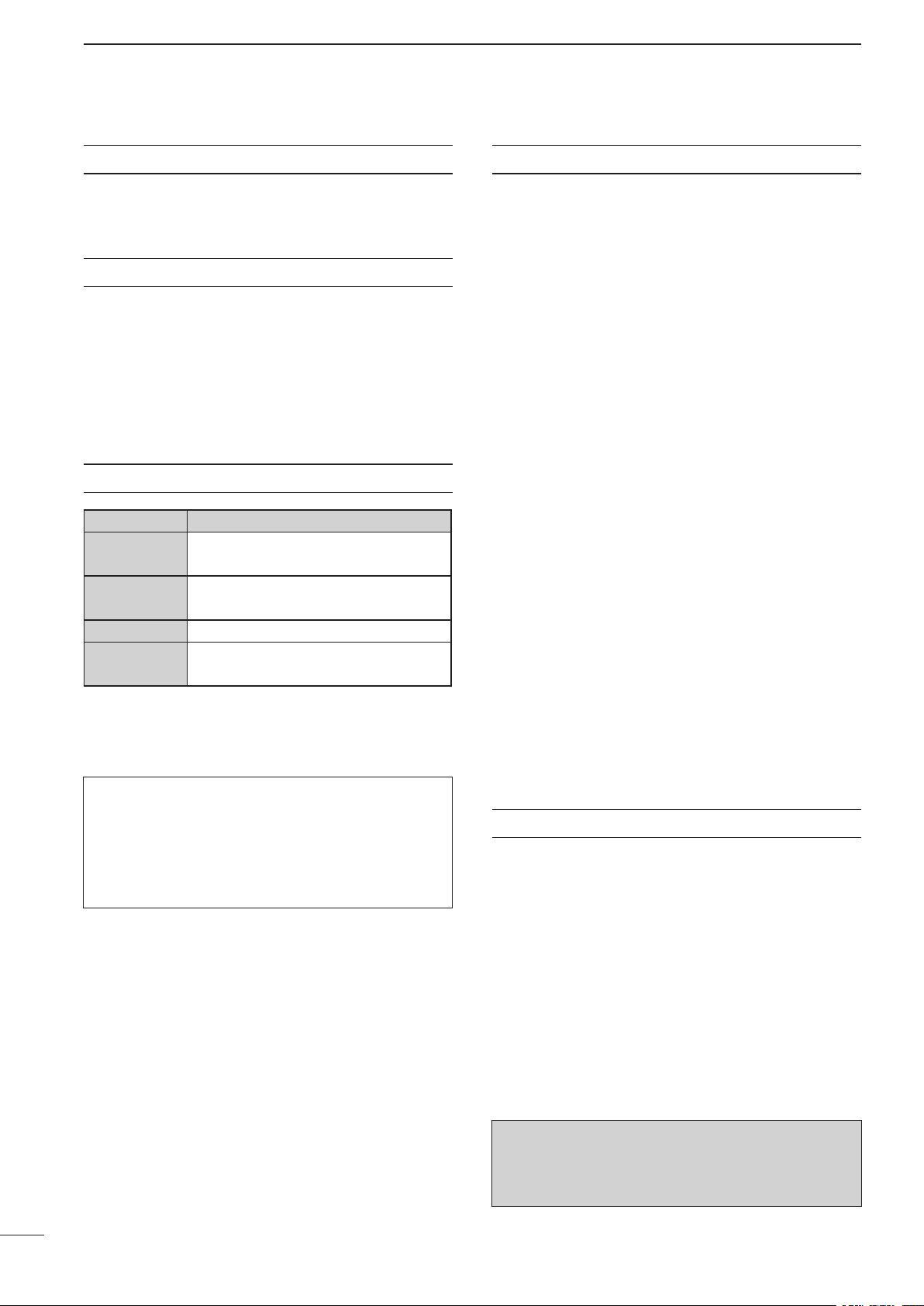
EXPLICIT DEFINITIONS
WORD
RDANGER!
RWARNING!
CAUTION
NOTE
Personal death, serious injury or an explosion may occur.
Personal injury, fire hazard or electric
shock may occur.
Equipment damage may occur.
If disregarded, inconvenience only. No risk
of personal injury, fire or electric shock.
DEFINITION
Qty.
MXP-5000 (MAIN UNIT)
• DC power cable .......................................................... 1
• Ferrite EMI Filter ......................................................... 1
• OPC-1897 (Connection cable: D-SUB 25 pin) ............ 1
• Spring washers (M5) ................................................ 12
• Flat washers (M5) .................................................... 12
• Nuts (M5) ................................................................... 6
• Bolts (M5×30 mm) ...................................................... 6
• Fuse (FGB 7.5 A for a 24 V power source) ................ 1
• Spare fuse (FGB 15 A for a 12 V power source) ........ 1
MXD-5000 (DISPLAY UNIT)
• Front cover ................................................................. 1
• Mounting bracket kit .............................................. 1 set
- Mounting bracket ...................................................... 1
- Knob bolts ................................................................ 2
- Hex head bolts (M6×30 mm) .................................... 5
- Flat washers (M6) .................................................. 10
- Spring washers (M6) .............................................. 10
- Nuts (M6) ................................................................. 5
• Mounting bolt (M6×35 mm) ........................................ 4
• Flat washers for wall mounting (M6) .......................... 4
• Spring washers for wall mounting (M6) ...................... 4
• Nuts for wall mounting (M6) ....................................... 4
• Cap ............................................................................. 4
EX-3187 (DISPLAY EXTENSION UNIT)
• Self-tapping screw (A0 4×20 mm) .............................. 2
• Flat washers (M4) ...................................................... 2
• Spring washers (M4) .................................................. 2
For Users in California (U.S.A.)
The MXP-5000 uses a Coin Lithium Battery which
contains Perchlorate Material—special handling may
apply.
See http://www.dtsc.ca.gov/hazardouswaste/perchlorate
Icom, Icom Inc. and the Icom logo are registered trademarks of
Icom Incorporated (Japan) in Japan, the United States, the United
Kingdom, Germany, France, Spain, Russia and/or other countries.
MarineCommander and MarineCommander logo are trademarks of
Icom Incorporated.
C-MAP is a trademark of Jeppesen.
All other products or brands are registered trademarks or trademarks of their respective holders.
FCC INFORMATION
• FOR CLASS A UNINTENTIONAL RADIATORS:
This equipment has been tested and found to comply
with the limits for a Class A digital device, pursuant to
part 15 of the FCC Rules. These limits are designed
to provide reasonable protection against harmful
interference when the equipment is operated in a
commercial environment. This equipment generates,
uses, and can radiate radio frequency energy and, if
not installed and used in accordance with the instruction manual, may cause harmful interference to radio
communications. Operation of this equipment in a
residential area is likely to cause harmful interference
in which case the user will be required to correct the
interference at his own expense.
CAUTION: C hanges o r modifications to these
equipment, not expressly approved by Icom Inc.,
could void your authority to operate these equipment
under FCC regulations.
i
Page 3

TABLE OF CONTENTS
FOREWORD ······························································ i
IMPORTANT ······························································· i
EXPLICIT DEFINITIONS ············································ i
SUPPLIED ACCESSORIES ······································· i
FCC INFORMATION ··················································i
TABLE OF CONTENTS ············································· ii
PRECAUTIONS ························································ iii
1 PANEL DESCRIPTION ······································ 1–5
■ Main unit (MXP-5000) ·········································1
■ Display unit (MXD-5000) ····································2
2 INSTALLATION AND CONNECTIONS ···········6–11
■ Connection ·························································6
■ Mounting the Main unit ·······································7
■ Power source requirement ··································7
■ Ground connection ·············································7
■ Installing the Display unit ····································8
■ Front cover attachment ·····································10
■ Bolt cap attachment ··········································10
■ Removing or connecting the EX-3187’s cable ··11
1
2
3
4
5
3 MAINTENANCE AND OPTIONS ·························12
■ Periodic maintenance ·······································12
■ Fuse replacement ·············································12
■ Options ·····························································12
4 SPECIFICATIONS ················································13
5 CONNECTOR INFORMATION ····························14
6
7
8
9
10
11
12
13
14
15
16
17
ii
18
19
20
21
Page 4

PRECAUTIONS
Common (MXP-5000/MXD-5000/EX-3187):
R WARNING! NEVER let metal, wire or other ob-
jects touch any internal part or terminals of these units.
This may result in an electric shock.
R WARNING! NEVER touch these units with wet
hands. This may result in an electric shock or damage
these units.
DO NOT place these units near heating equipment
or in direct sunlight or where hot or cold air blows directly onto them.
DO NOT use or place these units in areas with
temperature below –20˚C (–4˚F) or above +60˚C
(+140˚F).
DO NOT place these units in areas that will block air
passage or put anything around these units. This will
obstruct heat dissipation.
DO NOT
cohol to clean these units, as they will damage these
units’ surfaces.
use harsh solvent such as benzine or al-
KEEP these units out of the reach of children.
For MXP-5000 (Main unit):
R WARNING! NEVER apply AC voltage to the DC
input terminals of the Main unit. This may pose a fire
hazard, result in an electric shock or damage the Main
unit.
R WARNING! NEVER apply more than 32 V DC
to the DC input terminals of the Main unit or use reverse polarity. This may pose a fire hazard or damage
the Main unit.
KEEP the Main unit away from heavy rain, and never
immerse it in the water.
The Main unit meets IPX4 requirements for splash
resistance when the supplied connection cables are
connected, and the connector cap is installed on the
other connector.
However, if it is dropped, splash resistance cannot be
guaranteed because of possible damage to the case
or the waterproof seals.
For MXD-5000 (Display unit):
DO NOT place the Display unit in excessively dusty
environments.
BE CAREFUL!
ments for waterproof protection
and the access cover on the Front panel is closed.
However, if the Display unit has been dropped, waterproof protection cannot be guaranteed because of possible damage to the Display unit’s case or the waterproof seal.
The Display unit meets IPX7 require-
when the rear cover,
For EX-3187 (Display extension unit):
KEEP the Display extension unit away from heavy
rain, and never immerse it in the water.
The Display extension unit meets IPX4 requirements
for splash resistance when the connection cables are
connected.
However, if it is dropped, splash resistance cannot be
guaranteed because of possible damage to the case
or the waterproof seals.
R WARNING! NEVER cut the DC power cable
between the DC plug and fuse holder. If an incorrect
connection is made after cutting, the Main unit may be
damaged.
R WARNING! NEVER open the bottom cover of
the Main unit. There are no user adjustment points.
This may result in an electric shock and incorrect reassembly may cause a fire hazard.
DO NOT place the Main unit in excessively dusty en-
vironments.
iii
Page 5
MAIN
DATA IN/OUT
EXT-DISPLAY
NMEA2000
BLACK BOX
12 34
HEADING GPS
DC IN
DISPLAY
SUB
VIDEO IN
1234
qr ew
!0
i oy u
t
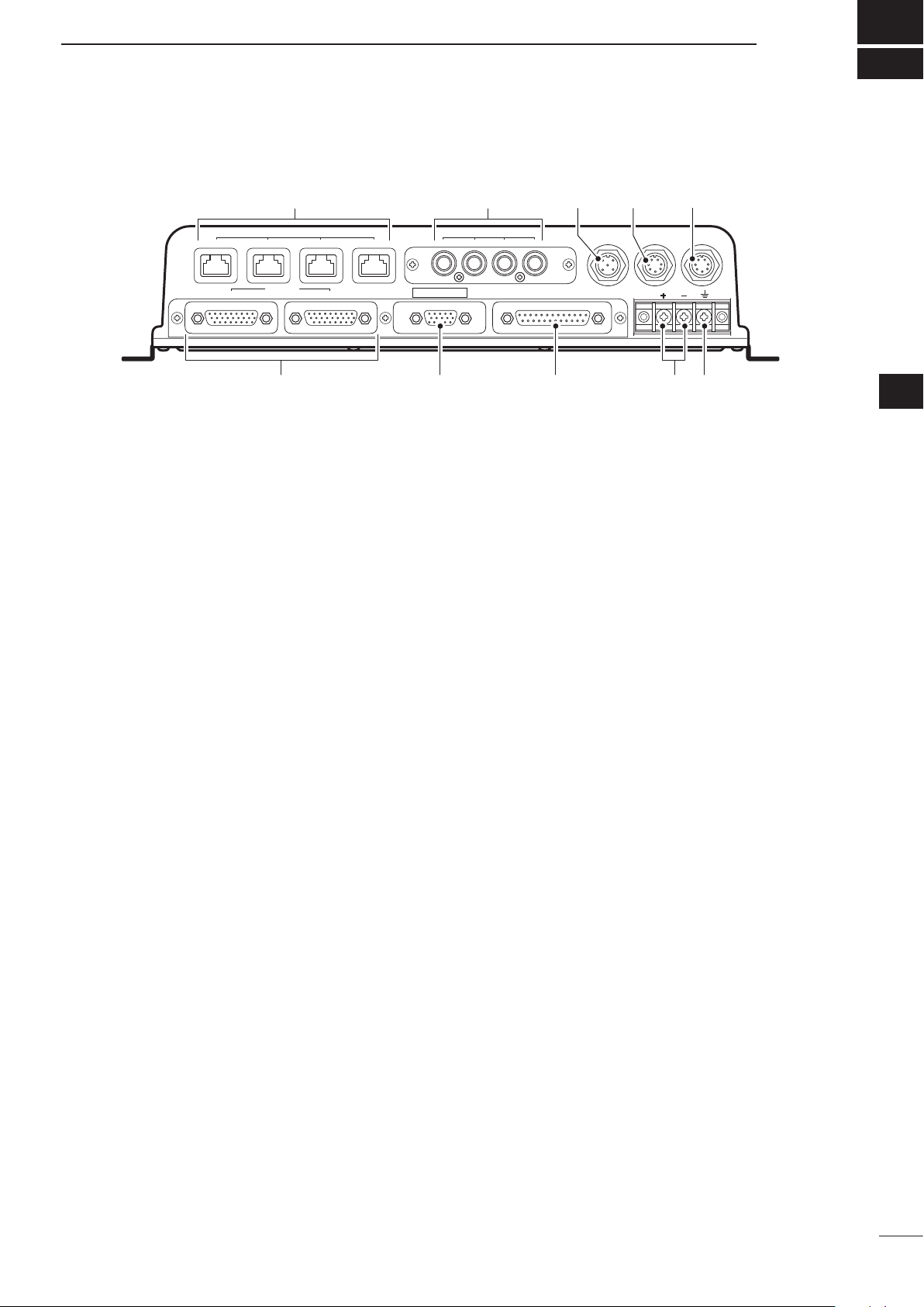
■ MXP-5000 (Main unit)
PANEL DESCRIPTION
1
1
q GROUND TERMINAL
Connect a ground wire to ground to prevent electri-
cal shocks.
w DC POWER INPUT TERMINALS
Connect the 12 V/24 V DC power source through
the DC power cable.
e DATA IN/OUT CONNECTOR [DATA IN/OUT]
Connect an Icom AIS Transponder, Marine VHF
transceiver or navigation equipment.
See page 14 for the [DATA IN/OUT] connector infor-
mation details.
r EXTERNAL DISPLAY CONNECTOR
[EXT-DISPLAY]
Connect an external monitor or a PC monitor with a
D-sub 15-pin connector (DE-15).
The monitor shows the same display as the MAIN
display.
• The monitor resolution of 800 × 600 pixels or higher is
required.
• The monitor shows the same display as the MAIN dis-
play.
t MAIN DISPLAY UNIT CONNECTOR [MAIN]
SUB DISPLAY UNIT CONNECTOR [SUB]
Connect the MXD-5000 Display unit. Two display
units can be connected.
u VIDEO IN CONNECTORS
Four video inputs, such as onboard cameras, can
be connected. An RCA type connector is used for
these connectors. NTSC or PAL format is compatible.
i NMEA2000 CONNECTOR [NMEA2000]
Connect NMEA 2000 sensors to monitor, the en-
gine, fuel, engine temperature, wind, GPS, Compass and STW.
o HEADING CONNECTOR [HEADING]
Connect a heading sensor.
This connector is the same as port 2 of the [DATA
IN/OUT] connector.
See page 14 for the [DATA IN/OUT] connector infor-
mation details.
!0 GPS RECEIVER CONNECTOR [GPS]
Connect the MXG-5000 GPS receiver.
2
3
4
5
6
7
8
9
10
11
12
13
14
15
y BLACK BOX CONNECTORS
• Connector 1 to 3
Connect a black box unit such as, an MXR-
5000R/T Radar unit, an MXF-5000 Fish nder unit
or another MXP-5000 Main unit.
• Connector 4
Not used.
If you connect an MXR-5000R/T or MXF-5000 to
this connector, these units will not operate.
16
17
18
19
20
21
1
Page 6
1
P
U
S
H
T
O
E
N
T
E
R
MENU
WPT
FOCUS
LAYOUT
MOB
CLEAR
SUB
BRILL
RANGE
q
w
e
r
t
y
u
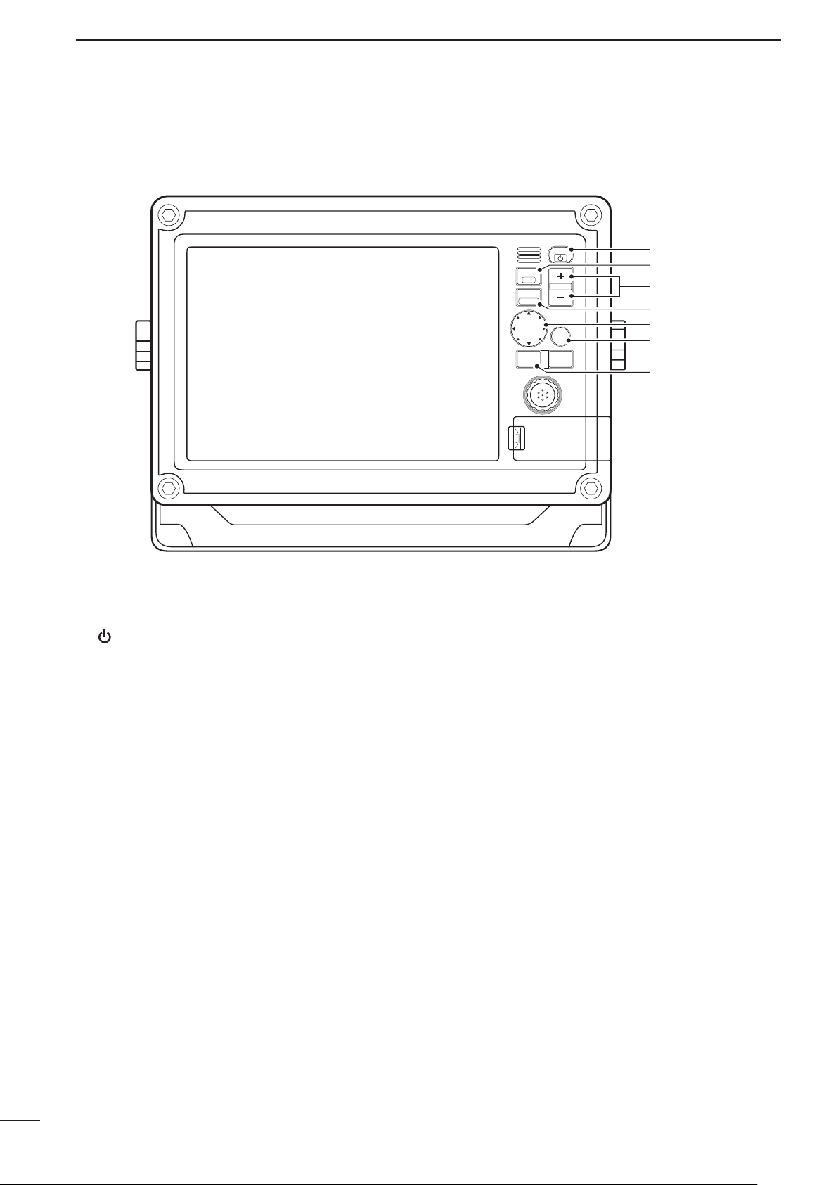
PANEL DESCRIPTION
■ MXD-5000 (Display unit)
D Front panel
q
POWER/DISPLAY BRILLIANCE SWITCH
[ /BRILL]
• While the MarineCommander’s power is OFF
Push to turn ON the MarineCommander’s power.
• While the MarineCommander’s power is ON
➥ Push to open Quick Menu 1.
• The Quick Menu 1 includes the Display Brilliance,
Radar TX setting, Panel Brilliant and Color Palette.
• Push two or more times to increase or decrease
the display brilliance level.
➥ Hold down for 3 seconds to turn OFF the Mari-
neCommander’s power.
w WAYPOINT/MAN OVERBOARD SWITCH
[WPT/MOB]
➥ Push to open the Waypoint screen.
• The Waypoint window appears.
➥ When a crew member falls overboard, hold down
for 3 seconds to mark the man overboard point
on the screen.
• The MOB readout shows the bearing and distance to
the MOB point. (Position and bearing data are necessary.)
• Hold down [MOB] for 3 seconds to cancel the function.
e RANGE UP/ DOWN SWITCHES [+]/[–]
Push [+] or [–] to set a suitable screen range.
r FOCUS/DISPLAY LAYOUT SWITCH
[FOCUS/LAYOUT]
➥ Push to change the active screen.
• An orange border indicates the active screen.
➥ Hold down for 3 seconds to open the display se-
lection screen.
t UP, DOWN, LEFT, RIGHT KEYS [Ù] [Ú] [Ω] [≈]
➥ Push arrow [Ù], [Ú], [Ω] or [≈] to move the cur-
sor up, down, left or right on the active screen.
Push the dot to move at an angle.
➥ In the Menu screen, push [Ù] or [Ú] to select an
item.
➥ In Quick Menu 1 or Quick Menu 2, push [Ω] or
[≈] to select an item.
➥ In Quick Menu 1 or Quick Menu 2, push [Ù] or
[Ú] to select an option or adjust a level.
y SUB MENU SWITCH [SUB]
On the Menu screen, push to enter the Sub Menu.
u MENU SWITCH [MENU]
Push to select the Menu screen.
2
Page 7

P
U
S
H
T
O
E
N
T
E
R
MENU
WPT
FOCUS
LAYOUT
MOB
CLEAR
SUB
BRILL
RANGE
i
o
!0
!1
!2
D Front panel
PANEL DESCRIPTION
1
1
2
3
4
i CLEAR SWITCH [CLEAR]
Push to cancel the current function.
While opening the Menu screen, push to cancel
and return to the upper menu, or cancel the Menu
screen.
o SELECTION DIAL [DIAL]
➥ In the Menu screen, rotate to select a menu item
or option.
➥ In Quick Menu 1 or Quick Menu 2, rotate to se-
lect an option or adjust a level.
On the Plotter screen
➥ Rotate to set the heading position.
!0 ENTER SWITCH
➥ In the Menu screen, push to access the selected
menu or function.
➥ Push to access Quick Menu 2.
On the Plotter screen
• Quick Menu 2 includes the Center Ship and Perspec-
tive Angle functions.
On the Radar screen
• Quick Menu 2 includes the GAIN, SEA, RAIN, Radar
TX menu and Heading line OFF functions.
On the Sounder screen
• Quick Menu 2 includes the GAIN 50kHz, GAIN
200kHz, STC 50kHz and STC 200kHz control functions.
!1 SD CARD PORT
Insert an SD Card which contains C-MAP MAX
chart* by JEPPESEN.
* Chart data is not supplied by Icom.
• An unmount operation should be performed before
removing the SD Card. If you do not unmount the SD
Card, the MarineCommander
t m
will stop operating.
!2 USB MEMORY PORT
Connect a USB memory stick.
• An unmount operation should be performed before removing the USB memory stick. If you do not unmount
the USB memory stick, the MarineCommander
stop operating.
t m
will
5
6
7
8
9
10
11
12
13
14
15
16
17
18
19
20
21
3
Page 8

1
ew
q
tr
y
PANEL DESCRIPTION
D Display
q DATA-BAR
Shows various information on palettes 1 to 4.
• A total of 20 options are selectable.
The Selectable options are Date/Time, Position, COG/
SOG, COG, SOG, Heading/STW, Heading, STW, Depth/
Temp., Depth, Temp., Trip Log, Waypoint, XTE, ETA/
TTG, ETA, TTG, Cursor, Startus and Wind.
w PALETTE1
Shows various information.
(Default: Position)
Shows the current position data* in latitude/longi-
tude.
* Depending on the presetting, Loran-C Time differences
are displayed instead of the position data.
• When the position data is invalid, the position data is
shown in red for 1 minute. After 1 minute has passed,
“–––” (invalid data) will appear.
e PALETTE2
Shows various information.
(Default: COG)
Shows your vessel’s course over ground.
• “T” shows true north bearing, and “M” shows magnetic
north bearing.
r PALETTE3
Shows various information.
(Default: SOG)
Shows your vessel’s speed over ground.
If no speed data is found, “–––” will appear.
t PALETTE4
Shows various information.
(Default: Depth)
Shows the current depth of the sea bottom, under
the vessel.
When a companion Icom fish finder is not connected
to the main unit, or the sea bottom is not detected,
“–––” (invalid data) will appear.
y CROSS HAIR CURSOR
Appears and moves on the screen when [Ù], [Ú],
[Ω] or [≈] is pushed.
4
Page 9

uoi!1!4 !3 !2 !0
D Display
PANEL DESCRIPTION
1
1
2
3
4
u STATUS-BAR
➥ Shows the status data.
• A total of 19 options are selectable.
The selectable options are Date/Time, Position, COG/
SOG, COG, SOG, Heading/STW, Heading, STW,
Depth/Temp., Depth, Temp., Trip Log, Waypoint, XTE,
ETA/TTG, ETA, TTG, Wind and Cursor.
• When several options are set to be displayed, the
data will be displayed in order.
(Default: Date/Time)
Shows the current time. ➥
• “--:--” appears when no time data is received.
Shows the current date. ➥
• “----/--/--” appears when no date data is received.
➥ When a menu or dialogue is displayed on the
screen, an operation guide for that is displayed
here, instead of the status data.
i FOCUS BAR
This field shows and selects the icons. When this
bar is selected, the color of the bar changes to orange.
o DSC MESSAGE ICON
Blinks when there is an unread message.
!0 TRANSCEIVER ICON
Appears when a companion Icom transceiver is
connected to the Main unit.
!1 FISH FINDER ICON
Display as an animation when a companion Icom ➥
fish finder is connected and operating.
Appears, but not as an animation, when the fish ➥
finder is connected but not operating.
An “X” appears on the icon when the fish finder is ➥
not connected to the main unit.
!2 AIS UNIT ICON
Appears, but with an “X” below the icon when the
AIS unit is not connected to the Main unit.
The "X" disappears when an AIS unit is connected
to the Main unit and an AIS signal is received.
!3 RADAR ICON
Appears when a companion Icom radar unit is ➥
connected and is in the stand-by mode.
Appears and rotates when the radar is operat- ➥
ing.
Appears with “SAVE” (but doesn’t rotate) when ➥
the radar is in stand-by in the save mode.
Appears with “SAVE” and rotates when the radar ➥
is operating in the save mode.
An “X” appears on the icon when the radar is not ➥
connected to the main unit.
!4 GPS RECEIVER ICON
Appears when position data is received.
• An “X” appears on the icon when the position data is not
received, or is invalid.
5
6
7
8
9
10
11
12
13
14
15
16
17
18
19
20
21
5
Page 10

2
P
U
S
H
T
O
E
N
T
E
R
P
U
S
H
T
O
E
N
T
E
R
MAIN
DATA IN/OUT
EXT-DISPLAY
NMEA2000
MENU
WPT
FOCUS
LAYOUT
MOB
CLEAR
SUB
BRILL
BLACK BOX
12 34
HEADING GPS
DC IN
DISPLAY
SUB
VIDEO IN
1 234
RANGE
MENU
WPT
FOCUS
LAYOUT
MOB
CLEAR
SUB
BRILL
RANGE
GND
DC IN
12V/24V
Ground
12 V/24 V battery
White
Black
Green
Thinner Black
KEEP the terminal
guard attached after
connecting the cable.
NOTE: Use crimp or
solder terminals for
the wire connections
Solder
Crimp
Radar unit (MXR-5000R/T)
Fish Finder unit (MXF-5000)
to connectors 1, 2 or 3
GPS receiver
(MXG-5000)
Display unit (MXD-5000)Display unit (MXD-5000)
EX-3187
Display extension unit
5 m; 16.4 ft
5 m; 16.4 ft
5 m; 16.4 ft
Main unit
(MXP-5000)
Up to three EX-3187
units can be connected
together to extend the
distance.
CAUTION: NEVER
connect
or disconnect the display
cable/display extension unit
while turning ON the power.
INSTALLATION AND CONNECTIONS
■ Connection
CAUTION: Before making connections, be sure to
disconnect the DC power cable from the power
source.
6
Page 11

■ Mounting the Main unit
Flat washer
Flat washer
Spring washer
Spring washer
Bolt
Nut
First, drill six φ5.5–6 mm (0.22–0.24 in)
holes to mount the MXP-5000.
First, drill four f5.5–6 mm (0.22–0.24 in) holes to
mount the Main unit, using the unit’s base as a pattern.
Securely mount the Main unit to a flat surface which
supports more than approximately 7 kg (15 lb), using
the six supplied bolts (M5×30 mm).
CAUTION: KEEP the Main unit at least 1 meter
(3. 2 8 ft ) away from you r vess el ’s mag n et ic
navigation compass.
INSTALLATION AND CONNECTIONS
2
1
2
3
4
■ Power source requirement
CAUTION: Before connecting the DC power cable,
check the following important items. Make sure:
• Output voltage of the power source is 12 V/24 V
DC.
• DC power cable polarity is correct.
White : Positive + terminal
Black : Negative _ terminal
Green* : Ground
* Main unit side is thinner black.
• Fuse rating of the DC power cable is correct. (The
15 A fuse is pre-installed.)
7.5 A : For a 24 V power source
15 A : For a 12 V power source
■ Ground connection
To prevent electrical shocks and other problems,
ground the Main unit through the [GND] terminal. For
best results, connect a heavy gauge wire or strap to
the nearest grounding point on the boat. The distance
between the [GND] terminal and the ground point
should be as short as possible.
5
6
7
8
9
10
11
12
13
14
15
16
17
18
19
20
21
7
Page 12

2
Ø7 (0.28)
300 (11.81)
40
(1.57)
50.5
(1.99)
R3.5
17
(0.67)
7
(0.28)
55 (2.17)
Flat washer
Spring washer
Nut
Flat
washer
Spring
washer
Bolt
Knob bolt
INSTALLATION AND CONNECTIONS
■ Installing the Display unit
DLocation
Select a place for installation which meets the following important conditions:
➥ The display unit should be placed near the wheel in
the cabin so that the operator may easily view the
radar screen while facing the bow.
➥ To minimize interference, KEEP the unit AT LEAST
THE COMPASS SAFE DISTANCE away from the
compass and the navigation receiver. The distance
is stated on the rear panel serial number label.
➥ Select a position where there is no danger of salt or
fresh water spray or immersion.
➥ Select a location where it is easy to perform mainte-
nance or adjustments after installation.
➥ Select a location which can support the weight of
the display unit.
➥ DO NOT select areas subject to extreme heat, cold,
vibrations or direct sunlight.
• Mounting Bracket Diagram (Fig. 1)
DMounting
The mounting bracket supplied with the display unit allows “dashboard” or “overhead” mounting.
q Hold the mounting bracket up to the selected loca-
tion, and mark pilot holes for the five installation
bolts.
w Drill five holes, according to the diagram, as shown
to the left. (Fig. 1)
e Install the bracket using the bolts, nuts or washers.
Attach the display unit to the bracket using the knob
bolts, and adjust the display for the desired viewing
angle. (Fig. 2)
• Mounting Bracket installation (Fig. 2)
8
Unit: mm (inch)
Page 13

Flat washer
Spring washer
357.6 (14.08)
353 (13.9)
235.6 (9.28)
241 (9.49)
Nut
Mounting bolt
(M6×35 mm)
2 (0.08)
R16 (0.63)
ø7 (0.28)
36 (1.42)
2 (0.08)
DWall mounting
404 (15.91)
274 (10.79)
386 (15.2)
299 (11.77)
24.5
(0.96)
44.7
(1.76)
99 (3.9)
102 (4.02)
The display unit can be mounted to a flat surface,
such as an instrument panel, using the mounting bolts
(M6×35 mm).
q Remove the four bolts from the four corners of the
display unit.
w Carefully cut a hole in the instrument panel, or
wherever you plan to mount the display unit.
e Drill four holes for the mounting screw.
r Slide the display unit through the hole.
t Attach the four corners of the display unit using the
supplied flat washers, spring washers, nuts and
mounting bolts (M6×35 mm).
INSTALLATION AND CONNECTIONS
2
1
2
3
4
• Dimensions
5
6
7
8
9
10
Unit: mm (inch)
11
12
13
14
15
16
Unit: mm (inch)
17
18
19
20
21
9
Page 14

2
Front cover
Cap
INSTALLATION AND CONNECTIONS
■ Front cover attachment
The supplied front cover can be attached to the front
of the display unit.
■ Bolt cap attachment
The supplied bolt caps can be attached to the four
corner bolts to protect them from dust and moisture.
10
Page 15

INSTALLATION AND CONNECTIONS
Sealing tube
Sealing Nut
Washer
Inside nut
Ferrite EMI filter
Ferrite EMI filter
■ Removing or connecting the EX-3187’s cable
2
To install the display cable though a hole in a wall
where as the display connector cannot pass through
the hole, remove the cable from the EX-3187 or the
Display unit. Then pass it through the hole, as shown
below.
CAUTION: NEVER cut the display cable or display
extension cable.
q Remove the four screws from the corners of the
EX-3187.
w Unscrew the Sealing Nut from the Sealing tube.
e Unscrew the inside Nut from the Sealing tube.
r Remove the five connectors from the board, as
shown below.
t Remove the cable from the EX-3187’s case.
y After installing the removed cable at the desired
place, replace the connectors and the Sealing Nut.
BE CAREFUL! The EX-3187 meets IPX4 require-
ment for splash resistant when the connecting the
connection cables. However, once the unit has been
opened, splash resistance cannot be guaranteed.
NOTE: About Display Cable
The Display cable can also be removed to install
it through a hole in a wall. After installing the cable
through the hole, replace the Sealing Nut in the
same order as described to the left.
1
2
3
4
5
6
7
8
9
10
11
12
13
14
15
16
17
18
19
20
21
11
Page 16

3
Fuse rating: 15 A for 12 V power source
7.5 A for 24 V power source
Continued, reliable operation of the main unit depends
on how you care for your equipment.
The simple maintenance tips that follow can help you
save time and money, and avoid premature equipment
failures.
MAINTENANCE AND OPTIONS
■ Periodic maintenance
q Keep the equipment as clean as possible.
• Use a soft cloth to remove dirt, dust and water.
w Check all hardware for loose screws, bolts, etc.
e Check cables and terminal connections.
■ Fuse replacement
If the fuse blows or the MarineCommander™ stops
functioning, find the source of the problem and have
it repaired. Then, replace the blown fuse with a new,
properly rated one, as shown to the right.
R WARNING! BE SURE
power
is OFF before performing any maintenance.
the
MarineCommander
’s
■ Options
• EX-3187 d i s p l ay e x t e n s i o n u n i t
5 m (16.4 ft) extension cable for the Display unit.
Allows you to install the Main unit and Display unit
up to 20 m (65.6 ft) apart. (one Display cable+three
EX-3187s)
• MXR-5000R/T r a d a r u n i t
Allows you to add Radar to the MarineCommander™.
• MXF-5000 f i s h f i n d e r u n i t
Allows you to add the Fish Finding to the MarineCommander™.
• MXA-5000 a i s r e c e i v e r
Allows you to receive other vessel’s information,
such as the vessel name, MMSI code, vessel type,
position data, speed, course, destination and more.
• MXG-5000 g p s r e c e i v e r
Allows you to receive GPS information.
• OPC-1895 c o n n e c t i o n c a b l e
Allows you to connect the Icom MarineCommander™
system. (20 m: 65.6 ft)
Approved Icom optional equipment is designed for optimal performance when used with Icom equipment.
Icom is not responsible for the destruction or damage to
Icom equipment in the event the Icom equipment is used
with equipment that is not manufactured or approved by
Icom.
12
Page 17

SPECIFICATIONS
D MXP-5000 (Main unit)
• DC input voltage : 10.8 V to 31.2 V DC
• Power consumption : Less than 4.7 A at 12.0 V (With one MXD-5000 at maximum bright-
ness)
Less than 7.7 A at 12.0 V (With two MXD-5000s at maximum
brightness)
• Usable temperature range : –20°C to +60°C; –4˚F to 140˚F
• Dimensions (projections not included) : 360 (W)×88 (H)×228.8 (D) mm; 14.2 (W)×3.5 (H)×9.0 (D) in
• Weight : Approximately 4.25 kg; 9.37 lb
4
1
D MXD-5000 (Display unit)
• LCD display : 12.1-inch SVGA Color display
• DC input voltage : 30 V DC supplied from MXP-5000 (Main unit)
• Power consumption : Less than 1.0 A (at maximum brightness)
• Usable temperature range : –20°C to +60°C; –4˚F to 140˚F
• Dimensions (without Bracket) : 386
(with Bracket) 404
• Cable length : Approximately 5 m; 16.4 ft
• Weight (without Bracket) : Approximately 3.6 kg; 7.9 lb
(with Bracket) Approximately 4.1 kg; 9.0 lb
(W)
×274 (H)×69.2 (D) mm; 15.2 (W)×10.8 (H)×2.7 (D) in
(W)
×299 (H)×102 (D) mm; 15.9 (W)×11.8 (H)×4.0 (D) in
D EX-3187 (Display extension unit)
• DC input voltage : 30 V DC supplied from MXP-5000 (Main unit)
• Power consumption : Less than 110 mA
• Usable temperature range : –20°C to +60°C; –4˚F to 140˚F
• Dimensions (without Bracket) : 110
• Cable length : Approximately 5 m; 16.4 ft
• Weight (without cable and Bracket) : Approximately 800 g; 1.7 lb
(W)
×81 (H)×55 (D) mm; 4.3 (W)×3.2 (H)×2.2 (D) in
2
3
4
5
6
7
8
9
10
11
12
13
14
All stated specications are subject to change without notice or obligation.
15
16
17
18
19
20
21
13
Page 18

5
13 1
1425
CONNECTOR INFORMATION
DATA IN/OUT
Port
Port 2
(Heading)
Port 3
(AIS)
Port 4
(VHF)
Port 5
(General
Purpose)
ALM
AUX
Cable
Color
Pink
Pink
Yellow
Yellow
Pink
Pink
White
White
Grey
Orange
Orange
Grey
Grey
White
White
Yellow
Yellow
Gray
Orange
Orange
Gray
Gray
Orange
Orange
Line/
Color
Black 2
(– –)
Red 2
(– –)
Black 1
(–)
Red 1
(–)
Black 1
(–)
Red 1
(–)
Black 1
(–)
Red 1
(–)
Black 1
(–)
Black 2
(– –)
Red 2
(– –)
Black 2
(– –)
Red 2
(– –)
Black 2
(– –)
Red 2
(– –)
Black 2
(– –)
Red 2
(– –)
Red 1
(–)
Black 1
(–)
Red 1
(–)
Black 3
(– – –)
Red 3
(– – –)
Black 3
(– – –)
Red 3
(– – –)
Pin
Pin Name Specications Sentence Format Description
No
13 SGND
HEADING IN
23
(–)
HEADING IN
10
(+)
AIS-2 IN (–)
17
AIS-2 IN (+)
4
18 AIS OUT (–)
5 AIS OUT (+)
16 AIS-1 IN (–)
3 AIS-1 IN (+)
AIS
15
COMMON
19 DSC IN (–)
6 DSC IN (+)
20 DSC OUT (–)
7 DSC OUT (+)
21 NMEA IN (–)
8 NMEA IN (+)
NMEA OUT
22
(–)
NMEA OUT
9
(+)
2 ALM CLOSE
ALM
14
COMMON
1 ALM OPEN
AUX DATA IN
25
(–)
AUX DATA IN
12
(+)
AUX CLOCK
24
IN (–)
AUX CLOCK
11
IN (+)
• Input level
: Less than 2 mA
• Input level
: Less than 2 mA
• Output level
: 5 V/40 mA maximum
• Input level
: Less than 2 mA
• Input level
: Less than 2 mA
• Output level
: 5 V/40 mA maximum
• Input level
: Less than 2 mA
• Output level
: 5 V/40 mA maxi-
• Input level
: Less than 2 mA
• Input level
: Less than 2 mA
— — Connects to ground.
Connects to a heading sensor.
HDG, HDT, HDM, THS
(with 2 V applied)
GGA, GNS, GLL, GSA,
( RS-422 balanced
type)
( RS-422 balanced
type)
(with 2 V applied)
— — Common line for AIS-2.
(with 2 V applied)
( RS-422 balanced
type)
(with 2 V applied)
mum
— —
— —
— —
(with 2 V applied)
(with 2 V applied)
GSV, RMC, VDM, VTG,
ZDA, ALR
GNS, GLL, HDT, RMC
GGA, GNS, GLL, GSA,
GSV, RMC, VDM, VTG,
ZDA, ALR
DSC, DSE, $PICOA
DSC, DSE, GGA, GNS,
GLL, RMC, $PICOA
GGA, GNS, GLL, GSA,
GSV, HDG, HDT, HDM,
MWV, RMC, THS, VHW,
VTG, ZDA
APB, BWC, BWR, DBT,
DPT, GGA, GNS, GLL,
HDG, HDT, MTW, MWV,
RMA, RMB, RMC, TTM,
VHW, VTG, WPL, XTE,
ZDA
HDT, HDM AUX format
The data communication speed (baud rate)
can be selected between 4800 bps, 9600
bps and 19200 bps. (Default: 4800 bps)
Connects to the Icom MA-500TR or to the
Icom MXA-5000 or to an AIS receiver.
(IEC61162-2)
The data communication speed (baud rate)
can be selected between 4800bps, 9600
bps, 19200 bps and 38400 bps. (Default:
38400 bps)
• When AIS-2 IN is used, the AIS-1 IN can-
not be used.
Combines with AIS-2 IN (IEC61162-2) or
AIS-1 IN (IEC61162-1).
Connects to an AIS receiver.
(IEC61162-1)
The data communication speed (baud
rate) is selectable between 4800 bps,
9600 bps, 19200 bps and 38400 bps.
(Default: 38400 bps)
• When AIS-1 IN is used, the AIS-2 IN
cannot be used.
Connects to the NMEA input/output connector of a transceiver to transmit an Individual DSC call.
The data communication speed (baud
rate) can be selected between 4800 bps,
9600 bps and 19200 bps for each Input/
Output port.
Connects to a piece of navigation equipment.
The data communication speed (baud
rate) can be selected between 4800 bps
9600 bps and 19200 bps for each Input/
Output port.
Disconnects between pins 2 and 14 when
the alarm buzzer sounds.
Common relay for the alarm buzzer
Pins 1 and 14 are connected together when
the alarm buzzer sounds.
(Default: 4800 bps)
(Default: 4800 bps)
14
Page 19

MEMO
1
2
3
4
5
6
7
8
9
10
11
12
13
14
15
16
15
17
18
19
20
21
Page 20

A-6755H-1EX
Printed in Japan
© 2011 Icom Inc.
1-1-32 Kamiminami, Hirano-ku, Osaka 547-0003, Japan
 Loading...