

Page 1
INSTRUCTION MANUAL
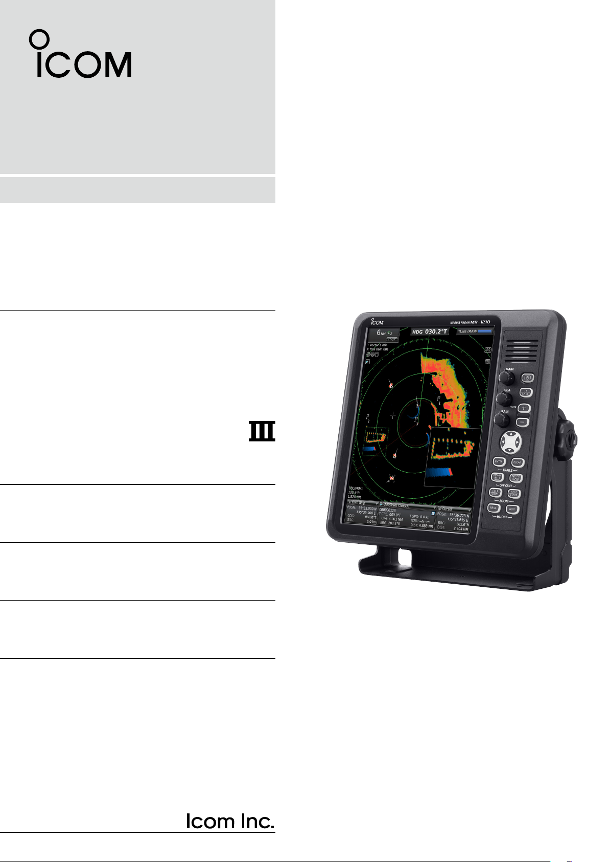
MARINE RADAR
MR-1210R™
(Radome type)
MR-1210T™
(Open array type: 4 kW)
MR-1210T
(Open array type: 6 kW)
Page 2

SYSTEM COMPONENTS
MODEL NAME DISPLAY UNIT SCANNER UNIT
MR-1210RII
MR-1210TII EX-2780 (Open array type: 4 kW)
MR-1210TIII EX-2780 (Open array type: 6 kW)
12.1-inch Color LCD
SUPPLIED ACCESSORIES
• 12.1-inch Color LCD display unit
Quantity
q Front cover ........................................................... 1
w NMEA connector (PLT-167-P-R) ......................... 1
e NMEA connector (PLT-168-P-R) .......................... 1
r Spare fuse (FGB 15 A) ....................................... 1
t Spare fuse (FGB 5 A: for over 24 V power supply)
........................................................................... 1
y DC power cable ................................................... 1
u Mounting bracket ................................................. 1
i Mounting knob bolts ............................................ 2
o Installation bolts (M6×30) .................................... 5
!0 Installation nuts (M6) ............................................ 5
!1 Spring washers (M6) ......................................... 10
!2 Flat washers (M6) ............................................. 10
!3 Instruction manual ............................................... 1
!4 Operating guide ................................................... 1
!5 Display unit template ............................................ 1
!6 EX-2714 template ................................................ 1
!7 EX-2780 template ................................................ 1
EX-2714 (Radome type)
• EX-2714 (Radome type unit)
Quantity
q System cable (15 m) ........................................... 1
w Installation bolts (M10×50) .................................. 4
e Installation bolts (M10×25) .................................. 4
r Installation nuts (M10) ......................................... 4
t Flat washers (M10) ............................................. 4
y Spring washers (M10) ......................................... 4
• EX-2780 (Open array type unit)
Quantity
q System cable (20 m) ............................................ 1
w Installation bolts (M10×40) .................................. 4
e Installation nuts (M10) ......................................... 4
r Flat washers (M10) ............................................. 4
t Spring washers (M10) ......................................... 4
y Allen wrench ....................................................... 1
u Cap bolts (M8×18 mm) ....................................... 4
i Belleville washers (8L) ........................................ 4
o Sealing washers (T) ............................................ 4
!0 Flat washers (M8) ............................................... 4
!1 Flat washers (AW) ............................................... 4
!2 Ferrite EMI filter .................................................. 1
i
Page 3

The MR-1210RII/MR-1210TII/MR-1210TIII are supplemental aids to navigation and are not
intended to be a substitute for accurate and current nautical charts.
Thank you for choosing this Icom product. The MR-
1210RII, MR-1210TII, and MR-1210TIII marine ra-
dars are designed and built with Icom's state of the art
technology and craftsmanship. With proper care, this
product should provide you with years of trouble-free
operation.
SART signals may not be detected and may
not be displayed on the screen depending
on the SEA, RAIN or IR settings.
BE CAREFUL!
IMPORTANT
READ THIS INSTRUCTION MANUAL CAREFULLY before attempting to operate the radar.
SAVE THIS INSTRUCTION MANUAL. This
manual contains important safety and operating instructions for the MR-1210RII/MR-1210TII/MR-1210TIII.
FEATURES
The MR-1210RII, MR-1210TII, and MR-1210TIII ma-
rine radars are designed especially for fishing boats.
It has powerful transmitting power, a 12.1-inch Color
LCD display and many other advanced features.
EXPLICIT DEFINITIONS
WORD DEFINITION
R DANGER!
R WARNING!
CAUTION Equipment damage may occur.
NOTE
Personal death, serious injury or an
explosion may occur.
Personal injury, fire hazard, or electric shock may occur.
If disregarded, inconvenience only.
No risk of personal injury, fire, or
electric shock.
Follow the settings as below to detect the
SART signals on the screen.
q Select the screen range between 6 NM
to 12 NM with [+/–]. (pp. 1, 16)
w Set the [GAIN] as high as possible.
(pp. 2, 16)
e Set the [SEA] to minimum. (pp. 2, 16)
r Set the [RAIN] to minimum. (pp. 2, 16)
t Turn OFF the Interference Rejection
(IR) function. (p. 19)
y Turn OFF the Echo Stretch function.
(p. 19)
Icom is not responsible for the destruction, damage
to, or performance of any Icom or non-Icom equipment, if the malfunction is because of:
• Force majeure, including, but not limited to, fires,
earthquakes, storms, floods, lightning, other
natural disasters, disturbances, riots, war, or
radioactive contamination.
• The use of Icom marine radar with any equipment
that is not manufactured or approved by Icom.
Icom, Icom Inc. and the Icom logo are registered trademarks of Icom Incorporated (Japan) in Japan, the
United States, the United Kingdom, Germany, France,
Spain, Russia, Australia, New Zealand, and/or other
countries.
ii
Page 4

PRECAUTIONS
For Display unit:
R WARNING! NEVER let metal, wire or other
objects contact the inside of the display unit, or make
incorrect contact with connectors on the rear panel.
This could cause an electric shock or damage the
display unit.
R WARNING! NEVER apply AC voltage to the DC
connector of the display unit. This could cause a re
or damage the display unit.
R WARNING! NEVER apply more than 42 V DC
to the DC connector of the display unit. This could
cause a re or damage the display unit.
R WARNING! NEVER touch or operate the display
unit with wet hands. This could cause an electric
shock or damage the display unit.
R WARNING! NEVER open the display unit. There
are no user adjustment points. This could cause an
electric shock and incorrect reassembly may cause a
re hazard.
R WARNING! NEVER operate the radar during a
lightning storm. It may result in an electric shock,
cause a re or damage the display unit. Always
disconnect the power source and scanner unit before
a storm.
R WARNING! NEVER reverse the DC power cable
polarity. This could cause a re or damage the display
unit.
R WARNING! NEVER remove the fuse holder on the
DC power cable. Excessive current caused by a short
could cause a re or damage the display unit.
CAUTION: DO NOT use or place the display unit in
areas with temperature below –15˚C (+5˚F) or above
+55˚C (+131˚F).
CAUTION: DO NOT
Benzine or alcohol when cleaning, the display unit, as
they will damage the display unit surfaces.
CAUTION: DO NOT place the display unit in
excessively dusty environments.
DO NOT place the display unit near heating
equipment or in direct sunlight or where hot or cold
air blows directly onto it.
DO NOT place the display unit in areas that could
block air passage or put anything around the display
unit. This will obstruct heat dissipation.
KEEP the display unit out of the reach of
unauthorized persons.
KEEP the display unit away from heavy rain, and
never immerse it in the water.
The display unit meets IPX4 requirements for splash
resistance when the supplied connection cable,
scanner unit are connected.
use harsh solvents such as
However, if it is dropped, splash resistance cannot be
guaranteed because of possible damage to the case
or the waterproof seals.
The LCD display may have cosmetic imperfections
that is displayed as small dark or light spots. This is not
a malfunction or defect, but a normal characteristic of
LCD display.
For Scanner unit:
R DANGER: HIGH VOLTAGE! NEVER open the
scanner unit. The scanner unit contains high voltage
that could be fatal. And there are no user adjustment
points. All repairs and adjustments MUST be made
by a qualied electronics technician at your Marine
Navigation Dealer.
For qualified electronics technician only:
R
DANGER: HIGH VOLTAGE! High voltages of up to
3,500 volts are used in the scanner unit. Although
prudent measures for safety have been adopted,
sufcient care must be taken in the operation,
maintenance and adjustment of the scanner unit.
Electric shock of 1,000 volts or more may cause
electrocution and death, even an electric shock of
only 100 volts may be fatal.
R DANGER: HIGH VOLTAGE! DO NOT turn OFF the
radar
’s power and do not reach inside the scanner
unit before you have:
• discharged the capacitors by disconnecting the
system cable from the radar unit for 5 minutes.
• checked that no electric charges remain inside
the device.
Also, it is recommended to wear dry insulated
rubber gloves. NEVER use both hands
simultaneously, keep one hand in your pocket.
R
WARNING: RADIATION HAZARD!
Radiation emitted from the scanner unit can be
harmful, particularly to your eyes. To avoid harmful
radiation, turn
working on the scanner unit.
DO NOT use or place the scanner unit in areas with
temperature below –25˚C (–13˚F) or above +70˚C
(+158˚F).
NEVER immerse the scanner unit in the water.
The scanner unit meets IPX6
pressure water jet resistance.
However, if the scanner unit is dropped, highpressure water jet resistance cannot be guaranteed
because of possible damage to the cases or the
waterproof seals.
* Except for the cable connectors. They meet IPX4
requirements while connecting to the radar unit.
OFF the radar’s power
*
requirements for high-
before
iii
Page 5

TABLE OF CONTENTS
SYSTEM COMPONENTS .......................................... i
SUPPLIED ACCESSORIES ....................................... i
IMPORTANT ...............................................................ii
FEATURES .................................................................ii
EXPLICIT DEFINITIONS ............................................ii
PRECAUTIONS .........................................................iii
1. PANEL DESCRIPTION .................................... 1–4
■ Front panel .................................................................1
■ Screen........................................................................3
2. MENU SCREEN ............................................. 5–14
■ Entering Menu screen ................................................ 5
■ Color menu ................................................................5
■ Trail menu ..................................................................6
■ Display menu .............................................................6
■ Target menu ...............................................................7
■ ATA menu ................................................................... 7
■ AIS menu ...................................................................8
■ Video menu .............................................................. 10
■ System menu ........................................................... 10
■ Initial menu ...............................................................12
■ AIS List menu ...........................................................13
■ AIS Own menu ......................................................... 14
■ Status menu ............................................................. 14
■ Port Monitor menu ...................................................14
■ Scanner Monitor menu .............................................14
■ Safety Message menu .............................................14
3. BASIC OPERATION ..................................... 15-24
■ Checking the installation .......................................... 15
■ Turning power ON/OFF ............................................15
■ Basic operation ........................................................16
■ Brilliance/Color adjustment ...................................... 17
■ RAIN function ........................................................... 18
■ SEA function ............................................................ 18
■ IR function ................................................................ 19
■ Echo Stretch function ............................................... 19
■ OFF CENTER function ............................................19
■ Zoom function ......................................................... 20
■ Long pulse function .................................................. 20
■ Trail function .............................................................21
■ Power save function .................................................22
■ Ship speed indication ............................................... 23
■ Waypoint indication ..................................................23
■ Bearing setting ......................................................... 24
4. DISTANCE AND DIRECTION MEASUREMENTS ..
■ Distance measurement ............................................ 25
■ Bearing and Distance measurement .......................27
■ Advanced measurements ........................................27
25–27
5. ALARM FUNCTION ..................................... 29–30
■ Setting Alarm zone ..................................................29
■ Setting Zone alarm type ...........................................30
6. ATA OPERATION ......................................... 31–33
■ ATA (Automatic Tracking Aid) ...................................31
■ The ATA function ON or OFF ................................... 31
■ ATA settings .............................................................31
■ Related settings ....................................................... 32
■ ATA operation ........................................................... 32
■ Plotting marks .......................................................... 33
■ Course and speed vector ......................................... 33
■ Plots (ATA) ...............................................................33
7. AIS OPERATION ......................................... 34–38
■ AIS (Automatic Identification System) ...................... 34
■ The AIS Display ON or OFF ....................................34
■ AIS settings .............................................................. 34
■ Related settings ....................................................... 35
■ Description of the AIS display ..................................36
■ AIS operation ...........................................................37
■ Status of the vessel icon .......................................... 38
■ Plots (AIS) ................................................................ 38
8. BASIC RADAR THEORY ................................... 39
■ Sidelobe echoes ......................................................39
■ Indirect echoes.........................................................39
■ Multiple echoes ........................................................ 40
■ Minimum range ........................................................40
■ Blind and Shadow sectors .......................................41
■ Target resolution ......................................................41
9. INSTALLATION AND CONNECTIONS ....... 42–51
■ Connecting the units ................................................ 42
■ Power source requirement .......................................42
■ Ground connection...................................................42
■ Installing the display unit .......................................... 43
■ Mounting the EX-2714 scanner unit.........................45
■ Wiring the EX-2714 system cable ........................... 46
■ Mounting the EX-2780 scanner unit.........................47
■ Wiring the EX-2780 system cable ........................... 48
■ Attaching the EX-2780 scanner unit ........................49
■ Installing the UX-234 Video output unit ....................50
10. OTHER FUNCTIONS ................................... 52–28
■ TLL function ............................................................. 52
■ Select the language ................................................. 53
■ Simulation screen ....................................................53
■ Antenna rotation speed ............................................ 54
■ Timing adjustment....................................................54
■ Heading adjustment ................................................. 55
■ Range selection ....................................................... 56
■ Saving and loading settings ..................................... 57
■ Resetting .................................................................. 58
11. ERROR MESSAGE ............................................ 59
■ Error message list .................................................... 59
■ AIS error message list..............................................59
12. MAINTENANCE ................................................. 60
■ Periodic maintenance ..............................................60
■ Scanner unit maintenance ....................................... 60
■ Display unit maintenance ......................................... 60
13. SPECIFICATIONS ........................................ 61–62
■ General ....................................................................61
■ Display unit .............................................................61
■ Scanner unit ............................................................. 61
■ Options.....................................................................62
14. EXTERNAL DATA LIST ..................................... 63
iv
Page 6
1
TX
SAVE
ENTER CLEAR
MODE
ALM
+
-
MENU
TLL
EBL2
VRM2
EBL1
VRM1
BRILL
TRAILS
OFF CENT
ZOOM
HL OFF
GAIN
SEA
RAIN
GAIN
SEA
RAIN
TX
SAVE
ENTER
CLEAR
TRAILS
ALM
MODE
OFF CENT
EBL1
VRM1
BRILL
MENU
TLL
HL OFF
EBL2
VRM2
ZOOM
AUTO
ACQ
ACQ TLL
MARINE RADAR
MR-1210
e
r
q
w
t
u
o
!1
y
i
!2
!9
!8
!7
!6
!5
!4
!3
e
r
q
w
t
u
o
!1
y
i
!2
!9
!8
!7
!6
!5
!4
!3
!0 !0
Control panel (English) Control panel (Chinese)
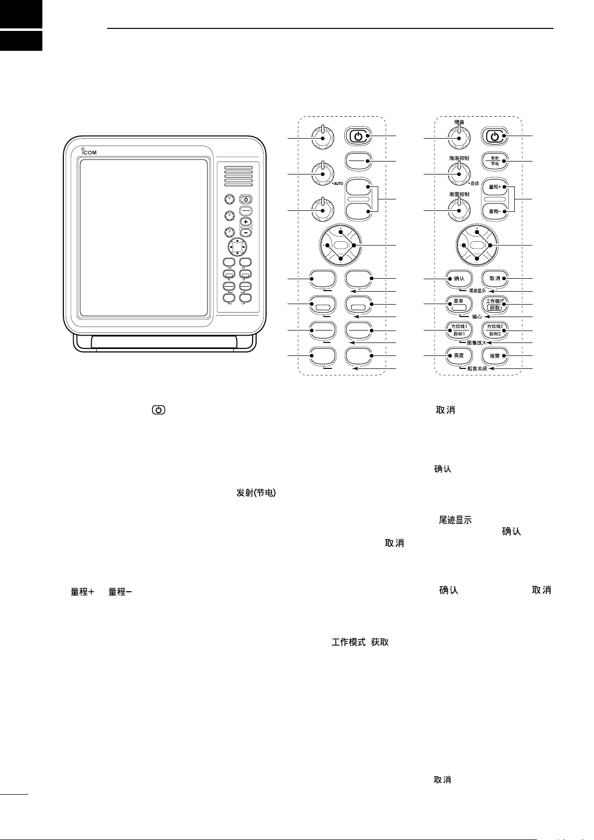
PANEL DESCRIPTION
■ Front panel
q POWER SWITCH [ ] (p. 16)
Push to turn the radar power ON or OFF.
• The initial screen is displayed and a beep sounds after
the power has been turned ON.
• The magnetron inside the scanner unit warms up for 90
seconds and the warm up time is counted down on the
screen.
w TRANSMIT/SAVE KEY [TX (SAVE)]/ [ ]
➥ Push to toggle between the TX mode and the
standby mode. (p. 16)
➥ Hold down for 1 second to turn ON the power
save function. The radar for TX interval scan is
fixed at 10 revolutions. (p. 22)
• Select the save time in the System menu.
e RANGE UP/ DOWN KEYS [+]/[–]/
[ ]/[ ] (p. 16)
Push [+] to increase the screen range.
Push [–] to decrease the screen range.
r UP, DOWN, LEFT, RIGHT KEYS [p] [q] [t] [u]
➥ Sets the EBLs, VRMs, alarm area, ATA target,
AIS target, and so on.
➥ In the Menu screen, push [t] or [u] to select
the Menu group, or push [p] or [q] to select the
menu items.
➥ In the normal operating mode, push a combina-
tion of the [p]/[t], [p]/[u], [q]/[t], or [q]/[u]
to move the cross line cursor to the upper left,
upper right, lower left, or lower right.
1
t CLEAR KEY [CLEAR]/[
]
➥ In the Menu screen, push to cancel the Submenu
or Option selection mode. (p. 5)
➥ Hold down for 1 second to turn the activated AIS
target into a sleeping target. (p. 38)
• Hold down [ENTER]/[ ] for 1 second to change
the sleeping AIS target to an activated target.
➥ Hold down for 1 second to release the ATA target
or delete the TLL mark. (pp. 32, 52)
y TRAILS KEY [TRAILS]/[
] (p. 21)
➥ Simultaneously push [ENTER]/[ ] and
[CLEAR]/[ ] to turn the trail function ON or
OFF. This is useful for watching other vessel’s
tracks, and approximate relative speed.
• The Trail settings can be changed in the Trail menu.
➥ Hold down [ENTER]/[ ] and [CLEAR]/[ ]
u MODE•ACQUIRE TARGET KEY [MODE•ACQ]/
[
➥ Push to select the Head-up (H-UP), Stabilized
for 1 second to erase the plotted echoes when
the trail function is ON.
• ]
Head-up (SH-UP), Course-up (C-UP), North-up
(N-UP) or True motion (TM) screens.
• The North-up, Stabilized Head-Up, and Course-up
screens can be selected only when a bearing data
input is connected. (pp. 42, 63)
• The TM screen requires bearing data or position data.
(pp. 42, 63)
• The TM screen is not selectable in the 32 NM or higher range.
➥ Hold down for 1 second to acquire an ATA target
• Hold down [CLEAR]/[ ] for 1 second to release
on the cursor. (p. 32)
the ATA target.
Page 7

PANEL DESCRIPTION
1
i
OFF CENTER FUNCTION [OFF CENT]/[ ] (p. 19)
Simultaneously push [MENU]/[ ] and [MODE]/
[ ] to turn the OFF CENTER function ON or OFF.
• This function is usable in the 24 NM or less ranges.
o EBL2 (VRM2) KEY [EBL2 (VRM2)]/
[ ] (pp. 26–28)
➥ Push to display the EBL2 (Electronic Bearing
Line 2) and the VRM2 (Variable Range Marker 2.)
• Push [t] or [u] to adjust the EBL selector, or push
[p] or [q] to adjust the VRM selector. Then push
[ENTER]/[
• The EBL2 bearing and the VRM2 distance are displayed in the lower right corner of the screen.
• When the EBL1 and the VRM1 are displayed, the
center of the VRM2 is displayed at the intersection
point of the EBL1 and the VRM1.
➥
While holding down [EBL1(VRM1)]/[ ],
hold down [EBL2(VRM2)]/[ ]
] to set the point.
for 1 second to turn the PI (Parallel Index) lines ON or
OFF. (p.26)
!0 ZOOM FUNCTION [ZOOM]/[
] (p. 20)
Simultaneously push [EBL1(VRM1)]/[ ]
and [EBL2(VRM2)]/[ ] to turn the ZOOM
function ON or OFF. The ZOOM function enlarges the
target to two times normal size.
• Move the cursor to the target, then turn ON the function.
• The zoomed area is displayed by the doted square.
!1 ALARM KEY [ALM]/[ ] (p. 29)
➥ Push [ALM]/[ ] to select the Alarm function,
ALM1, ALM2, ALM1 & ALM2, or OFF.
➥ Hold down [ALM]/[ ] for 1 second to enter the
alarm area setting mode.
• Push [p], [q], [t], or [u] to move the cross cursor to
the zone starting point, then hold down [ALM]/[
for 1 second. The starting ring of the zone is created.
Then push [p], [q], [t], or [u] to fix the finish point,
and then push [ALM]/[
will automatically form.
]. The desired alarm zone
]
!2 HEADING LINE OFF FUNCTION [HL OFF]/
[ ] (p. 16)
While holding down [BRILL]/[ ] and [ALM]/
[ ], the heading line is temporarily turned OFF.
• The rings or other objects can also be turned OFF when the
“HL OFF Mode” item in the System menu is set to “All.” (p. 11)
!3
DISPLAY BRILLIANCE KEY [BRILL]/[ ] (p. 17)
➥
Push to display the Brilliance/Color setting box.
• The key backlight can be adjusted in this setting box.
• The brightness of the symbols, characters and illumina-
tions can be independently adjusted in the Color menu.
➥ Push to increase or decrease the brilliance of the
picture on the display.
➥ Hold down for 1 second to select maximum bril-
liance.
!4 EBL1 (VRM1) KEY [EBL1 (VRM1)]/
[
] (pp. 26–28)
➥ Push to display the EBL1 (Electronic Bearing
Line 1) and the VRM1 (Variable Range Marker 1.)
• Push [t] or [u] to adjust the EBL selector, or push
[p] or [q] to adjust the VRM selector. Then push
[ENTER]/[
• The EBL1 bearing and the VRM1 distance are displayed in the lower left corner of the screen.
• When the EBL1 and the VRM1 are displayed, the
beginning of the EBL2 is displayed at the intersection
point of the EBL1 and the VRM1.
➥
While holding down [EBL1(VRM1)]/[ ],
hold down [EBL2(VRM2)]/[ ]
] to set the point.
for 1 second to turn the PI (Parallel Index) lines ON or
OFF.
(p.26)
!5 MENU KEY [MENU•TLL]/[ •TLL]
➥ Push to enter or exit the Menu screen. (pp. 5–14)
• Push [t] or [u] to select the Menu groups, or push
[p] or [q] to select the items.
➥ Hold down for 1 second to output the position
information where the cursor is placed, to the
NMEA output terminals. (p. 52)
• TLL output requires bearing data and position data.
• The target mark can be displayed, depending on the
setting in the “TLL Mode” item of the System menu.
(p. 11)
!6 ENTER KEY [ENTER]/[ ]
➥ Push to set the ATA, AIS, TLL, or WPT target to
the selected mode. (pp. 23, 32, 37)
➥ In the Menu screen, push to enter the Submenu
or Option selection mode, or push to save the
setting. (p. 5)
➥ Hold down for 1 second to turn the sleeping AIS
target into an activated target. (p. 38)
• Hold down [CLEAR]/[ ] for 1 second to change
the activated AIS target to a sleeping target.
!7
RAIN CLUTTER CONTROL [RAIN]/[ ] (p. 18)
Eliminates echoes from rain, snow, fog, and so on.
Rotate the control fully counter clockwise to deacti-
vate the RAIN function.
• The RAIN icon ( ) disappears.
!8
SEA CLUTTER CONTROL [SEA]/[ ] (p. 18)
Eliminates echoes from waves in close range.
Reduces the receiver gain for close objects within a
radius of approximately 8 nautical miles to eliminate
sea clutter.
Rotate the control fully clockwise to activate the au-
tomatic SEA control function.
•
The SEA icon ( ) is displayed in the upper left of the screen.
• “AUTO” is displayed below the SEA icon ( ) when the
automatic control function is active.
• Under normal conditions set the SEA to minimum.
• Use this control with caution when the sea is rough.
!9 GAIN CONTROL [GAIN]/[ ] (p. 16)
Adjusts the receiver amplifier gain.
• Clockwise rotation increases the gain.
• The increased gain may increase screen noise.
2
Page 8
1
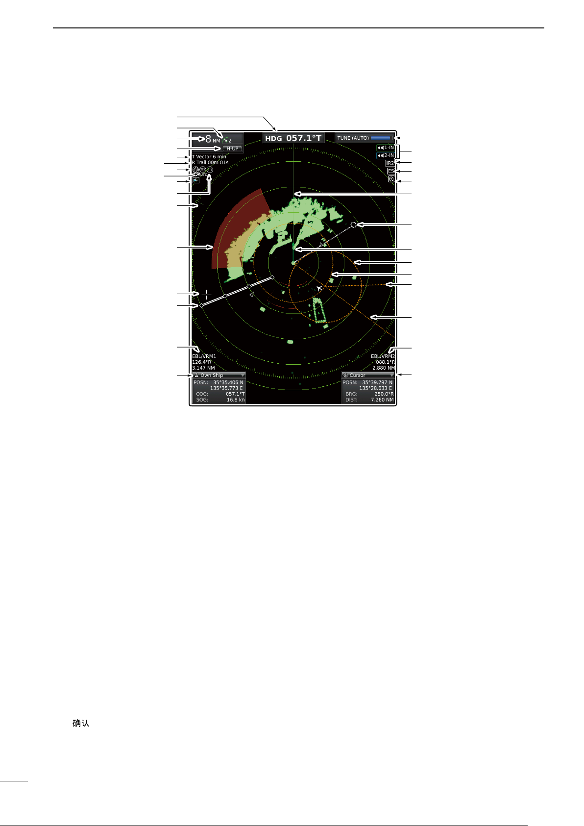
PANEL DESCRIPTION
■ Screen
y
i
q
w
e
r
t
u
o
!0
!1
#0
@9
@8
@7
@6
@5
@4
!2
!3
!4
!5
!6
q HEADING INDICATOR
Shows the heading readout.
• HDG: When the “Bearing Input” item in the Initial menu
is set to “NMEA,” “N+1,” or “AUX.”
• COG: When the “Bearing Input” item in the Initial menu
is set to “GPS” or “GPS-L.”
• The HDG readout indicates the bow of the vessel’s
heading in a clockwise direction from north.
• T: True Bearing, M: Magnetic bearing
w FIXED RING RANGE READOUT (p. 25)
Shows the interval range of the fixed ring.
• This readout is displayed when the “Ring Brill” item in
the Color menu is set to ON (1 to 3).
e SCREEN RANGE READOUT (p. 25)
Shows the range of the displayed screen.
• Nautical miles (NM), kilometers (km), or miles (SM) can
be selected as the distance unit in the Initial menu.
r MODE INDICATOR
Head-up, Stabilized Head-up, Course-up, North-up
and True motion screens are selectable.
• N-UP, SH-UP, and C-UP screens require external bear-
ing data.
• The TM screen requires bearing data and position data.
• Move the cursor on the indicator, then push [ENTER]/
[
] to select the Head-up (H-UP), Stabilized Head-up
(SH-UP), Course-up (C-UP), North-up (N-UP) or True
motion (TM) screens.
@3
This Display example is
@2
set to Wide in the “PPI
@1
Area” item of the Display
@0
menu.
!9
!8
!7
t VECTOR INDICATOR (p. 7)
➥ Shows the ATA, AIS and Own vector type.
• T: True vector, R: Relative vector
➥ Shows the vector time. Select the vector time in
the “Vector Time” item of the Target menu.
y TRAILS INDICATOR (p. 21)
Shows the trail time.
• The echo remains, with gradation, during the trail time
period on the screen. (Except for the trail time; ∞)
• Progressing time counter starts counting until the timer
reaches the trail time.
• R: Relative trail
u RAIN CONTROL ICON (p. 18)
Displayed when the RAIN function is used.
i AUTO SEA ICON (p. 18)
➥ Displayed when the SEA control function is used.
➥ “AUTO” is displayed below this icon when the au-
tomatic SEA control function is used.
o AIS ICON (p. 36)
Displayed when a valid VDM sentence is input from
the [NMEA1] (AIS) port.
The indicator disappears if the AIS signal is not re-
ceived for 6 minutes and 40 seconds.
3
Page 9

PANEL DESCRIPTION
1
!0 LONG PULSE ICON (p. 20)
Displayed when the long pulse is used.
!1 NORTH MARK
The north mark indicates the true north direction.
!2 ALARM ZONE (p. 29)
Displays the alarm zone.
• Displayed when the alarm function is used.
!3 CROSS LINE CURSOR
Used to measure the bearing and distance, setting
the alarm zone, selecting the ATA/AIS targets, and
so on.
• Push [p], [q], [t], or [u] one or more times to move the
cursor.
!4 FIXED RANGE RINGS (p. 25)
Displays the distance at fixed intervals from the own
position. The interval distance is indicated by the
ring range readout (w).
• These rings are displayed when the “Ring Brill” item in
the Color menu is set to ON (1 to 3).
!5 EBL/ VRM1 READOUTS (pp. 26–28)
Displays the bearing of the EBL1 (Electronic Bear-
ing Line) and the distance of the VRM1 (Variable
Range Marker) when the EBL1 and the VRM1 are
used.
• Nautical miles (NM), kilometers (km), or miles (SM) can
be selected in the Initial menu as the distance unit.
!6 OWN SHIP INFORMATION
➥ Displays your own ship’s latitude and longitude
when external NMEA data in 0183 format is connected.
• To display the position, NMEA 0183 data is neces-
sary.
➥ Displays the vessel’s course and speed. (p. 23)
• The speed unit in nautical miles (kn), kilometers
(km/h), or miles (mph) can be selected as the speed
unit in the Initial menu.
!7 CURSOR INFORMATION
➥ Displays cursor latitude and longitude when ex-
ternal NMEA data in 0183 format is connected.
➥ Displays the bearing and distance to the cursor.
• R: Relative bearing, T: True Bearing, M: Magnetic
bearing.
• To display the cursor bearing, bearing data and posi-
tion data are required.
!8 EBL/ VRM2 READOUTS (pp. 26–28)
Displays the bearing of the EBL2 (Electronic Bear-
ing Line) and the distance of the VRM2 (Variable
Range Marker) when the EBL2 and the VRM2 are
used.
• Nautical miles (NM), kilometers (km), or miles (SM) can
be selected as the distance unit in the Initial menu.
• The PI indicator is displayed instead, when the PI (Parallel Index) lines function is ON.
(p. 26)
!9 EBL1 (pp. 26–28)
@0 EBL2 (pp. 26–28)
Used to measure bearing.
When a target is selected, the EBL/VRM1 readouts
(!5) or the EBL/VRM2 readouts (!8) display its bearing.
@1 VRM1 (pp. 26–28)
@2 VRM2 (pp. 26–28)
Used to measure distance.
When a target is selected, the EBL/VRM1 readouts
(!5) or the EBL/VRM2 readouts (!8) display its distance.
@3 OWN SHIP VECTOR INDICATOR (p. 6)
Displays the vector of your own ship.
@4 WAYPOINT MARKER (p. 23)
Displays a waypoint that is received from navigation
equipment.
• This marker is displayed when the “WPT Display” item in
the Display menu is set to ON.
• To display the Waypoint marker, bearing data and NMEA
data in 0183 format are necessary. (p. 63)
@5 HEADING LINE (p.16)
The heading line indicates the vessel bow direction.
@6 ZOOM ICON (p. 20)
Displayed when the zoom function is used.
• Simultaneously push [EBL1(VRM1)]/[ ]
and [EBL2(VRM2)]/[
function ON or OFF
] to toggle the ZOOM
@7 ECHO STRETCH ICON (p. 19)
Displayed when the echo stretch function is used.
• This icon is displayed when the “Echo Stretch” item in
the Video menu is set to ON.
@8 IR ICON (p. 19)
Displayed when the IR (Interference Rejection)
function is used.
• This icon is displayed when the “IR” item in the Video
menu is set to ON (1 or 2).
@9 ALARM ICONS (p. 29)
Displayed when the alarm function is used.
#0 TUNING MODE INDICATOR (p. 16)
➥ Displays the tuning mode selection.
• “TUNE (AUTO)” is displayed when the “TUNE” item
in the Video menu is set to “Auto” or “TUNE (MAN)” is
displayed when the “TUNE” item is set “Manual.”
➥ Shows the receiver tuning level.
Information boxes (!6 and !7):
Move the cursor on the title bar, then push [ENTER]/
[ ] to collapse or expand the information box.
4
Page 10
ENTER
CLEAR
MENU
TLL
ENTER CLEAR
MENU
TLL
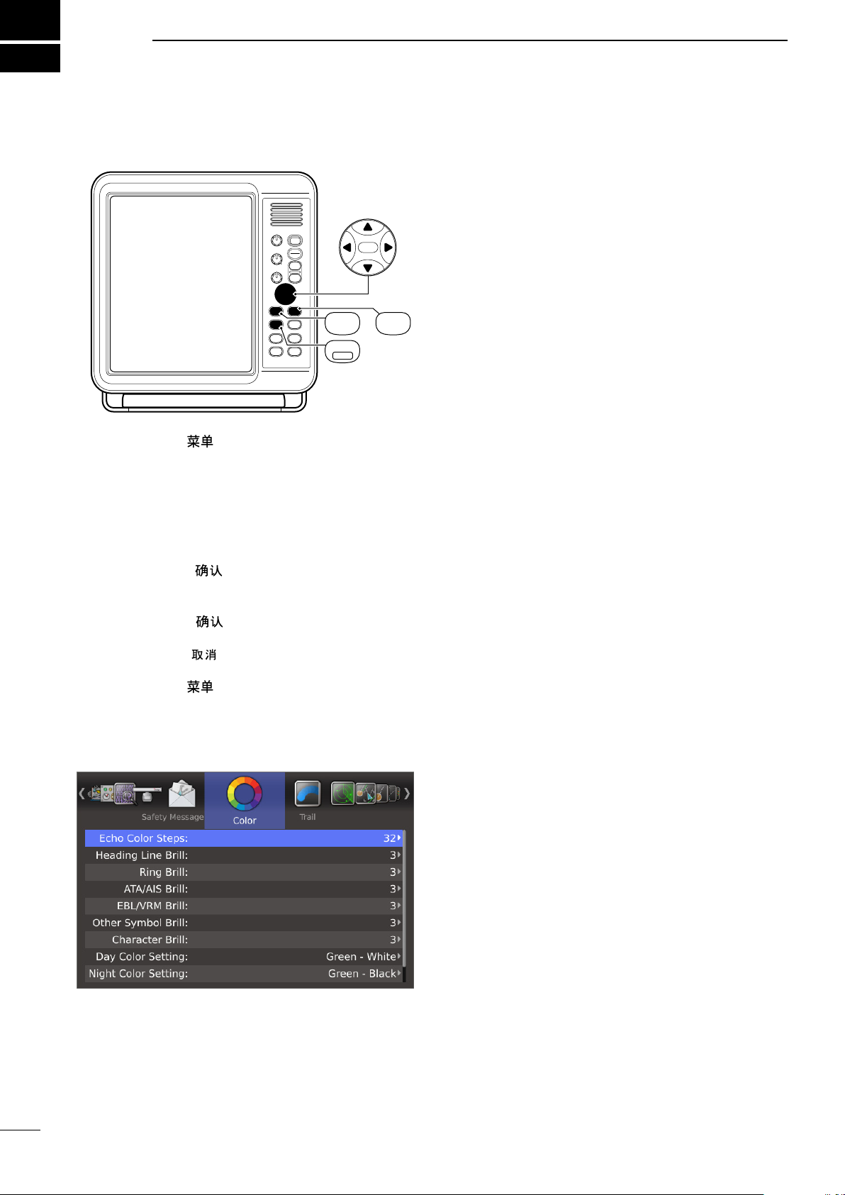
2
MENU SCREEN
■ Entering Menu screen
q Push [MENU]/[ ] to enter the Menu screen.
w Push [t] or [u] to select the menu.
• You can select the “Color,” “Trail,” “Display,” “Target,” “ATA,”
“AIS,” “Video,” “System,” “Initial,” “AIS List,” “AIS Own,”
“Status,” “Port Monitor,” “Scanner Monitor,” or “Safety
Message” menus.
e Push [p] or [q] to select the item.
• The selected item is highlighted.
r Push [ENTER]/[ ] to enter the option selection
mode.
t Push [p] or [q] to select an option.
y Push [ENTER]/[ ] to save the setting and exit
the option selection mode.
• Push [CLEAR]/[ ] to cancel the setting and exit the
mode, if desired.
u Push [MENU]/[ ] to exit the Menu screen.
D Heading Line Brill
Sets the Heading line brilliance to 1 (dark), 2 (normal),
or 3 (bright).
D Ring Brill*
• OFF: The fixed range rings are not displayed, and
the scale is displayed in dark, the same as 1
(dark).
• 1 to 3: The circles and scale are displayed in 1
(dark), 2 (normal) or 3 (bright).
D ATA/AIS Brill*
Sets the Brilliance of the ATA or AIS symbols to 1
(dark), 2 (normal), or 3 (bright).
ATA: Automatic Tracking Aid
AIS: Automatic Identification System
D EBL/VRM Brill*
Sets the Brilliance of the EBL or VRM to 1 (dark), 2
(normal), or 3 (bright).
EBL: Electronic Bearing Lines
VRM: Variable Range Markers
D Other Symbol Brill*
Sets the Brilliance of other than above symbols to 1
(dark), 2 (normal), or 3 (bright).
This setting is not applied to an echo.
D Character Brill*
Sets the Brilliance of the character out of the scale to
1 (dark), 2 (normal), or 3 (bright).
■ Color menu
* When the background color is set to White, 1 is bright
and 3 is dark.
D Day Color Setting
Sets the display color for day time to Green-White,
Yellow-White, Red-White, or Multi-White.
XX-White: The background color is fixed to white.
D Night Color Setting
Sets the display color for night time to Green-Black,
Yellow-Black, Red-Black, or Multi-Black.
XX-Black: The background color is fixed to black.
D User Color Setting
Sets the display color for custom settings to Green,
Yellow, Red, or Multi.
D Echo Color Steps
• 8: The gradation of an echo is displayed in 8
steps.
The 8 steps are 0, 1~3, 4~7, 8~11, 12~16,
17~21, 22~26, and 27~31.
• 32: The gradation of an echo is displayed in 32
steps.
5
You can also select the background color from Black,
Dark Blue, or White.
Page 11
MENU SCREEN
2
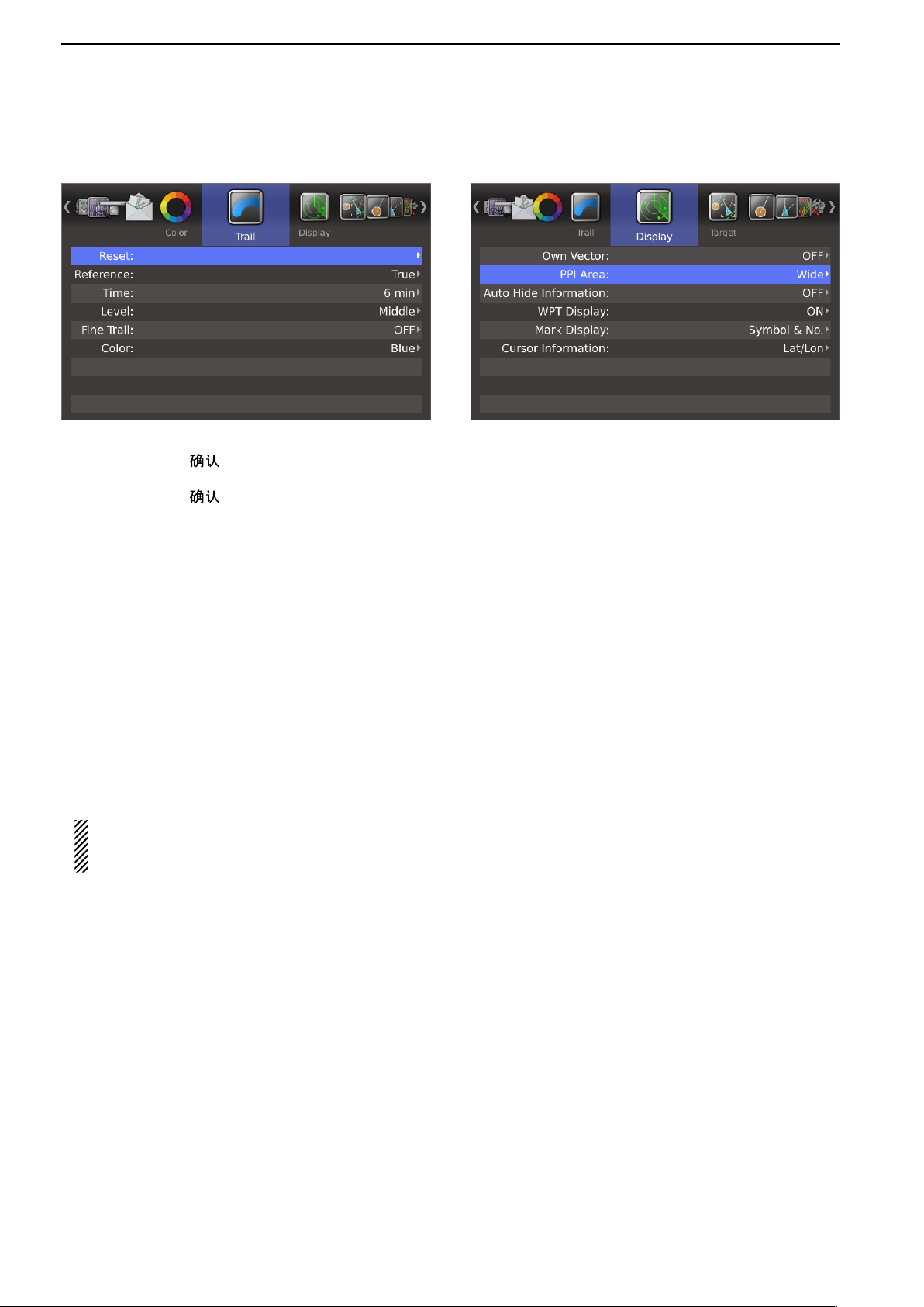
■ Trail menu
D Reset
q Push [ENTER]/[ ].
• The dialog box “Sure?” is displayed.
w Push [ENTER]/[ ] again to clear the trail.
D Reference
Selects the reference of trail.
• True: Regardless of the movement of your vessel, the trail of other vessels displays a
real movement over ground. Therefore,
a stopped targetʼs trail is not displayed.
The true trail requires a heading signal and
your own vesselʼs position information.
• Relative: The trail of other vessels is relative to your
vessel. In this mode, other vesselsʼ movement and your vesselʼs movement are combined, so Relative trail is valid if you want to
look at the relative movement to avoid collisions. However, a stopped targetʼs trail is
also displayed. In that case, it is difficult to
see in some places such as near Islands.
Regardless of this setting, the display acts as the
True trail setting when the True motion (TM)
screen is selected.
D Time
Selects the trail time from 30 seconds, 1 minute, 3 minutes, 6 minutes, 15 minutes, 30 minutes, or ∞.
D Level
Selects the level of the trail.
• Low: Leaves a trail between Low and High levels.
• Middle: Leaves a trail between Mid and High levels.
• High: Leaves a trail only at the High level.
D Fine Trail
Selects the thinness of the trail. The Fine trail function
makes the trail thin.
• OFF: Normal trail.
• 1: Fine trail.
• 2: Extra fine trail.
■ Display menu
D Own Vector
• OFF: Does not display your own ship’s vector.
• ON: Displays your own ship’s vector.
• Bearing data and ship speed data are required.
D PPI Area
Selects the PPI (Plan Position Indicator) area.
• Normal: The PPI area is inside the scale.
• Wide: The PPI area is the whole screen.
D Auto Hide Information
Sets whether or not to hide the outside of the scale,
after 10 seconds without any operation.
This setting is effective only when the “PPI Area” item
is set to “Wide.”
• OFF: Always displays the outside of the scale.
• ON: Hides the outside of the scale after 10 seconds has passed with no operation, and displays it again with any operation.
D WPT Display
Sets whether or not to display waypoints.
D Mark Display
Sets whether or not to display marks.
• OFF: The marks are not displayed.
• Symbol: The marks are displayed with icons.
• Symbol & No.: The marks are displayed with icons
and numbers.
D Cursor Information
Selects the information in the Cursor box. The cursor
box displays the information at the point of the cursor.
• Lat/Lon: Displays position information (latitude
and longitude).
• TTG: Displays TTG (Time To Go) information
(TTG, Bearing and Distance).
D Color
Sets the trail color to between Blue, Yellow, Green,
Red, Orange, and White.
6
Page 12
2
MENU SCREEN
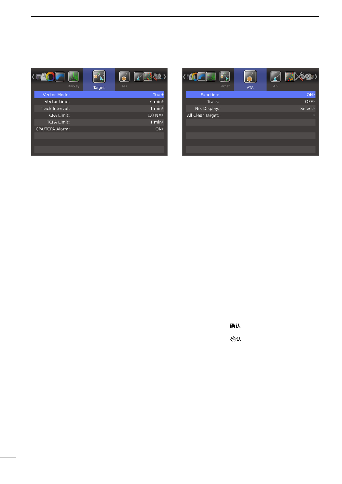
■ Target menu
D Vector Mode
• True: Selects the true vector mode.
• Relative: Selects the relative vector mode.
D Vector time
Sets the vector length (time) to 30 seconds, 1 minute,
3 minutes, 6 minutes, 15 minutes, or 30 minutes.
D Track Interval
The track data is updated at this specified tracking interval. Select the track interval from 15 seconds, 30
seconds, or between 1 and 15 minutes.
■ ATA menu
D Function
• OFF: Turns OFF the ATA (Automatic Tracking Aid)
function.
• ON: Turns ON the ATA function.
D Track
The plot displays the target’s past positions as 5 dots,
during each specified tracking interval.
You can specify the track interval in the “Track Interval”
item of the Target menu.
• OFF: Turns OFF the Track display function.
• ON: Turns ON the Track display function.
After 5 dots are displayed, the oldest dot disappears at
the time when the next dot is displayed.
D CPA* Limit
Sets the CPA (Closest Point of Approach) limit to between 0.1 and 12.0 NM in 0.1 NM steps.
D TCPA* Limit
Sets the TCPA (Time to CPA) limit time to 30 seconds,
between 1 and 6 minutes, or 12 minutes.
* CPA/TCPA: Closest Point of Approach and Time to
Closest Point of Approach limits are set to give a
warning when a target or targets enter those limits
around your own vessel.
D CPA/TCPA Alarm
Sets whether or not to sound the CPA/TCPA alarm.
A CPA/TCPA alarm sounds when both the CPA and
TCPA reach the limit.
D No. Display
Selects the target identification number type that is
displayed at the right side of the mark.
• OFF: Does not display any mark number.
• Select: Displays only the selected mark number.
• All: Displays all mark numbers.
D All Clear Target
Releases all of the ATA targets at the same time.
q Push [ENTER]/[ ].
• The dialog box “Sure?” is displayed.
w Push [ENTER]/[ ] again to release all ATA tar-
gets.
7
Page 13
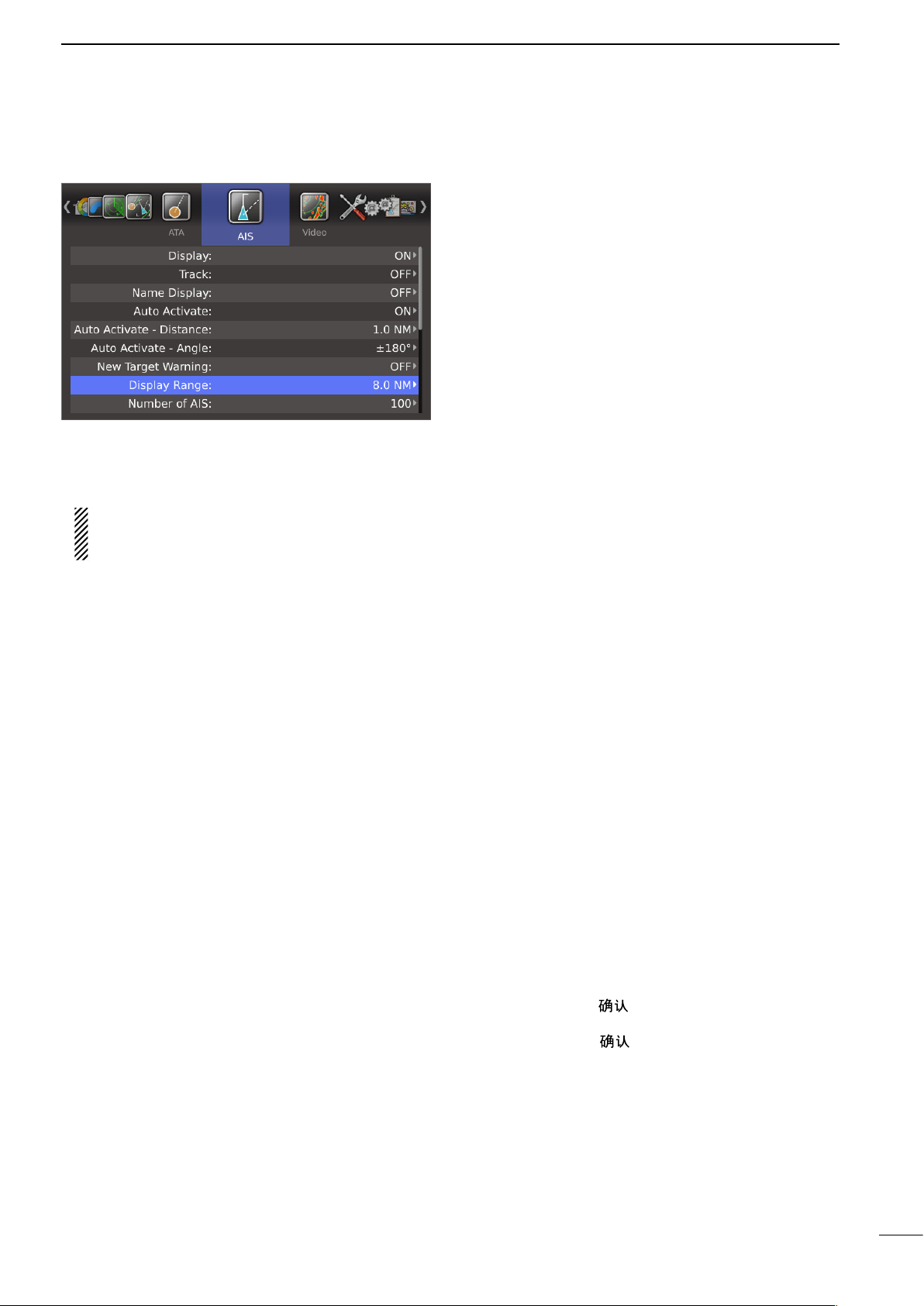
■ AIS menu
D Display
• OFF: Turns OFF the AIS display.
• ON: Turns ON the AIS display.
If an AIS target reaches the CPA and TCPA limits
when “OFF” is selected, this setting is automatically turned ON.
MENU SCREEN
2
D New Target Warning
Sets whether or not to alert when the Auto Activate
function automatically turns the sleeping AIS target
into an activated target.
• OFF: Does not give a warning when the Auto Activate function activates the target.
• ON: Gives a warning when the Auto Activate function activates the target.
D Display Range
Sets the AIS targets display range to between 0.1 and
36.0 NM, or ∞.
• 0.1 to 36.0 NM: Selects the range from your vessel in
0.1 NM steps.
• ∞: Displays all range from your vessel.
D Number of AIS
Selects the maximum number of AIS targets that can
be displayed on the screen to between 10 and 100 in
1 target steps.
D Track
The plot displays the AIS target’s past positions as 5
dots, during each specified tracking interval.
You can specify the track interval in the “Track Interval”
item of the Target menu.
• OFF: Turn OFF the Track display function.
• ON: Turn ON the Track display function.
D Name Display
Selects the AIS target display type.
• OFF: Does not display any name or MMSI
number of the target.
• Select: Displays the vessel name or MMSI number of the selected target.
• Active: Displays the vessel name or MMSI number of all active targets.
D Auto Activate
The Auto Activate function automatically turns the
sleeping AIS target into an activated target when the
AIS target is at the specified distance and angle.
You can specify the distance and angle in the next two
items.
• OFF: Turns OFF the Auto Activate function.
• ON: Turns ON the Auto Activate function.
D Slow Warn
The AIS unit calculated COG (Course Over Ground)
data of a vessel that is at anchor or drifting is unreliable, and therefore the CPA (Closest Point of Approach) and TCPA (Time to CPA) data may not be
correctly calculated. If a vessel is anchored in your
alarm zone, the unreliable data can cause the collision
alarm to sound many times, even if there is no real
danger. To prevent this, when the anchored vessel’s
SOG (Speed Over Ground) is less than this set value,
the Slow Warn function assumes that vessel’s COG
is fixed towards your vessel and an alarm will sound.
• OFF: Turns OFF the Slow Warn function.
• ON: Turns ON the Slow Warn function.
D Slow Warn Speed
• 0.1 to 5.0 kn: Selects the vessel’s speed in 0.1 kn
steps.
D Erase Lost Target
Erases all of the Lost targets at the same time.
When there is no lost targets, this setting is grayed out.
q Push [ENTER]/[ ].
• The dialog box “Sure?” is displayed.
w Push [ENTER]/[ ] again to clear all of the Lost
targets on the screen.
D Auto Activate - Distance
Sets the distance to automatically turn the sleeping
AIS target into an activated target.
• 0.1 to 10.0 NM:
Select the distance from your vessel.
D Auto Activate - Angle
Sets the angle to automatically turn the sleeping AIS
target into an activated target.
• 5 to 180°: Selects the angle with your vessel.
About “Lost Target”: A vessel is regarded as a “Lost
target” after a specified period of time has passed
since the vessel last transmitted data, as described on
the next page.
The “Lost target” icon disappears from the screen 6
minutes and 40 seconds after the vessel was regarded
as a “Lost target.”
8
Page 14

2
MENU SCREEN
■ AIS menu (Continued)
The criteria to become a Lost target
• Class A/B
Nominal re-
Vessel type
Class A
1
Class B
Vessel is at anchor or moored and moving
2
faster than 3 knot
Class A
3
Class B
Class A
4
Class B
5 Vessel is moving between 14 and 23 knots
Vessel is moving between 14 and 23 knots
6
while changing course
7 Vessel is moving faster than 23 knots
Vessel is moving faster than 23 knots while
8
changing course
1
*
AIS Class B does not provide information about the navigation status, anchored or moored.
2
*
CS: Carrier-sense, *3 SO: Self organized
Vessel is at anchor or moored and
not moving faster than 3 knots
Vessel is
knots
Vessel is moving between 0 and
14 knots
Vessel is moving between 2 and
14 knots
Vessel is moving between 0 and
14 knots while changing course
Vessel is moving between 2 and
14 knots while changing course
not moving faster than 2
porting interval
Class A
3 min. 18 min. — — — —
— — 3 min. 3 min. 18 min. 18 min.
10 sec. 60 sec. N/A N/A
10 sec. 60 sec. — — — —
— —
1
3
sec. 60 sec. — — — —
⁄
3
— —
6 sec. 36 sec.
2 sec. 36 sec.
2 sec. 30 sec.
2 sec. 30 sec.
Lost target
maximum
interval Class A
Nominal reporting
interval Class B *
CS *
30 sec. 30 sec. 180 sec. 180 sec.
30 sec. 30 sec. 180 sec. 180 sec.
30 sec. 15 sec. 180 sec. 90 sec.
30 sec. 15 sec. 180 sec. 90 sec.
30 sec. 5 sec. 180 sec. 30 sec.
30 sec. 5 sec. 180 sec. 30 sec.
Lost target maximum
1
interval Class B *
2
SO *
3
CS *
2
SO *
1
3
• Others
Category
SAR 10 sec. 60 sec.
Base station 10 sec. 60 sec.
AtoN 3 min. 18 min.
Nominal reporting
interval
Lost target
maximum interval
D Safety Message
Sets whether or not to display the message when the
safety message is received.
• OFF: Turns OFF the Safety Message function.
• ON: Turns ON the Safety Message function.
D Favorite AIS
Sets whether or not to alert that the specified MMSI
target gets into the specified range from your vessel.
• OFF: Turns OFF the Favorite AIS function.
• ON: Turns ON the Favorite AIS function.
D Favorite AIS Range
Sets the Favorite AIS display range to between 0.1
and 36.0 NM, or ∞.
• 0.1 to 36.0 NM: Selects the range from your vessel in
0.1 NM steps.
• ∞: Displays all range from your vessel.
D Favorite AIS Target1
D Favorite AIS Target2
D Favorite AIS Target3
Enters the MMSI number of favorite targets.
9
Page 15
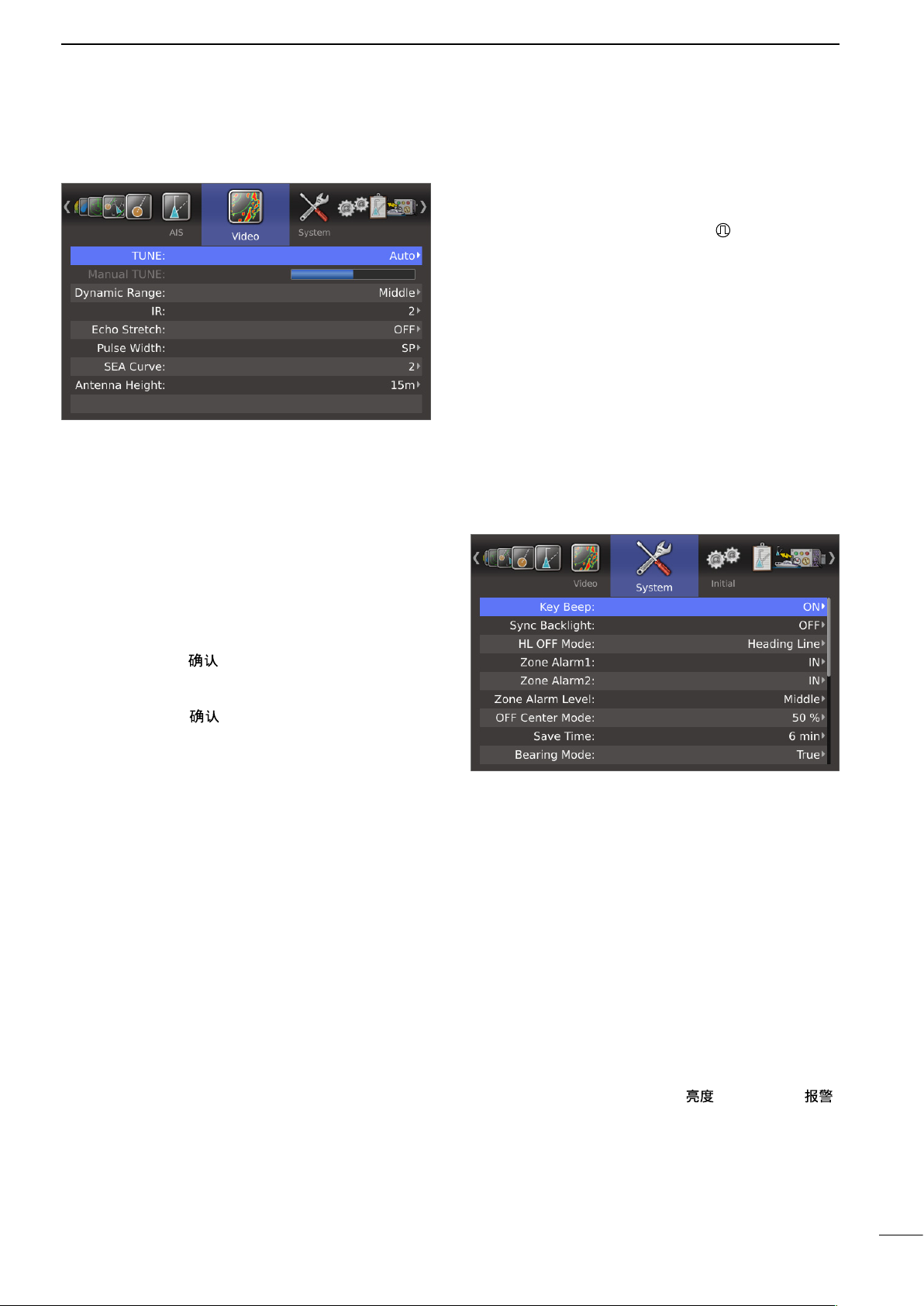
■ Video menu
D TUNE
• Auto: Automatic tuning.
• “TUNE (AUTO)” is displayed in the upper right
corner of the screen.
• Manual: Manual tuning.
• “TUNE (MAN)” is displayed in the upper right
corner of the screen.
MENU SCREEN
2
D Pulse Width
• SP: Sets the pulse width to narrow.
• LP: Sets the pulse width to wide. “ ” is displayed in
the upper left corner of the screen.
D SEA Curve
• The SEA knob can be used to fine tune the sea clut-
ter of the display after one of four main levels are selected, depending on the sea conditions.
D Antenna Height
• Sets the antenna height from the surface of the sea.
5 m, 10 m, 15 m, 20 m, 30 m, 40 m, or 50 m is selectable.
■ System menu
D Manual TUNE
When “Auto” is selected in the “TUNE” item, this setting is disabled.
q
Push [ENTER]/[ ] to enter the adjustment mode.
w Push [t] or [u] to adjust the desired tuning level
(256 levels).
e Push [ENTER]/[ ] again to save and exit the ad-
justment mode.
D Dynamic Range
Selects the dynamic range of the PPI (Plan Position
Indicator).
• Narrow: Narrow dynamic range. Even weak reflections are displayed as strong reflections.
• Middle: Mid dynamic range.
• Wide: Wide dynamic range. You can easily distinguish between weak reflections and strong
reflections.
D IR
• OFF: Turns OFF the Interference Rejection
function.
• 1 or 2 (ON): Turns ON the Interference Rejection
function 1 (Low) or 2 (High).
• “IR1” or “IR2” is displayed in the upper
right corner of the screen.
D Echo Stretch
• OFF: Turns OFF the echo stretch function.
• ON: Turns ON the echo stretch function.
• “ES” is displayed in the upper right corner of the
screen.
D Key Beep
• OFF: Turns OFF* the beep tone.
• ON: Turns ON the beep tone.
* Except for the alarm function.
D Sync Backlight
Sets whether or not to synchronize the brilliance of the
display and key backlight.
• OFF: Individually sets the brilliance of the display
and key backlight. (16 levels each)
• ON: Synchronizes the brilliance of the key backlight to the display. (16 levels)
D HL OFF Mode
Selects the objects to hide temporarily in the Heading
Line OFF mode (while [BRILL]/[ ] and [ALM]/[ ]
are simultaneously hold down).
• Heading Line: Turns OFF only the Heading line.
• All: Turns OFF the Heading line, Rings,
and other objects.
10
Page 16

2
MENU SCREEN
■ System menu (Continued)
D Zone Alarm1
D Zone Alarm2
Sets the Zone Alarm1 and Zone Alarm2 settings.
• IN: An alarm sounds when the target comes into
the zone.
• OUT: An alarm sounds when the target goes out of
the zone.
D Zone Alarm Level
Selects the target detection parameter of zone alarm
1 and 2.
Selectable parameters are Low, Middle and High.
D OFF Center Mode
Sets the OFF Center setting when the OFF Center
function is ON.
• 25, 50, 75%: The center of the display area moves
to the front of the bow, and the bow
view increases.
• Cursor: The center of the display area shifts
to the cursor, and the opposite view
increases.
D Save Time
Selects the standby time during the save mode from 1
min, 6 min, 15 min or 30 min.
• The radar for a TX interval scan is fixed at 10 revolutions.
D Bearing Mode
Select the displayed bearing type, regardless of the
bearing data format (NMEA, N+1, AUX, GPS, or GPS-L).
• True: Select the true North bearing.
• Magnetic: Select the magnetic North bearing.
D Variation
Selects the difference setting between true North and
magnetic North.
• Auto:
Until an effective variation is received, use
• Manual: Manually revises the magnetic variation.
Use the manual setting for the difference
Automatically revises the magnetic variations.
0° for difference between true North and
magnetic North. After an effective variation
is received, use the last data for the difference. The MR-1210 memorize the data until you turn OFF the power.
between true North and magnetic North.
Set the Manual Variation in the next item.
D Bearing Reference
Sets the direction for the EBL (Electronic Bearing Line)
or cursor.
• True: True or magnetic direction
• 360°R: Relative direction
• PT/SB: Bow direction
D Speed Input
Selects the speed input of the vessel from “SOG” or
“Manual.” If you select “Manual,” enter data manually
into the items below, “Manual Speed”, “Manual SET”,
and “Manual Drift.”
D Manual Speed
Sets your vesselʼs speed to between 0.1 and 40.0 kn.
(0.2 ~ 74.0km/h, 0.1 ~ 46.0 mph)
D Manual SET
Sets the Tidal current direction to between 0 and
359.9°T (or M).
D Manual Drift
Sets the Tidal current speed to between 0 and 20.0 kn.
(0 ~ 37.0 km/h, 0 ~ 23.0 mph)
D TLL Mode
• Output: Hold down [MENU]/[ ] for 1 second to
output the position information where the
cursor is positioned, to the NMEA output
terminals.
• Symbol: Hold down [MENU]/[ ] for 1 second to
mark on the screen where the cursor is positioned.
• Output & Symbol:
Hold down [MENU]/[ ] for 1 second to
output the position information and mark on
the screen where the cursor is positioned.
D Transparency Menu
Sets the transparency level of the Menu screen and
Brilliance/Color dialog box to between 0% (Nontransparent) and 70% (Transparent).
D Transparency Info.
Sets the transparency level of the Information box,
Own Ship information box, Cursor information box or
Range/COG/Tune tag to between 0% (Nontransparent) and 70% (Transparent).
11
D Manual Variation
Manually sets the difference between true North and
magnetic North. Selectable angles are 180.0°W (West)
to 180°E (East).
This setting is used when “Variation” is set to “Manual.”
D STBY Mode
Sets the display information in the Standby mode to
Normal or AIS.
D Rev.
Displays the revision number of the firmware.
Page 17
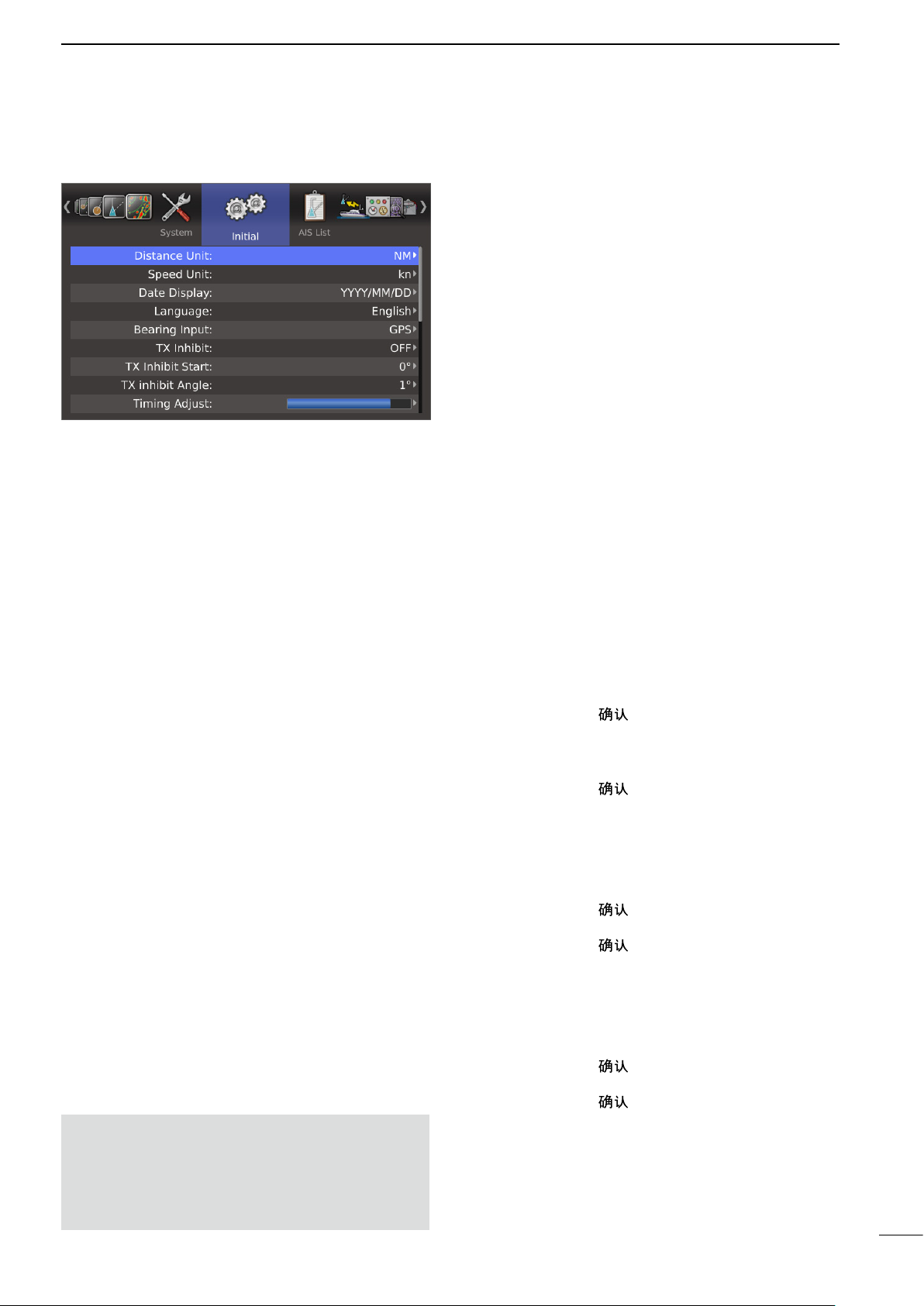
■ Initial menu
D Distance Unit
Selects the distance unit from NM (nautical miles), km
(kilometers), or SM (miles).
D Speed Unit
Selects the speed unit from kn (nautical miles), km/h
(kilometers), or mph (miles).
D Date Display
Selects the Date format from “YYYY/MM/DD,” “MM/
DD/YYYY,” or “DD/MM/YYYY.”
(YYYY: Year, MM: Month, DD: Day)
D Language
Selects the displayed language. (p. 53)
D Bearing Input
Sets the input source of the vessel’s bow information.
• NMEA: NMEA0183 bearing data format.
• N+1: N+1 data format.
• AUX: Other format.
• GPS: Reads NMEA0183 COG format data as
HDG format. (The course may not match
with other HDG format and include errors.)
• When a vesselʼs speed is less than 2 knots, the
direction information is not displayed until the
sped increases to more than 3 knots.
• GPS-L: Reads NMEA0183 COG format data as
HDG format. (The course may not match
with other HDG format and include errors.)
• When a vesselʼs speed is less than 2 knots, the
direction information is fixed.
The display changes only when the vesselʼs
speed increases to more than 3 knots.
• This is in addition to the GPS option to display
the cursor latitude and longitude when the vesselʼs speed is less than 3 knots.
MENU SCREEN
2
D TX Inhibit
Selects whether or not to use the TX inhibit.
D TX Inhibit Start
• 0 to 359°: Enters the start point of the TX inhibit
area.
D TX Inhibit Angle
• 1 to 90°: Enters the TX inhibit area.
D Timing Adjust
Adjusts the sweep timing. (p. 54)
D Heading Adjust
Adjusts the bow compensation between –180° and
+180°. (p. 55)
D Antenna Rotation Speed
Sets the antenna rotation speed to Normal or Slow.
(p. 54)
D Range Ring
Selects the type of range rings from Ring1 (normal) or
Ring 2 (fine). (p. 25)
D Range
Sets the effective ranges. (p. 56)
q Push [ENTER]/[ ] to enter the selection mode.
w Push [p] or [q] to select a desired range.
e Push [t] to set the range OFF or push [u] to set
the range ON.
r Push [ENTER]/[ ] to save the settings.
D Save Settings1
D Save Settings2
D Save Settings3
The settings can be saved. (p. 57)
q Push [ENTER]/[ ].
• The dialog box “Sure?” is displayed.
w Push [ENTER]/[ ] again to save the settings.
D Load Settings1
D Load Settings2
D Load Settings3
The setting can be loaded. (p. 57)
q Push [ENTER]/[ ].
• The dialog box “Sure?” is displayed.
w Push [ENTER]/[ ] again to load the settings.
NOTE: If this item is set to “GPS” or “GPS-L,” COG
(Course Over the Ground) data is used as the bearing.
However, If the vessel’s speed is less than 3
knots, direction accuracy falls. Moreover, the position accuracy or the current actual course may
vary, and therefore display an incorrect direction.
12
Page 18
2
MENU SCREEN
■ Initial menu (Continued)
D Setting Reset
Resets the settings in the Menu screen other than the
settings in the Initial menu. You can reset only in the
Standby mode. (p. 58)
q Push [ENTER]/[ ].
• The dialog box “Sure?” is displayed.
w Push [ENTER]/[ ] again to reset the settings.
D Factory Reset
Resets the settings to the factory default. You can reset
only in the Standby mode. (p. 58)
q Push [ENTER]/[ ].
• The dialog box “Sure?” is displayed.
w Push [ENTER]/[ ] again to load the factory de-
fault.
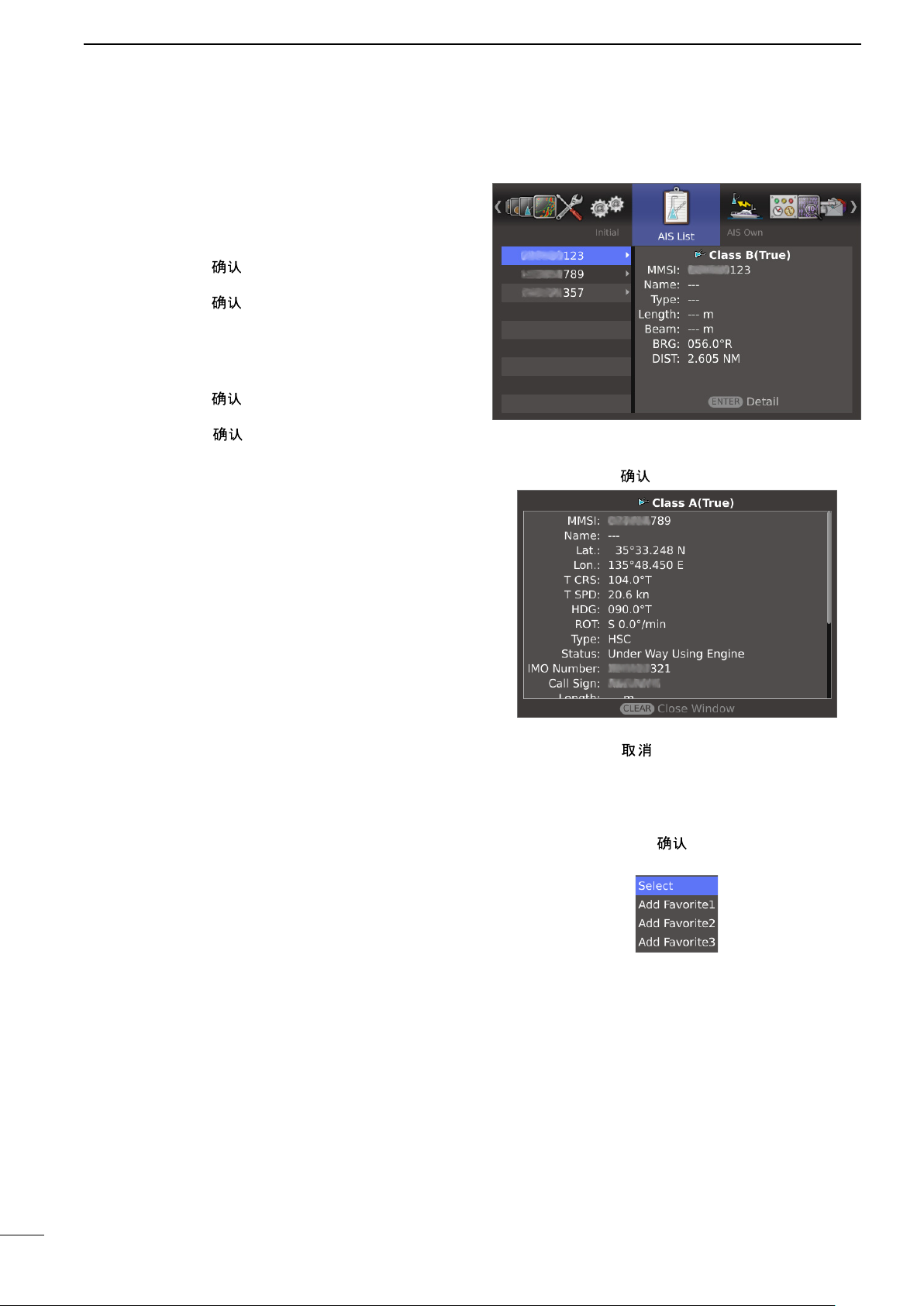
■ AIS List menu
Displays AIS information.
q Push [p] or [q] to select a desired AIS target.
w Push [ENTER]/[ ] to open the detail window.
e Push [p] or [q] to scroll the window.
r Push [CLEAR]/[ ] to close the window.
• When the AIS target is selected, set it to the “Selected AIS target” or register it to “Favorite AIS Target1,
2, or 3.”
q Hold down [ENTER]/[ ] for 1 second to open the
Sub menu.
w Push [p] or [q] to select the option.
Select: Set to the Selected AIS Target.
Add Favorite1, 2, or 3: Register to the Favorite AIS.
13
Page 19
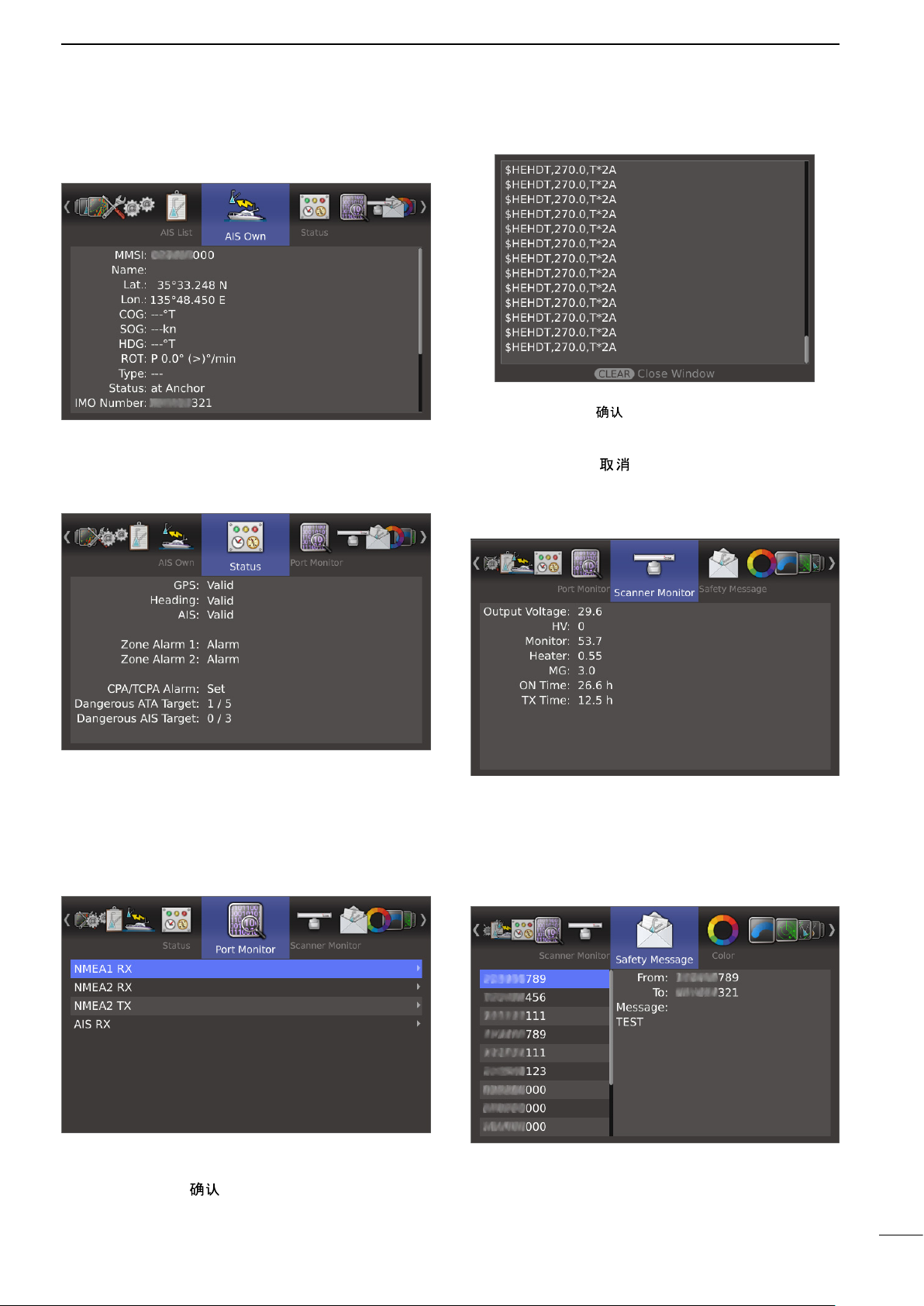
■ AIS Own menu
Displays own AIS information.
■ Status menu
MENU SCREEN
• The display is automatically updated by new status.
• Push [ENTER]/[
again to restart.
• Push [p] or [q] to scroll the window.
e Push [CLEAR]/[ ] to close the window.
] to pause the display update. Push
■ Scanner Monitor menu
2
Displays the status of the GPS, Heading and AIS inputs, alarm settings, and CPA/TCPA alarm settings.
• The CPA/TCPA Alarm Set item indicates the number of
dangerous targets in the total targets.
■ Port Monitor menu
Displays status of the input/output ports.
q Push [p] or [q] to select a desired port.
w Push [ENTER]/[ ] to open the detail window.
Displays the scanner status.
• When the status is fail, the title and value change to
red color.
■ Safety Message menu
Displays the AIS messages.
➥ Push [p] or [q] to select a desired AIS message.
• The message is displayed to the right window.
14
Page 20
3
BASIC OPERATION
■ Checking the installation
Before turning ON the power, be sure all the connections are complete. The checklist to the right may be
helpful for necessary confirmation.
CAUTION: Connect the scanner unit before turning
ON the power. Otherwise the magnetron inside the
scanner unit might be damaged.
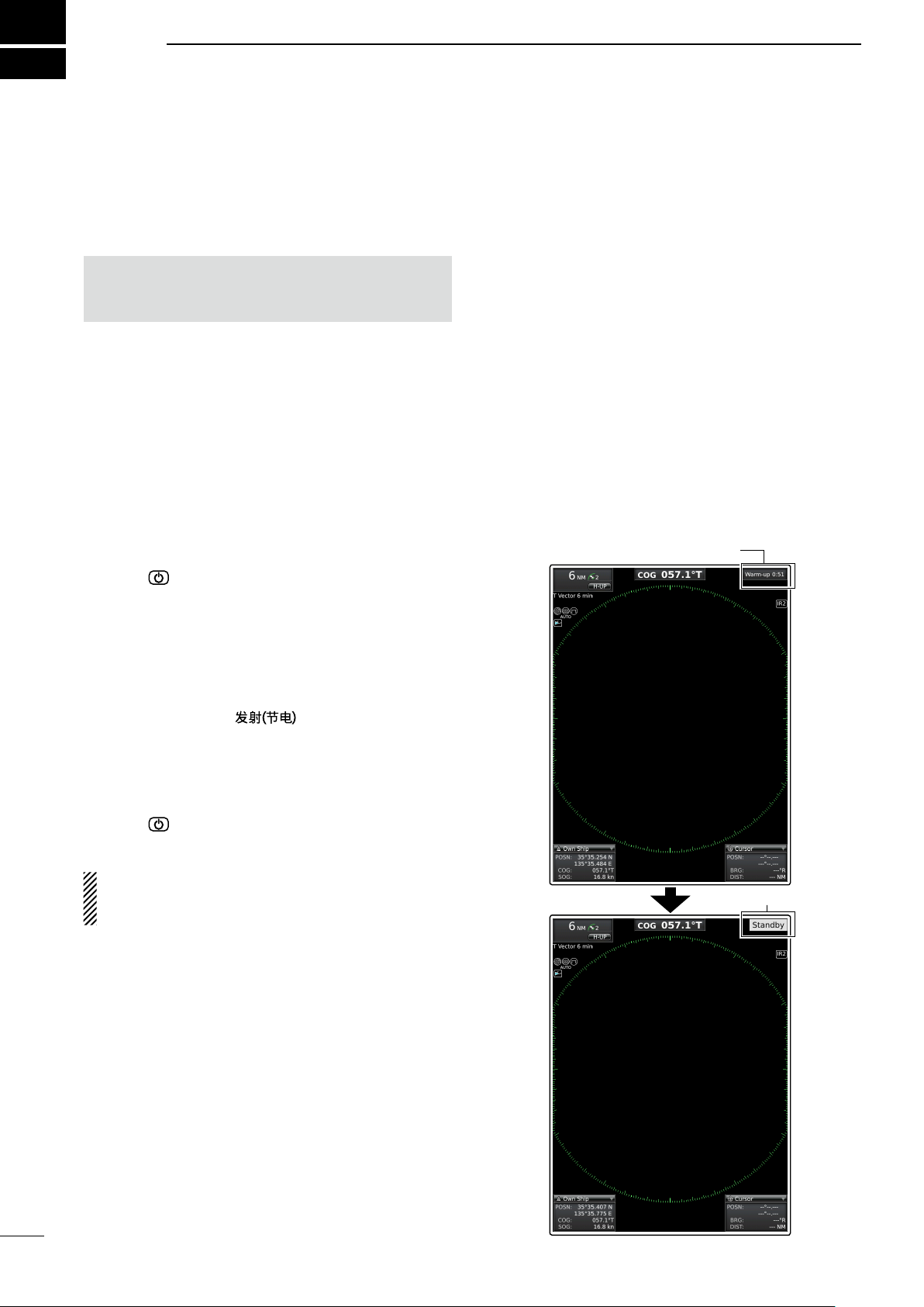
■ Turning power ON/OFF
q Push [ ] to turn ON the power.
• The opening screen is displayed.
• The initial screen is displayed and the magnetron warm
up time is counted down on the screen.
• The magnetron inside the scanner unit warms up for 90
seconds.
w When the countdown is completed, the Standby
screen is displayed.
e Push [TX (SAVE)]/[ ] to start scanning and
select the Plan Position Indicator (PPI) screen.
• Targets and heading markers are displayed.
• The screen is displayed approximately 2 seconds after
turning ON the power, when “Auto” is selected in the
“TUNE” item of the Video menu.
r Push [ ] to turn OFF the power.
D Checklist
q The four bolts securing the scanner unit must be
firmly tightened.
w Cabling must be securely attached to a mast or
mounting material, and must not interfere with the
rigging.
e Be sure waterproofing procedures are completed
on the system cable.
r The power connections to the battery must be of the
correct polarity.
t Be sure that the plugs at the rear of the display unit
have been connected correctly and securely.
(See page 42 for details.)
Warm-up time is displayed
15
At the first turning ON the radar or after executing
Factory Reset, the Initial Setting screen (p. 58) is displayed before the opening screen is displayed.
Standby indicator
Page 21

■ Basic operation
GAIN
SEA
RAIN
TX
SAVE
ENTER
CLEAR
TRAILS
ALM
MODE
OFF CENT
EBL1
VRM1
BRILL
MENU
TLL
HL OFF
EBL2
VRM2
ZOOM
AUTO
ACQ
GAIN
SEA
RAIN
TX
SAVE
AUTO
ENTER CLEAR
MODEMENU
TLL
TRAILS
OFF CENT
ACQ
q Turn ON the power.
w Push [TX (SAVE)]/[ ] on the Standby screen
after the Warm-up is completed.
• See “Turning power ON/OFF” on page 15.
e Push [+]/[ ] one or more times to select the
maximum display range.
r Rotate [GAIN]/[ ] to adjust the gain.
• Clockwise rotation increases the gain.
• The increased gain may increase screen noise.
• Adjust the gain to the point where the screen noise just
disappears.
t Push [+]/[ ] or [–]/[ ] one or more times to
select the desired display range.
•
The screen range readout shows the range of the screen.
y Rotate [SEA]/[ ] to set the sensitivity time
control to minimum.
u Rotate [RAIN]/[ ] to set the rain clutter con-
trol to minimum.
i Push [MODE]/[
up: H-UP, Stabilized head-up: SH-UP, Course-up:
C-UP, North-up: N-UP or True Motion: TM screen.
SH-UP, C-UP, N-UP or TM can be selected only
when bearing or position data is provided.
(See page 63 for details)
] to select either the Head-
BASIC OPERATION
NOTE:
Manual adjustment can be used.
(See below for the Manual Tuning details.)
3
CAUTION: When the SEA setting is set to too high,
close targets are blanked.
D Heading marker
The heading marker is a line that indicates your vessel’s bow direction. (This marker will be displayed on
the center of the screen when the Head-up screen:
H-UP is selected.) You can hide the heading marker
when the desired target is located under the heading
marker.
➥ Simultaneously hold down [BRILL]/[ ] and
[ALM]/[ ] to hide the heading marker.
D Fixed range rings
The fixed range rings can be used for rough distance
measurements. (p. 25)
The Brilliance of the fixed range rings can be adjusted
or turned OFF.
(MENU > Color > Ring Brill)
q Push [MENU]/[ ] to enter the Menu screen.
w Push [t] or [u] to select the Color menu.
e Push [p] or [q] to select the “Ring Brill” item.
• The selected item is highlighted.
r Push [ENTER]/[ ] to enter the option selection
mode.
t Push [p] or [q] to select a desired Ring Brilliance
1, 2, 3 or OFF.
y Push [ENTER]/[ ] to save the setting and exit
the option selection mode.
• Push [CLEAR]/[ ] to cancel the setting and exit the
mode, if desired.
D Manual tuning
The receiver tuning can be manually adjusted.
(MENU > Video > Tune)
q Push [MENU]/[ ] to enter the Menu screen.
w Push [t] or [u] to select the Video menu.
e Push [p] or [q] to select the “TUNE” item.
• The selected item is highlighted.
r Push [ENTER]/[ ] to enter the option selection
mode.
t Push [q] to select “Manual,” then push [ENTER]/
[ ].
• “TUNE (MAN)” is displayed at the top of the screen.
y Push [q] to select the “Manual TUNE” item.
• The selected item is highlighted.
u Push [ENTER]/[ ] to enter the option selection
mode.
• If the “TUNE” item is set to “Auto,” the option selection
mode cannot be entered.
i Push [t] or [u] set the tuning level indicator to the
maximum level. (p. 10)
o Push [ENTER]/[ ].
16
Page 22
3
BASIC OPERATION
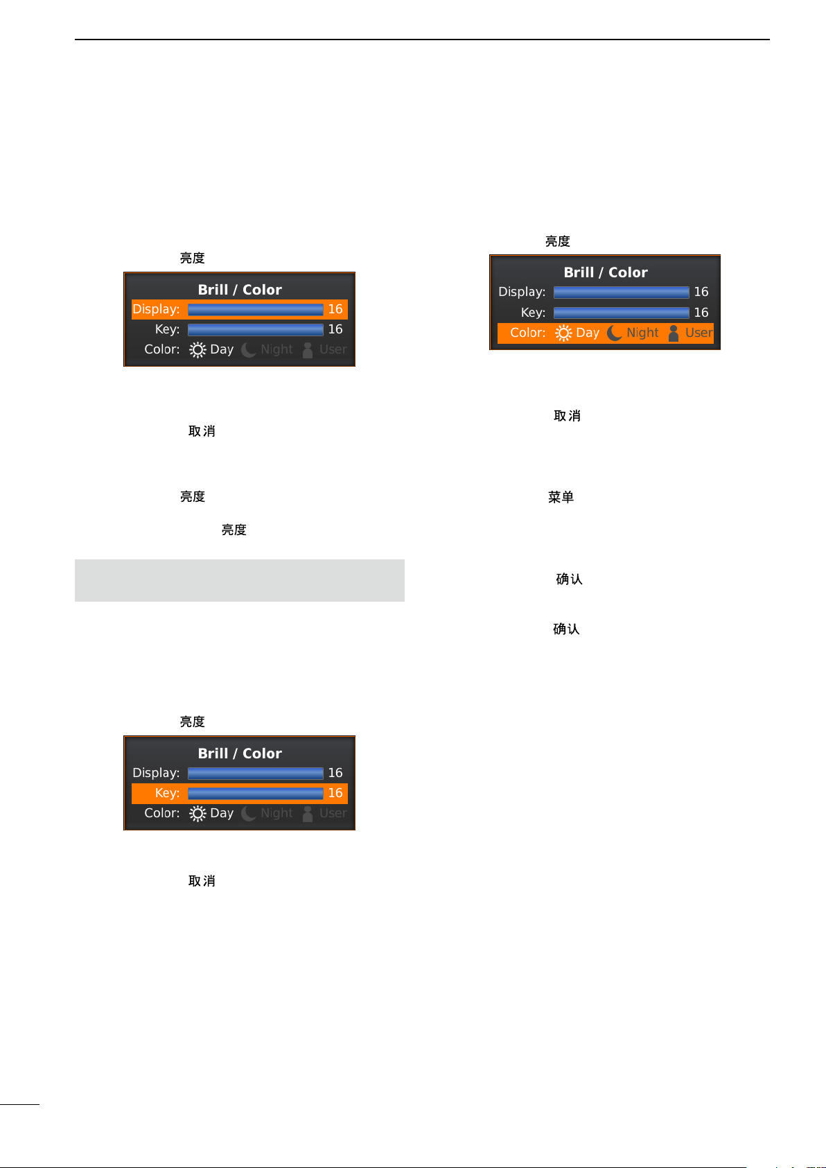
■ Brilliance/Color adjustment
D Adjusting the Display Brilliance
The intensity of the screen can be adjusted. When you
require continuous operation, but not constant viewing, a lower setting can increase the life of the LCD.
q Push [BRILL]/[
w Push [t] or [u] to adjust a desired display brilliance.
• If the other item is selected, push [p] or [q] to select the
“Display” item.
e Push [CLEAR]/[ ] to close the box.
• The display automatically closes the box if you don’t
push any keys for 5 seconds.
➥ Push [BRILL]/[ ] to increase or decrease the dis-
play brilliance.
➥ Hold down [BRILL]/[ ] for 1 second to select
maximum brilliance.
NOTE: High intensity will shorten the life of the LCD
display.
] to open the Brilliance/Color box.
D Selecting the Display color
Three display colors can be memorized and selected
between the Day, Night, and User settings.
q Push [BRILL]/[ ] to open the Brilliance/Color box.
w Push [q] two times to select the “Key” item.
e Push [t] or [u] to set to a desired display color.
• You can set the display color to the Day, Night, or User.
r Push [CLEAR]/[ ] to close the box.
• The display automatically closes the box if you don’t
push any keys for 5 seconds.
• Customizing the Display color
q Push [MENU]/[ ] to enter the Menu screen.
w Push [t] or [u] to select the Color menu.
e Push [p] or [q] to select the “Day Color Setting,”
“Night Color Setting,” or “User Color Setting” item.
• The selected item is highlighted.
r Push [ENTER]/[ ] to enter the option selection
mode.
t Push [p] or [q] to a desired display color, then
push [ENTER]/[ ].
D Adjusting the Key backlight
The backlighting of the keys can be adjusted for convenient operation.
q Push [BRILL]/[ ] to open the Brilliance/Color box.
w Push [q] one time to select the “Key” item.
e Push [t] or [u] to adjust a desired Key illumination.
r Push [CLEAR]/[ ] to close the box.
• The display automatically closes the box if you don’t
push any keys for 5 seconds.
17
Page 23
BASIC OPERATION
Adjust SEA control
Echoes from sea waves
Adjust RAIN controlSmall echoes
The following are typical basic operation examples that may hinder radar reception (sea clutter, precipitation interference and echoes from other radar).
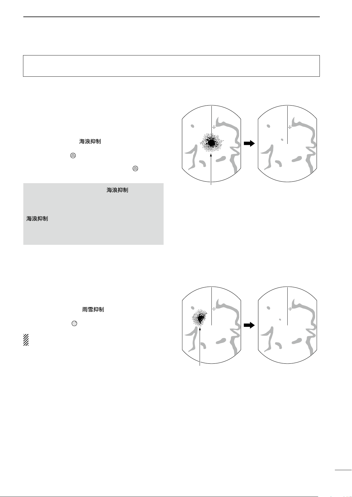
■ SEA function
This function serves to eliminate echoes from waves at
close range. Reduce the receiver gain for close objects
within a radius of approximately 8 NM to eliminate sea
clutter.
3
➥ Rotate the
to activate the automatic control function.
• The SEA icon ( ) is displayed in the upper left corner
of the screen.
• “AUTO” is displayed below the SEA icon (
automatic control function is active.
R WARNING! The [SEA]/[ ] control re-
duces the receiver sensitivity of objects within approximately 8 NM. Therefore, caution and careful
adjustment are necessary when using the [SEA]/[
Small objects may not be displayed on the screen
when strong echoes from rain or islands within 1 NM
while the automatic SEA function is activated.
[SEA]/[ ]
] control.
control fully clockwise
) when the
■ RAIN function
This function eliminates echoes from rain, snow, fog,
and so on.
➥ Rotate the [RAIN]/[ ] control fully counter-
clockwise to deactivate the control function.
• The RAIN icon ( ) disappears.
NOTE: DO NOT reduce the echoes too much, oth-
erwise you may miss weaker targets.
18
Page 24
3
With OFF CENTER ON
Normal screen
With IR function ON
Radar interference
With Echo Stretch ON
Normal screen
BASIC OPERATION
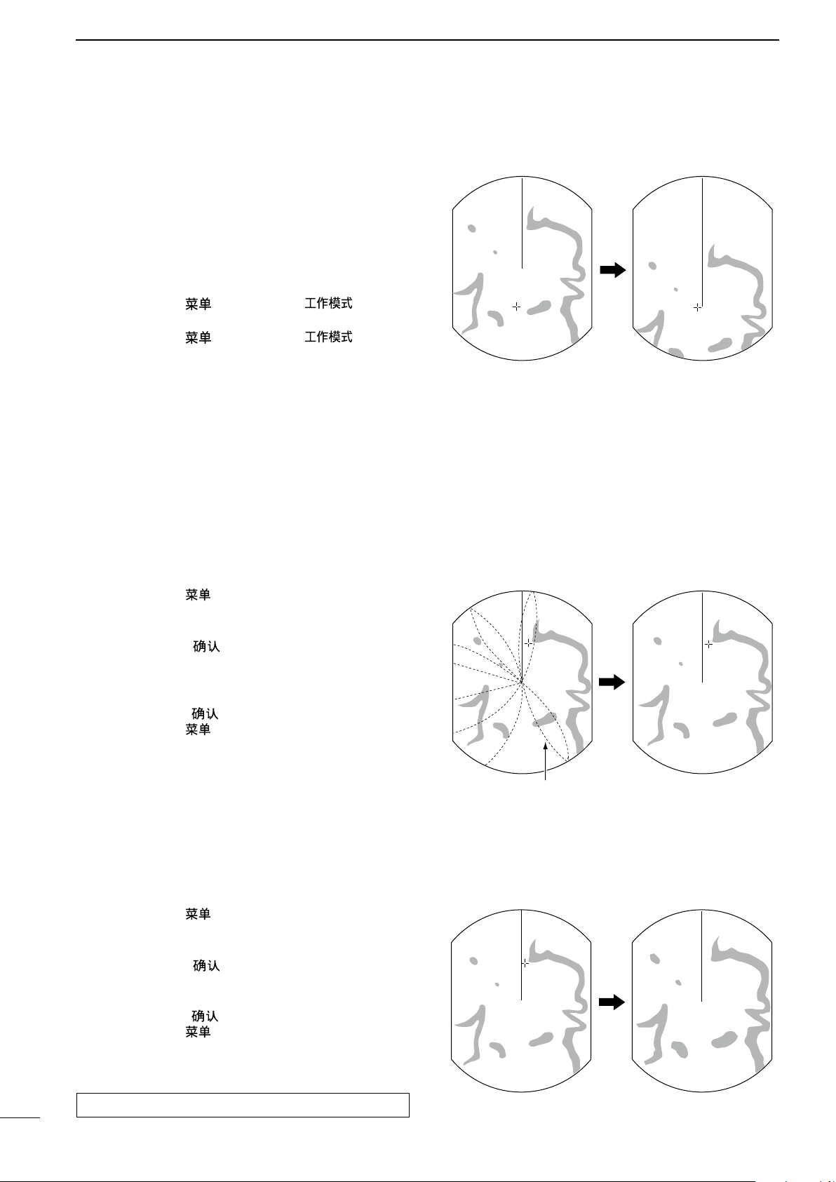
■ OFF CENTER function
The scanning area can be shifted in a desired direction
and can be partially enlarged. This is useful when the
Head-up screen is selected, and you want to enlarge
the bow direction display, or the center of the screen
shifts in the direction of the intersection.
• This function is selectable in 24 NM or shorter ranges.
• This function is not selectable in the TM screen.
q Push [MENU]/[ ] and [MODE]/[ ] simulta-
neously to shift the screen.
w Push [MENU]/[ ] and [MODE]/[ ] simulta-
neously again to return to the normal screen.
The OFF center mode setting can be changed in the
“OFF Center Mode” item of the System menu.
• 25%, 50%, 75%, and Cursor are selectable.
■ IR function
Radar interference may appear when another vessel’s
radar is operating on the same frequency band in close
proximity. The Interference Rejection (IR) function can
eliminate this type of interference. (p. 10)
q Push [MENU]/[ ] to enter the Menu screen.
w Push [t] or [u] to select the Video menu.
e Push [p] or [q] to select the “IR” item.
r Push [ENTER]/[ ] to enter the option selection
mode.
t Push [p] or [q] to select the IR function 1, 2, or
OFF.
y Push [ENTER]/[ ] to save the setting.
u Push [MENU]/[ ] to exit the Menu screen.
• “IR” is displayed in the upper right of the screen,
when the function is activated.
■ Echo Stretch function
The blips can be magnified electronically for easier
viewing of small targets.
(MENU > Video > IR)
(MENU > Video > Echo Stretch)
q Push [MENU]/[ ] to enter the Menu screen.
w Push [t] or [u] to select the Video menu.
e Push [p] or [q] to select the “Echo Stretch” item.
r Push [ENTER]/[ ] to enter the option selection
mode.
t Push [p] or [q] to select the Echo Stretch ON.
y Push [ENTER]/[ ] to save the setting.
u Push [MENU]/[ ] to exit the Menu screen.
• “ES” is displayed in the upper right of the screen, when
the function is activated.
NOTE: Turn OFF this function during normal operation.
19
Page 25

■ Zoom function
With Zoom function ON
Normal screen
The Zoom function expands the target to two times
normal size.
q Push [p], [q], [t], or [u] to move the cursor to the
desired target.
w
Push [EBL1(VRM1)]/[ ] and [EBL2(VRM2)]/
[ ] simultaneously to toggle between the
Zoom function ON and OFF.
• The ZOOM icon ( ) is displayed in the upper right of
the screen.
■ Long pulse function
BASIC OPERATION
3
To magnify the blips for easier viewing of small targets,
the long pulse and echo stretch (p. 19) functions are
usable. When the long pulse is used in the 3⁄4 to 3 NM
range, this function magnifies target echoes behind
the target.
• Pulse selection
q Push [MENU]/[ ], and then push [t] or [u] to
select the Video menu.
w Push [p] or [q] to select the “Pulse Width” item.
e Push [ENTER]/[ ] to enter the option selection
mode.
r Push [p] or [q] to select SP (Short Pulse) or LP
(Long Pulse).
• When “LP” is selected, “ ” is displayed in the upper left
of the screen.
t Push [ENTER]/[ ] to save the setting.
y Push [MENU]/[ ] to exit the Menu screen.
NOTE: Selecting SP (Short Pulse) increases the target distance resolution. (p. 41)
(MENU > Video > Pulse Width)
20
Page 26

3
Trail time
BASIC OPERATION
■ Trail function
The trail function memorizes echoes continuously or
at constant intervals. This is useful for watching other
vessels’ tracks, approximate relative speed, and so on.
D Using the Trail function
q Simultaneously push [ENTER]/[ ] and [CLEAR]/
[ ] to turn ON the Trail function.
• The trail icon and trail interval are displayed in the upper
left of the screen.
• Trail interval counter starts to count up to the trail time.
w All echoes higher than the specified level at the plot-
ted time are memorized and displayed with a graduated intensity together with the current echoes.
• Echoes are displayed with minimum intensity when “∞”
is selected.
• Hold down [ENTER]/[
second to erase the plotted echoes.
e Simultaneously push [ENTER]/[ ] and [CLEAR]/
[ ] to cancel the Trail function and erase the plotted echoes.
• The trail icon and trail interval disappear.
Trail indicator
] and [CLEAR]/[ ] for 1
Trail interval counter
D Customizing the trail settings
You can customize the trail settings in the Trail menu in
the Menu screen.
q Push [MENU]/[ ] to enter the Menu screen.
w Push [t] or [u] to select the Trail menu.
e Push [p] or [q] to select the item.
r Push [ENTER]/[ ] to enter the option selection
mode.
t Push [p] or [q] to select the option.
y Push [ENTER]/[ ] to save the setting.
u Push [MENU]/[ ] to exit the Menu screen.
(MENU > Trail > )
The selectable trail settings are as follows:
Refer to the “Menu screen” section for details on each
item or option. (p. 6)
Reference:
Selects the reference of trails, True for real movement
over ground, and Relative for relative movement to
your vessel.
Time:
Selects the trail time from 30 seconds, 1 minute, 3 minutes, 6 minutes, 15 minutes, 30 minutes, or
Level:
Selects the level of trail from Low, Middle, or High.
Fine Trail:
The Fine trail function makes the trail thin. Selects the
thinness of trails from OFF (normal), 1 (Fine), or 2 (Extra fine).
Color:
Sets the trail color to Blue, Yellow, Green, Red, Orange, or White.
∞.
21
Page 27

■ Power save function
The power save function conserves the boat’s battery power by pausing the transmission. The standby
(pausing) times are selectable (rotation number is
fixed to 10).
For example, when 1 minute is selected, the scanner
rotates 10 revolutions; then stops for 1 minute, and
then repeats this sequence while the power save function is activated.
BASIC OPERATION
3
D Setting the scanning standby time
q Push [MENU]/[ ], and then push [t] or [u] to
select the System menu.
w Push [p] or [q] to select the “Save Time” item.
e Push [ENTER]/[ ] to enter the option selection
mode.
r Push [p] or [q] to select the standby time.
• 1, 6, 15, and 30 minutes are selectable.
t Push [ENTER]/[ ] to save the setting.
y Push [MENU]/[ ] to exit the Menu screen.
D Using the power save function
q Hold down [TX (SAVE)]/[ ] for 1 second to
turn ON the power save function.
• The save indicator is displayed in the upper right of the
screen.
w After the scanning rotations are finished, transmis-
sion and rotation are suspended until the selected
standby time elapses.
• “SAVE” and standby time appear in the upper right of the
screen and the standby time is counted down.
e After the selected standby time elapses, transmis-
sion and rotation restart.
r Push [TX (SAVE)]/[ ] to cancel the power
save function.
• The save indicator turns OFF.
(MENU > System > Save Time)
NOTE: When you use the Power save function together with the Alarm function, the LCD display is
turned OFF until an object enters the programmed
alarm zone, therefore, more power saving is possible.
(p. 29)
Count down
the standby
time
Scan and Standby modes alternate
22
Page 28

3
Identification
Bearing Distance
Position
Time To Go
BASIC OPERATION
■ Ship speed indication
When the ship speed data in NMEA 0183 format is applied, the radar can display the ship speed.
q Push [MENU]/[ ], and then push [t] or [u] to
select the Initial menu.
w Push [p] or [q] to select the “Speed Unit” item.
e Push [ENTER]/[ ] to enter the option selection
mode.
r Push [p] or [q] to select the desired speed unit.
• knot (kn), kilometers/hour (km/h), or miles/hour (mph)
are selectable.
t Push [ENTER]/[ ] to save the setting.
y Push [MENU]/[ ] to exit the Menu screen.
■ Waypoint indication
When waypoint data received from navigation equipment in NMEA 0183 format is applied, the radar can
display the waypoint. To display the waypoint marker,
bearing data and position data are necessary. (p. 63)
(MENU > Initial > Speed Unit)
(MENU > Display > WPT Display)
q Push [MENU]/[ ], and then push [t] or [u] to
select the Display menu.
w Push [p] or [q] to select the “WPT Display” item.
e Push [ENTER]/[ ] to enter the option selection
mode.
r Push [p] or [q] to turn the setting ON or OFF.
t Push [ENTER]/[ ] to save the setting.
y Push [MENU]/[ ] to exit the Menu screen.
D Waypoint information
q Push [t], [u], [p], or [q] to move the “+” cursor on
the waypoint mark or line.
w Push [ENTER]/[ ] to display the information.
• The target identification (ID), position (POSN), Time to
go (TTG), bearing (BRG), and distance (DIST) are displayed.
• To close the information box, move the cursor to the
point where no dotted mark or line is displayed. Then
push [ENTER]/[
].
Waypoint marker
• Waypoint information box
23
Information box:
Move the cursor on the title bar, then push [ENTER]/
[ ] to collapse or expand the information box.
Page 29

BASIC OPERATION
3
■ Bearing setting
The radar bearing interface accepts NMEA, N+1, AUX,
or COG data format and the bearing can use a magnetic or true north type. When a true north type bearing is used, the variation from magnetic north can be
adjusted on 0.1˚ steps.
D Setting the bearing type
q Push [MENU]/[ ], and then push [t] or [u] to
select the System menu.
w Push [p] or [q] to select the “Bearing Mode” item.
e Push [ENTER]/[ ] to enter the option selection
mode.
r Push [p] or [q] to select the Bearing mode.
• True and Magnetic north type are selectable.
• All displayed bearing readouts show the selected bearing type.
t Push [ENTER]/[ ] to save the setting.
y Push [MENU]/[ ] to exit the Menu screen.
D Setting the magnetic variation
q Push [MENU]/[ ], and then push [t] or [u] to
select the System menu.
w Push [p] or [q] to select the “Variation” item.
e Push [ENTER]/[
mode.
r Push [p] or [q] to select the bearing variation.
• “Auto”* and “Manual” are selectable.
t Push [ENTER]/[ ] to save the setting.
y When the “Manual” option is selected in step r,
push [q] to select the “Manual Variation,” then push
[ENTER]/[ ].
u Push [p] or [q] to set the bearing variation.
i Push [ENTER]/[ ] to save the setting.
o Push [MENU]/[ ] to exit the Menu screen.
] to enter the option selection
(MENU > System > Bearing Mode)
T: True north
M: Magnetic north
(MENU > System > Variation)
* NOTE:
• NMEA data is required for the Auto variation. NEV-
ER select “Auto” without NMEA data or incorrect
variation data may be entered.
• Until an effective variation is received, use 0° for
difference between true North and magnetic North.
After an effective variation is received, use the last
data for the difference. The MR-1210 memorize
the data until you turn OFF the power.
24
Page 30

4
DISTANCE AND DIRECTION MEASUREMENTS
■ Distance measurement
Various way to measure the distance are provided with this radar.
•
The distance unit, nautical miles (NM), kilometers (kn), or miles (SM) is selected in the Initial menu of the Menu screen (p. 12).
TYPE DESCRIPTION
Fixed range rings
(RING)
Parallel index lines
(PI)
Variable range marker 1
(VRM1)
Variable range marker 2
(VRM2)
Displays fixed rings.
Suitable for rough estimations from your own vessel to any target.
Selectable from two types of range rings.
Displays six parallel index lines.
Suitable for rough estimations from your own vessel to any target.
Displays a variable range marker and activated by [p] or [q] for the range marker selector.
Suitable for accurate measurements from your own vessel to a target.
Normally functions the same as VRM1. When the VRM1 and EBL1 selects a target, the center
of VRM2 is displayed at the intersection point.
Suitable for accurate measurements from target to target.
D Setting the Fixed range rings brilliance
(MENU > Color > Ring Brill)
q Push [MENU]/[ ], and then push [t] or [u] to
select the Color menu.
w Push [p] or [q] to select the “Ring Brill” item.
e Push [ENTER]/[ ] to enter the option selection
mode.
r Push [p] or [q] to select the desired brilliance (1
to 3) to turn ON the Ring function and display the
fixed rings.
• 1 to 3 and OFF are selectable.
• The ring range is fixed depending on the screen range.
(See the tables below.)
t Push [ENTER]/[ ] to save the setting.
y Push [MENU]/[ ] to exit the Menu screen.
To clear the fixed rings, select “OFF” in step e
above.
Ring range
Fixed
range rings
D Selecting the range ring type
(MENU > Initial > Range Ring)
q Push [MENU]/[ ], and then push [t] or [u] to
select the Initial menu.
w Push [p] or [q] to select the “Range Ring” item.
e Push [ENTER]/[ ] to enter the option selection
mode.
r Push [p] or [q] to select the type of the fixed range
rings Ring1 or Ring2.
• The ring range is fixed depending on the screen range.
(See the tables below.)
t Push [ENTER]/[ ] to save the setting.
y Push [MENU]/[ ] to exit the Menu screen.
• Fixed rings in each screen range
Range
Ring range
(NM)
1
1
1
3
1 0.25 4 1.5 0.5 0.25 3 6
1.5 0.5 0.25 3 6 2 0.5 4
2 0.5 4 3 1 0.5 3 6
3 1 0.5 3 6 4 1 4
4 1 4 6 2 1 3 6
6 2 1 3 6 8 2 4
8 2 4 12 3 4
12 3 2 4 6 16 4 4
16 4 4 24 6 4
24 6 4 4 6 32 8 4
32 8 4 36 12 3
36 12 3 48 12 4
48
64
72
(NM)
Ring1 Ring2 Ring1 Ring2
⁄
0.0625 2
8
⁄
0.125 2
4
⁄
0.125 4
2
⁄
0.25 3 1 0.25 4
4
*1
12 4 64
*1
16 4 72
*2
18 4 96
*1 Available for MR-1210TII and MR-1210TIII only.
2
*
Available for MR-1210TIII only.
NOTE: When the screen is shifted, the number of rings
may differ.
Number
of rings
Range
Ring range
(km)
1
1
3
(km)
Ring1 Ring2 Ring1 Ring2
⁄
0.125 2
4
⁄
0.125
2
⁄
0.25 3
4
*1
*1
*2
16 4
18 4
24 4
Number
of rings
0.25 4 2
25
Page 31

DISTANCE AND DIRECTION MEASUREMENTS
4
D Using the Parallel index lines
q Simultaneously hold down [EBL1(VRM1)]/
[ ] and [EBL2(VRM2)]/[ ]
for 1 second to display the Parallel index lines.
• The crossed lines are displayed.
w Push [p] or [q] to increase or decrease the range
of lines, and [t] or [u] to rotate the lines.
• The direction of the parallel index lines and the range of
lines are displayed on the lower right of the screen.
e Push [ENTER]/[ ] to set lines.
r Simultaneously hold down [EBL1(VRM1)]/
[ ] and [EBL2(VRM2)]/[ ]
for 1 second to clear the parallel index lines.
Parallel
Index lines
D Using the variable range marker
q Push [EBL1 (VRM1)]/[ ] to display the
VRM1 and EBL1; then push [p] or [q] to set the
marker.
• The range between the vessel and the target is indicated
in the EBL/VRM1 readout
w Push [ENTER]/[ ] to set the EBL/VRM1 setting.
e Push [EBL2 (VRM2)]/[ ] to display the
VRM2 and EBL2; then push [p] or [q] to set the
marker.
• The range between the vessel and the target is
indicated in the EBL/VRM2 readout.
• When VRM1 and EBL1 are displayed, the cen-
ter of VRM2 appears at the intersection point of
VRM1 and EBL1.
r Push [ENTER]/[ ] to set the EBL/VRM2 setting.
t Push [EBL1 (VRM1)]/[ ] to clear the
EBL1 and VRM1.
y Push [EBL2 (VRM2)]/[ ] to clear the
EBL2 and VRM2.
Parallel
Index line
readout
26
Page 32

4
DISTANCE AND DIRECTION MEASUREMENTS
■ Bearing and Distance measurement
This radar has two Electronic Bearing Lines (EBL) to
indicate the target direction from your ship or a target.
D Using both the EBL and VRM
q Push [p], [q], [t], or [u] to move the cursor onto
the desired target.
w Push [EBL1 (VRM1)]/[ ] to display the
EBL1 and VRM1.
• Push [t] or [u] to rotate the Electronic Bearing Line.
• Push [p] or [q] to increase or decrease the Variable
Range Marker’s ring size.
• The EBL/VRM1 readout indicates the target bearing and
distance.
• The EBL readouts indicate the target bearing.
The indication may differ, depending on the setting in the
“Bearing Reference” item of the System menu (p. 12).
0 to 360°R: Relative direction, when “360°R” is se-
lected in the “Bearing Reference” item.
P/S 0 to 180°: Bow direction, when “PT/SB” is selected
in the “Bearing Reference” item.
0 to 360°T*: True or magnetic bearing, when selecting
“True” in the “Bearing Reference” item.
*Bearing data is required. (p. 63)
e Push [ENTER]/[ ] to set the EBL/VRM1 setting.
r Push [p], [q], [t], or [u] to move the cursor onto
the desired target.
t Hold down [EBL1 (VRM1)]/
ond to move the EBL1 and VRM1 to the cursor.
• Hold down [EBL1 (VRM1)]/
again to move the EBL1 and VRM1 to the original place.
y Push [EBL1 (VRM1)]/[ ] to clear the
EBL1 and VRM1.
• The cursor remains on the display.
[ ]
[ ]
for 1sec-
for 1second
EBL1
VRM1
EBL/VRM1
readout
EBL1
VRM1
EBL/VRM1
readout
27
■ Advanced measurements
Using both Electronic Bearing Lines (EBL) and both Variable Range Markers (VRM), the following advanced measurements can be made.
D Measuring the distance and direction between two targets
q Push [p], [q], [t], or [u] to move the cursor onto
the desired target.
w Push [EBL1 (VRM1)]/[ ] to display the
EBL1 and VRM1.
• Push [t] or [u] to rotate the Electronic Bearing Line.
• Push [p] or [q] to increase or decrease the Variable
Range Marker ring size.
e Push [ENTER]/[ ] to set the VRM/EBL1 setting.
r Push [EBL2 (VRM2)]/
[ ]
to display the
EBL2 and VRM2.
• The intersection of the EBL1 and VRM1 becomes the
center of the EBL2 and VRM2.
t Push [p], [q], [t], or [u] to move the cursor onto
the other target.
• Push [t] or [u] to rotate the Electronic Bearing Line.
• Push [p] or [q] to increase or decrease the Variable
Range Marker ring size.
y The VRM2 readout displays the distance between
the two targets. The EBL2 readout displays the direction from one target to the other.
VRM1
EBL1
EBL2
VRM2
Page 33

DISTANCE AND DIRECTION MEASUREMENTS
D Measuring the relative speed and course of a target
4
q Simultaneously push [ENTER]/[
] and [CLEAR]/
[ ] to turn ON the Trail function, and then the trail
extends until it reaches to the preset trail time. (pp.
6, 21)
• The trail icon and trail interval are displayed in the upper
left of the screen.
w Push [EBL1 (VRM1)]/[ ] to display the
EBL1 and VRM1, and then set the VRM1 and EBL1
to a previously plotted target.
• Push [t] or [u] to rotate the Electronic Bearing Line.
• Push [p] or [q] to increase or decrease the Variable
Range Marker ring size.
e Push [ENTER]/[ ] to set the VRM1/EBL1 setting.
r Push [EBL2 (VRM2)]/
[ ]
to display the
EBL2 and VRM2, and then set the VRM2 and EBL2
to the current plotted position of the same target.
• The intersection of the EBL1 and VRM1 becomes the
center of the EBL2 and VRM2.
t The VRM2 is a measure of target movement that
can be converted into relative target speed.
• For example, when a 6 minute trail time is selected, mul-
tiplying the distance by ten gives the relative average
speed of the target.
• If your vessel is stationary during the plotting time, the
converted speed and direction become absolute.
• The converted speed unit is knots, kilometers or miles,
depending on the Distance Unit in the Initial menu.
y The EBL2 displays the course direction of the target.
VRM1
EBL1
EBL2
VRM2
D Measuring the distance and course from a waypoint
q Display a waypoint as described on page 23.
w Push [EBL1 (VRM1)]/[ ] to display the
EBL1 and VRM1, and then set the VRM1 and EBL1
to the waypoint.
• Push [t] or [u] to rotate the Electronic Bearing Line.
• Push [p] or [q] to increase or decrease the Variable
Range Marker ring size.
e Push [ENTER]/[ ] to set the VRM1/EBL1 setting.
r Push [EBL2 (VRM2)]/
EBL2 and VRM2, and then set the VRM2 and EBL2
to a target point.
(Example: Set to the next waypoint.)
• The intersection of the EBL1 and VRM1 becomes the
center of the EBL2 and VRM2.
t The VRM2 displays the distance to the target from
the first waypoint.
• The distance unit can be selected as nautical miles (NM),
kilometers (km) or Sea miles (SM) in the Initial menu.
y The EBL2 readout displays the direction to the tar-
get from the first waypoint.
[ ]
to display the
EBL2
VRM2
VRM1
EBL1
28
Page 34

5
The unit has an alarm function to protect your vessel from collisions. If other vessels, islands or other obstructions
come into the preset alarm zone, the function alerts you with an alarm. You can set the desired range and bearing
for up to two alarm zones. While the alarm function is activated, the power save function turns OFF the LCD screen
until an alarm is given, to conserve the power.
ALARM FUNCTION
■ Setting Alarm zone
D Setting and using the alarm function
q Push [+]/[ ] or [–]/[ ] to select a desired
range.
w Push [t], [u], [p], or [q] to set the cursor to the
starting point of the alarm zone.
e Push [ALM]/[ ] several times to turn ON the de-
sired functions, Alarm 1 or Alarm 2.
•
“ ” and the preset alarm zone(s) is displayed. (Fig. 1)
e Hold down [ALM]/[ ] for 1 second to enter the
alarm zone setting.
• The starting zone is displayed on the screen. (Fig. 1)
r Push [t] or [u] to adjust an angle and push [p] or
[q] to set the distance of the alarm zone.
• The selected alarm zone is displayed.
t Push [ALM]/[ ] to set the alarm zone and acti-
vate the alarm function.
•
“ ”
is displayed on the upper right of the screen.
• The selected alarm zone remains.
y If a target comes into or goes out of the alarm zone,
an alarm sounds.
• Push [CLEAR]/[ ] to stop the alarm, or push [ALM]/
[
] to cancel the alarm signal and function.
u To deactivate the alarm function, push [ALM]/
[ ] several times.
•
“ ”
and alarm zone disappear.
i To activate the alarm function again with the same
programmed zone, push [ALM]/[ ].
•
“ ” and the preset alarm zone are displayed. (Fig. 2)
Push [t], [u], [p] or [q], then Push
[ALM]/[
]
Alarm icon is
displayed
Fig. 1
29
If “ ” is displayed, the alarm function is invalid. In
that case, push [+]/[ ] until the alarm icon returns to
“ .”
D Entering the power save mode
➥ To activate the power save function, hold down
[TX (SAVE)]/[ ] for 1 second while the
Alarm function is ON.
• The power save function is activated and the display
turns OFF.
• When a target comes into the alarm zone, an alarm
sounds, the display turns ON and the power save mode
is cancelled.
Fig. 2
Page 35

Alarm sounds when the target
comes into the zone.
Alarm zone
Target (other ship, and so on)
■ Setting Zone alarm type
ALARM FUNCTION
5
A zone alarm sounds when the target comes into the
zone, or when the target goes out of the zone. (p. 11)
q Push [MENU]/[ ], and then push [t] or [u] to
select the System menu.
w Push [p] or [q] to select the “Zone Alarm1” or “Zone
Alarm2” item.
e Push [ENTER]/[ ] to enter the option selection
mode.
r Push [p] or [q] to select IN or OUT.
• IN: Alarm sounds when the target comes into the
zone.
• OUT: Alarm sounds when the target goes out of the
zone.
t Push [ENTER]/[ ] to save the setting.
y Push [MENU]/[ ] to exit the Menu screen.
(MENU > System > Zone Alarm1)
(MENU > System > Zone Alarm2)
30
Page 36

6
ATA OPERATION
■ ATA (Automatic Tracking Aid)
By automatically tracking the target chosen with the cursor key, the closest point of approach (CPA) and the time
to closest point of approach (TCPA) limit of your vessel and a target are calculated.
ATA function is designed to sound an alarm when the CPA and TCPA fall below a set value (the approach watch
area).
Only targets in the 0.25 to 16 NM range that are displayed with a high luminosity (strong return signal) can be
selected as ATA targets.
• A maximum of 10 targets can be plotted on the screen.
• Plot positions are identified by an approved symbol mark (p. 33) and associated plot number.
• The target and vector line will move across the screen at the rate and direction defined by the calculated true
or relative course and speed.
• The vector line is displayed on the target.
■ The ATA function ON or OFF
q Push [MENU]/[ ] to enter the Menu screen.
w Push [t] or [u] to select the ATA menu.
e Push [p] or [q] to select the “Function” item.
r Push [ENTER]/[ ] to enter the option selection
mode.
t Push [p] or [q] to select “ON” or “OFF” to turn the
ATA function ON or OFF.
y Push [ENTER]/[ ] to save the setting.
u Push [MENU]/[ ] to exit the Menu screen.
■ ATA settings
Set the menu items before using the ATA function.
q Push [MENU]/[
select the ATA menu.
w Push [p] or [q] to select the item.
e Push [ENTER]/[ ] to enter the option selection
mode.
r Push [p] or [q] to select an option.
t Push [ENTER]/[ ] to save the setting.
y Push [MENU]/[ ] to exit the Menu screen.
], and then push [t] or [u] to
(MENU > ATA > Function)
(MENU > ATA >)
31
D Track
The plot displays the target’s past positions as 5 dots,
during each specified tracking interval.
You can specify the track interval in the “Track Interval”
item of the Target menu.
• OFF: Turns OFF the Track display function.
• ON: Turns ON the Track display function.
D No. Display
Selects the target identification number type that is
displayed at the right side of the mark.
• OFF: Does not display any mark number.
• Select: Displays only the selected mark number.
• All: Displays all mark numbers.
Page 37

■ Related settings
Identification No.Vector mode
Bearing
Course
Distance
Speed
Position
Time to Closest Point of Approach
Closest Point of Approach
D Target menu
You can change the target settings for ATA operation.
The settings of the Target menu are commonly used
for the ATA and AIS operations. See page 7 for the
Target menu details.
These are the Target menu items and their default settings.
• Vector Mode: True
• Vector Time: 6 min
• Track Interval: 1 min
• CPA* Limit: 1.0 NM
• TCPA* Limit: 1 min
• CPA/TCPA Alarm: ON
■ ATA operation
ATA OPERATION
* CPA/TCPA: Closest Point of Approach and Time to
Closest Point of Approach limits are set to give a
warning when a target or targets enter those limits
around your own vessel.
6
D Operation
Select a target on the screen that you want to track.
Turn ON the ATA function and set its settings. (p. 31)
q Push [p], [q], [t] or [u] to move the “+” cursor onto
a desired target.
w Hold down [MODE•ACQ]/[ • ] for 1 sec-
ond to set the target for tracking.
• A dotted circle symbol is displayed on the cursor.
• After 20 seconds progressing time has passed, the dotted vector is displayed on the target.
• After 1 minute progressing time has passed, it changes
to a solid circle with a dotted vector line, and tracking
operation starts.
➥ When the target disappears, red crosses blink on
the target, and then the mark disappears after 1
minute.
➥ When a target advances within the CPA and TCPA
limits, the mark changes its color to red, blinks, and
sounds an alarm. To cancel the alarm, push any
key.
➥ To cancel the target setting, move the cursor onto
the target, then hold down [CLEAR]/[ ] for 1 second.
➥ To select the target that displays information, set the
cursor to the target, and then push [ENTER]/[ ].
• The corners of a square are displayed on the selected
target.
• The target identification number, position (POSN), course
(CRS), speed (SPD), CPA, TCPA, bearing (BRG), and
distance (DIST) are displayed.
• ATA information box
Information box:
Move the cursor on the title bar, then push [ENTER]/
[ ] to collapse or expand the information box.
32
Page 38

6
Vector
Current position
Vector time
Target’s predicted
positon
Going straight Tu rning right Decelerating Accelerating
ATA OPERATION
■ ATA operation (Continued)
D All Clear Target
Releases all of the ATA targets at the same time.
q Push [MENU]/[ ], and then push [t] or [u] to
select the ATA menu.
w Push [p] or [q] to select the “All Clear Target”
item.
e Push [ENTER]/[ ].
• The dialog box “Sure?” is displayed.
r Push [ENTER]/[ ] again to release all ATA tar-
gets.
• The “All Clear Target” item is grayed out.
t Push [MENU]/[ ] to exit the Menu screen.
■ Plotting marks
There are 5 kinds of plotting marks.
Mark Description
(MENU > ATA > All Clear Target)
Selected, uncalculated mark.
Selected, calculated mark.
Normal, calculated mark.
CPA/TCPA alarm mark.
The target is close to within a minimum range and time.
• Alarm sounds and red colored mark blinks.
Push any key to cancel the alarm.
Indicates the tracking of a target disappears.
• Alarm sounds and red crosses blink.
Push any key to cancel the alarm.
■ Course and speed vector
The vector indicates the target’s predicted, true or relative course and speed.
• The vector time may change, depending on the setting in
the “Vector Time” item of the Target menu (p. 7).
• The tip of the vector shows the target’s predicted position
after the time selected in the “Vector Time” item of the Target menu (p. 7).
■ Plots (ATA)
The plot displays the target’s past positions as 5 dots,
during each specified tracking interval.
• The target track interval may change, depending on the setting in the “Track Interval” item of the Target menu (p. 7)
33
Page 39

AIS OPERATION
7
■ AIS (Automatic Identification System)
AIS is an acronym for “Automatic Identification System.”
An AIS transponder is a short range data radio unit, used primarily for collision-risk management and navigation
safety. It automatically transmits and receives vessel information such as the vessel name, MMSI code, vessel
type, position data, speed, course, destination and more. Information is exchanged among the vessels and/or
base stations on the VHF maritime mobile band. The information helps to identify other nearby vessels or stations
by displaying the received data on the radar screen.
■ The AIS Display ON or OFF
q Push [MENU]/[ ] to enter the Menu screen.
w Push [t] or [u] to select the AIS menu.
e Push [p] or [q] to select the “Display” item.
r Push [ENTER]/[ ] to enter the option selection
mode.
t Push [p] or [q] to select “ON” or “OFF” to turn the
AIS display ON or OFF.
y Push [ENTER]/[ ] to save the setting.
u Push [MENU]/[ ] to exit the Menu screen.
■ AIS settings
Sets the menu items before using the AIS function.
q Push [MENU]/[
select the AIS menu.
w Push [p] or [q] to select the item.
e Push [ENTER]/[ ] to enter the option selection
mode.
r Push [p] or [q] to select an option.
t Push [ENTER]/[ ] to save the setting.
y Push [MENU]/[ ] to exit the Menu screen.
], and then push [t] or [u] to
(MENU > AIS > Display)
(MENU > AIS >)
D Track
The plot displays the AIS target’s past positions as 5
dots, during each specified tracking interval.
You can set the track interval in the “Track Interval”
item in the Target menu.
• OFF: Turns OFF the Track display function.
• ON: Turns ON the Track display function.
D Name Display
Selects the AIS target display type.
• OFF: Does not display any name or number
of the target.
• Select: Displays the vessel name of the selected target.
• Active: Displays all active target numbers.
D Auto Activate
The Auto Activate function automatically turns the
sleeping AIS target into an activated target when the
AIS target is at the specified distance or angle.
You can specify the distance or angle in the next two
items.
• OFF: Turns OFF the Auto Activate function.
• ON: Turns ON the Auto Activate function.
D Auto Activate - Distance
Sets the distance to automatically turn the sleeping
AIS target into an activated target.
• 0.1 to 10.0 NM:
Select the distance from your vessel.
34
Page 40

7
AIS OPERATION
■ AIS Setting (Continued)
D Auto Activate - Angle
Sets the angle to automatically turn the sleeping AIS
target into an activated target.
• 5 to 180°: Selects the angle from your vessel.
D New Target Warning
Sets whether or not to alert when the Auto Activate
function automatically turns the sleeping AIS target
into an activated target.
• OFF: Does not give a warning when the Auto Activate function activates the target.
• ON: Gives a warning when the Auto Activate function activates the target.
D Number of AIS
Selects the maximum number of AIS targets that can
be displayed on the screen to between 10 and 100 in
1 target steps.
D Safety Message
Sets whether or not to display the message when the
safety message is received.
• OFF: Turns OFF the Safety Message function.
• ON: Turns ON the Safety Message function.
D Favorite AIS
Sets whether or not to alert that the specified MMSI
target gets into the specified range from your vessel,
or not.
• OFF: Turns OFF the Favorite AIS function.
• ON: Turns ON the Favorite AIS function.
D Favorite AIS Range
Sets the Favorite AIS display range to between 0.1
and 36.0 NM.
• 0.1 to 36.0 NM: Selects the range from your vessel in
0.1 NM steps.
D Slow Warn
The AIS unit calculated COG (Course Over Ground)
data of a vessel that is at anchor or drifting is unreliable, and therefore the CPA (Closest Point of Approach) and TCPA (Time to CPA) data may not be
correctly calculated. If a vessel is anchored in your
alarm zone, the unreliable data can cause the collision
alarm to sound many times, even if there is no real
danger. To prevent this, when the anchored vessel’s
SOG (Speed Over Ground) is less than this set value,
the Slow Warn function assumes that vessel’s COG is
fixed towards your vessel and an alarm will sound.
• OFF: Turns OFF the Slow Warn function.
• ON: Turns ON the Slow Warn function.
D Slow Warn Speed
• 0.1 to 5.0 kn: Selects the vessel’s speed in 0.1 kn
steps.
D Erase Lost Target
Erases all of the Lost targets at the same time.
When there is no lost target, this setting grays out.
q Push [ENTER]/[ ].
• The dialog box “Sure?” is displayed.
w Push [ENTER]/[ ] again to clear all of the Lost
targets on the screen.
About “Lost Target”: A vessel is regarded as a “Lost
target” after a specified period of time has passed
since the vessel last transmitted data, as described on
page 9.
The “Lost target” icon disappears from the screen 6
minutes and 40 seconds after the vessel was regarded
as a “Lost target.”
D Favorite AIS Target1
D Favorite AIS Target2
D Favorite AIS Target3
Enters the MMSI number of favorite targets.
■ Related settings
D Target menu
You can change the target settings for AIS operation.
The settings of the Target menu are commonly used
for the ATA and AIS operations. See page 7 for the
Target menu details.
These are the Target menu items and their default settings.
• Vector Mode: True
• Vector Time: 6 min
• Track Interval: 1 min
• CPA* Limit: 1.0 NM
• TCPA* Limit: 1 min
• CPA/TCPA Alarm: ON
* CPA/TCPA: Closest Point of Approach and Time to
Closest Point of Approach limits are set to give a
warning when a target or targets enter those limits
around your own vessel.
35
Page 41

■ Description of the AIS display
AIS target
The AIS targets are displayed with the icons described
below.
Icon Description
Vessel
The tip of the target triangle automatically points in
the direction it’s heading.
Base Station
Search and Rescue (SAR)
Aids to Navigation (AtoN)
Virtual Aids to Navigation (Virtual AtoN)
Search and Rescue Transponder (SART), MAN
OVERBOARD (MOB), or Emergency Position Indicate Radio Beacon (EPIRB)
AIS icon
AIS OPERATION
AIS target
7
Selected AIS target
The corners of a square are displayed when a target is
selected. The information of the selected AIS target is
displayed in the AIS box.
AIS icon
Displayed when a valid VDM sentence is input from
the [NMEA1] (AIS) port.
The indicator disappears if the AIS signal is not received for 6 minutes.
Your vessel icon
Your vessel icon is displayed in the center of the standby screen when a valid VDM sentence is input from the
[NMEA1] (AIS) port.
• The icon is displayed when “AIS” is selected in the
“STBY Mode” item of the System menu (p. 12).
Selected AIS target
AIS information
If more than the specified AIS signals are received,
“R AIS Data is Full” is displayed.
The number of AIS signals are specified in the “Number of AIS” item of the AIS menu.
36
Page 42

7
AIS classes/Target typeMMSI number
Vector mode
Bearing
Course
Distance
Speed
Vessel name
Time to Closest Point of Approach
Closest Point of Approach
Detail
AIS OPERATION
■ AIS operation
D Operation
Select a target whose information you want to display
on the screen.
Turn ON the AIS display and set its settings. (pp. 34,
35)
q Push [p], [q], [t] or [u] to move the “+” cursor onto
a desired target.
w Push [ENTER]/[ ] to select the target.
• The corners of a square is displayed on the selected
target.
• The target information is displayed in the AIS information
box.
- AIS Class, MMSI number, Vessel name, Course
(CRS), Speed (SPD), CPA, TCPA, bearing
(BRG), and distance (DIST) are displayed.
➥ If several targets are overlapped on the screen,
push [ENTER]/[ ] to sequentially select a target.
➥ When the sleeping target is selected, hold down
[ENTER]/[ ] for 1 second to manually change the
selected target to activated.
➥ When the activated target is selected, hold down
[CLEAR]/[ ] for 1 second to change the selected
target to sleeping.
➥ When the target disappears, red crosses blink on
the target, and then the mark disappears after 6
minutes and 40 seconds.
➥ When a target advances within the CPA and TCPA
limits, mark changes its color to red, blinks, and
sounds an alarm. To cancel the alarm, push any
key.
➥ When the cursor onto the “ ” (detail) icon, push
[ENTER]/[ ] to open the Detail window.
• Push [p], [q] to scroll the window.
• Push [CLEAR]/[
] to close the window.
• AIS information box
Information box:
Move the cursor on the title bar, then push [ENTER]/
[ ] to collapse or expand the information box.
37
Page 43

■ Status of the vessel icon
Going straight Tu rning right Decelerating Accelerating
There are 5 kinds of target vessel status.
Sleeping target:
The AIS signal has been updated (received),
but the distance from your vessel is far, or you
set it as ‘sleeping.’ The target is displayed as
just a triangle without a heading or vector line.
AIS OPERATION
7
Activated target:
The target is displayed with the heading line,
SOG (Speed Over Ground), COG (Course
Over Ground) vector and ROT (Rate of Turn).
Dangerous target:
Selected target:
The target information is displayed in the AIS
Lost target*:
When the AIS signal has not been updated
If the AIS signal has still not been updated (re-
* A vessel is regarded as a “Lost target” after a specified pe-
riod of time has passed since the vessel last transmitted
data. (p. 9)
Even if the target’s status is sleeping or activated, when it enters your CPA and TCPA limit
settings, the target is displayed with a thick line
and changes its color to red.
information box.
(received) for a specific time period, the target
triangle is marked with a red cross.
ceived) for 6 minutes and 40 seconds, the target icon disappears.
• Activated target
SOG (Speed Over Ground) and
COG (Course Over Ground) vector
ROT (Rate of Turn)
Heading line
If there is no heading data, the line points
in the direction of the COG.
➥ When the sleeping target is selected, hold down
[ENTER]/[ ] for 1 second to manually change
the selected target to activated.
➥ When the activated target is selected, hold down
[CLEAR]/[ ] for 1 second to change the selected target to sleeping.
■ Plots (AIS)
The plot displays the activated target, SAR, SART,
MOB, or EPIRB’s past positions as 5 dots, during each
specified tracking interval.
• The target track may change, depending on the setting in
the “Track Interval” item of the Target menu. (p. 7)
38
Page 44

Target
Scanner
Mast or
similar obstruction
An echo is reflected at this point.
Your ship
Target
Bridge
Tr ue echo
False echo
Indirect echo
Tr ue echo
Main beam
Sidelobes
False
echoes
Tr ue
echo
8
Radar uses a form of electromagnetic radiation that can be reflected off a large vessel, bridge, or other metal objects that are in proximity. Because of this property, unwanted reflections off some objects may cause false echoes
to appear on the screen where in fact no actual targets exist. Operators should be familiar with the effect of this
phenomena. In some cases, echoes can be reduced.
BASIC RADAR THEORY
■ Sidelobe echoes
Radiation can escape on each side of the beam inside
the sidelobes. If a target reflects this radiation, it will be
displayed on the screen as an echo.
■ Indirect echoes
Indirect echoes may be returned from either a passing
vessel, or returned from a reflecting surface, such as a
mast on your own vessel.
Sidelobe echoes usually occur at short ranges and
as a result of large (strongly reflective) targets. They
can be reduced with proper adjustment of the [SEA]/
[ ] control.
See page 18 for details of the [SEA]/[ ] control.
An indirect echo from a reflective surface will appear
on a different bearing from the direct (true) echo, but
the distance will be approximately the same for both.
39
Page 45

■ Multiple echoes
Your vessel
Another vessel
Tr ue echo
False echoes
This target cannot be detected by radar.
The target in this area cannot be detected.
Pulse length
Pulse starting point
Vertical beam width
BASIC RADAR THEORY
8
Multiple echoes may appear when a short-range
and strong echo is received from a vessel, bridge, or
breakwater.
■ Minimum range
Detection at short range is very important. Minimum
range is determined primarily by transmitter pulse
length, vertical beam width and height of the scanner
unit. The shorter the transmission time, the quicker the
return echoes can be received and their distance measured.
Multiple echoes will appear beyond the target’s true
echo point on the same bearing of a large target. They
can be reduced with proper adjustment of the [SEA]/
[ ] control.
See page 18 for the [SEA]/[ ] control.
The ability to see targets very close to the vessel is
decreased if the scanner is mounted too high off the
water, because the bottom of the vertical beam of the
scanner overshoots nearby targets.
40
Page 46

8
Mast or
similar
obstruction
Shadow sector
Blind sector
Your vessel
Large
island
Small
island
Transmit
pulse
Echoes
Target 1
Target 2
Target 2
Target 1
Transmit
pulse
Echo
Target 1,2
Target 1, 2
Target 2
Target 1
Scanner
Target 2
Target 1
Scanner
Target 2
Target 1
Target 1, 2
BASIC RADAR THEORY
■ Blind and Shadow sectors
Blind or Shadow sectors may exist because of obstructions such as masts, derricks or other metal objects.
An obstruction may throw either a complete or partial
shadow as shown in the diagram below. If a target is
in a shadow sector, target echoes may not appear on
the screen.
■ Target resolution
Target resolution is determined by the horizontal beam
width and transmit pulse width. Sometimes it is difficult
to detect two targets that are separated by short distances or that are in the same direction.
When tall and massive targets such as a large island
are located at close range also shadowed without producing any echoes. This phenomenon is called blind
sector. It is very important to know the bearings and
widths of all shadow sectors caused by your own vessel’s obstructions.
D Distance resolution
When two targets are separated by more than the
pulse width, they appear as two echoes.
When two targets are not separated by more than
the pulse width, they appear as 1 echo.
D Direction resolution
When two targets are separated by more than the
horizontal beam width, they appear as two echoes.
When two targets are not separated by more than
the horizontal beam width, they appear as one
echo.
41
Page 47

INSTALLATION AND CONNECTIONS
NMEA2:
NMEA 0183 data input/output
+
Ground
Power supply
10.2 to 42 V DC
Red:
Black: _
PWR
GND
NEVER connect anything
other than the supplied
Scanner unit.
Supplied Scanner unit
Display unit
NOTE: Use the terminals as shown below for
the cable connections.
Solder
Crimp
NMEA1:
AIS data input
Bearing data input
DC input
Ground
■ Connecting the units
9
NMEA1 connection (Rear panel view)
i GND
q AIS input (+)
w NC
e NMEA 1 input (+)
or AUX input (+); DATA
NMEA 1/2 inputs/NMEA 2 output: 4800 bps, AIS input: IEC61162-2 38400 bps
u AIS input (–)
y N+1 input (–)
or AUX input (–); CLOCK
t N+1(+); data input
or AUX input (+); CLOCK
r NMEA 1 input (–)
or AUX input (–); DATA
NMEA2 connection (Rear panel view)
q NMEA 2
output (+)
w NMEA 2
output (–)
e NMEA 2
input (+)
■ Power source requirement
D DC power source
The display unit is designed for connection to any
power source if the voltage is 10.2–42 V DC, so that
a 12, 24, or 32 V DC battery can be used without a
DC-DC converter, or any internal modifications.
• DC power cable connection
Connect the supplied DC power cable as shown in
the diagram.
CAUTION: Incorrect cable connection will dam-
age the display unit.
u GND
y NC
t NC
r NMEA 2 input (–)
(Rear panel view)
■ Ground connection
To prevent electrical shocks and other problems, ground the display unit through the [GND] terminal. For best results, connect a heavy gauge wire or strap to the nearest grounding point on the boat. The distance between the
[GND] terminal and the ground point should be as short as possible.
42
Page 48

9
GAIN
SEA
RAIN
TX
SAVE
ENTER
CLEAR
TRAILS
ALM
MODE
OFF CENT
EBL1
VRM1
BRILL
MENU
TLL
HL OFF
EBL2
VRM2
ZOOM
AUTO
ACQ
300 (11.81) 119.2 (4.69)
30 (1.18)
74 (2.91)
293 (11.54)
323 (12.72)
146.5 (5.77)146.5 (5.77)
256 (10.08)
199 (7.83)
99.8 (3.93)
92 (3.62)
62 (2.44)
31 (1.22)
Ø7 (0.28)×4
Ø7 (0.28)
Fig. 1
Fig. 2
Flat washer
Spring washer
Bolt
Spring washer
Flat washer
Knob bolt
Nut
INSTALLATION AND CONNECTIONS
■ Installing the display unit
D Location
Select a place for installation that meets the following
important conditions:
➥ The display unit should be placed near the wheel
in the cabin so that an operator may easily view the
radar screen while facing the bow.
➥ To minimize interference, KEEP the unit AT LEAST
THE COMPASS SAFE DISTANCE stated in the serial number label on the rear panel away from the
compass and navigation receiver.
➥ Select a position where there is no danger of salt or
fresh water spray or immersion.
➥ Select a location where it is easy to perform mainte-
nance or adjustment after installation.
➥ Select a location that can support the weight of the
display unit.
➥ DO NOT select areas subject to extreme heat, cold,
vibrations or direct sunlight.
• Display unit Mounting Bracket
D Mounting
The mounting bracket supplied with the display unit allows “dashboard” or “overhead” mounting.
q Hold the mounting bracket up to the selected lo-
cation and mark pilot holes for the five installation
holes using the template.
• The template is provided on page 64.
w Drill five holes, 7 mm (0.28 in.) in diameter as shown
in the diagram. (Fig. 1)
e Install the bracket using the knob bolts, bolts, nuts
or washers with the supplied accessories. (Fig. 2)
r Adjust the display unit to an adequate view angle.
• Mounting Bracket installation
43
• Display unit
• Front cover attachment
Front cover
Page 49

D Wall Mounting
246 (9.69)
275 (10.83)
230 (9.06)
240 (9.45)
12 (0.47)
10 (0.39)
6 (0.24)
10 (0.39)
ø7 (0.28)
R10 (0.39)
Screw hole depth: 14.5 (0.57)
Instrument panel
Screw hole
Side view
Instrument panel
Screw hole
Spring washer
Flat
washer
M6 mounting bolt
The display unit can be mounted to a flat surface, such
as an instrument panel, using the M6 mounting bolts.
The screw hole depth is 14.5 mm (0.57 inches).
q Remove the four screw hole seals from the four cor-
ners of the display unit.
• The template is supplied with the display unit.
BE CAREFUL! NEVER use your finger nail to re-
move the seal. Otherwise, you may injure your
nail.
w Carefully cut a hole in the instrument panel, or wher-
ever you plan to mount the display unit.
e Drill four holes for the mounting screw.
r Slide the display unit through the hole.
t Attach the four corners of the display unit using the
flat washers, spring washers, and M6 mounting
bolts.
INSTALLATION AND CONNECTIONS
Screw hole seal
9
• M6 Mounting bolt
Select the mounting bolts of
the length that fits the thickness of the instrument panel.
Flat
washer
Spring washer
M6 mounting bolt
Unit: mm (inch)
Unit: mm (inch)
44
Page 50

9
45.5 (1.79)
640 (25.2)
150.5 (5.93)
601 (23.66)
256 (10.08)
90.5 (3.56)90.5 (3.56)
Ship’s bow direction
Ship’s bow direction
INSTALLATION AND CONNECTIONS
■ Mounting the EX-2714 scanner unit
D Location
The scanner unit is designed for high-pressure water
jet resistance (except for the cable connectors). Select
a place for installation that meets the following important conditions.
➥ The scanner unit must be near the boat’s center line
and have a good view in every direction. Be sure
there are no objects in the surrounding area that will
interfere with the scanning beam.
➥
Keep the scanner unit away from any exhaust pipes.
Exhaust gas can damage the unit.
➥ When the boat is equipped with a Radio Directional
Finder (RDF) system, keep the scanner unit at least
2 m (6.6 ft) away from any RDF antenna.
• Radiation from the scanner unit can affect the measurement data of RDF equipment.
➥ The unit should be placed as high as possible on
the boat to obtain best performance with maximum
range.
➥ If you install two or more radar in one boat, install
one above, and the other(s) below.
➥ The mounting surface must be parallel with the
boat’s waterline.
➥ If the height is insufficient to install the scanner unit,
build a special frame for installation.
D Mounting
R WARNING! BE SURE [ ] is OFF whenever
you are working with the scanner unit.
q Drill four holes, 12 mm (0.47 in) in diameter using
the template supplied with the display unit.
w If the mounting surface or platform is metal, apply a
sealing compound around the holes to prevent corrosion and water infusion.
e Attach the scanner unit to the selected position with
the supplied bolts (M10×50 mm or M10×25 mm; depending on your installation needs), flat and spring
washers.
CAUTION: SECURE the four bolts firmly.
45
Unit: mm (in.)
Page 51

■ Wiring the EX-2714 system cable
Ship’s bow direction
Face the mark in the direction
of the ship’s bow.
Stern
System cable
Scanner unit assembly
Ferrite EMI filter
Shielded cable
ground wire
w
t
PA cable
Power
connectors
e
Power cable
PA cable (Loop the PA cable twice)
q
r
Sealing tube
Sealing nut
System cable
CAUTION: NEVER cut the supplied system cable.
INSTALLATION AND CONNECTIONS
9
q Using a hex head wrench*, loosen the four bolts on
the bottom of the scanner unit, and open the unit.
* A Phillips head or flat head screwdriver is also usable.
w Loosen the sealing nut on the scanner unit and pass
the system cable through the sealing nut and sealing tube. (q)
e Insert the black and white PA cable connector into
the PA unit connector J1. (w)
r Connect the shielded cable ground wire to the
ground plate with the screw. (e)
t Clamp the system cable with the ferrite EMI filter
attached near the sealing connector.
Be sure to clamp it tightly. (r)
• Scanner unit assembly (cover removed)
y Connect the power cable (black and red) to the pow-
er connector. (t)
u Tighten the sealing nut, then replace the radome
cover over the scanner unit.
DO NOT stretch the system cable too much, other-
wise a miss contact of the connector may occur.
i Tighten the four bolts on the bottom of the scan-
ner unit. (Use a torque wrench until the scale on the
wrench reads 5.0 N•m; 3.69 lbf•ft.)
• The four projections around the circumference of the radome cover show the positions of the bolt receptacles.
• Connect the system cable
46
Page 52

9
190 (7.48)
400 (15.75)
395 (15.55)
Ship’s bow direction
Ship’s bow direction
R5.5 (0.22)
20.5 (0.81)
11 (0.43)
262 (10.31)
302 (11.89)
248 (9.76)
370 (14.57)
190 (7.48)
200 (7.87)116.5 (4.59)
4 feet model: 1192 (46.93), 6.5 feet model:1979 (77.91)
INSTALLATION AND CONNECTIONS
■ Mounting the EX-2780 scanner unit
D Location
The scanner unit is designed for high-pressure water
jet resistance (except for the cable connectors). Select
a place for installation that meets the following important conditions.
➥ The scanner unit must be near the boat’s center line
and have a good view in every direction. Be sure
there are no objects in the surrounding area that will
interfere with the scanning beam.
➥ Keep the scanner unit away from any exhaust pipes.
Exhaust gas can damage the unit.
➥ When the boat is equipped with a Radio Directional
Finder (RDF) system, keep the scanner unit at least
2 m (6.6 ft) away from any RDF antenna.
• Radiation from the scanner unit can affect the measurement data of RDF equipment.
➥ The unit should be placed as high as possible on
the boat to obtain best performance with maximum
range.
➥ If you install two or more radar in one boat, install
one above, and the other(s) below.
➥ The mounting surface must be parallel with the
boat’s waterline.
➥ If the height is insufficient to install the scanner unit,
build a special frame for installation.
D Mounting
R WARNING! BE SURE [ ] is OFF whenever
you are working with the scanner unit.
q Drill four holes, 12 mm (0.47 in) in diameter using
the template supplied with the display unit.
w If the mounting surface or platform is metal, apply
sealing compound around the holes to prevent corrosion and water infusion.
e Attach the scanner unit to the selected position with
the supplied bolts (M10×40 mm), flat and spring
washers.
CAUTION: SECURE the four bolts firmly.
47
Page 53

■ Wiring the EX-2780 system cable
Ferrite EMI filter
Cable tie
Cable clamp
i
o
Sealing tube
Sealing Nut
e
Fig. 2
Fig. 3
Shielded cable
ground wire
System cable
u
r
t
Looped
cable tie
Power cable
PA cable
y
CAUTION: NEVER cut the supplied system cable.
q Loosen the four bolts on the bottom of the scanner
unit body using the supplied allen wrench (q), and
open the top cover. (w)
w
Loosen the sealing nut on the scanner unit and pass
the system cable through the sealing nut and sealing
tube. (e)
e Connect the power cable (black and red) connec-
tor to the power unit connector through the looped
cable tie. (r)
r Insert the PA cable (black and white) connector into
the PA unit connector. Be sure to follow the diagram
below carefully. (t)
• Secure the looped PA cable with the looped cable tie.
(y)
t Connect the shielded cable ground wire to the chas-
sis with the screw, as shown in the diagram. (u)
y Clamp the system cable with the cable clamp metal
fitting using a screw near the sealing connector.
(i)
Be sure to clamp it tightly.
u Clamp the system cable with the ferrite EMI filter at-
tached near the sealing connector. (o)
Be sure to clamp it tightly.
Secure the ferrite EMI filter with cable tie.
i Tighten the sealing-nut, then close the top cover.
DO NOT stretch the system cable too much, other-
wise a miss contact of the connector may occur.
o Tighten the four bolts on the bottom of the scanner
body. (Use a torque wrench to 9.8 N•m; 7.23 lbf•ft.)
INSTALLATION AND CONNECTIONS
w
Scanner body
Fig. 1
q
9
Allen wrench
48
Page 54

9
Unit: mm (inch)
Peel back the sheath
To the displayTo the scanner
18±2
(0.71±0.08)
410±5
(16.14±0.2)
Scanner unit
Stay
Sealing washer (T)
Flat washer (M8)
Flat washer (AW)
Belleville washer (8L)
(Install in this direction)
Bolt (M8×18 mm)
INSTALLATION AND CONNECTIONS
■ Attaching the EX-2780 scanner unit
q Put the scanner unit on the stay.
w Attach the antenna rotor with the supplied bolts
(M8×18 mm), flat and Belleville washers and a sealing washer.
Be sure to install the Belleville washer in the direc-
tion shown below.
NOTE: When using the optional system cable.
Peel back the outer sheath of the system cable when
using the optional OPC-2340 system cable.
BE CAREFUL! DO NOT cut the inner shield wire when
peeling back the outer sheath.
49
Page 55

■ Installing the UX-234 Video output unit
When an optional UX-234 is installed, the MR-1210
can be connected to an external display or a PC monitor with a D-sub 15-pin connector (DE-15).
• The monitor resolution of 800 × 600 pixels or higher
is required.
R WARNING! BE SURE to disconnect the power
cable from the display unit, when you are installing
the optional unit.
q Remove the cable hole seal to the left of the display
unit’s serial number label. (Fig. 1)
BE CAREFUL! NEVER use your finger nail to re-
move the seal. Otherwise, you may injure your
nail.
w Remove the 12 screws from the display unit’s rear
panel. (Fig. 1)
e Slowly open the rear case and disconnect the four
connectors from the display’s main board. (Fig. 1)
CAUTION: DO NOT pull the cables when opening the rear case. This could damage the cables
and/or display unit.
• One connector is lock type. Hold the release on connec-
tor head to disconnect the connector.
r Pass the video output cable though the hole, then
screw in and tighten the sealing tube. (Fig. 2)
t Connect the video output cable connector to the
UX-234’s connector. (Fig. 3)
Sealing tube
INSTALLATION AND CONNECTIONS
Cable hole seal
Washer
9
Screw
Fig. 1
Sealing nut
Video output cable
Video output cable
☞ Continued on the next page
Fig. 2
UX-234
Fig. 3
50
Page 56

9
INSTALLATION AND CONNECTIONS
■ Installing the UX-234 Video output unit (Continued)
y Install the UX-234 on the display’s main board using
the four screws supplied with the UX-234. (Fig. 4)
• Before tightening the screws, be sure to connect the UX234’s connector to the display unit’s connector.
u Secure the cable to the UX-234 with a cable tie.
(Fig. 5)
i Clamp the cable with the ferrite EMI filter attached
near the UX-234. (Fig. 5)
Be sure to clamp it tightly.
o Reconnect the four connectors to the display’s main
board.
!0 Replace the gasket, rear case, and screws their
original position.
• Make sure the gasket is properly seated.
CAUTION: DO NOT pinch the cables when closing the rear case. This could damage the cables.
!1 Adjust the video output cable length and then tight-
en the sealing nut. (Fig. 6)
Video output cable
UX-234
Cable tie
Connector
Connector
Fig. 4
Ferrite EMI filter
Sealing nut
UX-234
Fig. 5
Video output cable
51
Fig. 6
Page 57

OTHER FUNCTIONS
Identification No.
Bearing
Position
Time
10
■ TLL function
The TLL (Target Latitude and Longitude) function
marks the target on the display or outputs its data to
an external unit.
D TLL setting
q Push [MENU]/[ ] to enter the Menu screen.
w Push [t] or [u] to select the System menu.
e Push [p] or [q] to select the “TLL Mode” item.
r Push [ENTER]/[ ] to enter the option selection
mode.
t Push [p] or [q] to select an option.
• “Output,” “Symbol,” and “Output & Symbol” are selectable.
y Push [ENTER]/[ ] to save the setting.
u Push [MENU]/[ ] to exit the Menu screen.
D Operation
Select a target on the screen that you want to mark.
q Push [p], [q], [t] or [u] to move the “+” cursor onto
a desired place.
w Hold down [MENU•TLL]/[ •TLL] for 1 second to
mark the point.
• When the “Output” or “Output & Symbol” is selected in
the “TLL Mode” of the System menu, outputs the position information from the NMEA output terminal.
• When the “Symbol” or “Output & Symbol” option is se-
lected in the “TLL Mode” of the System menu, displays
the target mark.
e Repeat steps q and w until you complete marking
places.
(MENU > System > TLL Mode)
TLL Mark
➥ Hold down [CLEAR]/[ ] for 1 second to delete
the selected mark.
D TLL mark information
q Push [t], [u], [p], or [q] to move the “+” cursor on
to the mark.
w Push [ENTER]/[ ] to display the information.
• The target identification number, position (POSN), bear-
ing (BRG), distance (DIST), Time to go (TTG), and day/
time (Day/Time) are displayed.
• To close the information box, move the cursor to the
point where no mark is displayed. Then push [ENTER]/
[
].
• TLL mark information box
To Go
Information box:
Move the cursor on the title bar, then push [ENTER]/
[ ] to collapse or expand the information box.
Day/Time
Distance
52
Page 58

10
OTHER FUNCTIONS
■ Select the language
q Push [MENU]/[ ] to enter the Menu screen.
w Push [t] or [u] to select the Initial menu.
e Push [p] or [q] to select the “Language” item.
r Push [ENTER]/[ ] to enter the option selection
mode.
t Push [p] or [q] to select the display language,
“English” or the other*.
y Push [ENTER]/[ ] to save the setting.
u Push [MENU]/[ ] to exit the Menu screen.
* The selectable languages differ, depending on the
display unit’s version.
■ Simulation screen
The MR-1210 has a simulation screen capability.
q While holding down [BRILL]/[ ], push [ ] to
turn ON the power.
• The opening screen is displayed.
w After the opening screen disappears, the standby
screen is displayed.
e Push [TX (SAVE)]/[ ] to display the simula-
tion screen.
• On the simulation screen, “Simulation Mode” is displayed.
r To return to normal operating mode, turn OFF the
power, then ON again.
(MENU > Initial > Language)
53
Page 59

OTHER FUNCTIONS
Proper adjustment Improper, pulling inward Improper, pushing outward
10
■ Antenna rotation speed
The antenna rotation speed can be selected between
Normal (36 rpm) and Slow (24 rpm) in the 1/2, 1/4 or
1/8 range.
q Push [MENU]/[ ] to enter the Menu screen.
w Push [t] or [u] to select the Initial menu.
e Push [p] or [q] to select the “Antenna Rotation
Speed” item.
r Push [ENTER]/[ ] to enter the option selection
mode.
t Push [p] or [q] to select “Normal” or “Slow” to tog-
gle the antenna rotation speed.
y Push [ENTER]/[ ] to save the setting.
u Push [MENU]/[ ] to exit the Menu screen.
■ Timing adjustment
The system cable length affects the sweep timing.
When the cable length adjustment is not correct, a
straight target is shown as a curved echo. Thus, a cable length adjustment is necessary.
(MENU > Initial > Antenna Rotation Speed)
(MENU > Initial > Timing Adjust)
q Position your boat near a straight target such as
breakwater, wharf, and so on.
w Push [–]/[ ] one or more times to select 1⁄8 or
1
⁄4 NM range.
e Push [TX (SAVE)]/[ ] to display the target
on the screen.
r Push [MENU]/[ ] to enter the Menu screen.
t Push [t] or [u] to select the Initial menu.
y Push [p] or [q] to select the “Timing Adjust” item.
u Push [ENTER]/[ ] to enter the option selection
mode.
i Push [t] or [u] to adjust the echo until it becomes
straight. (See below.)
o Push [ENTER]/[ ] to save the setting.
!0 Push [MENU]/[ ] to exit the Menu screen.
54
Page 60

10
OTHER FUNCTIONS
■ Heading adjustment
If the heading marker line differs from the exact bow
direction, correct the heading marker line as follows.
This function may be helpful when the scanner has not
been mounted exactly in the line with the bow.
q Line up the bow of the boat with an identifiable tar-
get.
w Push [TX (SAVE)]/[ ] to display the target
on the screen.
e Push [MENU]/[ ] to enter the Menu screen.
r Push [t] or [u] to select the Initial menu.
t Push [p] or [q] to select the “Heading Adjust”
item.
y Push [ENTER]/[ ] to enter the option selection
mode.
u Push [p] or [q] to adjust the heading until the tar-
get matches the heading marker. (The difference
can be readout on the menu screen)
i Push [ENTER]/[ ] to save the setting.
o Push [MENU]/[ ] to exit the Menu screen.
(MENU > Initial > Heading Adjust)
Angle difference
Push [p] or [q] to adjust the heading
55
Page 61

■ Range selection
OTHER FUNCTIONS
10
You can customize the selectable range.
q Push [MENU]/[ ] to enter the Menu screen.
w Push [t] or [u] to select the Initial menu.
e Push [p] or [q] to select the “Range” item.
r Push [ENTER]/[ ] to enter the option selection
mode.
t Push [p] or [q] to select the range that you want to
change the setting.
y Push [t] to set the range OFF, or push [u] to set
it ON.
u Repeat steps t and y until you complete the range
selection.
i Push [ENTER]/[ ] to save the setting.
• Do not push [CLEAR]/[ ] that exists the range selection screen without saving the settings.
o Push [MENU]/[ ] to exit the Menu screen.
Selectable ranges: 1⁄8, 1⁄4, 1⁄2, 3⁄4, 1, 1.5, 2, 3, 4, 6, 8,
12, 16, 24, 32, 36, 48*1, 64*2, 72*2
(NM)
*1 48 NM range is selectable in the MR-1210TII and the
MR-1210TIII.
2
*
64 and 72 NM ranges are selectable in only the
MR-1210TIII.
(MENU > Initial > Range)
• Option selection mode
56
Page 62

10
OTHER FUNCTIONS
■ Saving and loading settings
The MR-1210 can save three different settings for different operators or different situations, and immediately change from one to another.
The save or load settings are the settings of the items
in the Color, Trail, Display, Target, ATA, AIS, Video, and
System menus.
• “Save settings” and “Load settings” are selectable only in
the Standby mode.
D Saving settings
q Push [MENU]/[ ] to enter the Menu screen.
w Push [t] or [u] to select the Initial menu.
e Push [p] or [q] to select either the “Save Settings1,”
“Save Settings2,” or “Save Settings3” item.
• The setting item displayed in bold face has already been
saved.
r Push [ENTER]/[ ] to enter the option selection
mode.
• The confirmation “Sure?” is displayed.
t Push [ENTER]/[ ] to save the settings.
y Push [MENU]/[ ] to exit the Menu screen.
(MENU > Initial > Save Setting1, 2, or 3)
D Loading settings
After the setting is saved, you can recall it.
q Push [MENU]/[ ] to enter the Menu screen.
w Push [t] or [u] to select the Initial menu.
e Push [p] or [q] to select either the “Load Settings1,”
“Load Settings2,” or “Load Settings3” item that you
want to recall.
• The load item is grayed out when the settings have not
been saved.
r Push [ENTER]/[ ] to enter the option selection
mode.
• The confirmation “Sure?” is displayed.
t Push [ENTER]/[ ] to save the settings.
y Push [MENU]/[ ] to exit the Menu screen.
(MENU > Initial > Load Setting1, 2, or 3)
57
Page 63

■ Resetting
The MR-1210 has two reset types. One is ‘Setting Reset’ and the other is ‘Factory Reset.’
‘Setting Reset’ resets all settings other than the settings in the Initial menu.
‘Factory Reset’ resets all settings including the settings
in the Initial menu.
• Resetting is made on the Standby mode.
D Setting Reset
q Push [MENU]/[ ] to enter the Menu screen.
w Push [t] or [u] to select the Initial menu.
e Push [p] or [q] to select the “Setting Reset” item.
• The Reset items gray out if the TX mode is selected.
Push [TX (SAVE)]/[
r Push [ENTER]/[ ] to enter the option selection
mode.
• The confirmation “Sure?” is displayed.
t Push [ENTER]/[ ] to reset the settings.
y Push [MENU]/[ ] to exit the Menu screen.
] in this case.
OTHER FUNCTIONS
(MENU > Initial > Setting Reset)
10
D Factory Reset
q Push [MENU]/[ ] to enter the Menu screen.
w Push [t] or [u] to select the Initial menu.
e Push [p] or [q] to select the “Factory Reset” item.
• The Reset items are grayed out if the TX mode is selected. Push [TX (SAVE)]/[
r Push [ENTER]/[ ] to enter the option selection
mode.
• The confirmation “Sure?” is displayed.
t Push [ENTER]/[ ] to reset the settings.
• After resetting, the display unit automatically restarts
and displays the Initial screen.
y Push [p] or [q] to select language.
• Selectable language differs, depending on the dis-
play unit’s version.
u Push [ENTER]/[ ] to display the Standby
screen.
] in this case.
(MENU > Initial > Factory Reset)
58
Page 64

11
ERROR MESSAGE
■ Error message list
Massage Condition
1
Check Scanner Connection*
Communication error (Scanner)
Trigger Signal Fail*
SHM Signal Fail*
Heading Data is not available. *
Position Data is not available. *
1
*
Turn OFF the power, then check the system cable connections.
2
*
Push any key to cancel the error message and beep tone. Turn OFF the power, then check the external data
cable connection.
*3 An electricity failure may occur. Turn OFF the power, then consult your dealer or service person.
2
3
The system cable may not be properly connected.
The data from the Scanner unit can be received, but it is incorrect data.
This is possibly a bad cable or bad connection, or a malfunction from other
equipment noise.
If the Trigger signal is interrupted for more than 15 seconds while in the TX
mode, an alarm sounds.
If the SHM signal is interrupted for more than 15 seconds while in the TX mode,
an alarm sounds.
The Azimuth signal is interrupted. An alarm sounds within 5 seconds and the
2
display reverts to H-UP mode in approximately 1 minute.
2
If the position signal is interrupted for more than 15 seconds, an alarm sounds.
■ AIS error message list
An error message is displayed when a system error is received from the AIS unit.
See the AIS unit instructions for details.
(Some examples)
Message contents
AIS: TX MALFUNCTION
AIS: ANTENNA VSWR EXCEEDS LIMIT
AIS: RX CHANNEL 1 MALFUNCTION
AIS: RX CHANNEL 2 MALFUNCTION
AIS: RX CHANNEL 70 MALFUNCTION
AIS: GENERAL FAILURE
AIS: MKD CONNECTION LOST
AIS: EXTERNAL EPFS LOST
AIS: NO SENSOR POSITION IN USE
AIS: NO VALID SOG INFORMATION
AIS: NO VALID COG INFORMATION
AIS: HEADING LOST/INVALID
59
AIS: NO VALID ROT INFORMATION
Only the first 29 digits of the error message are displayed. If the message is longer than 30 digits, “...” is displayed
after the 29th digit.
Page 65

MAINTENANCE
Continued, reliable operation of the radar depends on how you care for it. The simple maintenance tips that follow
can help you save time and money, and avoid premature equipment failure.
12
■ Periodic maintenance
q Keep the equipment as clean as possible.
R WARNING! BE SURE [ ] is OFF before
performing any maintenance.
• Use a soft cloth to remove dirt, dust and water.
w Check all hardware for loose screws, bolts, and so on.
e Check cables and terminal connections.
■ Scanner unit maintenance
R WARNING! BE SURE [ ] is OFF whenever
you are working with the scanner unit.
■ Display unit maintenance
R WARNING! BE SURE the power is OFF be-
fore working on the radar.
D Cleaning
q Wipe the surface of the scanner with a clean soft
cloth.
• DO NOT use harsh solvents such as benzine or alco-
hol.
w Check that there is no dirt or caked-on salt.
• A heavy deposit of dirt or caked-on salt on the painted
surface of the upper scanner unit will cause a considerable drop in radar performance.
e Check for cracks or deterioration of the rubber pack-
ing and replace it if necessary.
D Mounting
Check the mounting bolts of the scanner unit and
tighten if necessary.
D Cleaning
Dirt on the LCD will, in time, leave a film of contaminates that tend to dim the picture.
q Wipe the surface of the display unit with a clean soft
cloth.
• DO NOT use harsh solvents such as benzine or alco-
hol.
w If the picture is still dim, clean the LCD screen.
60
Page 66

13
SPECIFICATIONS
■ General
• Minimum range: 25 m; 82 ft (when measurement range is 1⁄8 NM)
• Maximum range: 36 NM (MR-1210RII; when measurement range is 36 NM)
48 NM (MR-1210TII; when measurement range is 48 NM)
72 NM (MR-1210TIII; when measurement range is 72 NM)
• Measurement range: 1⁄8, 1⁄4, 1⁄2, 3⁄4, 1, 1.5, 2, 3, 4, 6, 8, 12, 16, 24, 32, 36, 48*1,
64*2, 72*2 (NM) *1only MR-1210TII/TIII, *2MR-1210TIII
• Preheat time:
•
Connection length between display and scanner unit
90 seconds
: 15 m; 49.2 ft (MR-1210RII),
20 m; 65.6 ft (MR-1210TII/TIII, optional for MR-1210RII),
30 m; 98.4 ft (optional)
■ Display unit
• LCD display: 12.1-inch TFT Color LCD display
• Pixels: 600×800 dot
• LCD mounting: Vertical
• Input: NMEA 0183 format (for navigation receiver),
N+1 format (fluxgate compass sensor),
AUX,
IEC61162-2 format (for AIS unit)
• Output: NMEA 0183 format
• Power supply requirement: 10.2 to 42 V DC
• Power consumption (at zero wind velocity): Approximately 60 W (MR-1210RII)
Approximately 70 W (MR-1210TII #11,12)
Approximately 80 W
Approximately 90 W (MR-1210TIII #31, 32)
• Usable temperature range: –15˚C to +55˚C; +5˚F to 131˚F
• Dimensions (Mounting bracket is included):
(Projections are not included) 11.8 (W)×12.7 (H)×4.7 (D) in
• Weight (Mounting bracket is included): Approximately 4.6 kg; 10.1 lb
300 (W)
×323 (H)×119.2 (D) mm,
(MR-1210TII #16,17, MR-1210TIII #21, 22)
61
■ Scanner unit
D EX-2714 (Radome)
• Type: 60 cm (2 ft.) Slotted Waveguide Array,
enclosed in a radome.
• Rotation speed (typical): 24 rpm, 36 rpm
• Beam width (typical): Horizontal beam 4˚
Ver tical beam 22˚
• Side lobe (typical): –22 dB
• Polarization: Horizontal
• Transmission frequency: 9410 MHz ±30 MHz P0N
• Peak output power: 4 kW
• Pulse width: 80 ns/2160 Hz, 80 ns/1440 Hz, 250 ns/1440 Hz,
350 ns/1440 Hz, 900 ns/720 Hz
• Mixer and Local Oscillator: Microwave Integrated Circuit
• Transmitting Tube: Magnetron MAF1421B
• Modulator: FET switching
• Duplexer: Circulator
• Tuning system: Automatic/manual selectable
• Intermediate frequency: 60 MHz
• IF Band width: 10 MHz, 3 MHz
• Dimensions:
• Usable temperature range: –25˚C to +70˚C; –13˚F to 158˚F
• Relative Humidity: Less than 95% at 40˚C (+104˚F)
• Weight: Approximately 8 kg; 17.5 lb (without cable)
640 (W)
25.2 (W)×10.1 (H)×25.2 (D) in
×256 (H)×640 (D) mm,
Page 67

SPECIFICATIONS
D EX-2780 (Open array)
4 feet model
• Type: 120 cm (4 ft.) Slotted Waveguide Array
• Rotation speed (typical): 22 rpm (MR-1210TIII only), 24 rpm, 36 rpm
• Beam width (typical: Horizontal beam 2˚
Ver tical beam 23˚
• Side lobe (typical): –24 dB
• Polarization: Horizontal
• Transmission frequency: 9410 MHz ±30 MHz P0N
• Peak output power: 4 kW (MR-1210TII), 6 kW (MR-1210TIII)
• Pulse width: 80 ns/2160 Hz, 80 ns/1440 Hz, 250 ns/1440 Hz,
350 ns/1440 Hz, 900 ns/720 Hz, 900 ns/660 Hz*
*only MR-1210TIII
• Mixer and Local Oscillator: Microwave Integrated Circuit
• Transmitting Tube: Magnetron MAF1421B (MR-1210TII)
MAF1422B (MR-1210TIII)
• Modulator: FET switching
• Duplexer: Circulator
• Tuning system: Automatic/manual selectable
• Intermediate frequency: 60 MHz
• IF Band width: 10 MHz, 3 MHz
• Diameter of rotation/height: 1217/395 mm; 48/16 in
• Usable temperature range: –25˚C to +70˚C; –13˚F to 158˚F
• Relative Humidity: Less than 95% at 40˚C (+104˚F)
• Weight: Approximately 18 kg; 39.7 lb (without cable)
13
6.5 feet model
• Type: 200 cm (6.5 ft.) Slotted Waveguide Array
• Rotation speed (typical): 22 rpm (MR-1210TIII only), 24 rpm, 36 rpm
• Beam width (typical: Horizontal beam 1.2˚
Ver tical beam 23˚
• Side lobe (typical): –27 dB
• Polarization: Horizontal
• Transmission frequency: 9410 MHz ±30 MHz P0N
• Peak output power: 4 kW (MR-1210TII), 6 kW (MR-1210TIII)
• Pulse width: 80 ns/2160 Hz, 80 ns/1440 Hz, 250 ns/1440 Hz,
350 ns/1440 Hz, 900 ns/720 Hz, 900 ns/660 Hz*
*only MR-1210TIII
• Mixer and Local Oscillator: Microwave Integrated Circuit
• Transmitting Tube: Magnetron MAF1421B (MR-1210TII)
MAF1422B (MR-1210TIII)
• Modulator: FET switching
• Duplexer: Circulator
• Tuning system: Automatic/manual selectable
• Intermediate frequency: 60 MHz
• IF Band width: 10 MHz, 3 MHz
• Diameter of rotation/height: 1995/395 mm; 79/16 in
• Usable temperature range: –25˚C to +70˚C; –13˚F to 158˚F
• Relative Humidity: Less than 95% at 40˚C (+104˚F)
• Weight: Approximately 20 kg; 44.1 lb (without cable)
■ Options
• OPC-2339 SYSTEM CABLE (for only MR-1210RII)
Allows you to install the display unit and scanner up
to 20 m (65.6 ft) apart.
• OPC-2340 SYSTEM CABLE
Allows you to install the display unit and scanner up
to 30 m (98.4 ft) apart.
All stated specifications are subject to change without notice or obligation.
• UX-234 VIDEO OUTPUT UNIT
Allows you to connect an external display or a PC
monitor with a D-sub 15-pin connector (DE-15).
62
Page 68

14
EXTERNAL DATA LIST
The following external bearing, speed, position and waypoint data is (are) required, when you use the radar functions.
EXTERNAL DATA INPUT
“RMC,” “GGA,” “GLL,” “GNS,”
“VTG,” “WPL,” “BWC,” “BWR”
“RMC,” “GGA,” “GLL,” or “GNS”
“RMC” or “VTG”
“RMC” or “VTG”
“RMC” or “VTG”
“RMC” or “VTG”
—
“RMC,” “GGA,” “GLL,” or “GNS”
“RMC,” “GGA,” “GLL,” or “GNS”
“RMC,” “GGA,” “GLL,” or “GNS”
— — —
“WPL,”
“BWC,” or
“BWR”
— — —
— — —
— — —
— — — —
— — — —
VARI-
ATION
— —
—
“RMC”
— —
— —
— —
[NMEA1]*
“THS,” “HDG,”
“HDM,” “HDT”
N+1, AUX
FUNCTION DISPLAY BEARING
HEAD UP H-UP
STABILIZED HEAD UP SH-UP Required
COURSE UP C-UP Required
NORTH UP N-UP Required
TRUE MOTION TM Required
SPEED DISPLAY SOG
HEADING BEARING HDG Required
WAYPOINT WPT Required
OWN VECTOR
ATA ATA Required
Cursor/Waypoint
Estimated Time of Arrival
MAGNETIC VARIATION
(AUTO) *
AIS (Display only) AIS Required
AIS (CPA/TCPA Alarm) AIS Required
AIS (OWN) MENU
Alarm status*
4
TLL
3
—
— — — —
— —
—
— — —
— — — — — — —
— — —
Required
Required
— —
1
connector [NMEA2]*1 connector
“VDM”,
“ALR”
2
“VDO”*
VARI-
ATION
AIS SPEED POSITION WAYPOINT
— — — — — —
— — — — — —
— — — — — —
— — —
— — — — — —
— — —
— —
— —
“HDG”
— — — —
— — —
—
“VDM”
—
“VDM” “RMC” or “VTG” “RMC,” “GGA,” “GLL,” or “GNS”
“VDO”
“ALR”
63
EXTERNAL DATA OUTPUT
—
— — —
“RMC,” “GGA,” “GLL,” “VTG,” “TTM,” “TLL,” “RSD,” “OSD”
[NMEA2]*1 connector
*1 [NMEA1] and [NMEA2] connectors: See page 28.
2
*
AIS input also receives “RMC,” “GGA,” “GLL,” “VTG,” and “GNS” sentences.
If the NMEA2 input does not receive these, the sentences from the AIS input are used.
*3 The system error is displayed from the AIS unit.
*4 Either an “HDG” to [NMEA1] connector or an “RMC” to [NMEA2] connector is required.
• “THS,” “HDG,” “HDM,” “HDT,” “RMC,” “GGA,” “GLL,” “GNS,” “VTG,” “WPL,” “BWC,” “BWR,” “TTM,” “TLL,” “RSD,” and
“OSD” are sentences of NMEA0183.
• If the “Bearing Input” item in the Initial menu is set to “GPS” or “GPS-L,” “RMC” of [NMEA2] connector or COG
(Course Over the Ground) of “VTG” a bow it receives as a direction, even if there is no direction information (com-
pass etc.) in [NMEA1] connector, the screen display of the North rise etc. is possible.
However, direction accuracy falls when the speed of a vessel is set to 2 knots or less, or when exceeding 3 knots
a bow it does not receive as direction data. Moreover, the influence of measurement position accuracy or a cur-
rent an actual bow it may differ from a direction.
Page 69

31 mm
(1
92 mm (3
62 mm (2
7
/
inch)
32
5
/
8
7
/
16
inch)
inch)
inch)
inch)
32
/
32
/
27
3
256 mm (10
199.6 mm (7
inch)
16
/
15
99.8 mm (3
inch (d))
4
/
1
7 mm (d)
(
inch (d))
4
/
1
7 mm (d)
(
Display mounting bracket template
Page 70

Page 71

OPEN SOURCE LICENSE
With regards to the software components utilized in the MR-1210
The software utilized in the MR-1210 consists of two or more independent software components; one part is copyrighted by Icom Inc., and the other is of a third party, or parties.
Regarding the open source code based on GPL, LGPL and/or any other licenses
The software components licensed based on the GNU General Public License (GPL) or the GNU Lesser General
Public License (LGPL) and/or any other licenses for which the third party provided is included in the MR-1210.
Those certain software components, and their source code if any, are distributed on an “as is” basis and follow
the GPL or LGPL and/or any other licenses guidelines regarding modification and reproduction by the purchaser
of the MR-1210.
Certain source code may be obtained by accessing the following URL address.
URL: http://www.icom.co.jp/world/support/download/gpl/
To receive the source code, please send your inquire to the Icom Support Center.
There will be a nominal charge for shipping and handling.
Icom Support Center
1-6-19 Kamikuratsukuri, Hirano-ku, Osaka 547-0004, Japan
The user acknowledges and agrees that Icom Inc. shall not be responsible for any support, details, or explanation
of the source code.
The MR-1210 equipment purchased is covered under Icom Inc.’s standard product guarantee.
However, as to the software components or any source code covered under any GPL or LGPL and/or any other
licenses, the end user acknowledges and agrees that there is no guarantee by Icom Inc., the copyright holder, or
any third party or parties.
With regards to the use of the source code
The copyright belongs to the copyright holder described in the source code, even though this software distributes
the copyright free of charge as an open source software.
Icom Inc. and any third party or parties shall not bare responsibility or be held liable for non-operation, warranty liability, including the operating performance of this software, or guarantee or be held liable for any other matters.
In addition, Icom Inc. and the third party shall not be held liable for any guarantee regarding the salability of this
software or the adaptability for any specific purpose of the purchaser/user.
I
Page 72

OPEN SOURCE LICENSE
■ About "e2fsprogs"
This package, the EXT2 filesystem utilities, are made available under the GNU Public License version 2, with the exception of the lib/
ext2fs and lib/e2p libraries, which are made available under the
GNU Library General Public License Version 2, the lib/uuid library
which is made available under a BSD-style license and the lib/et
and lib/ss libraries which are made available under an MIT-style
license. Please see lib/uuid/COPYING for more details for the license for the files comprising the libuuid library, and the source file
headers of the libet and libss libraries for more information.
The most recent officially distributed version can be found at http://
e2fsprogs.sourceforge.net. If you need to make a distribution,
that's the one you should use. If there is some reason why you'd
like a more recent version that is still in ALPHA testing (i.e., either
using the "WIP" test distributions or one from the hg or git repository from the development branch, please contact me (tytso@mit.
edu) before you ship. The release schedules for this package are
flexible, if you give me enough lead time.
■ About "busybox"
BusyBox is distributed under version 2 of the General Public License (included in its entirety, below). Version 2 is the only version
of this license which this version of BusyBox (or modified versions
derived from this one) may be distributed under.
■ About "attr"
Most components of the "attr" package are licensed under
Version 2.1 of the GNU Lesser General Public License (see COPYING.LGPL).
Some components (as annotated in the source) are licensed under
Version 2 of the GNU General Public License (see below),
■ About "util-linux"
The project util-linux doesn't use the same license for all of the
code.
There is code under:
* GPLv3+ (GNU General Public License version 3, or any later
version)
* GPLv2+ (GNU General Public License version 2, or any later
version)
* GPLv2 (GNU General Public License version 2)
* LGPLv2+ (GNU Lesser General Public License v2 (or 2.1) or
any later version)
* BSD with advertising
* Public Domain
Please, check the source code for more details. A license is usually
at the start of each source file.
The /COPYING file (GPLv2+) is the default license for code without
an explicitly defined license.
■ About "imx-lib"
Copyright 2005-2012 Freescale Semiconductor, Inc.
The code contained herein is licensed under the GNU Lesser General Public License. You may obtain a copy of the GNU Lesser
General Public License Version 2.1 or later at the following locations:
http://www.opensource.org/licenses/lgpl-license.html
http://www.gnu.org/copyleft/lgpl.html
@defgroup IPU MXC Image Processing Unit (IPU) Driver
@file arch-mxc/ipu.h
@brief This file contains the IPU driver API declarations.
@ingroup IPU
■ About "zlib"
ZLIB DATA COMPRESSION LIBRARY
zlib 1.2.7 is a general purpose data compression library. All the
code is thread safe. The data format used by the zlib library is de-
II
scribed by RFCs (Request for Comments) 1950 to 1952 in the files
http://tools.ietf.org/html/rfc1950 (zlib format), rfc1951 (deflate format) and rfc1952 (gzip format).
All functions of the compression library are documented in the
file zlib.h (volunteer to write man pages welcome, contact zlib@
gzip.org). A usage example of the library is given in the file test/
example.c which also tests that the library is working correctly. Another example is given in the file test/minigzip.c. The compression
library itself is composed of all source files in the root directory.
To compile all files and run the test program, follow the instructions
given at the top of Makefile.in. In short ". /configure; make test", and
if that goes well, "make install" should work for most flavors of Unix.
For Windows, use one of the special makefiles in win32/ or contrib/
vstudio /. For VMS, use make_vms.com.
Questions about zlib should be sent to <zlib@gzip.org >, or to
Gilles Vollant < info@winimage.com> for the Windows DLL version. The zlib home page is http://zlib.net/. Before reporting a
problem, please check this site to verify that you have the latest
version of zlib; otherwise get the latest version and check whether
the problem still exists or not.
PLEASE read the zlib FAQ http://zlib.net/zlib_faq.html before asking for help.
Mark Nelson <markn@ieee.org> wrote an article about zlib for the
Jan. 1997 issue of Dr. Dobb's Journal; a copy of the article is available at http://marknelson.us/1997/01/01/zlib-engine/.
The changes made in version 1.2.7 are documented in the file
ChangeLog.
Unsupported third party contributions are provided in directory
contrib /.
zlib is available in Java using the java.util.zip package, documented at http://java.sun.com/developer/technicalArticles/Programming/compression /.
A Perl interface to zlib written by Paul Marquess <pmqs@cpan.
org> is available at CPAN (Comprehensive Perl Archive Network)
sites, including http://search.cpan.org/~pmqs/IO-CompressZlib/.
A Python interface to zlib written by A.M. Kuchling <amk@amk.
ca> is available in Python 1.5 and later versions, see http://docs.
python.org/library/zlib.html.
zlib is built into tcl: http://wiki.tcl.tk /4610.
An experimental package to read and write files in .zip format, written on top of zlib by Gilles Vollant <info@winimage.com>, is available in the contrib/minizip directory of zlib.
Notes for some targets:
- For Windows DLL versions, please see win32/DLL_FAQ.txt
- For 64-bit Irix, deflate.c must be compiled without any optimization. With -O, one libpng test fails. The test works in 32 bit mode
(with the -n32 compiler flag). The compiler bug has been reported
to SGI.
- zlib doesn't work with gcc 2.6.3 on a DEC 3000 /300LX under
OSF/1 2.1 it works when compiled with cc.
- On Digital Unix 4.0D (formely OSF/1) on AlphaServer, the cc option -std1 is necessary to get gzprintf working correctly. This is
done by configure.
- zlib doesn't work on HP-UX 9.05 with some versions of /bin/cc. It
works with other compilers. Use "make test" to check your compiler.
- gzdopen is not supported on RISCOS or BEOS.
- For PalmOs, see http://palmzlib.sourceforge.net/
Acknowledgments:
The deflate format used by zlib was defined by Phil Katz. The deflate
and zlib specifications were written by L. Peter Deutsch. Thanks to
all the people who reported problems and suggested various improvements in zlib; they are too numerous to cite here.
Copyright notice:
(C) 1995-2012 Jean-loup Gailly and Mark Adler
This software is provided 'as-is', without any express or implied
warranty. In no event will the authors be held liable for any damages arising from the use of this software.
Page 73

OPEN SOURCE LICENSE
Permission is granted to anyone to use this software for any
purpose, including commercial applications, and to alter it and
redistribute it freely, subject to the following restrictions:
1. The origin of this software must not be misrepresented; you
must not claim that you wrote the original software. If you use
this software in a product, an acknowledgment in the product
documentation would be appreciated but is not required.
2. Altered source versions must be plainly marked as such, and
must not be misrepresented as being the original software.
3. This notice may not be removed or altered from any source
distribution.
Jean-loup Gailly Mark Adler
jloup@gzip.org madler@alumni.caltech.edu
If you use the zlib library in a product, we would appreciate *not*
receiving lengthy legal documents to sign. The sources are provided for free but without warranty of any kind. The library has been
entirely written by Jean-loup Gailly and Mark Adler; it does not include third-party code.
If you redistribute modified sources, we would appreciate that you
include in the file ChangeLog history information documenting your
changes. Please read the FAQ for more information on the distribution of modified source versions.
■ About "keyutils"
Copyright (C) 2005, 2011 Red Hat, Inc. All Rights Reserved.
Written by David Howells (dhowells@redhat.com)
This program is free software; you can redistribute it and/or modify
it under the terms of the GNU Lesser General Public License as
published by the Free Software Foundation; either version 2 of the
License, or (at your option) any later version.
■ About "libcap"
Unless otherwise *explicitly* stated, the following text describes
the licensed conditions under which the contents of this libcap release may be used and distributed:
Redistribution and use in source and binary forms of libcap, with
or without modification, are permitted provided that the following
conditions are met:
1. Redistributions of source code must retain any existing copyright
notice, and this entire permission notice in its entirety, including
the disclaimer of warranties.
2. Redistributions in binary form must reproduce all prior and cur-
rent copyright notices, this list of conditions, and the following
disclaimer in the documentation and/or other materials provided
with the distribution.
3. The name of any author may not be used to endorse or promote
products derived from this software without their specific prior
written permission.
ALTERNATIVELY, this product may be distributed under the terms
of the GNU General Public License (v2.0 - see below), in which
case the provisions of the GNU GPL are required INSTEAD OF
the above restrictions. (This clause is necessary due to a potential
conflict between the GNU GPL and the restrictions contained in a
BSD-style copyright.)
THIS SOFTWARE IS PROVIDED ``AS IS'' AND ANY EXPRESS
OR IMPLIED WARRANTIES, INCLUDING, BUT NOT LIMITED TO,
THE IMPLIED WARRANTIES OF MERCHANTABILITY AND FITNESS FOR A PARTICULAR PURPOSE ARE DISCLAIMED.
IN NO EVENT SHALL THE AUTHOR(S) BE LIABLE FOR ANY
DIRECT, INDIRECT, INCIDENTAL, SPECIAL, EXEMPLARY, OR
CONSEQUENTIAL DAMAGES (INCLUDING, BUT NOT LIMITED
TO, PROCUREMENT OF SUBSTITUTE GOODS OR SERVICES;
LOSS OF USE, DATA, OR PROFITS; OR BUSINESS INTERRUPTION) HOWEVER CAUSED AND ON ANY THEORY OF LIABILITY, WHETHER IN CONTRACT, STRICT LIABILITY, OR TORT
(INCLUDING NEGLIGENCE OR OTHERWISE) ARISING IN ANY
WAY OUT OF THE USE OF THIS SOFTWARE, EVEN IF ADVISED
OF THE POSSIBILITY OF SUCH DAMAGE.
■ About "libevent"
Copyright 2000-2003 Niels Provos <provos@citi.umich.edu > All
rights reserved.
Redistribution and use in source and binary forms, with or without
modification, are permitted provided that the following conditions
are met:
1. Redistributions of source code must retain the above copyright
notice, this list of conditions and the following disclaimer.
2. Redistributions in binary form must reproduce the above copyright notice, this list of conditions and the following disclaimer
in the documentation and/or other materials provided with the
distribution.
3. The name of the author may not be used to endorse or promote
products derived from this software without specific prior written
permission.
THIS SOFTWARE IS PROVIDED BY THE AUTHOR ``AS IS'' AND
ANY EXPRESS OR IMPLIED WARRANTIES, INCLUDING, BUT
NOT LIMITED TO, THE IMPLIED WARRANTIES OF MERCHANTABILITY AND FITNESS FOR A PARTICULAR PURPOSE ARE
DISCLAIMED.
IN NO EVENT SHALL THE AUTHOR BE LIABLE FOR ANY DIRECT, INDIRECT, INCIDENTAL, SPECIAL, EXEMPLARY, OR
CONSEQUENTIAL DAMAGES (INCLUDING, BUT NOT LIMITED
TO, PROCUREMENT OF SUBSTITUTE GOODS OR SERVICES;
LOSS OF USE, DATA, OR PROFITS; OR BUSINESS INTERRUPTION) HOWEVER CAUSED AND ON ANY THEORY OF LIABILITY, WHETHER IN CONTRACT, STRICT LIABILITY, OR TORT
(INCLUDING NEGLIGENCE OR OTHERWISE) ARISING IN ANY
WAY OUT OF THE USE OF THIS SOFTWARE, EVEN IF ADVISED
OF THE POSSIBILITY OF SUCH DAMAGE.
■ About "libusb"
libusb is covered by the LGPL:
This library is free software; you can redistribute it and/or modify
it under the terms of the GNU Lesser General Public License as
published by the Free Software Foundation; either version 2 of the
License, or (at your option) any later version.
This library is distributed in the hope that it will be useful, but WITHOUT ANY WARRANTY; without even the implied warranty of MERCHANTABILITY or FITNESS FOR A PARTICULAR PURPOSE.
See the GNU Lesser General Public License for more details.
You should have received a copy of the GNU Lesser General Public License along with this library; if not, write to the Free Software
Foundation, Inc., 59 Temple Place - Suite 330, Boston, MA 021111307, USA.
Alternatively, the files usb.h.in and/or usb.h may be licensed under
the BSD license:
Copyright (c) 2000-2003 Johannes Erdfelt <johannes@erdfelt.
com> All rights reserved.
Redistribution and use in source and binary forms, with or without
modification, are permitted provided that the following conditions
are met:
1. Redistributions of source code must retain the above copyright
notice, this list of conditions and the following disclaimer.
2. Redistributions in binary form must reproduce the above copyright notice, this list of conditions and the following disclaimer
in the documentation and/or other materials provided with the
distribution.
3. The name of the author may not be used to endorse or promote
products derived from this software without specific prior written
permission.
THIS SOFTWARE IS PROVIDED BY THE AUTHOR ``AS IS'' AND
ANY EXPRESS OR IMPLIED WARRANTIES, INCLUDING, BUT
NOT LIMITED TO, THE IMPLIED WARRANTIES OF MERCHANTABILITY AND FITNESS FOR A PARTICULAR PURPOSE ARE
DISCLAIMED.
IN NO EVENT SHALL THE AUTHOR BE LIABLE FOR ANY DIRECT, INDIRECT, INCIDENTAL, SPECIAL, EXEMPLARY, OR
CONSEQUENTIAL DAMAGES (INCLUDING, BUT NOT LIMITED
TO, PROCUREMENT OF SUBSTITUTE GOODS OR SERVICES;
LOSS OF USE, DATA, OR PROFITS; OR BUSINESS INTERRUPTION) HOWEVER CAUSED AND ON ANY THEORY OF LIABILITY, WHETHER IN CONTRACT, STRICT LIABILITY, OR TORT
(INCLUDING NEGLIGENCE OR OTHERWISE) ARISING IN ANY
WAY OUT OF THE USE OF THIS SOFTWARE, EVEN IF ADVISED
OF THE POSSIBILITY OF SUCH DAMAGE.
III
Page 74

OPEN SOURCE LICENSE
IV
■ About "iana-etc"
ABOUT
The iana-etc package installs services(5) and protocols(5) using
data from the Internet Assigned Numbers Authority <http://www.
iana.org />. In future, other such files may be added.
Included are snapshots of the data from the IANA, scripts to
transform that data into the needed formats, and scripts to fetch
the latest data.
Maintainer: Seth W. Klein <sk@sethwklein.net>
Home Page: http://www.sethwklein.net/projects/iana-etc/
Bug reports and patches are welcome.
PORT ALIASES
Please repor t any additional port aliases that you need. The
port-aliases file contains the current list. To minimize cruft, it includes only aliases for which there has been reported need.
If you need an alias that isn't included, you may see the error:
getaddrinfo: Servname not supported for ai_socktype
Some useful things for finding out what alias is needed:
* strace from <http://www.wi.leidenuniv.nl/~wichert/strace/>
* grep -r 'getaddrinfo' in the appropriate source tree
The various RFCs and such usually list the number for an alias
but it may be faster to just check the FreeBSD services file at
<http://www.freebsd.org/cgi/cvsweb.cgi/src/etc/services>.
Bug reports and patches are welcome at the maintainer address
listed above.
DEPENDENCIES
GNU Awk 3.1.0 or Later
Numerous GNU Awk extensions are used. Awk was chosen
over Perl for its smaller size and more flexible installation
process both of which are important in a bootstrap environment.
Version 3.1.0 or later is required for support of the third argu-
ment to match (). The workaround to support older versions
would be less readable and slower so I'd rather not include it
without good reason.
Like GNU Awk before 3.1.0, Mawk doesn't support three ar-
gument match() and so is not supported. It also doesn't support network extensions.
Make
Testing is only done with GNU Make but incompatibilities
with other make implementations are bugs. Please send
patches.
■ About "freetype"
The FreeType 2 font engine is copyrighted work and cannot be
used legally without a software license. In order to make this project usable to a vast majority of developers, we distribute it under
two mutually exclusive open-source licenses.
This means that *you* must choose *one* of the two licenses described below, then obey all its terms and conditions when using
FreeType 2 in any of your projects or products.
- The FreeType License, found in the file `FTL.TXT', which is
similar to the original BSD license *with* an advertising clause
that forces you to explicitly cite the FreeType project in your
product's documentation. All details are in the license file. This
license is suited to products which don't use the GNU General
Public License.
Note that this license is compatible to the GNU General Public
License version 3, but not version 2.
- The GNU General Public License version 2, found in `GPLv2.
TXT' (any later version can be used also), for programs which
already use the GPL. Note that the FTL is incompatible with
GPLv2 due to its advertisement clause.
The contributed BDF and PCF drivers come with a license similar
to that of the X Window System. It is compatible to the above two
licenses (see file src/bdf/README and src/pcf/README).
The gzip module uses the zlib license (see src/gzip/zlib.h) which
too is compatible to the above two licenses.
■ About "firmware-imx & gpu-viv-bin-mx6q"
This is a legal agreement between you, as an authorized representative of your employer (together "you"), and Freescale Semiconductor, Inc. ("Freescale") and its Affiliates. It concerns your rights
to use this software and any accompanying written documentation
(the "Licensed Software"). In consideration for Freescale allowing
you to access the Licensed Software, you are agreeing to be bound
by the terms of this Agreement. If you do not agree to all of the terms
of this Agreement, do not download the Licensed Software. If at any
point you no longer agree to all the terms of this Agreement, stop using the Licensed Software immediately and delete all copies of the
Licensed Software in your possession or control. Any copies of the
Licensed Software that you have already distributed, where permitted, and that have not been destroyed, will continue to be governed
by this Agreement. Your prior use of the Licensed Software will also
continue to be governed by this Agreement.
Section 1. Definitions
1.1 "Affiliate" means, any corporation, or entity directly or indirectly controlled by, controlling, or under common control
with Freescale.
1.2 " Authorized Employees" means your employees or contrac-
tors working at your premises on your behalf under a work
for hire agreement.
1.3 " Authorized System" means the hardware system(s) or
software program(s) marketed by you which contains an
i.MX processor and for which the Licensed Software will be
adapted by Licensee pursuant to this Agreement and with
which the Licensed Software will be integrated.
1.4 "Essential Patent" means a patent to the limited extent that
infringement of such patent cannot be avoided in remaining
compliant with the technology standards implicated by the
usage of any of the Licensed Software, including optional
implementation of such standards, on technical but not commercial grounds, taking into account normal technical practice and the state of the art generally available at the time of
standardization.
1.5 "Intellectual Property Rights" means any and all rights under
statute, common law or equity in and under copyrights, trade
secrets, and patents (including utility models), and analogous rights throughout the world, including any applications
for and the right to apply for, any of the foregoing.
1.6 "Licensed Software" means the software and the associated
documentation.
1.7 "Agreement" means this document and the following Appendices which are attached hereto and included herein by
reference:
- Appendix A : Other License Grants and Rights
Section 2. Licenses
2.1 Separate license grants and rights to Third Party Software,
if different from those granted in this Section 2, are as identified on Appendix A.
2.2 For Freescale Licensed Software, Freescale grants you a
world-wide, personal, non-transferable, non-exclusive, license, under Freescale's Intellectual Property Rights:
(a) to use, only as part of, or integrated within, Authorized Sys-
tems and not on a stand alone basis, the Licensed Software;
to reproduce, only as part of, or integrated within, Authorized Sys-
(b)
tems and not on a stand alone basis, the Licensed Software;
(c) to directly or indirectly manufacture, demonstrate, copy,
distribute, market and sell the Licensed Software in object
code (machine readable) only as part of, or embedded
within, Authorized Systems in object code form and not on
a stand alone basis. Notwithstanding the foregoing, those
files marked as .h files ("Header files") may be distributed in
source or object code form, but only as part of, or embedded
within Authorized Systems.
(d) to copy, use and distribute as needed, solely in connection
with an Authorized System, the proprietary information for
the purpose of developing, maintaining and supporting Authorized Systems with which the Licensed Software is integrated.
Page 75

OPEN SOURCE LICENSE
2.3 For Freescale Licensed Software provided to you in source
code form (human readable), Freescale further grants to
you a worldwide, personal, non-transferable, non-exclusive,
license, under Freescale's Intellectual Property Rights:
(a) to prepare derivative works, only as part of, or integrated
within, Authorized Systems and not on a stand alone basis,
of the Licensed Software;
(b) to use, demonstrate, copy, distribute, market and sell deriva-
tive works of the Licensed Software in object code (machine
readable) only as part of, or integrated within, Authorized
Systems and not on a stand alone basis. Notwithstanding
the foregoing, those files marked as .h files ("Header files")
may be distributed in source or object code form, but only as
part of, or embedded within Authorized Systems.
2.4 You may use subcontractors on your premises to exercise
your rights under Section 2.2 and 2.3 so long as you have an
agreement in place with the subcontractor containing confidentiality restrictions no less stringent than those contained
in this Agreement. You will remain liable for your subcontractors' adherence to the terms of this Agreement and for
any and all acts and omissions of such subcontractors with
respect to this Agreement and the Licensed Software.
2.5 The licenses granted above in section 2.3 only extend to
Freescale intellectual property rights that would be infringed
by the Licensed Software prior to your preparation of any
derivative work.
2.6 You are solely responsible for obtaining any necessary third
party approvals and any licenses for any necessar y Essential Patents for their use in connection with technology that
you incorporate into the your Authorized System (whether as
part of the Licensed Software or not).
2.7 The Licensed Software is licensed to you, not sold. Title to
Licensed Software delivered hereunder remains vested in
Freescale or Freescale's licensor and cannot be assigned
or transferred. You are expressly forbidden from selling or
otherwise distributing the Licensed Software, or any portion
thereof, except as expressly permitted herein. This Agreement does not grant to you any implied rights under any Freescale or third party intellectual property.
2.8 You may not translate, reverse engineer, decompile, or disassemble the Licensed Software except to the extent applicable law specifically prohibits such restriction. You must
prohibit your sub-licensees from translating, reverse engineering, decompiling, or disassembling the Licensed Software except to the extent applicable law specifically prohibits such restriction.
2.9 You must reproduce any and all of Freescale's (or its third
party licensor's) copyright notices and other proprietary legends on copies of Licensed Software.
If you distribute the Licensed Software to the United States Gov-
2.10
ernment, then the Licensed Software is "restricted computer
software" and is subject to FAR 52.227-19 (c)(1) and (c)(2).
2.11 You grant to Freescale a non-exclusive, non-transferable, irrevocable, perpetual, worldwide, royalty-free, sub-licensable
license under your Intellectual Property Rights to use without restriction and for any purpose any suggestion, comment
or other feedback related to the Licensed Software (including, but not limited to, error corrections and bug fixes).
2.12 You will not take or fail to take any action that could subject
the Licensed Software to an Excluded License. An Excluded
License means any license that requires as a condition of
use, modification and/or distribution of software subject to
the Excluded License, that such software or other software
combined and/or distributed with such software be (A) disclosed or distributed in source code form;
(B) licensed for the purpose of making derivative works; or
(C) redistributable at no charge.
Section 3. Intellectual Property Rights
3.1 Subject to Freescale's ownership interest in the underlying
Licensed Software, all intellectual property rights associated
with, and title to, your Authorized System will be retained by
or will vest in you.
3.2 Your modifications to the Licensed Software, and all intellectual property rights associated with, and title thereto, will be
the property of Freescale. You agree to assign all, and hereby do assign all rights, title, and interest to any such modifications to the Licensed Software to Freescale and agree to
provide all assistance reasonably requested by Freescale to
establish, preserve or enforce such right. Further, you agree
to waive all moral rights relating to your modifications to he
Licensed Software, including, without limitation, any and all
rights of identification of authorship and any and all rights
of approval, restriction, or limitation on use or subsequent
modification.
Notwithstanding the foregoing, you will have the license
rights granted in Section 2 hereto to any such modifications
made by you or your licensor's.
Section 4. Patent Covenant not to Sue
4.1 As partial, material consideration for the rights granted to
you under this Agreement, you covenant not to sue or otherwise assert your patents against Freescale, a Freescale Affiliate or subsidiary, or a Freescale licensee of the Licensed
Software for infringement of your Intellectual Property Rights
by the manufacture, use, sale, offer for sale, importation or
other disposition or promotion of the Licensed Software and /
or any redistributed portions thereof.
Section 5. Term and Termination
5.1 This Agreement will remain in effect unless terminated as
provided herein.
5.2 You may terminate this Agreement immediately upon written
notice to Freescale at the address provided below.
5.3 Either par ty may terminate this Agreement if the other party
is in default of any of the terms and conditions of this Agreement, and termination is effective if the defaulting party fails
to correct such default within 30 days after written notice
thereof by the non-defaulting party to the defaulting party at
the address below.
5.4 Notwithstanding the foregoing, Freescale may terminate this
Agreement immediately upon written notice if you:
(a) breach any of your confidentiality obligations or the license
restrictions under this Agreement;
(b) become bankrupt or insolvent, or file a petition therefore;
(c) make an assignment for the benefit of its creditors;
(d) enter proceedings for winding up or dissolution;
(e) are dissolved; or
(f) are nationalized or is subject to the expropriation of all or
substantially all of its business or assets.
Upon termination of this Agreement, all licenses granted under
5.5
Section 2 will expire, except that any licenses extended to
end-users pursuant to Sections 2.2 (c), 2.2 (d) and 2.3 (b)
which have been granted prior to such termination will survive.
5.6 After termination of this Agreement by either party and upon
Freescale's written request, you will, at your discretion, return to the Freescale any confidential information including
any and all copies thereof or furnish to Freescale at the address below, a statement certifying, with respect to the Licensed Software delivered hereunder that the original and
all copies, except for archival copies to be used solely for
dispute resolution purposes, in whole or in part, in any form,
of the Licensed Software have been destroyed.
5.7 Notwithstanding the termination of this Agreement for any
reason, the terms of Sections 1, 2.5 - 2.12, 3, 4, 5.6, 5.7, 7
and 8 will survive.
Section 6. Warranty
6.1 Freescale warrants that for the 30 day period following your
download of the Licensed Software that the Licensed Software as delivered is free of material defects in materials and
workmanship.
6.2 If Licensed Software is not as warranted, Freescale will, at
its sole option, and as your exclusive remedy, either refund
the fees associated with such Licensed Software, repair, or
V
Page 76

OPEN SOURCE LICENSE
VI
replace with the same or equivalent products that meet this
warranty. This warranty does not apply to Licensed Software
that has been subjected to improper testing, assembly, mishandling, modification, or misuse, whether by you or by others. This warranty will not be expanded, and no obligation
or liability will arise, due to technical advice or assistance,
qualification or testing data, computerized data, facilities or
service Freescale may provide in connection with the Licensed Software.
6.3 Freescale does not warrant that the functions contained in
the Licensed Software will meet your requirements or that
the operation of the Licensed Software will be uninterrupted
or error free.
6.4 The warranty recited in this Section 6 extends only to you.
6.5 THIS WARRANTY RECITED IN THIS SECTION 6 IS IN
LIEU OF ALL OTHER WARRANTIES, INCLUDING IMPLIED
WARRANTIES OF MERCHANTABILITY, SATISFACTORY
QUALITY OR FITNESS, AND THE WARRANTY AGAINST
INFRINGEMENT SPECIFIED IN THE UNIFORM COMMERCIAL CODE. ALL OTHER WARRANTIES ARE EXPRESSLY
DISCLAIMED TO THE FULL EXTENT SUCH MAY BE DISCLAIMED BY LAW.
Section 7. Indemnific ation
7.1 You will defend, indemnify and hold harmless Freescale
from any and all damages claims, liabilities, and costs (including reasonable attorney's fees) related to your (including
contractor's and licensee's) use of the Licensed Software
and/or (2) your (including contractor's and licensee's) violation of the terms and conditions of this Agreement. You are
excused from this obligation to the extent any such claim
arises solely from the Licensed Software as provided by Freescale.
Section 8. General Provisions
8.1 Amendments and Waivers.
No amendment of any provision of this Agreement will be
valid unless stated in writing and signed by authorized representatives of each of the parties. No waiver by any party of
any default, misrepresentation or covenant herein, whether
intentional or not, will be deemed to extend any prior or subsequent default, misrepresentation, or covenant hereunder
or affect in any way any rights arising by virtue of any prior or
subsequent occurrence.
8.2 Choice of Law.
This Agreement will be governed by, construed, and en-
forced in accordance with the laws of the State of Texas.
8.3 Confidential Information.
You will treat the Licensed Software as confidential infor-
mation and you agree to retain the Licensed Software in
confidence perpetually with respect to Licensed Software in
source code form (human readable), or for a period of five
(5) years from the date of termination of this Agreement, with
respect to all other parts of the Licensed Software. During
this period you may not disclose any part of the Licensed
Software to others than employees or contractors who have
a need to know of the Licensed Software and who have executed written agreements obligating them to protect such
Licensed Software. You agree to use the same degree of
care, but no less than a reasonable degree of care, with the
Licensed Software as you do with your own confidential information. You may disclose Licensed Software to the extent
required by a court or under operation of law or order provided that you notify Freescale of such requirement prior to
disclosure, that you only disclose information required, and
that the you allow Freescale the opportunity to object to such
court or other legal body requiring such disclosure.
8.4 Counterparts.
This Agreement may be executed in one or more original
counterparts, all of which together will constitute one agreement, and facsimile signatures will have the same effect as
original signatures.
8.5 Entire Agreement.
This Agreement, including its attachments, constitutes the
entire agreement between the parties regarding the subject
matter hereof, and supersedes all prior communications, negotiations, understandings, agreements or representations,
either written or oral, by or among the parties regarding such
subje ct m atter.
8.6 Limitation of Liability.
EXCLUDING LIABILITY FOR A BREACH OF SECTION
8.3 (CONFIDENTIALITY), BREACHES OF THE LICENSE
GRANTS IN SECTION 2, OR CLAIMS UNDER SECTION 7,
IN NO EVENT WILL EITHER PARTY BE LIABLE, WHETHER
IN CONTRACT, TORT, OR OTHERWISE, FOR ANY INCIDENTAL, SPECIAL, INDIRECT, CONSEQUENTIAL OR PUNITIVE DAMAGES, INCLUDING, BUT NOT LIMITED TO,
DAMAGES FOR ANY LOSS OF USE, LOSS OF TIME, INCONVENIENCE, COMMERCIAL LOSS, OR LOST PROFITS,
SAVINGS, OR REVENUES, TO THE FULL EXTENT SUCH
MAY BE DISCLAIMED BY LAW. FREESCALE'S TOTAL LIABILITY FOR ANY AND ALL COSTS, DAMAGES, CLAIMS,
OR LOSSES WHATSOEVER ARISING OUT OF OR IN CONNECTION WITH THIS AGREEMENT OR PRODUCT(S)
SUPPLIED UNDER THIS AGREEMENT IS LIMITED TO THE
AGGREGATE AMOUNT PAID BY YOU TO FREESCALE
IN CONNECTION WITH THE LICENSED SOFTWARE TO
WHICH LOSSES OR DAMAGES ARE CLAIMED.
8.7 Notices.
All notices and communications under this Agreement will
be made in writing, and will be effective when received at the
following addresses:
Freescale:
Freescale Semiconductor, Inc.
6501 William Cannon Drive, West
Austin, Texas 78735
AT TN:
With a copy to:
Freescale Semiconductor, Inc.
6501 William Cannon West OE62
Austin, Texas 78735
ATTN: Law Director, Multimedia Applications Division
You: The address provided at registration will be used.
Either par ty may change its notice information upon notice to
the other par ty.
8.8 Relationship of the Parties.
The parties are independent contractors. Nothing in this
Agreement will be construed to create any partnership, joint
venture, or similar relationship. Neither party is authorized
to bind the other to any obligations with third parties.
8.9 Severability.
If any provision of this Agreement is held for any reason to
be invalid or unenforceable the remaining provisions of this
Agreement will be unimpaired and, unless a modification or
replacement of the invalid or unenforceable provision is further held to deprive a party of a material benefit, in which
case the Agreement will immediately terminate, the invalid
or unenforceable provision will be replaced with a provision
that is valid and enforceable and that comes closest to the
parties' intention underlying the invalid or unenforceable provision.
8.10 Succession and Assignment.
This Agreement will be binding upon and inure to the benefit
of the parties and their permitted successors and assigns.
Neither party may assign this Agreement, or any part of this
Agreement, without the prior written approval of the other
party, which approval will not be unreasonably withheld or
delayed.
8.11 Unauthorized Use.
The Licensed Software is not intended or authorized for use
in anti-personnel landmines, and you agree that it will not
be used for this purpose. Upon request from Freescale, you
will furnish a written certification that you do not use or permit the use of the Licensed Software in anti-personnel landmines. The Licensed Software is not intended or authorized
for use in products surgically implanted into the body, for
life support or for other products in which a product failure
could cause personal injury or death. If you permit the uses
of Licensed Software for these unintended or unauthorized
General Manager, Multimedia Applications Division
Page 77

OPEN SOURCE LICENSE
uses, you will fully indemnify, defend, and hold harmless
Freescale, its Affiliates, subsidiaries, officers and directors,
employees, and distributors from all liability related to such
use, including attorneys' fees and costs.
8.12 Export.
If, at the time or times of Freescale's performance hereun-
der, an export license is required for Freescale to lawfully
export Licensed Software, then the issuance of the appropriate licenses to Freescale or its subcontractor shall constitute
a condition precedent to Freescale's obligations hereunder.
You understand and agree that you will not by any means or
method, export, re-export, resell, ship or divert or cause to
be exported, re-exported, resold, shipped, or diverted, directly or indirectly, the Licensed Software, or any Freescale
product or technology except as permitted by and in accordance with the laws and regulations of the United States
and, if different than the United States, the country from
which the export or re-export originates.
8.13 International Sale of Goods.
The United Nations Convention on Contracts for the Interna-
tional Sale of Goods will not apply to this document.
8.14 Audit.
You will maintain accurate and up-to-date records pertaining
to this Agreement and will grant Freescale or its authorized
agent access to and copies of such records and information
as requested by Freescale that pertain to your obligations
under this Agreement. Such access will be granted upon
reasonable advance written notice, and be conducted during normal business hours with minimal impact to your business operations, and subject to confidentiality restrictions.
You will maintain such records for a period of at least three
(3) years from the date of termination of this Agreement. You
must make prompt adjustment to compensate for any errors
and/or omissions disclosed by such examination or audit.
APPENDIX A
Other License Grants and Rights:
The Licensed Software may include some or all of the following
software which is not Freescale proprietary software and the rights
granted herein are limited to those rights provided below:
Open Source Software.
Open source software is not licensed under the terms of this
Agreement, but is instead licensed under the terms of applicable
open source license(s), such as the BSD License, Apache License
or the GNU Lesser General Public License. Your use of the open
source software is subject to the terms of each applicable license.
You must agree to the terms of each such applicable license, or
you should not use the open source software.
Vivante
If the Licensed Software includes proprietary software developed
by Vivante, your distribution rights are restricted to providing the
Licensed Software in object code (machine readable), and only
as part of, or embedded within, Authorized Systems that include a
Vivante Graphics Processing Unit.
Atheros
If the Licensed Software includes proprietary software developed
by Atheros, you must separately obtain rights beyond evaluation
and demonstration in connection with the Atheros software.
Coding Technologies, acquired by Dolby Laboratories ("CTS")
If the Licensed Software includes software developed by CTS, you
must separately obtain rights beyond evaluation and demonstration in connection with the CTS software from Dolby Laboratories.
Microsoft
If the Licensed Software includes software owned by the Microsoft
Corporation ("Microsoft"), it is subject to the terms of your license
with Microsoft (the "Microsoft Underlying Software") and as such,
Freescale grants no license to you, beyond evaluation and demonstration in connection with Freescale processors, in the Microsoft
Underlying Software. You must separately obtain rights beyond
evaluation and demonstration in connection with the Microsoft Underlying Software from Microsoft.
Microsoft does not provide support services for the components
provide to you through this Agreement. If you have any questions
or require technical assistance, please contact Freescale.
Microsoft Corporation is a third party beneficiary to this Agreement
with the right to enforce the terms of this Agreement.
TO THE MAXIMUM EXTENT PERMITTED BY LAW, MICROSOFT
AND ITS FFILIATES DISCLAIM ANY WARRANTIES FOR THE MICROSOFT UNDERLYING SOFTWARE.
TO THE MAXIMUM EXTENT PERMITTED BY LAW, NEITHER MICROSOFT NOR ITS AFFILIATES WILL BE LIABLE, WHETHER
IN CONTRACT, TORT, OR OTHERWISE, FOR ANY DIRECT, INCIDENTAL, SPECIAL, INDIRECT, CONSEQUENTIAL OR PUNITIVE DAMAGES, INCLUDING, BUT NOT LIMITED TO, DAMAGES
FOR ANY LOSS OF USE, LOSS OF TIME, INCONVENIENCE,
COMMERCIAL LOSS, OR LOST PROFITS, SAVINGS, OR REVENUES, ARISING FROM THE FROM THE USE OF THE MICROSOFT UNDERLYING SOFTWARE.
SanDisk Corporation Software
If the Licensed Software includes software developed by SanD-
isk Corporation ("SanDisk"), you must separately obtain the
rights to reproduce and distribute this software in source code
form from SanDisk. Please follow these easy steps to obtain the
license and software:
1. Contact your local SanDisk sales representative to obtain
the SanDisk License Agreement.
2. Sign the license agreement. Fax the signed agreement to
SanDisk USA marketing department at 408-542-0403. The
license will be valid when fully executed by SanDisk.
3. If you have specific questions, please send an email to
sales@sandisk.com
You may only use the SanDisk Corporation Software on prod-
ucts compatible with a SanDisk Secure Digital Card. You may
not use the SanDisk Corporation Software on any memory device product.
SanDisk retains all rights to any modifications or derivative works
to the SanDisk Corporation Software that you may create.
Global Locate
If the Licensed Software includes software and hardware developed by Global Locate, Inc. ("Global Locate"), and acquired by
BroadcomCorporation, you must separately obtain rights beyond
evaluation and demonstration for the Global Locate software from
Broadcom Corporation.
CSR
If the Licensed Software includes software and hardware developed by Cambridge Silicon Radio, Inc. ("CSR"), you must separately obtain rights beyond evaluation and demonstration for the
CSR software from CSR.
D Credits
■ zlib
This product includes “zlib” open source software, and is licensed
according to the open source software license.
■ libevent
This product includes “libevent” open source software, and is licensed according to the open source software license.
■ libusb
This product includes “libusb” open source software, and is licensed according to the open source software license.
■ freetype
This product includes “ freetype” open source software, and is licensed according to the open source software license.
VII
Page 78

MEMO
Page 79

MEMO
Page 80

A7155H-1EX-2
Printed in Japan
© 2014–2017 Icom Inc.
1-1-32 Kamiminami, Hirano-ku, Osaka 547-0003, Japan
 Loading...