

Page 1
INSTRUCTION MANUAL
MARINE RADAR
MR-1200R™
(Radome type)
MR-1200T™
(Open array type; 4 kW)
MR-1200T
(Open array type; 6 kW)
Page 2

SYSTEM COMPONENTS
MODEL NAME LCD DISPLAY SCANNER UNIT
MR-1200RII
MR-1200TII EX-2780 (Open array type; 4 kW)
MR-1200TIII EX-2780 (Open array type; 6 kW)
SX-3230
(12.1-inch LCD)
SUPPLIED ACCESSORIES
• EX-2714 (Radome type unit)
Qty.
q System cable (15 m) ........................................... 1
w Installation bolts (M10×50) .................................. 4
e Installation bolts (M10×25) .................................. 4
r Installation nuts (M10) ......................................... 4
t Flat washers (M10) ............................................. 4
y Spring washers (M10) ......................................... 4
• EX-2780 (Open array type unit)
Qty.
q System cable (20 m) ............................................ 1
w Installation bolts (M10×40) .................................. 4
e Installation nuts (M10) ......................................... 4
r Flat washers (M10) ............................................. 4
t Spring washers (M10) ......................................... 4
y Hex head wrench ................................................ 1
u Cap bolts (M8×18) .............................................. 4
i Dish washers (M8) .............................................. 4
o Sealing washers (T) ............................................ 4
!0 Flat washers (M8) ............................................... 4
!1 Grounding terminal ............................................. 1
!2 Ferrite EMI filter .................................................. 1
EX-2714 (Radome type)
• SX-3230 (12.1-inch LCD display unit)
Qty.
q Front cover ........................................................... 1
w NMEA connector (PLT-167-P-R) ......................... 1
e NMEA connector (PLT-168-P-R) .......................... 1
r Spare fuse (FGB 15 A) ....................................... 1
t Spare fuse (FGB 5 A: for over 24 V power supply)
........................................................................... 1
y DC power cable ................................................... 1
u Mounting bracket ................................................. 1
i Mounting knob bolts ............................................ 2
o Installation bolts (M6×30) .................................... 5
!0 Installation nuts (M6) ............................................ 5
!1 Spring washers (M6) ......................................... 10
!2 Flat washers (M6) ............................................. 10
!3 Instruction manual ............................................... 1
!4 Operating guide ................................................... 1
i
Page 3

The MR-1200RII/TII/TIII are supplemental aids to navigation and are not intended to be a
substitute for accurate and current nautical charts.
FOREWORD
Thank you for purchasing Icom’s MR-1200RII/TII/TIII
m a r i n e r a d a r .
The radar is designed especially for fishing boats.
It has powerful transmitting power, a 12.1-inch LCD
display and many other advanced features.
If you have any questions regarding the operation of
the radar, contact your nearest authorized Icom Inc.
dealer.
IMPORTANT
READ T H IS I N S T RUCTION M A N UAL
CAREFULLY
radar.
SAVE THIS INSTRUCTION MANUAL. This
manual contai ns impor tant safety and operating
instructions for the MR-1200RII/TII/TIII.
before attempting to operate the
BE CAREFUL!
SART signals may not be detected and may
not be displayed on the screen depending
on the SEA, RAIN or IR settings.
Follow the settings as below to detect the
SART signals on the screen.
q Select the screen range between 6 NM
to 12 NM with [+/–]. (p. 1)
w Set the [GAIN] as high as possible. (p. 2)
e Set the [SEA] to minimum. (p. 2)
r Set the [RAIN] to minimum. (p. 2)
t Turn OFF the [IR] function. (p. 11)
y Turn OFF the [STRETCH] function.
(p. 11)
EXPLICIT DEFINITIONS
WORD DEFINITION
R
DANGER!
R
WARNING!
CAUTION Equipment damage may occur.
NOTE
Personal death, serious injury or an
explosion may occur.
Personal injury, fire hazard or electric
shock may occur.
If disregarded, inconvenience only.
No risk of personal injury, fire or
electric shock.
Icom, Icom Inc. and the Icom logo are registered
trademarks of Icom Incorporated (Japan) in Japan, the
United States, the United Kingdom, Germany, France,
Spain, Russia and/or other countries.
ii
Page 4

PRECAUTIONS
For Display unit:
R
WARNING! NEVER let metal, wire or other
objects touch any internal part of the display unit. This
may result in an electric shock.
R
WARNING! NEVER apply AC voltage to the
DC connector of the display unit. This may pose a fire
hazard, result in an electric shock or damage the display unit.
R
WARNING! NEVER apply more than 42 V DC
to the DC connector of the display unit. This may pose
a fire hazard or damage the display unit.
R
WARNING! NEVER touch the display unit with
wet hands. This may result in an electric shock or damage the display unit.
R
WARNING! NEVER open the display unit.
There are no user adjustment points. This may result in
an electric shock and incorrect reassembly may cause
a fire hazard.
CAUTION: NEVER connect the display unit to a
DC power source using reverse polarity. This will damage the display unit.
CAUTION: NEVER remove the fuse holder from
the DC power cable. This will damage the display unit.
DO NOT place the display unit in excessively dusty
environments.
DO NOT place the display unit near heating equip-
ment or in direct sunlight or where hot or cold air blows
directly onto it.
DO NOT use or place the display unit in areas with
temperature below –15˚C (+5˚F) or above +55˚C
(+131˚F).
DO NOT use harsh solvents such as benzine or alco-
hol when cleaning the display unit, as they will damage
the display unit’s surfaces.
DO NOT place the display unit in areas that will block
air passage or put anything around the display unit.
This will obstruct heat dissipation.
KEEP the display unit out of the reach of children.
KEEP the display unit away from heavy rain, and
never immerse it in the water.
The display unit meets IPX4 requirements for splash
resistance when the supplied connection cable, scanner unit are connected.
However, if it is dropped, splash resistance cannot be
guaranteed because of possible damage to the case
or the waterproof seals.
The LCD display may have cosmetic imperfections
that appear as small dark or light spots. This is not a
malfunction or defect, but a normal characteristic of
LCD display.
For Scanner unit:
R
DANGER: HIGH VOLTAGE! NEVER open
the scanner unit. The scanner unit contains high voltage that could be fatal. And there are no user adjustment points. All repairs and adjustments MUST be
made by a qualified electronics technician at your
Marine Navigation Dealer.
For qualified electronics technician only:
R
DANGER: HIGH VOLTAGE! High volt-
ages of up to 3,500 volts are used in the scanner
unit. Although prudent measures for safety have
been adopted, sufficient care must be taken in
the operation, maintenance and adjustment of the
scanner unit.
Electric shock of 1,000 volts or more may cause
electrocution and death; even an electric shock of
only 100 volts may be fatal.
R DANGER: HIGH VOLTAGE! To prevent
an electric shock, turn the
do not reach inside the scanner unit until you have:
• discharged the capacitors by disconnecting the system
cable from the radar unit for 5 minutes.
• checked that no electric charges remain inside the device.
Also, it is safest to wear dry insulated rubber gloves.
NEVER use both hands simultaneously; keep one
hand in your pocket.
R
WARNING: RADIATION HAZARD!
Radiation emitted from the scanner unit can be
harmful, particularly to the eyes. To avoid harmful radiation, turn
beginning work on the scanner unit.
the radar’s power is OFF
radar
’s power is OFF and
before
DO NOT use or place the scanner unit in areas with
temperature below –25˚C (–13˚F) or above +70˚C
(+158˚F).
NEVER immerse the scanner unit in the water.
The scanner units meet IPX6* requirements for highpressure water jet resistance.
However, if these items are dropped, high-pressure
water jet resistance cannot be guaranteed because
of possible damage to the cases or the waterproof
seals.
*
Except for the cable connectors. They meet IPX4 requirements while connecting to the radar unit.
iii
Page 5

TABLE OF CONTENTS
SYSTEM COMPONENTS ......................................... i
SUPPLIED ACCESSORIES ...................................... i
FOREWORD ............................................................ ii
IMPORTANT ............................................................. ii
EXPLICIT DEFINITIONS .......................................... ii
PRECAUTIONS ....................................................... iii
TABLE OF CONTENTS ........................................... iv
1 PANEL DESCRIPTION .................................. 1–4
■ Front panel ...................................................... 1
■ Screen ............................................................ 3
2 MENU ............................................................. 5–7
■ VIDEO MENU .................................................. 5
■ FUNCTION MENU........................................... 5
■ ATA AIS MENU ................................................ 6
■ TARGET MEMU ............................................... 7
■ INT. SETTING MENU ...................................... 7
3 BASIC OPERATION .................................... 8 –13
■ Checking the installation ................................. 8
■ Turning power ON/OFF .................................... 8
■ Basic operation ............................................... 9
■ RAIN function................................................. 10
■ SEA function .................................................. 10
■ OFF CENTER function .................................. 10
■ IR function ..................................................... 11
■ STRETCH function ....................................... 11
■ ZOOM function ............................................. 11
■ TRAILS function ............................................ 12
■ Power save function ...................................... 12
■ Ship speed indication .................................... 13
■ Position indication ......................................... 13
■ Waypoint indication ........................................ 13
■ Long pulse function........................................ 13
■ Bearing setting .............................................. 13
4 DISTANCE AND DIRECTION
MEASUREMENTS ..................................... 14–16
■ Distance measurement ................................. 14
■ Bearing and Distance measurement ............ 15
■ Advanced measurements ............................. 16
5 ALARM FUNCTION ......................................... 17
■ Alarm zone setting ........................................ 17
■ Zone alarm setting ........................................ 17
6 ATA/AIS ...................................................... 18–24
■ ATA (Automatic Tracking Aid) ........................ 18
■ ATA settings .................................................. 18
■ ATA operation ................................................ 19
■ Plotting marks ............................................... 20
■ Course and speed vector .............................. 20
■ Plots (ATA) ..................................................... 20
■ AIS (Automatic Identification System) .......... 21
■ AIS settings ................................................... 22
■ AIS operation ................................................ 23
■ Status of the Vessel icon ................................ 24
■ Plots (AIS) ..................................................... 24
7 BASIC RADAR THEORY .......................... 25– 27
■ Side-lobe echoes .......................................... 25
■ Indirect echoes ............................................. 25
■ Multiple echoes ............................................. 26
■ Minimum range ............................................. 26
■ Blind and Shadow sectors ............................ 27
■ Target resolution ............................................ 27
8 INSTALLATION AND CONNECTIONS ..... 28–34
■ Connecting the units ..................................... 28
■ Power source requirement ............................ 28
■ Ground connection ........................................ 28
■ Installing the display unit ............................... 29
■ Mounting the EX-2714 scanner unit ............. 30
■ Wiring the EX-2714 system cable ................. 31
■ Mounting the EX-2780 scanner unit ............. 32
■ Wiring the EX-2780 system cable ................. 33
■ Attaching the EX-2780 scanner unit ............. 34
9 OTHER FUNCTIONS ....................................... 35
10 SERVICE MAN MENU ............................... 36–38
■ Service man menu ........................................ 36
■ Select the language ...................................... 36
■ TIMING adjustment ....................................... 37
■ HDG adjustment ............................................ 37
■ SPD adjustment ............................................. 38
■ RANGE selection ........................................... 38
11 ERROR MESSAGE .......................................... 39
■ Error message list ......................................... 39
■ AIS error message list .................................. 39
12 MAINTENANCE ................................................ 40
■ Periodic maintenance ................................... 40
■ Scanner unit maintenance ............................ 40
■ Display unit maintenance .............................. 40
■ Options ......................................................... 40
13 SPECIFICATIONS ...................................... 41–42
14 EXTERNAL DATA LIST ................................... 43
(Supplement) TEMPLATE
■ Template for the display unit
• SX-3230 (Display mount bracket template)
■ Template for the scanner unit
• EX-2714
• EX-2780
iv
Page 6
1
TX
SAVE
TARGET TRAILS
MODEALM
+
-
MOB
MENU
EBL2
VRM2
EBL1
VRM1
BRILL
ZOOM
OFF CENT
HL OFF
GAIN
SEA
RAIN
POWER
MOB
GAIN
SEA
RAIN
POWER
TX
SAVE
TARGET
TRAILS
ZOOM
ALM
MODE
OFF CENT
EBL1
VRM1
BRILL MENU
HL OFF
EBL2
VRM2
AIS
TLL
AUTO
MARINE RADAR
MR-1200
e
r
q
w
t
u
o
!1
y
i
!2
!3
!4
!5
!6
!7
!8
!9
@0
e
r
q
w
t
u
o
!1
y
i
!2
!3
!4
!5
!6
!7
!8
!9
@0
!0 !0
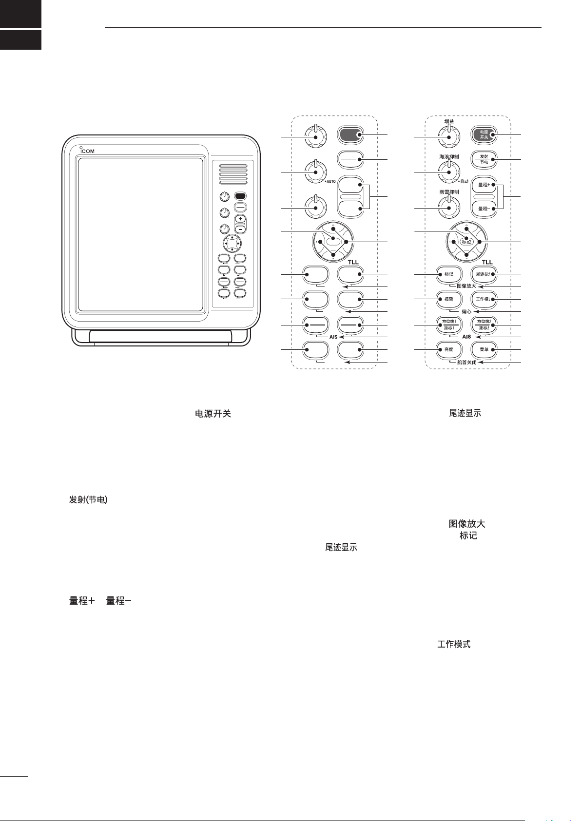
Control panel (English) Control panel (Chinese)
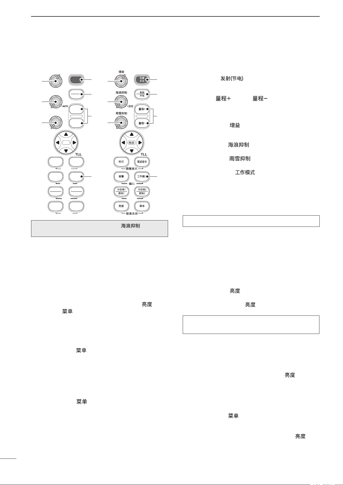
PANEL DESCRIPTION
■ Front panel
q POWER SWITCH [POWER]/[ ] (p. 9)
Push to turn the radar power ON or OFF.
• The standby screen appears for 90 seconds while the
magnetron warms up.
• The initial screen appears and a beep sounds after the
power has been turned ON.
w TRANSMIT/SAVE SWITCH [TX (SAVE)]/
[ ]
➥ Push to toggle between the TX mode and the
standby mode. (p. 9)
➥ Hold down for 1 second to turn ON the power
save function. The radar for TX interval scan is
fixed at 10 revolutions. (p. 12)
• Select the save time in the INT. SETTING menu.
e RANGE UP/ DOWN SWITCHES [+]/[–]/
[ ]/[ ] (p. 9)
Push [+] to increase the screen range.
Push [–] to decrease the screen range.
r UP, DOWN, LEFT, RIGHT KEYS [p] [q] [t] [u]
Set the EBLs, VRMs, alarm area, ATA target, AIS
target and so on.
In the Menu screen, push [p] or [q] to select the
menu items, and then push [t] or [u] to select the
option or set the value.
In the normal operating mode, push a combination
of the [p]/[t] or [p]/[u], or [q]/[t] or [q]/[u] to
move the cross line cursor to the upper left or right,
or lower left or right.
t TRAILS SWITCH [TRAILS]/[
➥ Push to toggle the trail function ON or OFF. This
is useful for watching other ship’s tracks, and approximate relative speed.
• Trail Time can be set in the VIDEO menu.
➥ Hold down for 1 second to output the position
information where the cursor is placed, to the
NMEA output terminals.
• TLL output requires bearing data and position data.
y ZOOM FUNCTION [ZOOM]/[ ] (p. 11)
Simultaneously push [TARGET]/[ ] and [TRAILS]/
[ ] to toggle the ZOOM function ON or OFF.
The ZOOM function enlarges the target to two times
normal size.
• Move the cursor to the target, then turn ON the function.
• The screen zooms the middle of the screen around your
• This function is not usable in the
u MODE SWITCH [MODE]/[ ]
Push to select the Head-up (H UP), Course-up (C
UP), North-up (N UP) or True motion (TM) screens.
• The North-up and Course-up screens can be selected
own ship.
higher ranges.
only when a bearing data input is connected. (pp. 28,
43)
• The TM screen requires bearing data and LOG or posi-
• TheTM screen is not selectable in the 32 NM or higher
tion data. (pp. 28, 43)
range.
] (p. 12)
1
⁄8 and the 32 NM or
1
Page 7
PANEL DESCRIPTION
1
i OFF CENTER FUNCTION [OFF CENT]/[
]
(p. 10)
Simultaneously push [ALM]/[ ] and [MODE]/
[ ] to turn the OFF CENTER function ON or
OFF.
• This function is usable in the 24 NM or less ranges.
o EBL2 (VRM2) SWITCH [EBL2 (VRM2)]/
[ ] (pp. 15, 16)
Push to display the electronic bearing line 2 (EBL2)
and the variable range marker 2 (VRM2), and activate the [t] or [u] for the electronic bearing line
selector and [p] or [q] for the range marker selector.
• When VRM1 and EBL1 ($9 %2) are displayed, the center
of VRM2 appears at the intersection point of VRM1 and
EBL1.
!0 AIS OPERATING MODE SELECTION [AIS]
(p. 24)
➥
Simultaneously push [EBL1(VRM1)]/[ ]
and [EBL2(VRM2)]/[ ] to toggle between
the AIS operating mode and the normal operating
mode.
➥ Hold down [EBL1(VRM1)]/[ ] and
[EBL2(VRM2)]/[ ] for 1 second to
toggle between the AIS display ON and OFF.
!1 MENU SWITCH [MENU]/[
] (pp. 5–7)
Push [MENU]/[ ] to select the VIDEO, FUNC-
TION, ATA AIS, TARGET, INT. SETTING or SERVICE MAN menus. Push [p] or [q] to select the
items and push [t] or [u] to change the setting.
!2 HEADING LINE OFF FUNCTION [HL OFF]/
[
] (p. 9)
While holding down [BRILL]/[ ] and [MENU]/
[ ], the heading line is temporarily turned OFF.
!3 GAIN CONTROL [GAIN]/[
] (p. 9)
Adjusts the receiver amplifier gain.
• Clockwise rotation increases the gain.
• Increased gain may increase screen noise.
!4
SEA CLUTTER CONTROL [SEA]/[ ] (p. 10)
This function serves to eliminate echoes from
waves in close range.
Reduces the receiver gain for close objects within a
radius of approximately 8 nautical miles to eliminate
sea clutter.
Rotate the control fully clockwise to activate the
automatic SEA control function. The SEA indicator
( )
appears in the upper left of the screen.
• Under normal conditions set the SEA to minimum.
• Use this control with caution when the sea is rough.
!5
RAIN CLUTTER CONTROL [RAIN]/[ ] (p. 10)
This function eliminates echoes from rain, snow,
fog, and so on.
Rotate the control fully counter clockwise to deacti-
vate the RAIN function.
The RAIN indicator (
) disappears.
!6 MAN OVERBOARD [MOB]/[
]
Push to mark the man overboard point on the
screen. When a crew member falls overboard, hold
down [MOB]/[ ] for 1 second to display the MOB
symbol ( ) on the screen.
• The MOB readout shows the bearing, distance and estimated time to the MOB point at the current speed.
• Hold down [MOB]/[
function.
• Position and bearing data are necessary.
] for 1 second to cancel the
!7 TARGET SWITCH [TARGET]/[ ] (pp. 19, 23)
❍ Operating in the AIS mode
➥Push to select a target.
➥Hold down for 1 second to toggle the selected
target between activated or sleeping.
❍ Operating in any other mode
➥Push to select the desired ATA target data (1
to 10, or OFF).
➥Hold down for 1 second to set the target as
caught or released.
!8 ALARM SWITCH [ALM]/[
] (p. 17)
➥Push [ALM]/[ ] to toggle the alarm function
ON or OFF.
➥Hold down [ALM]/[ ] for 1 second to enter the
alarm area setting mode.
• Push [p], [q], [t] or [u] to move the cross cursor to
the zone starting point, then hold down [ALM]/[
for 1 second. The starting ring of the zone is created.
Then push [p], [q], [t] or [u] to fix the finish point,
and then push [ALM]/[
will automatically form.
]. The desired alarm zone
!9 EBL1 (VRM1) SWITCH [EBL1 (VRM1)]/
[ ] (pp. 15, 16)
Push to display the electronic bearing line 1 (EBL1)
and the variable range marker 1 (VRM1) and activate [t] or [u] for the electronic bearing line selector, and [p] or [q] for the range marker selector.
• EBL1 bearing and VRM1 distance are displayed in the
bottom window.
• When EBL1 and VRM1 are displayed, the beginning
of EBL2 appears at the intersection point of EBL1 and
VRM1.
@0 DISPLAY BRILLIANCE SWITCH [BRILL]/[ ]
(p. 9)
➥ Push to increase or decrease the brilliance of the
picture on the display.
➥ Hold down for 1 second to select maximum bril-
liance.
➥ The display color changes between green and
red if you continue to hold down this key after the
display is set to maximum brilliance.
The brightness of the symbols, characters and il-
luminations can be independently adjusted in the
“SYMBOL”, “CHARACTER” and “KEY ILLUM” of the
INT. SETTING menu.
]
2
Page 8
1
AIS
:
:
:
:
(0.25)
MTUNE
TVECT
6M
0649NM
NM
CURS
STW
15 7
KT
H UP
0174
˚
R
TRAILS
253 0
˚T
HDG
IR
EBL1
EBL2
WPT
VRM1
VRM2
CURS
1076
˚
0219
˚
2834
˚
0422
NM
001
000
001
0242
NM
0632
NM
34
˚
39720N
135
˚
34420E
ZOOM
ALM
COMPASS
GPS
AIS
ES
005
3/4
#9
@1
@2
@3
@4
@5
@6
@7
@8
@9
#0
#1
#2
#3
#5
#4
#6
#7
#8
$0
$1
$2
$3
$4
$5
$6
$7
$8
$9
%0
%1
%2
%3
%4
%5
%6
%7
%8
%9
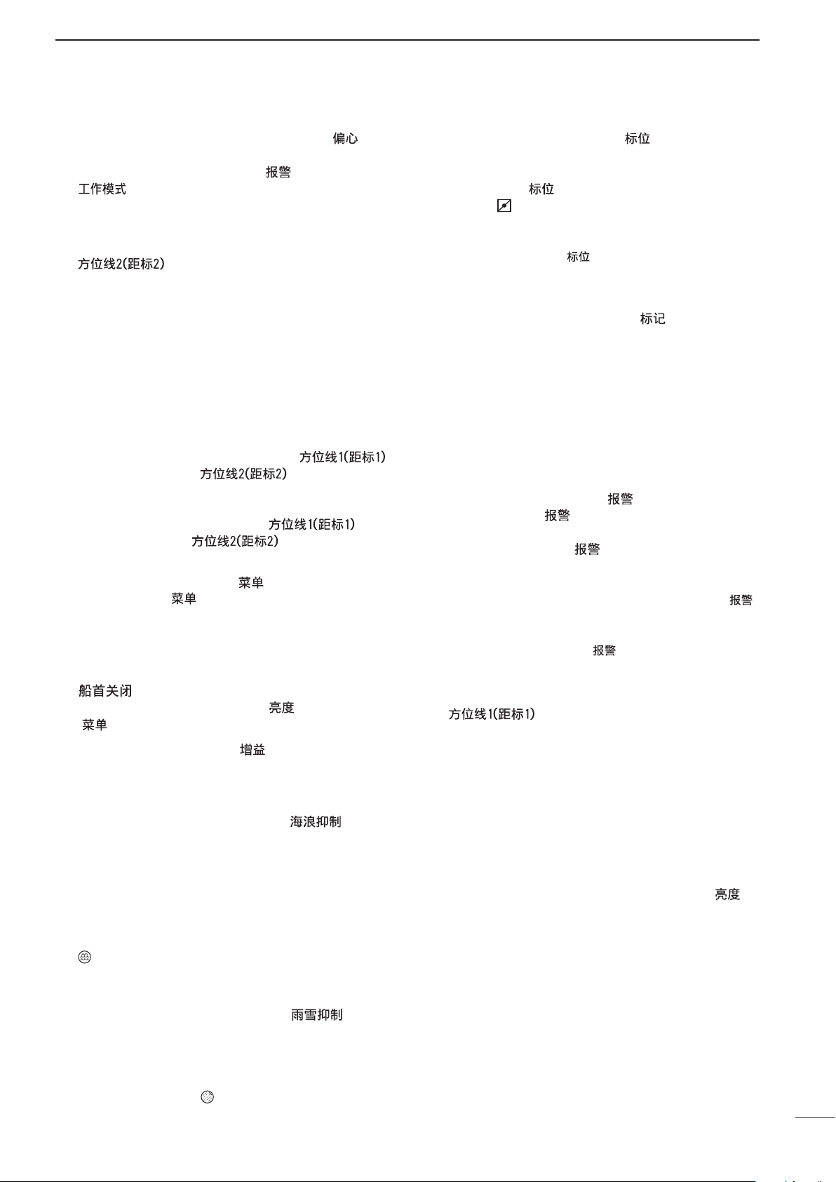
PANEL DESCRIPTION
■ Screen
@1 TUNING MODE INDICATOR (p. 9)
“M.TUNE” appears when the manual tuning func-
tion is in use.
@2 FIXED RING RANGE READOUT (p. 14)
Shows the interval range of the fixed ring.
• This readout appears when “RING” in the FUNCTION
menu is turned ON.
@3 SCREEN RANGE READOUT (p. 14)
Shows the maximum range of the displayed screen.
• The range indicated is nautical miles (NM).
@4 SHIP SPEED READOUT (p. 13)
Shows the ship speed.
• SOG: When GPS is selected in the INT. SETTING
• STW: When LOG is selected in the INT. SETTING
@5 AUTO SEA INDICATOR (p. 10)
Appears when the automatic SEA control function
is turned ON.
@6 LONG PULSE INDICATOR (p. 13)
menu.
menu.
Appears when the long pulse is in use.
@9 HEADING LINE (p. 9)
The heading line indicates the ships bow direction.
#0 ALARM ZONE (p. 17)
Shows the alarm zone.
• Appears when the alarm function is in use.
#1 WAYPOINT MARKER (p. 13)
Shows the waypoint received from navigation equip-
ment.
• This marker appears when “WPT” in the FUNCTION
menu is turned ON.
• To display the waypoint marker, bearing data and
NMEA data in 0183 format is necessary. (p. 43)
#2 FIXED RANGE RINGS (p. 14)
Shows the distance at fixed intervals. The interval
distance is indicated by the ring range readout (@3).
• These rings appear when “RING” in the FUNCTION
menu is turned ON.
#3 AIS INDICATOR (p. 14)
Appears when a valid VDM sentence is input from
the NMEA (AIS) port. If more than the specified AIS
signals that is set in the “NUMBER OF AIS” setting
of the ATA AIS menu are received, this indicator
@7 RAIN CONTROL INDICATOR (p. 10)
Appears when the RAIN function is in use.
@8 MODE INDICATOR
Head-up, Course-up, North-up and True Motion
screens are available.
• N UP and C UP screens require external bearing data.
• TM screen requires bearing data and LOG or position
data.
3
changes to a reverse display (
The indicator disappears if the AIS signal is inter-
rupted for 6 minutes.
#4 GPS INDICATOR (p. 28)
Indicator appears when the NMEA (GPS) is con-
nected.
).
Page 9

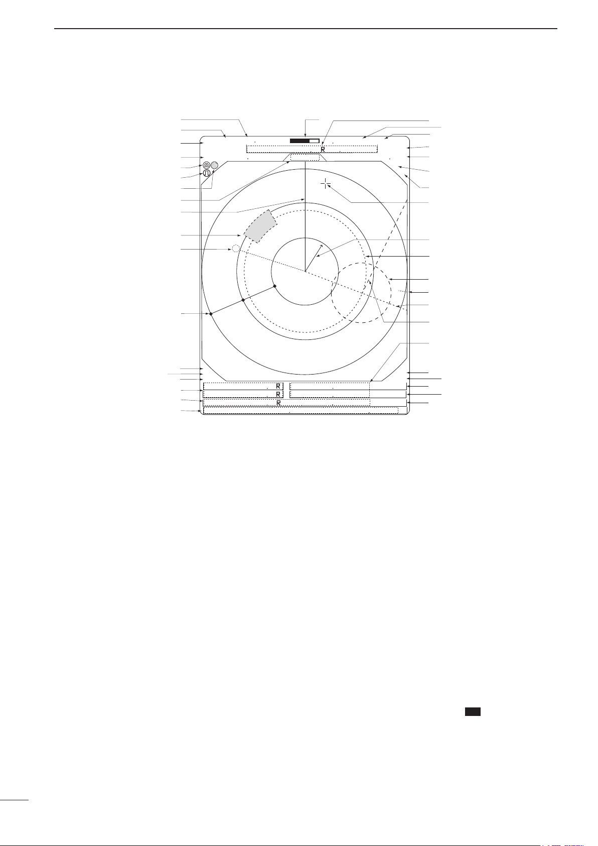
PANEL DESCRIPTION
1
#5 COMPASS/GYRO INDICATOR (pp. 28, 43)
• GYRO: NMEA (gyro) is connected.
• COMPASS: NMEA (compass), N+1 or AUX data is
connected.
#6 EBL1/ 2 READOUTS (pp. 15, 16)
Shows the bearing of the displayed Electronic Bear-
ing Lines (EBL1 and EBL2) when EBL is in use.
#7 WAYPOINT/MOB READOUTS (p. 13)
➥ Shows the bearing and distance to the waypoint
received from navigation equipment.
• This readout appears when “WPT” in the FUNCTION
menu is turned ON.
• To display the waypoint/MOB marker, bearing data
and NMEA data in 0183 format is necessary. (p. 43)
➥ Shows the bearing and distance to the MOB
(Man Over Board) event marker.
• Push [MOB]/[ ] to cancel the readout and the
symbol.
#8 POSITION/CURSOR READOUT (p. 13)
Shows your own ship or cursor latitude and longi-
tude readout when external NMEA data in 0183 format is connected.
• Select ‘SHIP’ or ‘CURS’ in the “POSN DISP” item of the
FUNCTION menu.
• To display the POSITION, NMEA 0183 is necessary.
• To display the CURSOR, NMEA 0183 and bearing data
are necessary.
#9 TUNING LEVEL INDICATOR (p. 9)
Shows the receiver tuning level.
$0 CURSOR INDICATOR
Shows the bearing and distance to the cursor.
• R: Relative bearing, T: True Bearing, M: Magnetic bearing
$1 VECTOR INDICATOR (p. 19)
Shows the ATA, AIS and OWN vector type.
• T: True vector, R: Relative vector
$2 VECTOR TIME INDICATOR (p. 19)
Shows the vector time. Select vector time in “VECT
TIME” of the TARGET menu.
$3 TRAILS INDICATOR (p. 12)
Shows the trail time.
• The echo remains, with gradation, during the trail time
period on the screen. (Except for the trail time;
• Progressing time counter starts counting until the timer
reaches the trail time.
∞)
$4 HEADING INDICATOR
Shows the heading bearing readout.
• HDG: When “BRG INPUT” in the INT. SETTING menu is
selected “NMEA,” “N+1” or “AUX.”
• COG: When “BRG INPUT” in the INT. SETTING menu is
selected “GPS.”
• The HDG readout indicates the bow of the ship’s bear-
ing in a clockwise direction from north.
• R: Relative bearing, T: True Bearing, M: Magnetic bearing
$5 IR INDICATOR (p. 11)
Eliminates or reduces interference caused by other
radar operating nearby.
• This indicator appears when “IR” in the VIDEO menu is
set to 1 or 2.
$6 ECHO STRETCH INDICATOR (p. 11)
Appears when the echo stretch function is in use.
• This indicator appears when “STRETCH” in the VIDEO
menu is turned ON.
$7 CROSS LINE CURSOR
Used to measure the bearing and distance, setting
the alarm zone, selecting the ATA/AIS targets, and
so on.
• Push [p], [q], [t] or [u] one or more times to move
the cursor.
$8 OWN SHIP VECTOR INDICATOR
Shows the vector of your own ship.
$9 VRM 1 (pp. 15, 16)
%0 VRM 2 (pp. 15, 16)
Used to measure distance. When a target is se-
lected, the VRM1/2 readout (%4) shows its distance.
%1 NORTH MARK
The north mark shows the true north direction.
%2 EBL1 (pp. 15, 16)
%3 EBL2 (pp. 15, 16)
Used to measure bearing. When a target is se-
lected, the EBL readout (#6) shows its bearing.
%4 VRM1/2 READOUTS (pp. 15, 16)
Shows the distance of the displayed Variable Range
Markers (VRM1 and VRM2) when the VRM is in
use.
• Nautical miles (NM) or kilometers (KM) can be selected
in the FUNCTION menu as the distance unit.
%5 ALARM INDICATOR (p. 17)
Appears when the alarm function is in use.
%6 ZOOM INDICATOR (p. 11)
Appears when the zoom function is in use.
• Push [TARGET]/[ ] and [TRAILS]/[ ] simul-
taneously to turn the function ON or OFF.
%7 TIME INDICATOR
%8 TIME INDICATOR
Shows the estimated time to the marker edge from
the center of the marker, at the current speed.
%9 TIME INDICATOR
Shows the estimated time to the waypoint at the
current speed.
4
Page 10

2
VIDEO MENU
D.RANGE
IR
STRETCH
PULSE
SEA
TRAIL TIME
ON
1 2
MANUAL
AUTO
MID. WIDE
OFF
OFF
SP
6S
3M
15S6M30S
15M
1M
TUNE
1 2 34
NAR.
LP
FUNCTION MENU
POSN DISP
WPT ON
DIST UNIT
BRG
DIRECTION
ZONE ALARM
BEEP
MAG
PT/SB
KM
OUT
ON
OFF
CURS
NM
TRUE
TRUE
IN
RING
OFF
ON
OWN VECT
ON
OFF
SHIP
360
˚
R
OFF
The SERVICE MAN MENU is described in ‘Section 10 SERVICE MAN MENU.’ Please see Section 10 for details.
MENU
■ VIDEO MENU
DTUNE
• AUTO: Automatic tuning.
• “A.TUNE” appears for approximately 2 sec-
onds, instead of the screen display, when
first transmitting after turning ON the power.
The unit also retunes in some cases.
• MANUAL: Manual tuning.
q Push [u] to select [MANUAL], then
push [q] to activate the manual tuning
slider.
w Push [t] or [u] to adjust the desired
tuning level.
DD.RANGE
Select the dynamic range of the PPI (Plan Position Indicator).
• NAR.: Narrow dynamic range. Even weak reections are displayed as strong reections.
• MID.: Mid dynamic range.
• WIDE: Wide dynamic range. You can easily dis-
tinguish between weak reflections and
strong reections.
DIR
• OFF: Turn OFF the Interference Reduction
function.
•
1 or 2 (ON):
“IR” appears on the screen.
DSTRETCH
• OFF: Turn OFF the echo stretch function.
• ON: Turn ON the echo stretch function.
DPULSE
• SP: Select the pulse width to short.
• LP: Select the pulse width to long.
DSEA
• The SEA knob can be used to ne tune the sea clut-
ter of the display after one of our main levels are selected based on the height of the antenna and sea
5
conditions.
DTRAIL TIME
• 6S, 15S, 30S, 1M, 3M, 6M, 15M or
Select the trail time.
Turn ON the Interference Reduction func-
tion 1 (Low) or 2 (High).
“ES” appears on the screen.
“
” appears on the screen.
∞:
■ FUNCTION MENU
DRING
• OFF: Turn OFF the xed range ring display.
• ON: Turn ON the xed range ring display.
DWPT
• OFF: Do not display the waypoint on the screen.
• ON: Display the waypoint on the screen.
Waypoint, bearing and position data are re-
quired.
DPOSN DISP
• SHIP: Display your own ship’s position.*
• CURS: Display the cursor position.*
1
*
External latitude/longitude data required.
2
*
External latitude/longitude data and bearing data re-
quired.
DDIST UNIT
• NM: Display the distance unit in Nautical Miles.
• KM: Display the distance unit in Kilometers.
DBRG
Select the displayed bearing type, no relation with the
bearing data format (NMEA, N+1, AUX or GPS).
• TRUE: Select the true North bearing.
• MAG: Select the magnetic North bearing.
DDIRECTION (except HDG and CSE) (p. 15)
• TRUE: True or magnetic direction.
• 360°R: Relative direction
• PT/SB: Bow direction
DZONE ALARM
• IN: An alarm sounds when the target comes
into the zone.
• OUT: An alarm sounds when the target goes out
of the zone.
DBEEP
• OFF: Turn OFF* the beep tone.
• ON: Turn ON the beep tone.
* Except for the alarm function.
DOWN VECT
• OFF: Do not display your own ship’s vector.
• ON: Display your own ship’s vector.
Bearing data, position data and ship speed
are required.
1
2
Page 11

■ ATA AIS MENU
ATA AIS MENU
ATA No.DISP OFF ALL
ON
OFF
ATA ALARM ONOFF
AIS DISPLAY ONOFF
AIS ALARM ONOFF
AIS RANGE 8.0NM
AUTO ACTIVATE
1.0NM
NUMBER OF AIS
100
SLOW WARN
0.1KT
LOST AIS TRGT
ERASE
SEL
ATA
DATA (Automatic Tracking Aid)
• OFF: Turn OFF the ATA function.
• ON: Turn ON the ATA function.
DATA No. DISP
Select the target identification number type that appears at the right side of the mark.
• OFF: Do not display any mark number.
• SEL: Display only the selected mark num-
ber.
• ALL: Display all mark numbers.
DATA ALARM*
• OFF: Turn OFF the ATA alarm function.
• ON: Turn ON the ATA alarm function.
DAIS DISPLAY
• OFF: Turn OFF the AIS display.
• ON: Turn ON the AIS display.
DAIS ALARM*
• OFF: Turn OFF the AIS alarm function.
• ON: Turn ON the AIS alarm function.
* An ATA alarm or AIS alarm sounds when the CPA and TCPA
reach the limit.
DAIS RANGE
Set the AIS display range to between 0.1 and 36.0 NM
or ∞.
• 0.1 to 36.0NM: Select the range from your vessel.
• ∞: The received AIS information are dis-
played up to the
setting.
DAUTO ACTIVATE
Set the distance to automatically turn the sleeping AIS
target into an activated target.
• OFF: Turn OFF the Auto Activate function.
• 0.1 to 9.9NM: Select the distance from your vessel.
DNUMBER OF AIS
Select the maximum number of AIS targets that can
be displayed on the screen to between 10 and 100 in
10 digit steps.
“NUMBER OF AIS”
DSLOW WARN
The AIS unit calculated COG (Course Over Ground)
data of a vessel that is at anchor or drifting is unreliable, and therefore the CPA (Closest Point of Approach) and TCPA (Time to CPA) data may not be
correctly calculated. If a vessel is anchored in your
alarm zone, the unreliable data can cause the collision
alarm to sound many times, even if there is no real
danger. To prevent this, when the anchored vessel’s
SOG (Speed Over Ground) is less than this set value,
the Slow Warn function assumes that vessel’s COG is
fixed towards your vessel and an alarm will sound.
• OFF: Turn OFF the Slow Warn function.
• 0.1 to 4.9KT: Select the vessel’s speed.
DLOST AIS TRGT
Erase all of the Lost targets.
Push [u] to display the confirmation “SURE?,” then
push [u] again to clear all of the Lost targets on the
screen.
About “Lost Target”: A vessel is regarded as a “Lost
target” after a specified period of time has passed
since the vessel last transmitted data, as described
below.
The “Lost target” icon disappears from the screen 6
minutes and 40 seconds after the vessel was regarded
as a “Lost target.”
The criteria to become a Lost target:
Except
Vessel type
Except
Class B
1
Class B
Vessel is at anchor, moored and moving
2
more than 3 knots
Except
Class B
3
Class B
Vessel is moving between 0 and 14 knots
4
while changing course
Vessel is moving between 14 and 23
5
knots
Vessel is moving between 14 and 23
6
knots while changing course
7
Vessel is moving more than 23 knots
Vessel is moving more than 23 knots
8
while changing course
Vessel is at anchor, moored
and moving less than 3 knots
Vessel is moving less than 2
knots
Vessel is moving between 0
and 14 knots
Vessel is moving between 2
and 14 knots
Class
18 min. —
— 18 min.
1 min. N/A
1 min. —
— 3 min.
1 min. N/A
36 sec. 90 sec.
36 sec. N/A
12 sec. 30 sec.
12 sec. N/A
MENU
B
2
Class
B
6
Page 12

2
TARGET MENU
VECT MODE
VECT TIME
CPA LIMIT
TCPA LIMIT
TRUE REL
6M
1.0NM
1 M
TARGET TRACK
1 M
INT. SETTING
BRG INPUT
SPD INPUT
TX INH START
TX INH ANGLE
SAVE TIME
SYMBOL
CHARACTER BRILL
NMEA
30M
LOG
6M 15M
MANUAL
AUTO
N+1 AUX GPS
GPS
0
˚
0
˚
KEY ILLUM
MAG VAR
1 2 3
1 2 3
123 4
0.0
˚
W
1M
MENU
■ TARGET MENU
DVECT MODE
• TRUE: Select the true vector mode.
• REL: Select the relative vector mode.
DVECT TIME
Set the vector length (time) to 15 seconds, 30 seconds
or 1 to 15 minutes.
DCPA* LIMIT
• 0.1 to 10.0NM: Set the CPA (Closest Point of Ap-
proach) limit by pushing [t] or [u].
DTCPA* LIMIT
• 1 to 60M: Set the TCPA (Time to CPA) limit time
by pushing [t] or [u].
* CPA/TCPA: Closest Point of Approach and Time to Closest
Point of Approach limits are set to give a warning when a
target or targets enter those limits around your own ship.
■ INT. SETTING MENU
DMAG VAR
• AUTO: Automatically revise magnetic variations.
NOTE: NMEA data is required. NEVER select
“AUTO” without NMEA data; incorrect variation data may entered. (p. 43)
• MANUAL: Manually revise magnetic variation.
q Push [u] to select [MANUAL], then
push [q].
w Push [t] or [u ] to set the revised
value.
DBRG INPUT
• NMEA: NMEA0183 bearing data format.
• N+1: N+1 data format.
• AUX: Other format.
• GPS: Reads NMEA0183 COG format data as
HDG format. (The course may not match
with other HDG format and includes
error.)
DTARGET TRACK
The track data is updated at this specified tracking interval. Select the track interval time between OFF, 15
seconds, 30 seconds and 1 to 15 minutes.
After 5 dots are displayed, the oldest dot disappears at
the time when the next dot appears.
7
DSPD INPUT
• GPS: Use the GPS NMEA speed data.
• LOG: Use the speed sensor data.
When “BRG INPUT” in the INT. SETTING menu is selected
“GPS,” selectable option is only “GPS.”
DTX INH START
• 0 to 359°: Push [t] or [u] to enter the start point of
the TX inhibit area.
DTX INH ANGLE
• 0 to 90°: Push [t] or [u] to enter the TX inhibit
area.
DSAVE TIME
• 1M, 6M, 15M or 30M:
Select the standby time during the save
mode.
• The radar for TX interval scan is xed at 10
revolutions.
DSYMBOL
• 1/2/3: Select the symbol brightness.
(Includes AIS icons.)
DCHARACTER
• 1/2/3: Select the character brightness.
DKEY ILLUM
• 1/2/3/4: Select the key illumination brightness.
Page 13
■ Checking the installation
1
(0.25)
T.VECT 6M
0.000NM
NM
CURS
SOG17.7KT
H UP
000.0˚T
HDG253.4˚T
EBL1
EBL2
MOB
VRM1
VRM2
CURS 34˚ 37.72N
135˚ 34.42E
STBY
IR
COMPASS
GPS
1
(0.25)
T.VECT 6M
0.000NM
NM
CURS
SOG17.7KT
H UP
000.0˚T
HDG253.4˚T
EBL1
EBL2
MOB
VRM1
VRM2
CURS 34˚ 37.72N
135˚ 34.42E
IR
COMPASS
GPS
0.45
REV *.*
ROM OK
RAM OK
BASIC OPERATION
3
Before turning ON the power, be sure all the connections are complete. The checklist at right may be helpful for necessary confirmation.
CAUTION: Connect the scanner unit before turning ON
the power. Otherwise the magnetron inside the scanner
unit might be damaged.
■ Turning power ON/OFF
DChecklist
q The four bolts securing the scanner unit must be
firmly tightened.
w Cabling must be securely attached to a mast or
mounting material, and must not interfere with the
rigging.
e Be sure waterproofing procedures are completed
on the system cable.
r The power connections to the battery must be of
the correct polarity.
t Be sure that the plugs at the rear of the display unit
have been connected correctly and securely.
(See page 28 for details.)
q Push [POWER]/[ ] to turn ON the power.
• The initial screen appears and the magnetron warm up
time is counted down on the screen.
•
The magnetron inside the scanner unit warms up for 90
seconds.
• [POWER]/[ ] is disabled for 2 seconds after
the power is turned OFF.
w When the countdown is completed, the Standby
screen appears.
e Push [TX]/[ ] to start scanning and select
the Plan Position Indicator (PPI) screen.
• Targets and heading markers appear.
• The screen appears approximately 2 seconds after
turning ON the power, when ‘AUTO’ is selected in the
“TUNE” item of the VIDEO menu.
r Push [POWER]/[ ] to turn OFF the power.
8
Page 14
3
TX
SAVE
TARGET TRAILS
MODEALM
+
-
MOB
MENU
EBL2
VRM2
EBL1
VRM1
BRILL
ZOOM
OFF CENT
HL OFF
AIS
AIS
GAIN
SEA
RAIN
POWER
e
q
w
u
r
t
y
e
q
w
u
r
t
y
BASIC OPERATION
■ Basic operation
q Turn ON the power.
w Push [TX]/[ ] after the countdown disap-
pears from the screen.
• See “Turning power ON/OFF” on page 8.
e Push [+]/[ ] or [–]/[ ] one or more times
to select the display range.
• The screen range readout shows the maximum range
of the screen.
r Rotate [GAIN]/[ ] to the 1 o’clock position.
• Clockwise rotation increases the gain.
• Increased gain may increase screen noise.
t Rotate [SEA]/[ ] to set the sensitivity time
control to minimum.
y Rotate [RAIN]/[ ] to set the rain clutter con-
trol to minimum.
u Push [MODE]/[ ] to sel ect ei ther t he
Head-up; H UP, Course-up; C UP, North-up; N UP
or True Motion; TM screen.
C UP, N UP or TM can be selected only when
bearing, position or speed data is provided.
(See page 43 for details)
9
CAUTION: When setting the [SEA]/[ ] control to
a fully clockwise position, close targets are blanked.
DHeading marker
The heading marker is a line that shows your ship’s
bow direction. (This marker will appear in the center of the screen when the Head-up screen H UP
is selected.) The heading marker can be hidden
when the desired target is located under the heading
marker.
➥ Simultaneously hold down [BRILL]/[
[MENU]/[ ] to hide the heading marker.
DFixed range rings
The fixed range rings can be used for rough distance
measurements. (p. 14)
➥ Push [MENU]/[
then push [q] to select RING. Push [u] to turn ON
the ring.
DManual tuning
The receiver tuning can be manually adjusted.
➥ Push [MENU]/[
select MANUAL. Push [q] to activate the manual
] to open the FUNCTION menu,
] to open the VIDEO menu, then
tuning slider, then push [t] or [u] to set the tuning
level indicator to the maximum level. (p. 5)
• “M.TUNE” appears at the top of the display.
] and
NOTE:
Manual adjustment can be used. (See below.)
DBrilliance adjustment
The intensity of the screen can be adjusted. When
you require continuous operation, but not constant
viewing, a lower setting can increase the life of the
LCD display.
➥ Push [BRILL]/[
] to increase or decrease the
brilliance of the picture on the display.
➥ Hold down [BRILL]/[ ] for 1 second to select
maximum brilliance.
NOTE: High intensity will shorten the life of the LCD
display.
• Display color
Two display colors can be selected between green
and red.
➥ The display color changes between green and red
if you continue to hold down [BRILL]/[
] after the
display is set to maximum brilliance.
• Key illumination
The backlighting of the keys can be adjusted for convenient operation. (p. 7)
➥ Push [MENU]/[
] one or more times to select the
INT. SETTING menu. Push [t] or [u] to select the
illumination level.
• Key illumination corresponds with [BRILL]/[ ] control.
Page 15
BASIC OPERATION
Adjust RAIN control
Small echos
Adjust SEA control
Echos from sea waves
With OFF CENTER ON
Normal screen
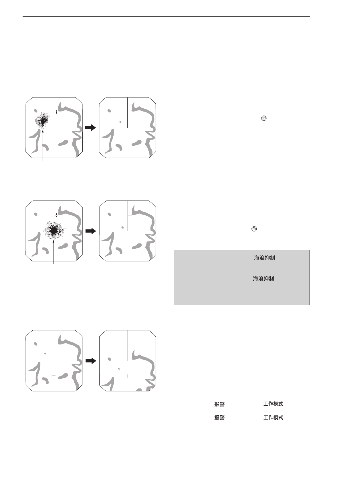
The following are typical basic operation examples, which may hinder radar reception (sea clutter, precipitation
interference and echoes from other radar).
3
■ RAIN function
This function eliminates echoes from rain, snow, fog
etc.
• Rotate the control fully counterclockwise to deactivate the
control function. The RAIN indicator (
• NOTE: DO NOT reduce the echoes too much, otherwise
you may miss weaker targets.
) disappears.
■ SEA function
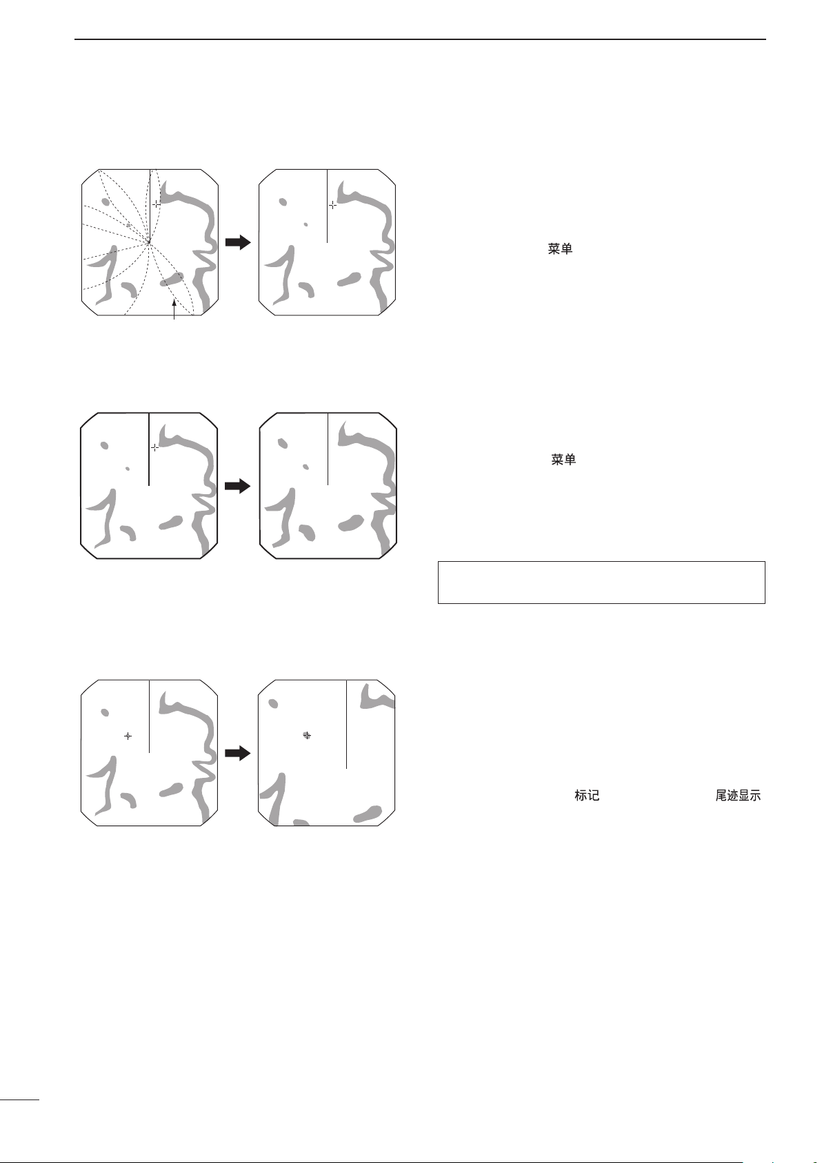
■ OFF CENTER function
This function serves to eliminate echoes from waves at
close range. Reduce the receiver gain for close objects
within a radius of 8 NM to eliminate sea clutter.
• Rotate the control fully clockwise to activate the automatic
control function. SEA indicator (
left corner of the screen.
) appears in the upper
WARNING: The [SEA]/[ ] control re-
duces the receiver sensitivity of objects within 8 NM.
Therefore, caution and careful adjustment are necessary when using the [SEA]/[ ] control.
Small objects may not be displayed on the screen
when strong echoes from rain or islands within 1 NM
while the automatic SEA function is activated.
The scanning area can be shifted in a desired direction
and can be partially enlarged. This is useful when
Head-up* screen is selected, and you want to enlarge
the bow direction display, or the center of the screen
shifts in the direction of the intersection.
• This function is selectable in 24 NM or shorter ranges.
*This function is not selectable in the TM screen.
q Push [p], [q], [t ] or [u] to move the cursor
where you want to shift the center of the screen.
• Maximum offset is up to 75% of the screen.
w Push [ALM]/[ ] and [MODE]/[ ] simulta-
neously to shift the screen.
e Push [ALM]/[ ] and [MODE]/[ ] simulta-
neously again to return to the normal screen.
10
Page 16
3
With IR function ON
Radar interference
With STRETCH ON
Normal screen
With ZOOM function ON
Normal screen
BASIC OPERATION
■ IR function
Radar interference may appear when another ship’s
radar is operating on the same frequency band in
close proximity. The IR function can eliminate this type
of interference. (p. 5)
■ STRETCH function
q Push [MENU]/[
w Push [q] to select “IR.”
e Push [t] or [u] to select IR function 1, 2 or OFF.
• “IR” appears in the upper right of the screen, when the
function is activated.
The blips can be magnified electronically for easier
viewing of small targets. (p. 5)
q Push [MENU]/[
the VIDEO menu.
w Push [q] to select “STRETCH”, then push [u] to
turn ON the function.
• “ES” appears in the upper right of the screen, when the
function is activated.
NOTE: Turn OFF this function during normal opera-
tion.
] to call up VIDEO menu.
] one or more times to select
■ ZOOM function
The ZOOM function expands the target to two times
normal size.
• This function is selectable up to a 24 NM range or shorter
q Push [p], [q], [t] or [u] to move the cursor to the
w
• “ZOOM” appears in the lower right of the screen.
1
except
⁄8 NM.
desired target.
Push [TARGET]/[ ] and [TRAILS]/[ ]
simultaneously to toggle the ZOOM function between
ON and OFF.
11
Page 17
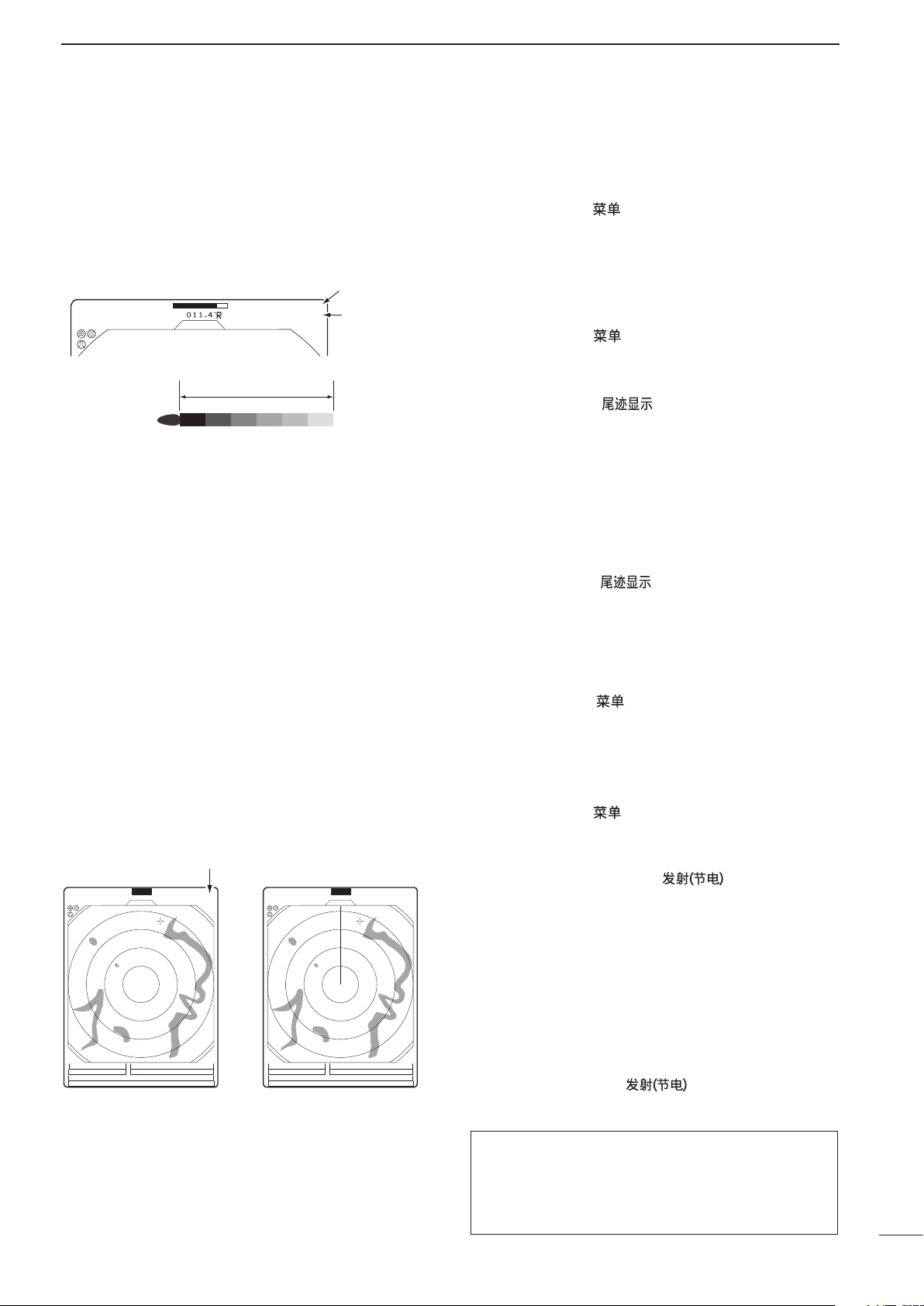
■ TRAILS function
3/4
(0.25)
M.TUNE
1:0 5
NM
CURS
STW 15.7KT
H UP
HDG 253.9˚T
6M
TRAILS
IR
ES
T.VECT
0.453NM
TRAIL
indicator
Trail interval
counter
Trail time
CURS 34˚ 37.72N CURS 34˚ 37.72N
1
(0.25)
T.VECT 6M
0.900NM
NM
CURS
SOG17.7KT
H UP
014.6˚T
HDG273.9˚T
IR
ES
EBL1
EBL2
MOB
VRM1
VRM2
135˚ 34.42E
0:48
SAVE
Hold down [TX] for 1 second
to turn ON the SAVE function.
Scan and STBY alternates
Count down the standby time
1
(0.25)
T.VECT 6M
0.900NM
NM
CURS
SOG17.7KT
H UP
014.6˚T
HDG273.9˚T
IR
ES
EBL1
EBL2
MOB
VRM1
VRM2
135˚ 34.42E
0:00
SAVE
COMPASS
GPS
COMPASS
GPS
BASIC OPERATION
3
The trails function memorizes echoes continuously or
at constant intervals. This is useful for watching other
ships’ tracks, approximately relative speed, etc.
• Setting the trail interval time
q Push [MENU]/[ ] one or more times to select the
VIDEO menu.
• Push [q] one or more times to select “TRAIL TIME.”
w Push [t] or [u] to select trail interval time.
• 6 seconds, 15 seconds, 30 seconds, 1 minute, 3 minutes, 6 minutes, 15 minutes and
∞ (continuous) are se-
lectable.
e Push [MENU]/[ ] one or more times to exit the
menu.
• Using the TRAILS function
q Push [TRAILS]/[
] to turn ON the trail func-
tion.
• “TRAILS” and trail interval time appears in the upper
right of the screen.
• Trail interval counter starts to count up to the trail time.
w All displayed echoes at the plotted time are mem-
orized and displayed with a graduated intensity
together with the current echoes.
• Echoes are displayed with minimum intensity when “∞”
is selected.
e Push [TRAILS]/[ ] to cancel the trail function
and erase the plotted echoes.
• “TRAILS” and trail interval time disappears.
■ Power save function
The power save function conserves the boat’s battery
power by pausing the transmission. The standby
(pausing) times are selectable (rotation number is
fixed to 10).
For example, when 1 minute is selected, the scanner
rotates 10 revolutions; then stops for 1 minute, and
then repeats this sequence while the power save function is activated.
DSetting the scanning standby time
q Push [MENU]/[ ] one or more times to select
the INT. SETTING menu.
w Push [q ] one or more times to select “SAVE
TIME.”
e Push [t] or [u] to select standby time.
• 1, 6, 15, and 30 minutes are selectable.
r Push [MENU]/[ ] one or more times to exit the
menu.
DUsing the power save function
q Hold down [TX (SAVE)]/[
] for 1 second to
turn ON the power save function.
• The save indicator appears in the top of the screen.
w After the scanning rotations are finished, transmis-
sion and rotation are suspended until the selected
standby time elapses.
• The display shows the last scanned echoes until the
scanning restarts.
• “SAVE” and standby time appear in the top of the screen
and the standby time is counted down.
e After the selected standby time elapses, transmis-
sion and rotation restart.
r Push [TX (SAVE)]/[ ] to cancel the power
save function.
• The save indicator turns OFF.
NOTE: When you use the power save function
together with the alarm function, the LCD display is
turned OFF until an object enters the programmed
alarm zo ne, t herefore, more powe r s av ing is
possible. (p. 17)
12
Page 18

3
BASIC OPERATION
■ Ship speed indication
When the ship speed data in NMEA 0183 format is applied, the radar can display the ship speed. Knots (KT)
or kilometers/hour (KM/h) are automatically selected
in the normal screen (p. 3) by selecting nautical miles
(NM) or kilometers (KM) respectively.
q Push [MENU]/[
the FUNCTION menu.
w Push [q] one or more times to select “DIST UNIT.”
e Push [t] or [u] to select the ship speed indication
to NM or KM.
r Push [MENU]/[ ] one or more times to exit the
menu.
] one or more times to select
■ Position indication
When latitude/longitude data in NMEA 0183 format is
applied, the radar can display the latitude and longitude of your ship’s or cursor position in the bottom of
the display. (To display the CURSOR position, bearing
data is necessary.) (p. 43)
q Push [MENU]/[
the FUNCTION menu.
w Push [q ] one or more times to select “POSN
DISP.”
e Push [t] or [u] to select the ship position or cursor
position.
r Push [MENU] one or more times to exit the menu.
] one or more times to select
■ Waypoint indication
When waypoint data received from navigation equipment in NMEA 0183 format is applied, the radar can
display the waypoint. To display the waypoint marker,
bearing data is necessary. (p. 43)
q Push [MENU]/[
the FUNCTION menu.
w Push [q] one or more times to select “WPT.”
e Push [t] or [u] to turn the waypoint icon ON or
OFF.
r Push [MENU]/[
menu.
] one or more times to select
] one or more times to exit the
■ Long pulse function
To magnify the blips for easier viewing of small targets, the long pulse and echo stretch (p. 11) functions
are usable. When the long pulse is used in the 3⁄4 to 3
NM range, this function magnifies target echoes to the
backward direction of the target.
• Pulse selection
q Push [MENU]/[
the VIDEO menu. (p. 5)
w Push [q] one or more times to select “PULSE.”
e Push [t] or [u] to select SP (Short Pulse) or LP
(Long Pulse).
• When “LP” is selected, “ ” appears in the upper left of
the screen.
r Push [MENU]/[ ] one or more times to exit the
menu.
NOTE: To select SP (Short Pulse) increases the target distance resolution. (p. 27)
] one or more times to select
■ Bearing setting
The radar bearing interface accepts NMEA, N+1, AUX
or COG data format and the bearing can use a magnetic or true north type. When a true north type bearing is used, the variation from magnetic north, etc.,
can be adjusted on 0.1˚ steps.
DSetting the bearing type
q Push [MENU]/[
the FUNCTION menu.
w Push [q] one or more times to select “BRG.”
e Push [t] or [u] to select magnetic or true north
type.
• All displayed bearing readouts show the selected bearing type.
DSetting the magnetic variation
q Push [MENU]/[ ] one or more times to select
the INT. SETTING menu.
w Push [q] one or more times to select “MAG VAR.”
e Push [t] or [u] to select an AUTO* or MANUAL
variation.
r When a MANUAL variation is selected, push [q],
then push [t] or [u] to set the bearing variation.
t Push [MENU]/[ ] one or more times to exit the
menu.
] one or more times to select
13
* NOTE: NMEA data is required for auto variation. NEVER
select “AUTO” variation without NMEA data, incorrect variation data may entered.
Page 19

DISTANCE AND DIRECTION MEASUREMENTS
1
(0.25)
T.VECT
0.900NM
NM
CURS
SOG 0.0KT
H UP
014.6˚T
HDG
IR
ES
EBL1
EBL2
W
PT
VRM1
VRM2
CURS 34˚ 37.72N
135˚ 34.42E
Fixed ring
Ring range readout
Range (nm)
Ring (nm)
1 1.5 234681216243236 48*
1
⁄
8
1
⁄
4
1
⁄
2
3
⁄
4
25534646464646466
112244886
64
†72†
46
1216
1
⁄
20
1
⁄
20
1
⁄
10
1
⁄
4
1
⁄
4
1
⁄
4
1
⁄
2
1
⁄
2
NOTE: When the screen is shifted, the number of rings may differ.
*Available for the MR-1200TII/TIII.
†
Available for the MR-1200TIII only.
■ Distance measurement
4
TYPE
Displays fixed rings.
RING
Suitable for rough estimations from your
own ship to any target.
Displays a variable range marker and
activated by [p ] or [q] for the range
VRM1
marker selector.
Suitable for accurate measurem ents
from your own ship to a target.
Normally functions the same as VRM1.
When the VRM1 and EBL1 selects a
target, the center of VRM2 appears at
VRM2
the intersection point.
Suitable for accurate measurem ents
from target to target.
DUsing the fixed rings
DESCRIPTION
Two measurement procedures can be used with this
radar. Use them separately or jointly is possible.
The distance unit, nautical miles (NM) or kilometers
(KM) is selected in the FUNCTION menu (p. 5).
q Push [MENU]/[ ] one or more times to select the
FUNCTION menu.
w Push [q] one or more times to select “RING.”
e Push [u] to turn ON the RING function and display
the fixed rings.
• The interval range appears on the right of the screen
range readout.
• The ring range is xed depending on the screen range.
(See below.)
r Push [MENU]/[ ] one or more times to exit the
menu.
t To clear the fixed rings, push [t] to turn OFF the
function, as described in step e above.
DUsing the variable range marker
q
Push [EBL1 (VRM1)]/[ ] to display VRM1
and EBL1; then push [p] or [q] to set the marker.
• The range between the ship and the target is indicated
in the VRM readouts.
w
Push [EBL2 (VRM2)]/[ ] to display VRM2
and EBL2; then push [p] or [q] to set the marker.
• The range between the ship and the target is indicated
in VRM readouts.
• When VRM1 and EBL1 are displayed, the center of
VRM2 appears at the intersection point of VRM1 and
EBL1.
• The VRM2 disappears when [EBL1 (VRM1)] is pushed.
e Push [EBL1 (VRM1)]/[ ] to exit the
menu display.
14
Page 20

EBL1
VRM1
EBL2
EBL1
readout
EBL2
readout
VRM2
VRM1 readout
VRM2 readout
4
DISTANCE AND DIRECTION MEASUREMENTS
■ Bearing and Distance measurement
This radar has two Electronic Bearing Lines (EBL) to
indicate the target direction from your ship or a target.
DUsing the EBL and VRM
q Push [p], [q], [t] or [u] to move the cursor onto
the desired target.
w Push [EBL1 (VRM1)]/[ ] to display the
EBL1 and VRM1.
• Push [t] or [u] to rotate the electronic bearing line.
• Push [u ] to rotate clockwise and push [t] to rotate
• Push [p] or [q] to increase or decrease the variable
• The EBL1 and VRM1 readouts indicate the target bear-
• The EBL readouts indicate the target bearing;
0 to 360°R: Relative direction, when ‘360°R’ is se-
P/S 0 to 180°: Bow direction, when ‘PT/SB’ is selected
0 to 360°T*: True or magnetic bearing, when select-
e Push [EBL1 (VRM1)]/[ ] to clear EBL1
and VRM1.
• Cursor remains on the display.
r Push [p], [q], [t] or [u] to move the cursor onto
the desired target.
t Push [EBL2 (VRM2)]/
EBL2 and VRM2 on the display.
• When EBL1 and VRM1 are displayed, the beginning
• EBL2 and VRM2 disappear when [EBL1 (VRM1)]/
y To clear EBL1 and VRM1, push [EBL1 (VRM1)]/
[ ].
counterclockwise.
range marker ring size.
ing and distance.
lected in the DIRECTION item of the
FUNCTION menu. (See page 5)
in the DIRECTION item of the FUNCTION menu. (See page 5)
ing ‘TRUE’ in the DIRECTION item of the
FUNCTION menu. (See page 5)
*Bearing data is required. (p. 43)
[ ]
of EBL2 and VRM2 appears at the intersection point of
EBL1 and VRM1.
[
] is pushed.
to display
15
Page 21

DISTANCE AND DIRECTION MEASUREMENTS
3/4
MTUNE
TVECT
3M
1141NMNM
CURS\
SOG
km/h
H UP
3171
˚M
HDG
IR
ES
EBL1
EBL2
WPT
VRM1
VRM2
3211
˚M
0890
˚T
0852NM
0814NM
POSN
ALM
GYRO
GPS
EBL2
EBL1
VRM2
VRM1
3/4
TVECT
6M
1141NMNM
CURS\
SOG
KT
H UP
3171
˚M
HDG
IR
ES
EBL1
EBL2
WPT
VRM1
VRM2
3211
˚T
1714
˚T
0401NM
0184NM
POSN
VRM2
EBL2
EBL1
VRM1
■ Advanced measurements
Using both Electronic Bearing Lines (EBL) and both
Variable Range Markers (VRM), the following advanced measurements can be made:
DMeasuring the distance and direction between two targets
q Push [p], [q], [t] or [u] to move the cursor onto
the desired target.
w Push [EBL1 (VRM1)]/[ ] to display the
EBL1 and VRM1.
• Push [t] or [u] to rotate the electronic bearing line.
• Push [p] or [q] to increase or decrease the variable
e Push [EBL2 (VRM2)]/
EBL2 and VRM2.
• The intersection of the EBL1 and VRM1 becomes the
r Push [p], [q], [t] or [u] to move the cursor onto
the other target.
• Push [t] or [u] to rotate the electronic bearing line.
• Push [p] or [q] to increase or decrease the variable
t The VRM2 readout shows the distance between
the two targets. The EBL2 readout shows the
direction from one target to the other.
range marker ring size.
[ ]
center of the EBL2 and VRM2.
range marker ring size.
4
to display the
DMeasuring the relative speed and course of a target
• Measuring the distance and course from a waypoint
q Display a waypoint. (See page 13)
w Set VRM1 and EBL1 to the displayed waypoint
targets as described above.
e Set VRM2 and EBL2 to a target (e.g. the next
waypoint) as described on page 15.
q Push [TRAILS]/[ ] (p. 12) to turn ON the
TRAILS function; then wait until the trail time count
up reaches to the TRAIL TIME.
w Set VRM1 and EBL1 to a previously plotted target
as described above.
e Set VRM2 and EBL2 to the current plotted position
of the same target, as described above.
r The VRM2 readout is a measure of target move-
ment which can be converted into relative target
speed.
• For example, when a 6 minute trail time is selected,
multiplying the distance by ten gives the relative average speed of the target.
• If your ship is stationary during the plotting time, the
converted speed and direction become absolute.
• The converted speed unit is knots or kilometers/hour
when the selected unit in the FUNCTION menu is nautical miles (NM) or kilometers (KM), respectively.
t The EBL2 readout shows the course direction of
the target.
r The VR M2 readout shows the distance to the
target from the waypoint.
• The distance unit can be selected as nautical miles
(NM) or kilometers (KM) in the FUNCTION menu.
t The EBL2 readout shows the direction to the target
from the waypoint.
16
Page 22

5
3/4
(0.25)
TVECT
3M
0189
NM
NM
CURS\
SOG177
KT
H UP
0525
˚T
HDG2739
˚T
IR
ES
EBL1
EBL2
WPT
VRM1
VRM2
GYRO
GPS
ALM
3/4
(0.25)
TVECT
3M
0397
NM
NM
CURS\
SOG177
KT
H UP
3143
˚T
HDG2739
˚T
IR
ES
EBL1
EBL2
WPT
VRM1
VRM2
CURS
GYRO
GPS
Push
135˚ 3442
E
34˚ 3772
N
CURS
135
˚
3442
E
34˚ 3772
N
[t] [ u] [p] [q]
“ALM”
appears
Fig. 1
Fig. 2
Alarm sounds when the target
comes into the zone.
Alarm zone
Fig. 3
Target (other ship, etc.)
ALARM FUNCTION
The unit has an alarm function to protect your ship from collisions. If other ships, islands or other obstructions.
come into the pre-programmed alarm zone, the function alerts you with an alarm. You can set the desired range
and bearing for an alarm zone. While the alarm function is activated, the power save function turns OFF the LCD
until an alarm is given, to conserve power.
■ Alarm zone setting
DSetting and using the alarm function
q Push [+]/[ ] or [–]/[ ] to selec t the
desired range.
w Push [t], [u], [p] or [q] to set the cursor to the
starting point of the alarm zone.
e Hold down [ALM]/[ ] for 1 second to enter the
alarm zone setting.
• The starting zone appears on the screen. (Fig. 1)
r Push [t] or [u] to adjust an angle and push [p] or
[q] to set the distance of the alarm zone.
• The selected alarm zone appears.
t Push [ALM]/[ ] to set the alarm zone and acti-
vate the alarm function.
• “ALM” appears on the bottom of the screen.
• The selected alarm zone remains.
y If a target comes into or goes out of the alarm
zone, an alarm sounds.
• Push [ALM]/[ ] to cancel the alarm signal and function.
u To deactivate the alarm function, push [ALM]/
[ ].
• “ALM” and alarm zone disappear from the screen.
i To activate the alarm function again with the same
programmed zone, push [ALM]/[ ].
•
“ALM” and the pre-programmed alarm zone appears.
(Fig. 2)
■ Zone alarm setting
17
• Using the function with power saver
To activate the power save function, hold down [TX
(SAVE)]/[ ] for 1 second while the alarm function is ON.
• The LCD display turns OFF.
• When a target comes into the alarm zone, an alarm
sounds, the LCD display turns ON and the power save
function is cancelled.
A zone alarm sounds when the target comes into the
zone, or the target goes out of the zone. (p. 5)
q Push [MENU]/[ ] one or more times to select
the FUNCTION menu.
w Push [q ] one or more times to select “ZONE
ALARM.”
e Push [t] or [u] to select IN or OUT.
• IN : Alarm sounds when the target comes into the
zone. (see Fig. 3)
• OUT : Alarm sounds when the target goes out of the
zone.
Page 23

ATA/AIS
ATA AIS MENU
ATA No.DISP OFF ALL
ON
OFF
ATA ALARM ONOFF
AIS DISPLAY ONOFF
AIS ALARM ONOFF
AIS RANGE 8.0NM
AUTO ACTIVATE
1.0NM
NUMBER OF AIS
100
SLOW WARN
0.1KT
LOST AIS TRGT
ERASE
SEL
ATA
6
■ ATA (Automatic Tracking Aid)
By automatically tracking the target chosen by the cursor key, the closest point of approach (CPA) and the time to
closest point of approach (TCPA) limit of your ship and a target are calculated.
ATA function is designed to sound an alarm when the CPA and TCPA fall below a set value (the approach watch
area).
Only targets in the 0.25 to 16 NM range that are displayed with a high luminosity (strong return signal) can be selected as ATA targets.
• A maximum of 10 targets can be plotted on the screen.
• Plot positions are identied by an approved symbol mark (p. 20) and associated plot number.
• The target and vector line will move across the screen at the rate and direction dened by the calculated true
or relative course and speed.
• The vector line is displayed on the target.
■ATA settings
Set the menu items before using the ATA function.
DATA AIS menu
q Push [MENU]/[
menu.
w Push [p] or [q] to select the item.
e Push [t] or [u] to select the option.
r Push [MENU]/[ ] one or more times to exit the
menu.
Select the ATA AIS menu, then set the items.
ATA
Turn ON the ATA function.
ATA No. DISP
Select the target identification number type that appears at the right side of the mark.
• OFF: Do not display any mark number.
• SEL: Display only the selected mark number.
• ALL: Display all mark numbers.
ATA ALARM
Turn the ATA alarm function ON or OFF.
• An ATA alarm sounds when the CPA and TCPA reach
the limit.
] one or more times to select the
18
Page 24

6
TARGET MENU
VECT MODE
VECT TIME
CPA LIMIT
TCPA LIMIT
TRUE REL
6M
1.0NM
1 M
TARGET TRACK
1 M
Identification No.
Bearing
Course
Distance
Speed
Passage of time
Closest Point of
Approach
Time to Closest
Point of Approach
ATA
ATA
No.
ATA/AIS
■ ATA settings (Continued)
DTARGET menu
These settings are commonly used for the ATA operation and AIS operation.
* CPA/TCPA: Closest Point of Approach and Time to
Closest Point of Approach limits are set to give a
warning when a target or targets enter those limits
around your own ship.
Select the TARGET menu, then set the item.
VECT MODE
Select the vector type.
• TRUE (True vector):
The predicted true motion of a target as the result of your
own ship’s direction and speed input.
• REL (Relative vector):
The predicted movement of a target relative to your own
ship.
VECT TIME
Set the vector length (time) to 15 seconds, 30 seconds or 1 to 15 minutes.
CPA* LIMIT
Set the CPA limit distance.
TCPA* LIMIT
Set the TCPA limit time.
• An ATA or AIS alarm sounds when the CPA and TCPA
reach the limit.
■ATA operation
19
TARGET TRACK
The track data is updated at this specified tracking
interval. Select the track interval time between OFF,
15 seconds, 30 seconds and 1 to 15 minutes.
After 5 dots are displayed, the oldest dot disappears
at the time when the next dot appears.
Select a target on the screen which you want to track.
q Push [p], [q], [t] or [u] to move the “+” cursor onto
a desired target.
w Hold down [TARGET]/[ ] for 1 second to select
the target for tracking.
• A dotted square symbol appears on the cursor.
• The target identication number, bearing, distance read-
out, course (CSE), speed (SPD), CPA and TCPA appear
in the information screen.
• The timer starts to count the progressing time.
• After 20 seconds progressing time has passed, the vec-
tor appears on the target.
• After 1 minute progressing time has passed, it changes
to a solid circle with a vector line, and tracking operation
starts.
• When the target disappears, it changes to a blinked lozenge. And then the mark disappears after 1 minute.
• When a target advances within the CPA and TCPA limits,
a mark changes to a triangle, blinks and sounds an alarm.
The alarm will be cancelled if any key is pushed.
• To cancel the target setting, move the cursor onto the
target, then hold down [TARGET]/[
• [TARGET]/[
EBL/VRM etc. to target information.
• To select the target which displays information, set the
cursor to the target, and then push [TARGET]/[
] is pushed for changing the display of
] for 1 second.
].
Page 25

Vector
Current position
Vector time
Target’s predicted
positon
■ Plotting marks
q
we
r
■ Course and speed vector
There are 5 kinds of plotting marks.
: Selected, uncalculated mark.
: Selected, calculated mark.
: Normal, calculated mark.
: CPA/TCPA alarm mark. The target is
close to within a minimum range and
time. Alarm emit indicator. Push [TARGET]/[
: Indicates the tracking of a target disap-
pears.
] to cancel the alarm.
ATA/AIS
6
■ Plots (ATA)
The vector indicates the target’s predicted, true or rela-
tive course and speed.
• The vector time may change, depending on the VECT TIME
setting. (see TARGET menu, pp. 7, 19)
• The tip of the vector shows the target’s predicted position
after the time selected in the “VECT TIME.”
The plot displays the target’s past positions as 5 dots,
during each specified tracking interval.
• The target track may change, depending on the TARGET
TRACK setting. (see TARGET menu, pp. 7, 19)
q Target goes straight.
w Target turns right.
e Target reduces speed (dots are closer together behind
the target).
r Target increases speed (dots are father apart be-
hind the target).
20
Page 26

6
1
(0.25)
T.VECT 6M
0.000NM
NM
CURS
SOG 17.7KT
H UP
000.0˚T
253.4˚THDG
STBY
IR
COMPASS
GPS
AIS
AIS indicator
AIS target Selected AIS targetYour vessel icon
AIS data area
AIS operating mode indicator
AIS
ATA/AIS
■AIS (Automatic Identification System)
AIS is an acronym for “Automatic Identification System.”
An AIS transponder is a short range data radio unit, used primarily for collision-risk management and navigation
safety. It automatically transmits and receives vessel information such as the vessel name, MMSI code, vessel
type, position data, speed, course, destination and more. Information is exchanged among the vessels and/or
base stations on the VHF maritime mobile band. The information helps to identify other nearby vessels or stations
by displaying the received data on a radar screen.
D Description of the AIS display
Push [EBL1 (VRM1)]/[ ] and [EBL2
(VRM2)]/[ ] to toggle between the AIS operating mode and the normal operating mode.
AIS target
The AIS targets are displayed the icons described
below.
• AIS icons
Icon Description
AIS target: Vessel
The tip of the target triangle automatically
points in the direction it’s heading.
AIS target: Base Station
AIS target: Search and Rescue (SAR)
AIS target: Aids to Navigation (AtoN)
AIS target: Vertual Aids to Navigation (Virtual
AtoN)
AIS target: Search and Rescue Transponder
(SART)
Your vessel icon
Appears in the center of the standby screen when
a valid VDM sentence is input from the NMEA (AIS)
port.
Selected AIS target
A square of only four corners appears when the target is selected. The selected AIS target’s information
is displayed in the data area.
AIS indicator
Appears when a valid VDM sentence is input from
the NMEA (AIS) port.
If more than the specified AIS signals that is set in
the “NUMBER OF AIS” setting of the ATA AIS menu
are received, this indicator changes to a reverse display (
).
The indicator disappears if the AIS signal is interrupted for 6 minutes.
21
AIS operating mode indicator
Appears when the AIS operating mode is selected.
Page 27

ATA AIS MENU
ATA No.DISP OFF ALL
ON
OFF
ATA ALARM ONOFF
AIS DISPLAY ONOFF
AIS ALARM ONOFF
AIS RANGE 8.0NM
AUTO ACTIVATE
1.0NM
NUMBER OF AIS
100
SLOW WARN
0.1KT
LOST AIS TRGT
ERASE
SEL
ATA
■AIS settings
ATA/AIS
6
DATA AIS menu
q Push [MENU]/[
] one or more times to select the
menu.
w Push [p] or [q] to select the item.
e Push [t] or [u] to select the option.
r Push [MENU]/[ ] one or more times to exit the
menu.
Select the ATA AIS menu, then set the items.
AIS DISPLAY
Turn the AIS display ON or OFF.
AIS ALARM
Turn the AIS alarm function ON or OFF.
• An AIS alarm sounds when the CPA and TCPA reach
the limit.
AIS RANGE
Set the AIS display range to between 0.1 and 36.0
NM or ∞.
• 0.1 to 36.0 NM: Select the range from your vessel.
• ∞:
The received AIS information are displayed
up to the “NUMBER OF AIS” setting.
AUTO ACTIVATE
Set the distance to automatically turn the sleeping
AIS target into an activated target.
• OFF: Turns OFF the Auto Activate function.
• 0.1 to 9.9 NM: Select the distance from your vessel.
NUMBER OF AIS
Select the maximum number of AIS targets that can
be displayed on the screen to between 10 and 100.
SLOW WARN
The AIS unit calculated COG (Course Over Ground)
data of a vessel that is at anchor or drifting is unreliable, and therefore the CPA (Closest Point of Approach) and TCPA (Time to CPA) data may not be
correctly calculated. If a vessel is anchored in your
alarm zone, the unreliable data can cause the collision alarm to sound many times, even if there is no
real danger. To prevent this, when the anchored vessel’s SOG (Speed Over Ground) is less than this set
value, the Slow Warn function assumes that vessel’s
COG is fixed towards your vessel and an alarm will
sound.
• OFF: Turn OFF the Slow Warn function.
• 0.1 to 4.9 KT: Select the vessel’s speed.
LOST AIS TRGT
Erase all of the Lost targets.
Push [u] to display the confirmation “SURE?,” then
push [u] again to clear all of the Lost targets on the
screen.
22
Page 28

6
AIS Classes/target type
Bearing
Course Over Ground
Distance
Speed Over
Ground
Target Position/Vessel name
MMSI number
Closest Point of Approach
Time to Closest Point
of Approach
ATA/AIS
■ AIS settings (Continued)
DTARGET menu
You can change the target settings for AIS operation
same as ATA operation. See pages 7 or 19 for TARGET menu details.
■AIS operation
Select a target whose information you want to display
on the screen.
q Push [EBL1 (VRM1)]/[
] and [EBL2
(VRM2)]/[ ] to select the AIS operating
mode.
w Push [p], [q], [t] or [u] to move the “+” cursor
onto a desired target.
e Push [TARGET]/[ ] to select the target.
• A square of only four corners appears on the cursor.
• The target information appear in the AIS data area.
- AIS Class, MMSI number, bearing, distance, Course
Over Ground (COG), Speed Over Ground (SOG),
CPA and TCPA appear.
- The position information and Vessel name are alternately displayed.
• If several targets are overlapped on the screen, push
[TARGET]/[
• Hold down [TARGET]/[
selected target between activated and sleeping.
• Push [EBL1 (VRM1)]/[
(VRM2)]/[
erating mode and the normal operating mode.
] to sequentially select a target.
] for 1 second to toggle the
] and [EBL 2
] to toggle between the AIS op-
23
Page 29

ROT (Rate of Turn)
SOG (Speed Over Ground) and
COG (Course Over Ground) vector
Heading line
■ Status of the vessel icon
Target goes straight. Target turns right. Target reduces speed. Target increases speed.
There are 5 kinds of target vessel status.
Sleeping target:
The AIS signal has been updated (received),
but the distance from your vessel is far, or you
set it as ‘sleeping.’ The target is displayed as
just a triangle without a heading or vector line.
ATA/AIS
6
Activated target:
The target is displayed with the heading line,
SOG (Speed Over Ground), COG (Course
Over Ground) vector and ROT (Rate of Turn).
Dangerous target:
Even if the target’s status is sleeping or acti-
vated, when it enters your CPA and TCPA limit
settings, the target is displayed with a thick
line.
Selected target:
The target’s information is displayed in the
data area.
Lost target*:
When the AIS signal has not been updated
(received) for a specific time period, the target
triangle is marked with a diagonal line.
If the AIS signal has still not been updated
(received) for 6 minutes and 40 seconds, the
target icon disappears.
* A vessel is regarded as a “Lost target” after a specified pe-
riod of time has passed since the vessel last transmitted
data. (p. 6)
• Activated target
If there is no heading data, the line points
in the direction of the COG.
■Plots (AIS)
The plot displays the activated vessel or SART’s past
positions as 5 dots, during each specified tracking interval.
• The target track may change, depending on the TARGET
TRACK setting. (see TARGET menu, pp. 7, 19)
24
Page 30

7
Target
Scanner
Mast or
similar obstruction
An echo is reflected at this point.
Your ship
Target
Bridge
Tr ue echo
False echo
Indirect echo
Tr ue echo
Main beam
Side lobes
False
echoes
Tr ue
echo
Radar uses a form of electromagnetic radiation which, like light, can be reected. Because of this property, some
objects may cause false echoes on the screen where in fact no targets actually exist.
These echoes may appear if a large vessel, bridge, or other metal object is in proximity. Operators should be familiar with the effect of this phenomena. In some cases, echoes can be reduced.
BASIC RADAR THEORY
■ Side-lobe echoes
Radiation can escape on each side of the beam inside
the lobes. If a target reects this radiation, it will be
displayed on the screen as an echo.
■ Indirect echoes
Indirect echoes may be returned from either a passing
ship, or returned from a reecting surface, such as a
mast on your own ship.
Side-lobe echoes usually occur at short ranges and
as a result of large (strongly reective) targets. They
can be reduced with proper adjustment of the [SEA]/
[ ] control.
See page 9 for the [SEA]/[ ] control.
An indirect echo from a reective surface will appear
on a different bearing from the direct (true) echo, but
the distance will be approximately the same for both.
25
Page 31

■ Multiple echoes
Your ship
Another ship
Tr ue echo
False echoes
This target can not be detected by radar.
The target in this area can not be detected.
Pulse length
Pulse starting point
Vertical beam width
BASIC RADAR THEORY
7
Multiple echoes may appear when a short-range and
strong echo is received from a ship, bridge, or breakwater.
■ Minimum range
Detection at short range is very important. Minimum
range is determined primarily by transmitter pulse
length, vertical beam width and height of the scanner
unit. The shorter the transmission time, the quicker the
return echoes can be received and their distance measured.
Multiple echoes will appear beyond the target’s true
echo point on the same bearing of a large target. They
can be reduced with proper adjustment of the [SEA]/
[ ] control.
See page 10 for the [SEA]/[ ] control.
The ability to see targets very close to the ship is decreased if the scanner is mounted too high off the
water, because the bottom of the vertical beam of the
scanner overshoots nearby targets.
26
Page 32

7
Mast or
similar
obstruction
Shadow sector
Blind sector
Your ship
Large
island
Small
island
Tr ansmit
pulse
Echoes
Target 1
Target 2
Target 2
Target 1
Tr ansmit
pulse
Echo
Target 1,2
Target 1, 2
Target 2
Target 1
Scanner
Target 2
Target 1
Scanner
Target 2
Target 1
Target 1, 2
BASIC RADAR THEORY
■ Blind and Shadow sectors
Blind or Shadow sectors may exist because of obstructions such as masts, derricks or other metal objects.
An obstruction may throw either a complete or partial
shadow as shown in the diagram below. If a target is
in a shadow sector, target echoes may not appear on
the screen.
■ Target resolution
Target resolution is determined by the horizontal beam
width and transmit pulse width. Sometimes it is difficult
to detect two targets which are separated by short distances or which are in the same direction.
When tall and massive targets such as a large island
are located at close range also shadowed without producing any echoes. This phenomenon is called blind
sector. It is very important to know the bearings and
widths of all shadow sectors caused by your own
ship’s obstructions.
DDistance resolution
When two targets are separated by more than the
pulse width, they appear as two echoes.
When two targets are not separated by more than
the pulse width, they appear as 1 echo.
DDirection resolution
When two targets are separated by more than the
horizontal beam width, they appear as two echoes.
When two targets are not separated by more than
the horizontal beam width, they appear as one
echo.
27
Page 33

INSTALLATION AND CONNECTIONS
NMEA2:
NMEA 0183 data input/output
Speed sensor input
+
Ground
Power supply
10.2 to 42 V DC
Red:
Black: _
PWR
GND
NEVER connect anything
other than the supplied
Scanner unit.
Supplied Scanner unit
Display unit
NOTE: Use the terminals as shown below for
the cable connections.
Solder
Crimp
NMEA1:
AIS data input
Bearing data input
q AIS input (+)
w RXD
(FW_UP)
i GND
r NMEA 1 input (–)
or AUX input (–); DATA
e NMEA 1 input (+)
or AUX input (+); DATA
u AIS input (–)
y N+1 input (–)
or AUX input (–); CLOCK
t N+1(+); data input
or AUX input (+); CLOCK
DC input
Ground
q NMEA 2
output (+)
w NMEA 2
output (–)
e NMEA 2
input (+)
u GND (Speed sensor)
y Speed sensor
input
t Regulated 5 V output.
(20 mA Max.)
r NMEA 2 input (–)
■ Connecting the units
8
NMEA1 connection (Rear panel view) NMEA2 connection (Rear panel view)
NMEA 1/2 inputs/NMEA 2 output: 4800 bps, AIS input: IEC61162-2 38400 bps
■ Power source requirement
DDC power source
CAUTION: Incorrect cable connection will dam-
age the display unit.
■ Ground connection
To prevent electrical shocks and other problems, ground the display unit through the [GND] terminal. For best results, connect a heavy gauge wire or strap to the nearest grounding point on the boat. The distance between the
[GND] terminal and the ground point should be as short as possible.
(Rear panel view)
The display unit is designed for connection to any
power source if the voltage is 10.2–42 V DC, so that a
12, 24, or 32 V DC battery can be used without a
DC-DC converter, or any internal modifications.
• DC power cable connection
Connect the supplied DC power cable as shown in the
diagram.
28
Page 34

8
MOB
GAIN
SEA
RAIN
POWER
TX
SAVE
TARGET
TRAILS
ZOOM
TLL
ALM
MODE
OFF CENT
EBL1
VRM1
AIS
BRILL MENU
HL OFF
EBL2
VRM2
AUTO
300 (11.81) 119.2 (4.69)
30 (1.18)
74 (2.91)
293 (11.54)
323 (12.72)
146.5 (5.77)146.5 (5.77)
256 (10.08)
199 (7.83)
99.8 (3.93)
92 (3.62)
62 (2.44)
31 (1.22)
Ø7 (0.28)×4
Ø7 (0.28)
Fig. 1
Fig. 2
Flat washer
Spring washer
Bolt
Spring washer
Flat washer
Knob bolt
Nut
Front cover
INSTALLATION AND CONNECTIONS
■ Installing the display unit
DLocation
Select a place for installation which meets the following important conditions:
➥ The display unit should be placed near the wheel
in the cabin so that an operator may easily view the
radar screen while facing the bow.
➥ To minimize interference, KEEP the unit AT LEAST
THE COMPASS SAFE DISTANCE stated in the serial number label on the rear panel away from the
compass and navigation receiver.
➥ Select a position where there is no danger of salt or
fresh water spray or immersion.
➥ Select a location where it is easy to perform mainte-
nance or adjustment after installation.
➥ Select a location which can support the weight of
the display unit.
➥ DO NOT select areas subject to extreme heat, cold,
vibrations or direct sunlight.
• SX-3230 Mounting Bracket
DMounting
The mounting bracket supplied with the display unit allows “dashboard” or “overhead” mounting.
q Hold the mounting bracket up to the selected lo-
cation and mark pilot holes for the five installation
holes using the template.
• The template is provide on page 44.
w Drill five holes, 7 mm (0.28 in) in diameter as shown
in the diagram. (Fig. 1)
e Install the bracket using the knob bolts, bolts, nuts
or washers with the supplied accessories. (Fig. 2)
r Adjust the display unit to an adequate view angle.
• Mounting Bracket installation
29
• SX-3230
• Front cover attachment
Page 35

■ Mounting the EX-2714 scanner unit
45.5 (1.79)
640 (25.2)
150.5 (5.93)
601 (23.66)
256 (10.08)
90.5 (3.56)90.5 (3.56)
Ship’s bow direction
Ship’s bow direction
DLocation
The scanner unit is designed for high-pressure water
jet resistance (except for the cable connectors). Select
a place for installation which meets the following important conditions.
➥ The scanner unit must be near the boat’s center line
and have a good view in every direction. Be sure
there are no objects in the surrounding area which
will interfere with the scanning beam.
Keep the scanner unit away from any exhaust pipes.
➥
Exhaust gas can damage the unit.
➥ When the boat is equipped with a Radio Directional
Finder (RDF) system, keep the scanner unit at least
2 m (6.6 ft) away from any RDF antenna.
• Radiation from the scanner unit can affect the measurement data of RDF equipment.
➥ The unit should be placed as high as possible on
the boat to obtain best performance with maximum
range.
➥ If you install two or more radar in one boat, install
one above, and the other(s) below.
➥ The mounting surface must be parallel with the
boat’s waterline.
➥ If the height is insufficient to install the scanner unit,
build a special frame for installation.
DMounting
R WARNING! BE SURE [POWER]/[ ]
is OFF whenever you are working with the scanner
unit.
q Drill four holes, 12 mm (0.47 in) in diameter using
w If the mounting surface or platform is metal, apply a
e Attach the scanner unit to the selected position with
CAUTION: SECURE the four bolts firmly.
INSTALLATION AND CONNECTIONS
8
the supplied template.
sealing compound around the holes to prevent corrosion and to waterproof the unit.
the supplied bolts (M10×50 mm or M10×25 mm; de-
pending on your installation needs), at and spring
washers.
Unit: mm (in)
30
Page 36

Ship’s bow direction
Face the � mark in the direction
of the ship’s bow.
Stern
System cable
Scanner unit assembly
INSTALLATION AND CONNECTIONS
Ferrite EMI filter
Shielded cable
ground wire
w
t
PA cable
Power
connector
e
Power cable
PA cable (Loop the PA cable twice)
q
r
Sealing tube
Sealing nut
System cable
8
■ Wiring the EX-2714 system cable
CAUTION: NEVER cut the supplied system cable.
q Using a hex head wrench*, loosen the four bolts on
the bottom of the scanner unit, and open the unit.
* A Phillips head or at head screwdriver is also usable.
w Loosen the sealing nut on the scanner unit and
pass the system cable through the sealing nut and
sealing tube. (q)
e Insert the black and white PA cable connector into
the PA unit connector J1. (w)
r Connect the shielded cable ground wire to the
ground plate with the screw. (e)
t Clamp the system cable with the ferrite EMI filter
attached near the sealing connector.
Be sure to clamp it tightly. (r)
• Scanner unit assembly (cover removed)
y Connect the power cable (black and red) to the
power connector. (t)
u Tighten the sealing nut, then replace the radome
cover over the scanner unit.
DO NOT stretch the system cable too much, other-
wise a miss contact of the connector may occur.
i Tighten the four bolts on the bottom of the scanner
unit. (Use a torque wrench until the scale on the
wrench reads 5.0 N•m; 3.69 lbf•ft.)
• The four projections around the circumference of the ra-
dome cover show the positions of the bolt receptacles.
31
• Connect the system cable
Page 37

■ Mounting the EX-2780 scanner unit
Ship’s bow direction
190 (7.48)
399 (17.71)
381 (15)
Ship’s bow direction
302 (11.89)
248 (9.76)
1200 (47.24)
20.5 (0.81)
R5.5 (0.22)
11 (0.43)
262 (10.31)
281 (11.06) 98 (3.86)
152 (5.98)
190 (7.48)
DLocation
The scanner unit is designed for high-pressure water
jet resistance (except for the cable connectors). Select
a place for installation which meets the following important conditions.
DMounting
R WARNING! BE SURE [POWER]/[ ]
is OFF whenever you are working with the scanner
unit.
INSTALLATION AND CONNECTIONS
8
➥ The scanner unit must be near the boat’s center line
and have a good view in every direction. Be sure
there are no objects in the surrounding area which
will interfere with the scanning beam.
➥ Keep the scanner unit away from any exhaust pipes.
Exhaust gas can damage the unit.
➥ When the boat is equipped with a Radio Directional
Finder (RDF) system, keep the scanner unit at least
2 m (6.6 ft) away from any RDF antenna.
• Radiation from the scanner unit can affect the measurement data of RDF equipment.
➥ The unit should be placed as high as possible on
the boat to obtain best performance with maximum
range.
➥ If you install two or more radar in one boat, install
one above, and the other(s) below.
➥ The mounting surface must be parallel with the
boat’s waterline.
➥ If the height is insufficient to install the scanner unit,
build a special frame for installation.
q Drill four holes, 12 mm (0.47 in) in diameter using
the supplied template.
w If the mounting surface or platform is metal, apply
sealing compound around the holes to prevent corrosion, and to waterproof the unit.
e Attach the scanner unit to the selected position with
the supplied bolts (M10×40 mm), at and spring
washers.
CAUTION: SECURE the four bolts firmly.
32
Page 38

8
Allen wrench
Scanner body
Fig. 1
q
w
Ferrite EMI filter
Cable tie
Cable clamp
i
o
Sealing tube
Sealing Nut
e
Fig. 2
Fig. 3
Shielded cable
ground wire
System cable
u
r
t
Looped
cable tie
Power cable
PA cable
y
INSTALLATION AND CONNECTIONS
■ Wiring the EX-2780 system cable
q Loosen the four bolts on the bottom of the scanner
CAUTION: NEVER cut the supplied system cable.
unit body using the supplied allen wrench (q), and
open the top cover. (w)
w
Loosen the sealing nut on the scanner unit and pass
the system cable through the sealing nut and sealing tube. (e)
e Connect the power cable (black and red) connec-
tor to the power unit connector through the looped
cable tie. (r)
r Insert the PA cable (black and white) connector into
the PA unit connector. Be sure to follow the diagram
below carefully. (t)
• Secure the looped PA cable with the looped cable tie.
(y)
t Connect the shielded cable ground wire to the chas-
sis with the screw, as shown in the diagram. (u)
y Clamp the system cable with the cable clamp metal
fitting using a screw near the sealing connector.
(i)
Be sure to clamp it tightly.
u Clamp the system cable with the ferrite EMI filter
attached near the sealing connector. (o)
Be sure to clamp it tightly.
Secure the ferrite EMI filter with cable tie.
i Tighten the sealing-nut, then close the top cover.
DO NOT stretch the system cable too much, other-
wise a miss contact of the connector may occur.
o Tighten the four bolts on the bottom of the scanner
body. (Use a torque wrench until the scale on the
wrench reads 9.8 N•m; 7.23 lbf•ft.)
33
Page 39

■ Attaching the EX-2780 scanner unit
Unit: mm (inch)
Peel the sheath
To the displayTo the scanner
18±2
(0.71±0.08)
410±5
(16.14±0.2)
Scanner unit
Stay
Sealing
washer
Flat washer
Belleville washer
(Install in this direction)
Bolt
Lubricant fitting place
Grounding wire
q Put the scanner unit on the stay, then attach the
antenna rotor with the supplied bolts (M8×18 mm),
at and belleville washers and a sealing washer.
Be sure to install the belleville washer in the direc-
tion as shown below. (Fig. 1)
w Apply the lubricant specified below, or an equivalent
one, to the motor bearing, if required.
• Manufacture: ESSO
Type: BEACON 325
e Connect a grounding wire (purchase locally) to the
ground plate with the supplied terminal if required.
(Fig. 2)
NOTE: When using the optional system cable.
Peel the outer sheath of the system cable when
using the optional system cable OPC-1078A.
BE CAREFUL! DO NOT cut the inner shield wire when
peeling the outer sheath.
INSTALLATION AND CONNECTIONS
8
Fig. 1
Fig. 2
34
Page 40

9
DAntenna rotation speed
The antenna rotation speed can be selected between
36 rpm and 24 rpm. (Default: 36 rpm)
Hold down [–]/[ ] for 1 second to select 24 rpm,
hold down [+]/[ ] for 1 second to select 36 rpm.
DTest pattern indication
To check the LCD display, a test pattern can bee displayed.
While holding down [MENU]/[
to display the test pattern.
To return to normal operating mode, turn OFF the
power, then turn it ON again.
DSimulator screen
The MR-1200RII/TII/TIII has simulator screen capability.
q While holding down [BRILL]/[
[ ] to turn ON the power.
w After the count down ends, the standby screen ap-
pears.
e Push [TX (SAVE)]/[ ] to display the simula-
tor screen.
r To return to normal operating condition, turn OFF
the power, then ON again.
OTHER FUNCTIONS
], turn ON the power
], push [POWER]/
DAll reset
q While holding down [TARGET]/[
(VRM1)]/[ ] and [EBL2 (VRM2)]/
[ ]
w Follow the guidance.
, turn ON the power.
], [EBL1
35
Page 41

■ Service man menu
SERVICE MAN
SPD ADJ.
HDG ADJ. 0.0
˚
HV
SETUP MEMORY RECALL
RANGE
24000 MONITOR
HEATER
5731.0H
TX TIME
30.0
OUTPUT
ENGLISH
VOLTAGE
SAVE MG
340
75
3.0
0.55
TIMING ADJ.
1/8 3/4 2 6
1/4 1 3 8
1/2 1.5 4 12
16
24
32
36 72
48
64
CAUTION: The SERVICE MAN MENU is available
for service purposes only. DO NOT change any
setting on the menu, otherwise the equipment may
not operate at it’s original performance.
To open the “SERVICE MAN” menu.
Push [MENU]/[
] one or more times to show the
“SERVICE MAN” menu.
■ Select the language
Menu screens can be displayed in ENGLISH and
(CHINESE).*
* Depending on version, menu screen can be displayed in
English and Korean.
After opening the “SERVICE MAN” menu;
q Push [p] to show the present language.
w Push [t] or [u] to select the desired language, then
push [q] to continue the setting.
e Push [MENU]/[ ] to exit the “SERVICE MAN”
menu.
SERVICE MAN MENU
10
DTIMING ADJ.
• Corrects the distance.
DHDG ADJ.
• Adjusts the electronic heading line adjustment.
DSPD ADJ.
• Enter the pulse rate of the speed sensor.
DRANGE
1
•
⁄8, 1⁄4, 1⁄2, 3⁄4, 1, 1.5, 2, 3, 4, 6, 8, 12, 16, 24, 32, 36,
48*, 64†, 72† : Choose the selectable screen range.
*MR-1200TII/TIII
†
MR-1200TIII only
D SETUP MEMORY
• The present value is displayed by pushing [u], then
select the desired item from “RECALL” and “SAVE”
using [q].
q Push [u] to display “RECALL” and “SAVE”.
w Push [p] or [q] to select “RECALL” or “SAVE”.
e Push [u].
• “SURE ?” is displayed.
r Push [u] to perform.
t Push [u]
to cancel
.
• When recall is performed without saving a setup,
it will become an initial value at the time of factory
shipments.
DOther readouts
• OUTPUT VOLTAGE:
Shows the voltage level for the
scanner unit from the display unit.
• HV (High voltage) : Shows the voltage level in the
high-voltage unit in the scanner
unit.
• MONITOR: Shows the voltage level for checking the receiver unit operation.
• HEATER: Shows the heater current.
• MG: Shows the current level for the
Magnetron.
• TX TIME: Shows the total transmitted time.
36
Page 42

10
Proper adjustment Improper, pulling inward Improper, pushing outward
1
T.VECT
0.000NM
NM
CURS
SOG
H UP
000.0˚R
HDG
IR
ES
SERVICE MAN
SPD ADJ.
0.0
˚
HV
SETUP MEMORY
RANGE
24000 MONITOR
HEATER
5731.0H
TX TIME
30.0
OUTPUT
ENGLISH
VOLTAGE
MG
340
75
3.0
0.55
TIMING ADJ.
1/8 3/4 2 6 16 36
1/4 1 3 8 24
1/2 1.5 4 32
HDG ADJ.
1
T.VECT
0.000NM
NM
CURS
SOG
H UP
000.0˚R
HDG
IR
ES
SERVICE MAN
SPD ADJ.
10.0
˚
HV
SETUP MEMORY
RANGE
24000 MONITOR
HEATER
5731.0H
TX TIME
30.0
OUTPUT
ENGLISH
VOLTAGE
MG
340
75
3.0
0.55
TIMING ADJ.
1/8 3/4 2 6 16 36
1/4 1 3 8 24
1/2 1.5 4 32
HDG ADJ.
48
12
48
12
Push [ ] or [ ]
Angle difference
SERVICE MAN MENU
■ TIMING adjustment
The system cable length affects the sweep timing.
When the cable length adjustment is not correct, a
straight target is shown as a curved echo. Thus, a
cable length adjustment is necessary.
q Position your boat near a straight target such as
breakwater, wharf, etc.
w Push [–]/[
1
⁄4 NM range.
] one or more times to select 1⁄8 or
■ HDG adjustment
If the heading marker line differs from the exact bow
direction, correct the heading marker line as follows.
This function may be helpful when the scanner has not
been mounted exactly in the line with the bow.
e Push [TX (SAVE)]/[
] to display the target
on the screen.
r Push [MENU]/[ ] one or more times to select the
“SERVICE MAN” menu.
t Push [q] one or more times to select “TIMING
ADJ.”
y Push [u] to adjust the echo until it becomes straight.
(see below)
u
Push
[MENU]/[ ]
to return to the normal screen.
q Line up the bow of the boat with an identifiable tar-
get.
w Push [TX (SAVE)]/[
] to display the target
on the screen.
e Push [MENU]/[ ] one or more times to select the
“SERVICE MAN” menu.
r Push [q] one or more times to select “HDG ADJ.”
t Push [t] or [u] to adjust, until the target matches
the heading marker. (the difference can be read out
on the menu screen)
y Push [MENU]/[ ] to return to the normal screen.
37
Page 43

■ SPD adjustment
SERVICE MAN
SPD ADJ.
HDG ADJ. 0.0
˚
HV
SETUP MEMORY
24000 MONITOR
HEATER
5731.0H
TX TIME
30.0
OUTPUT
ENGLISH
VOLTAGE
MG
340
75
3.0
0.55
TIMING ADJ.
1/8 3/4 2 6
1/4 1 3 8
1/2 1.5 4 12
16
24
32
36
48
RANGE
*1⁄4 NM range will be skipped.
72
64
■ RANGE selection
SERVICE MAN MENU
10
q Push [MENU]/[ ], [q] and [u] one or more times
to display the “SERVICE MAN” menu.
w Hold down [q] until the “SPD ADJ.” section be-
comes highlighted.
e Push [t] or [u] to enter the pulse rate of the speed
sensor unit (pulse numbers per one nautical mile).
r Push [MENU]/[ ] to return to the normal screen.
q Push [MENU]/[ ], [q ] and [u] to display the
“SERVICE MAN” menu.
w Hold down [q] until the “RANGE” section becomes
highlighted.
e Push [p ] or [q] to choose the selectable screen
ranges with [+]/[ ] or [–]/[ ] on the display.
r Push [t] to skip from the range selection, or push
[u] to cancel skipping.
t Push [MENU]/[ ] to return to the normal screen.
Selectable ranges:
1
⁄8, 1⁄4, 1⁄2, 3⁄4, 1, 1.5, 2, 3, 4, 6, 8, 12,
16, 24, 32, 36, 48*, 64†, 72† (NM)
†
64 and 72 NM ranges are available for the MR-1200TIII only.
*48 NM range is available for the MR-1200TII/TIII.
38
Page 44

11
ERROR MESSAGE
■ Error message list
Message Condition
BRG INPUT FAIL*
TRIG SIGNAL FAIL*1 • If the TRIGGER signal is interrupted for more than 15 seconds, an
SHM SIGNAL FAIL*
POSN INPUT FAIL*
CHECK SCANNER CONNECTION*
1
*
Push any key to cancel the error message and beep tone. Turn OFF the power, then check the external data
cable connection.
*2 An electricity failure may occur, turn OFF the power, then consult your dealer or service person.
*3 Push any key to cancel the error message and beep tone.
*4 Turn OFF the power, then check the system cable connections.
1
2
• If the SHM signal is interrupted for more than 15 seconds, an alarm
1
• If the position signal is interrupted for more than 15 seconds, an
• The Azimuth signal is interrupted. An alarm sounds within 5 seconds and
the display reverts to H UP mode in approximately 1 minute.
alarm sounds.
sounds.
alarm sounds.
4
• The system cable may not be properly connected.
■ AIS error message list
An error message is displayed when a system error is received from the AIS unit.
See the AIS unit instructions for details.
(Some examples)
Message contents
AIS: TX MALFUNCTION
AIS: ANTENNA VSWR EXCEEDS LIMIT
AIS: RX CHANNEL 1 MALFUNCTION
AIS: RX CHANNEL 2 MALFUNCTION
AIS: RX CHANNEL 70 MALFUNCTION
AIS: GENERAL FAILURE
AIS: MKD CONNECTION LOST
AIS: EXTERNAL EPFS LOST
AIS: NO SENSOR POSITION IN USE
AIS: NO VALID SOG INFORMATION
AIS: NO VALID COG INFORMATION
AIS: HEADING LOST/INVALID
39
AIS: NO VALID ROT INFORMATION
Only the first 29 digits of the error message are displayed. If the message is longer than 30 digits, “...” is displayed
after the 29th digit.
Page 45

MAINTENANCE
Continued, reliable operation of the radar depends on how you care for it. The simple maintenance tips that follow
can help you save time and money, and avoid premature equipment failure.
12
■ Periodic maintenance
R WARNING! BE SURE [POWER]/[ ]
is OFF before performing any maintenance.
■ Scanner unit maintenance
R WARNING! BE SURE [POWER]/[ ]
is OFF whenever you are working with the scanner
unit.
q Keep the equipment as clean as possible.
• Use a soft cloth to remove dirt, dust and water.
w Check all hardware for loose screws, bolts, etc.
e Check cables and terminal connections.
DCleaning
q Wipe the surface of the scanner with a clean soft
cloth.
• DO NOT use harsh solvents such as benzine or alco-
hol.
w Check that there is no dirt or caked-on salt.
• A heavy deposit of dirt or caked-on salt on the painted
surface of the upper scanner unit will cause a considerable drop in radar performance.
e Check for cracks or deterioration of the rubber pack-
ing and replace it if necessary.
DPainting (MR-1200TII/TIII)
To prevent the corrosion, paint the surface of the
scanner body (except the antenna unit) twice a year
or more.
DMounting
Check the mounting bolts of the scanner unit and
tighten if necessary.
■ Display unit maintenance
R WARNING! BE SURE the power is OFF before working on the radar.
DCleaning
Dirt on the LCD will, in time, leave a film of contaminates which tend to dim the picture.
q Wipe the surface of the display unit with a clean soft
cloth.
• DO NOT use strong solvents such as benzene or alco-
hol.
w If the picture is still dim, clean the LCD screen.
■ Options
• OPC-1077A SYSTEM CABLE (for only MR-1200RII)
Allows you to install the display unit and scanner up to 20 m (65.6 ft) apart.
• OPC-1078A SYSTEM CABLE
Allows you to install the display unit and scanner up to 30 m (98.4 ft) apart.
40
Page 46

13
SPECIFICATIONS
D General
• Minimum range: 25 m; 82 ft (when measurement range is
• Maximum range: 36 NM (MR-1200RII; when measurement range is 36 NM)
48 NM (MR-1200TII; when measurement range is 48 NM)
72 NM (MR-1200TIII; when measurement range is 72 NM)
• Measurement range: 1⁄8, 1⁄4, 1⁄2, 3⁄4, 1, 1.5, 2, 3, 4, 6, 8, 12, 16, 24, 32, 36, 48*,
64†, 72† (NM) *only MR-1200TII/TIII,
• Preheat time:
• Connection length between display and scanner unit: 15 m; 49.2 ft (MR-1200RII),
90 seconds
20 m; 65.6 ft (MR-1200TII/TIII, optional for MR-1200RII),
30 m; 98.4 ft (optional)
1
⁄8 NM)
†
MR-1200TIII
D Display unit
• LCD display: 12.1-inch TFT LCD display
• Pixels: 600×800 dot
• LCD mounting: Vertical
• Input: NMEA 0183 format (for navigation receiver),
N+1 format (uxgate compass sensor),
AUX,
IEC61162-2 format (for AIS unit)
• Output: NMEA 0183 format
• Power supply requirement: 10.2 to 42 V DC
• Power consumption (at zero wind velocity): Approximately 60 W (MR-1200RII)
Approximately 70 W (MR-1200TII)
Approximately 80 W (MR-1200TIII)
• Usable temperature range: –15˚C to +55˚C; +5˚F to 131˚F
• Dimensions (Mounting bracket is included):
(Projections are not included) 11.8 (W)×12.7 (H)×4.7 (D) in
• Weight (Mounting bracket is included): Approximately 4.3 kg; 9.5 lb
300 (W)
×323 (H)×119.2 (D) mm,
41
Page 47

SPECIFICATIONS
D Scanner unit
◆ EX-2714 (Radome)
• Type: 60 cm (2 ft.) Slotted Waveguide Array,
enclosed in a radome.
• Rotation speed (typical): 24 rpm, 36 rpm
• Beam width (typical): Horizontal beam 4˚
Vertical beam 22˚
• Side lobe (typical): –22 dB
• Polarization: Horizontal
• Transmission frequency: 9410 MHz ±30 MHz P0N
• Peak output power: 4 kW
• Pulse width: 80 ns/2160 Hz, 80 ns/1440 Hz, 250 ns/1440 Hz,
350 ns/1440 Hz, 350 ns/720 Hz, 900 ns/720 Hz
• Mixer and Local Oscillator: Microwave Integrated Circuit
• Transmitting Tube: Magnetron MAF1421B
• Modulator: FET switching
• Duplexer: Circulator
• Tuning system: Automatic/manual selectable
• Intermediate frequency: 60 MHz
• IF Band width: 10 MHz, 3 MHz
• Dimensions:
• Usable temperature range: –25˚C to +70˚C; –13˚F to 158˚F
• Relative Humidity: Less than 95% at 40˚C (+104˚F)
• Weight: Approximately 8 kg; 17.5 lb (without cable)
640 (W)
25.2 (W)×10.1 (H)×25.2 (D) in
×256 (H)×640 (D) mm,
13
◆ EX-2780 (Open array)
• Type: 120 cm (4 ft.) Slotted Waveguide Array
• Rotation speed (typical): 22 rpm
• Beam width (typical: Horizontal beam 2˚
Vertical beam 25˚
• Side lobe (typical): –24 dB
• Polarization: Horizontal
• Transmission frequency: 9410 MHz ±30 MHz P0N
• Peak output power: 4 kW (MR-1200TII), 6 kW (MR-1200TIII)
• Pulse width: 80 ns/2160 Hz, 80 ns/1440 Hz, 250 ns/1440 Hz,
350 ns/1440 Hz, 350 ns/720 Hz, 900 ns/720 Hz,
900 ns/660 Hz* *only MR-1200TIII
• Mixer and Local Oscillator: Microwave Integrated Circuit
• Transmitting Tube: Magnetron MAF1421B (MR-1200TII)
• Modulator: FET switching
• Duplexer: Circulator
• Tuning system: Automatic/manual selectable
• Intermediate frequency: 60 MHz
• IF Band width: 10 MHz, 3 MHz
• Diameter of rotation/height: 1205/381 mm; 474/15 in
• Usable temperature range: –25˚C to +70˚C; –13˚F to 158˚F
• Relative Humidity: Less than 95% at 40˚C (+104˚F)
• Weight: Approximately 17 kg; 37.4 lb (without cable)
(MR-1200TIII only), 24 rpm, 36 rpm
MAF1422B (MR-1200TIII)
All stated specifications are subject to change without notice or obligation.
42
Page 48

14
EXTERNAL DATA LIST
The following external bearing, speed, position and waypoint data is (are) required , when you use the radar functions.
EXTERNAL DATA INPUT
[NMEA1]*
connector
“HDG”,
“HDM”,“HDT”
N+1, AUX LOG
FUNCTION DISPLAY BEARING AIS SPEED POSITION WAYPOINT
HEAD UP HU
COURSE UP CU Required
NORTH UP NU Required
1
TRUE MOTION
SPEED DISPLAY
HEADING BEARING HDG Required
WAYPOINT WPT Required “RMC”, “GGA”, “GLL” or “GNS” “WPL” or “BWC”
OWN VECTOR
MOB MOB Required “RMC”, “GGA”, “GLL” or “GNS”
ATA
VRM/WPT/MOB estimated
time of arrival
MAGNETIC VARIATION
(AUTO)
TLL Required “RMC”, “GGA”, “GLL” or “GNS”
AIS (Display only) AIS Required “VDM” “RMC”, “GGA”, “GLL” or “GNS”
AIS (CPA/TCPA Alarm)
Alarm status*
4
OG*
TW*
OG*
TW*
OG*
TW*
OG*
TW*
OG*
TW*
OG*
TW*
TM Required “RMC”, “GGA”, “GLL” or “GNS”
1
TM Required LOG
1
SOG “RMC” or “VTG”
1
STW LOG
1
1
1
ATA Required “RMC” or “VTG”
1
ATA Required LOG
1
1
1
AIS Required “VDM” “RMC” or “VTG” “RMC”, “GGA”, “GLL” or “GNS”
1
AIS Required “VDM” LOG “RMC”, “GGA”, “GLL” or “GNS”
Required “RMC” or “VTG”
Required LOG
2
“VDM”,
“ALR”*
“ALR”
3
“RMC”, “GGA”, “GLL”, “GNS”, “VTG”, “WPL”, “BWC”
“RMC” or “VTG”
LOG
“RMC” or “VTG”
[NMEA2]*
2
connector
43
EXTERNAL DATA OUTPUT
[NMEA2]*
“RMC”, “GGA”, “GLL”, “VTG”, “TTM” “TLL”, “RSD”
2
connector
*1 G; Over ground, TW; Through the water
*2 [NMEA1] and [NMEA2] connectors; see page 28.
3
*
AIS input also receives “RMC”, “GGA”, “GLL”, “VTG” and “GNS” sentences.
If the NMEA2 input does not receive these, the sentences from the AIS input are used.
*4 The system error is displayed from the AIS unit.
• “HDG”, “HDM”, “HDT”, “RMC”, “GGA”, “GLL”, “GNS”, “VTG”, “WPL”, “BWC”, “TTM”, “TLL” and “RSD” are SEN-
TENCES of the NMEA0183.
• If BRG INPUT is set to “GPS”, “RMC” of [NMEA2] connector or COG (Course Over the Ground) of “VTG” a bow it
receives as a direction, even if there is no direction information (compass etc.) in [NMEA1] connector, the screen
display of the North rise etc. is possible.
However, direction accuracy falls when the speed of a ship is set to 2 knots or less, or when exceeding 3 knots
a bow it does not receive as direction data. Moreo, the inuence of measurement position accuracy or a current
an actual bow it may differ from a direction.
Page 49

99.8 mm (3
15
⁄16 in)
199.6 mm (7
27
⁄32 in)
256 mm (10
3
⁄32 in)
Radius is
3.5 mm
(
1
⁄8 in)
Radius is
3.5 mm
(
1
⁄8 in)
31 mm (1 7⁄32 in)
62 mm (2
7
⁄16 in)
92 mm (3
5
⁄8 in)
• SX-3230
Display mounting bracket template
Page 50

Page 51

Ship’s bow direction
Radius is 6 mm
(
1
⁄4 in)
• EX-2714 Radome template
90.5 mm (39⁄16 in)
90.5 mm (39⁄16 in)
150.5 mm (515⁄16 in)45.5 mm (125⁄32 in)
Page 52

Page 53

• EX-2780
Open array type
template
Radius is 6 mm
1
(
⁄4 in).
190 mm (715⁄32 in)
131 mm (55⁄32 in)
Ship’s bow direction
131 mm (55⁄32 in)
Page 54

Page 55

Page 56

A-7071H-1EX
Printed in Japan
© 2013 Icom Inc.
Printed on recycled paper with soy ink.
1-1-32 Kamiminami, Hirano-ku, Osaka 547-0003, Japan
 Loading...